EP3121661A1 - Constant-force direct escapement mechanism - Google Patents
Constant-force direct escapement mechanism Download PDFInfo
- Publication number
- EP3121661A1 EP3121661A1 EP15177689.5A EP15177689A EP3121661A1 EP 3121661 A1 EP3121661 A1 EP 3121661A1 EP 15177689 A EP15177689 A EP 15177689A EP 3121661 A1 EP3121661 A1 EP 3121661A1
- Authority
- EP
- European Patent Office
- Prior art keywords
- wheel
- anchor
- rest
- escapement
- escape
- Prior art date
- Legal status (The legal status is an assumption and is not a legal conclusion. Google has not performed a legal analysis and makes no representation as to the accuracy of the status listed.)
- Granted
Links
Images


Classifications
-
- G—PHYSICS
- G04—HOROLOGY
- G04B—MECHANICALLY-DRIVEN CLOCKS OR WATCHES; MECHANICAL PARTS OF CLOCKS OR WATCHES IN GENERAL; TIME PIECES USING THE POSITION OF THE SUN, MOON OR STARS
- G04B15/00—Escapements
- G04B15/10—Escapements with constant impulses for the regulating mechanism
-
- G—PHYSICS
- G04—HOROLOGY
- G04B—MECHANICALLY-DRIVEN CLOCKS OR WATCHES; MECHANICAL PARTS OF CLOCKS OR WATCHES IN GENERAL; TIME PIECES USING THE POSITION OF THE SUN, MOON OR STARS
- G04B15/00—Escapements
- G04B15/06—Free escapements
- G04B15/08—Lever escapements
Definitions
- the present invention relates to direct escapement mechanisms with a constant force, in particular for equipping mechanical clockwork movements.
- the invention also relates to a mechanical clockwork movement equipped with a direct escapement mechanism with constant force.
- Documents are known CH 353679 and US 2970427 direct force constant escapement mechanisms for a mechanical clockwork movement which comprise an escapement wheel having an exhaust pinion and two coaxial escapement wheels and capable of relative rotation relative to each other determined amplitude, these two exhaust wheels being connected by a constant force spring.
- These exhaust mechanisms comprise two anchors each cooperating with one of the exhaust wheels of the escapement mobile. Having two anchors makes these mechanisms complex and one of the objects of the present invention is to simplify these mechanisms.
- the subject of the present invention is a constant force direct escapement mechanism intended to equip a mechanical clockwork movement which is less complex than the mechanisms of this type, especially in that it comprises only one anchor and which stands out. by the features set forth in claim 1.
- the invention also relates to a mechanical timepiece and a mechanical clockwork equipped with such a constant force direct exhaust mechanism according to claim 6.
- the invention also relates to a mechanical timepiece and / or mechanical clockwork comprising a motor formed for example by a cylinder, a work train connecting the engine to the exhaust pinion of the mobile and an oscillator , formed for example by a balance spring, carrying the oscillator mobile.
- This first embodiment relates to a direct exhaust with a constant force device comprising an exhaust mobile having two exhaust wheels pivotally connected together by a spiral spring.
- This high-amplitude escapement mechanism comprises an escape wheel comprising a lower escape wheel 30 and a wheel upper exhaust 31, an anchor 32 and an oscillator mobile 33 fixed on the axis of an oscillator, typically a balance spring.
- the lower escapement wheel 30 is pivoted on a platen with one movement and has a first pin 30a and a second pin 30b.
- the upper escapement wheel 31 is pivoted coaxially on the lower escape wheel 30 and has radii defining stop planes 34 and 35.
- the anchor 32 has an axis, a lower anchor 32a having an input pallet E and an output pallet S located at different levels.
- the entry pallet E has on its outer side a first rest plane 11 connected to an end face 10 by a rest formation which is preferably formed of a second rest plane 12 and a third rest plane 13 intersecting on a line of rest 14.
- the output pallet S has on its inner side a first rest plane 16 connected to a rest formation which is still preferably formed of a second rest plane 17 and a third rest plane 18 intersecting one another. rest line 19.
- the entry pallet E is at the same level as the lower escape wheel 30 and cooperates with it while the output pallet S is at the level of the upper escape wheel 31 and cooperates with it. .
- the anchor 32 further comprises an upper anchor 32b whose end comprises a fork with four teeth 36a, 36b, 36c, 36d.
- the oscillator wheel 33 is composed of two plates, a release plate 33a, which is at the same level as the upper anchor 32b and which has a pin 37, and a pulse plate 33b, which is at the same level. level that the upper escape wheel 31, which comprises a pulse plane 38 cooperating with the teeth of the upper exhaust wheel 31.
- a spiral spring of constant force (not illustrated not to overload the drawing) whose end is fixed on one of the pins 30a or 30b of the wheel lower exhaust 30 and the other end is attached to the axis of the upper exhaust wheel 31 connects the two exhaust wheels 30 and 31.
- the anchor 32 bears on a first fixed abutment 20.
- the orientation of the first rest plane 11 of the entry pallet E causes the anchor 32 to tend to turn counterclockwise.
- This first release phase lasts until the tooth ds of the upper escape wheel 31 leaves the first rest plane 11 of the entry pallet E and passes on its second rest plane 12.
- the torque of the gear train movement and spring of constant force causes the anchor 32 in the clockwise direction through the orientation of the second rest plane 12 of the input pallet E.
- the contact between the ankle 37 and the upper anchor 32b is broken . ( Fig.9 )
- the upper escapement wheel 31 comes into contact with the line of rest 14 separating the second rest plane 12 and the third rest plane 13 from the pallet between E. At this moment the upper exhaust wheels 31 and lower 30 are blocked by the entry pallet E respectively by the pins 30a, 30b of the lower escape wheel 30 and the stop planes 34, 35 of the upper escape wheel 31.
- the anchor is replaced in this second balance position by the escape wheels.
- the pendulum is free.
- the exhaust mechanism is in its second equilibrium position ( Fig. 10 ).
- the tooth of the upper escape wheel 31 leaves the third rest plane 13 of the entry pallet E. At this moment the upper and lower exhaust wheels 31 and 30 are free to turn clockwise.
- the anchor 32 continues to rotate clockwise, the ankle 37 escapes the tooth 36c of the anchor and the balance is free again.
- the upper escapement wheel 31 is no longer locked and rotates clockwise thanks to the constant force spring.
- the lower escapement wheel 30 comes into contact with the third rest plane 18 of the output pallet S ( Fig. 12 ).
- the pins 30a and 30b of the lower escapement wheel 30 leave the stop planes 34, 35 of the upper escapement wheel 31. This second phase of release lasts until a tooth ds of the wheel d upper exhaust 31 comes into contact with the pulse plane 38 of the impulse plate 33b ( Fig. 13 ).
- the fourth equilibrium position is maintained until the pin 37 comes into contact with the tooth 36a of the upper anchor 32b.
- the rocker wheel 33 causes the anchor 32 in the anti-clockwise direction slightly lowering the lower escape wheel 30 and thus the upper exhaust wheel 31 via the pins 30a, 30b of the lower exhaust wheel in support with the stop plane 35 of the upper escapement wheel 31 ( Fig. 18 )
- This fourth release phase lasts until the tooth di of the lower escape wheel 30 leaves the first rest plane 16 of the output pallet S and passes on the second rest plane 17 of this output pallet S ( Fig. 19 ). At this moment it is the torque of the gear train which drives the anchor 32 in the anti-clockwise direction thanks to the orientation of the second rest plane 16 of the output pallet S. The contact between the ankle 37 and the tooth 36a of the upper anchor 32a is broken and the escape mechanism is then in its fourth equilibrium position ( Fig. 20 ). The balance is free again. This fourth equilibrium position is the same as the third equilibrium position ( Fig. 14 ) except that the pendulum rotates clockwise.
- This fifth release phase lasts until the tooth di of the lower escape wheel 30 leaves the third rest plane 18 of the output pallet S. At this moment the two upper and lower 31 exhaust wheels 30 are free to turn clockwise.
- the anchor 32 continues to turn anti-clockwise and the balance is free again.
- the upper escape wheel 31 comes via one of its teeth ds in contact with the third rest plane 13 of the entry pallet E. This tooth ds will be placed on the line of rest 14 of the entry pallet E under the effect of the couple the work train and the orientation of the second 12 and third 13 resting planes of the entry pallet E positioning the anchor 32 so that the balance is free again.
- the lower exhaust wheel 30 is no longer locked and rotates clockwise thanks to the torque of the gear train.
- the contact between the pins 30a, 30b of the lower escapement wheel 30 and the stop plane 34 of the upper escapement wheel 31 is lost.
- the spring of constant force connecting the lower escape wheel 30 is reloaded. at the upper escapement wheel 31 ( Fig. 22 ).
- This fifth release phase lasts until the pins 30a, 30b of the lower escapement wheel 30 come into contact with the stop plane 35 of the upper escapement wheel 31 ( Fig. 23 ).
- the rocker arm drives the anchor wheel 32 in the anti-clockwise direction by slightly pushing back the upper escape wheel 31 and thus the lower escape wheel 30 via the pins 30a, 30b and the stop plane 35 ( Fig. 24 )
- This sixth release phase lasts until the tooth ds of the upper escapement wheel 31 leaves the second rest plane 12 of the entry pallet E and passes on the first rest plane 11 of this pallet.
- the torque of the cog and the constant force spring causes the anchor 32 in the counterclockwise direction, thanks to the orientation of the first rest plane 11 of the input pallet E.
- the contact between the pin 37 of the movable balance wheel 33 is broken with the upper anchor.
- This sixth phase of release lasts until the anchor 32 comes into contact with the first fixed stop 20. We find our in the first equilibrium position ( Fig. 7 ) and the cycle can start again.
- the special feature of this escapement mechanism is to allow balance phases where the balance can continue its alternation by oscillating the anchor without releasing the escape wheels. This is achieved thanks to the juxtaposition of several rest formations and notably thanks to the presence an additional rest formation on the pallets, which allows the balance to perform several turns for each alternation while the pulse is given only once per alternation when the anchor is moved sufficiently to release the mobile exhaust.
- the entry and exit pallets S have second and third rest planes which form a concave rest formation, for example V-shaped (or U-shaped), but other shapes are also possible, even a flat shape.
- the entry pallet E and the output pallet S of the anchor comprises a first rest plane and at least one additional rest formation, adjacent to the first rest plane.
- this formation is concave and formed of a second plane of rest and a third plane of rest forming a V between them and defining by their intersection a line of rest.
- the anchor If the anchor is slightly displaced during an impact, for example, it does not leave its equilibrium position but automatically returns to its position defined by the tooth of the mobile escapement coming into contact with the line of rest of the formation concave rest is the intersection between the second rest plane and the third rest plane.
- such an escapement mechanism also comprises an anchor whose end cooperating with the peg of the balance wheel comprises at least four teeth and not a simple fork with two teeth.
- each entry and exit pallet E has a concave, generally V-shaped rest formation formed by a second rest plane and a third rest plane whose intersection forms a line of rest.
- Each pallet, input E and output S also has a first rest plane located on the outer edge respectively internal to the pallet and adjoining the concave rest formation, usually V-shaped.
- the four teeth of the upper anchor cooperating with the peg of the balance wheel can all be identical since none of them serves to give the impulse to the pendulum.
- the pendulum performs several turns, usually two to three turns, alternately.
- a pulse is delivered to the pulse plane by the escapement mobile directly for each alternation of the balance.
- the peg cooperates with the teeth of the fork of the anchor to oscillate it and let pass said pin but without causing the release of the mobile escape which, under the effect of the gear, puts the anchor in a position of equilibrium when the pulse is not delivered to the balance.
- the concave, generally U-shaped or preferably V-shaped form of the rest formation formed by the first 11; 16 and second 12; 17 rest planes of the entry and exit pallets E and S the orientation of these planes with respect to the axis of rotation of the anchor cause that under the effect of the torque provided by the wheelhouse, the escapement wheel returns the anchor in equilibrium position when the latter is slightly shifted in one direction or the other, for example following a shock
- the passage of the equilibrium position on the first plane of rest 11, 16 of the input pallet E respectively output S to the equilibrium position on the formation of rest 14, 19 of these entry pallets E and exit S is achieved by an oscillation of the anchor 32 caused by the balance wheel, acting on the fork of the anchor and therefore by the energy of the pendulum.
- This oscillation of the anchor allows the balance to perform several turns for each alternation of these oscillations while causing the release of the escapement mobile only once by alternating the pendulum.
- the anchor drives the anchor 47 in the anti-clockwise direction by the tooth 49a of the fork 48.
- the mobile The exhaust lasts a slight step backwards, this phase lasts until the tooth of the upper escape wheel 44 is completely clear of the entry pallet E. It should be noted that before the entry pallet E the exit pallet S is completely unobstructed and is placed on the path of a tooth of the lower escape wheel 40.
- This impulse phase lasts until the lower escapement wheel comes into abutment against the upper escapement wheel 44 by its pins 45 coming into contact with the ends of the notches 43 of the lower escapement wheel 40 ( figure 35 ).
- the upper escapement wheel 44 abuts against the lower escapement wheel 40 via the studs 45 and the ends of the notches 43.
- the torque of the constant force spring 46 keeps the upper escapement wheel 44 abutting on the wheel lower exhaust 40.
- the ankle 53 comes into contact with the tooth 49b of the fork 48 of the anchor 47 and causes anchor clockwise. This is the second phase of release ( figure 36 ).
- the escapement mobile undergoes a slight decline.
- This second release phase lasts until the tooth of the lower escapement wheel 40 is completely cleared from the output pallet S of the anchor 47. Note that before the output pallet S is cleared , the entry pallet E of the anchor is placed on the path of a tooth of the upper escapement wheel 44.
- the torque applied by the finishing gear of the movement to the lower escapement wheel 40 being greater than the torque of the constant force spring 46 thus makes it possible to drive in rotation the upper escapement wheel 44 causing the spring of constant force to be recharged. 46.
- This phase of recharging the constant force lasts until the lower escape wheel 40 abuts against the upper escape wheel 44 via the pins 45 and the end faces of the notches 43.
- the escape mechanism has returned to the initial equilibrium position and a new cycle can begin again.
- This exhaust mechanism has an anti-shock device.
- the dart 50 comes into contact with the cylindrical rim 54 of the stinger plate 51 c preventing the release of the exhaust wheels 40, 44.
- the dart 50 is placed sometimes inside the cylindrical rim 54 (preventing the rotation of the anchor in the clockwise direction) sometimes outside the cylindrical rim 54 (preventing rotation of the anchor counterclockwise).
- the opening 54a in the cylindrical rim 54 of the stinger plate 51c allows the displacement of the anchor during the operating phases of the exhaust mechanism.
- the first embodiment also allows the oscillator to operate at an amplitude greater than 360 ° to the detriment of part of its performance.
Abstract
L'invention concerne un mécanisme d'échappement mécanique direct à force constante comportant un mobile d'échappement présentant un pignon d'échappement, une roue d'échappement inférieure (30 ; 40), une roue d'échappement supérieure (31 ; 44) coaxiale à la roue d'échappement inférieure (30 ; 40) et susceptible de se déplacer angulairement par rapport à cette roue d'échappement inférieure (30 ; 40) d'une amplitude prédéterminée et un ressort de force constante (46) reliant la roue d'échappement inférieure (30 ; 40) à la roue d'échappement supérieure (31 ; 44). Ce mécanisme d'échappement comporte encore un mobile d'oscillateur (33 ; 51) et un mobile d'ancre (32 ; 47) comportant une palette d'entrée (E) coopérant avec l'une des roues d'échappement et une palette de sortie (S) coopérant avec l'autre roue d'échappement ; cette ancre (32 ; 47) comportant encore une fourchette (36 ; 48) coopérant avec le mobile d'oscillateur (33 ; 51). L'invention concerne également une pièce d'horlogerie comportant un tel mécanisme d'échappement.The invention relates to a constant force direct mechanical escapement mechanism comprising an escape wheel having an escape pinion, a lower escape wheel (30; 40), an upper escape wheel (31; 44). coaxial with the lower escape wheel (30; 40) and angularly movable relative to said lower exhaust wheel (30; 40) of a predetermined magnitude and a constant force spring (46) connecting the wheel lower exhaust (30; 40) to the upper exhaust wheel (31; 44). This escapement mechanism further comprises an oscillator wheel (33; 51) and an anchor wheel (32; 47) having an entry pallet (E) cooperating with one of the escape wheels and a pallet output (S) cooperating with the other escape wheel; this anchor (32; 47) further comprising a fork (36; 48) cooperating with the oscillator wheel (33; 51). The invention also relates to a timepiece comprising such an exhaust mechanism.
Description
La présente invention se rapporte à des mécanismes d'échappement directs à force constante notamment pour équiper des mouvements d'horlogerie mécanique. L'invention concerne également un mouvement d'horlogerie mécanique équipé d'un mécanisme d'échappement direct à force constante.The present invention relates to direct escapement mechanisms with a constant force, in particular for equipping mechanical clockwork movements. The invention also relates to a mechanical clockwork movement equipped with a direct escapement mechanism with constant force.
On connaît des documents
La présente invention a pour objet un mécanisme d'échappement direct à force constante destiné à équiper un mouvement d'horlogerie mécanique moins complexe que les mécanismes de ce genre existants notamment en ce qu'il ne comporte qu'une seule ancre et qui se distingue par les caractéristiques énoncées à la revendication 1.The subject of the present invention is a constant force direct escapement mechanism intended to equip a mechanical clockwork movement which is less complex than the mechanisms of this type, especially in that it comprises only one anchor and which stands out. by the features set forth in claim 1.
L'invention a également pour objet une pièce d'horlogerie mécanique et un mouvement d'horlogerie mécanique équipé d'un tel mécanisme d'échappement direct à force constante selon la revendication 6.The invention also relates to a mechanical timepiece and a mechanical clockwork equipped with such a constant force direct exhaust mechanism according to claim 6.
Le dessin annexé illustre schématiquement et à titre d'exemple deux formes d'exécution du mécanisme d'échappement direct à force constante selon l'invention.
- La
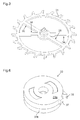
figure 1 est une vue en perspective d'une première forme d'exécution du mécanisme d'échappement à haute amplitude. - La
figure 2 illustre la roue d'échappement inférieure du mécanisme d'échappement illustré à lafigure 1 . - La
figure 3 illustre la roue d'échappement supérieure du mécanisme d'échappement illustré à lafigure 1 - La
figure 4 illustre l'ancre du mécanisme d'échappement illustrée à lafigure 1 . - La
figure 5 est une vue partielle de l'ancre illustrée à lafigure 4 . - La
figure 6 illustre le mobile de balancier du mécanisme d'échappement illustré à lafigure 1 . - Les
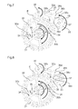
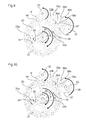
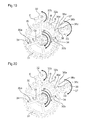
figures 7 à 25 illustrent les différentes phases de fonctionnement de la première forme d'exécution du mécanisme d'échappement illustré à lafigure 1 . - La
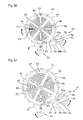
figure 26 illustre en perspective le mobile d'échappement d'une seconde forme d'exécution du mécanisme d'échappement selon l'invention. - La
figure 27 illustre en perspective la roue d'échappement inférieure du mobile d'échappement illustré à lafigure 26 . - La
figure 28 illustre en perspective la roue d'échappement supérieure vue de dessous du mobile d'échappement illustrée à lafigure 26 . - La
figure 29 illustre en perspective l'ancre de la seconde forme d'exécution du mécanisme d'échappement selon l'invention. - La
figure 30 illustre en perspective le mobile d'oscillateur de la seconde forme d'exécution du mécanisme d'échappement selon l'invention. - La
figure 31 illustre en perspective le mécanisme d'échappement selon la seconde forme d'exécution vu de dessous. - Les
figures 32 à 37 illustrent différentes phases de fonctionnement de la seconde forme d'exécution du mécanisme d'échappement.
- The
figure 1 is a perspective view of a first embodiment of the high amplitude escapement mechanism. - The
figure 2 illustrates the lower escape wheel of the exhaust mechanism shown infigure 1 . - The
figure 3 illustrates the exhaust upper wheel of the exhaust mechanism shown infigure 1 - The
figure 4 illustrates the anchor of the escape mechanism illustrated infigure 1 . - The
figure 5 is a partial view of the anchor shown in thefigure 4 . - The
figure 6 illustrates the pendulum wheel of the escapement mechanism illustrated infigure 1 . - The
Figures 7 to 25 illustrate the different operating phases of the first embodiment of the escape mechanism illustrated in FIG.figure 1 . - The
figure 26 illustrates in perspective the escape wheel of a second embodiment of the exhaust mechanism according to the invention. - The
figure 27 illustrates in perspective the lower escape wheel of the escape wheel illustrated in FIG.figure 26 . - The
figure 28 illustrates in perspective the upper escape wheel seen from below the escape mobile illustrated in FIG.figure 26 . - The
figure 29 illustrates in perspective the anchor of the second embodiment of the exhaust mechanism according to the invention. - The
figure 30 illustrates in perspective the oscillator mobile of the second embodiment of the exhaust mechanism according to the invention. - The
figure 31 illustrates in perspective the escape mechanism according to the second embodiment seen from below. - The
Figures 32 to 37 illustrate different phases of operation of the second embodiment of the escape mechanism.
Dans des formes d'exécution privilégiées de l'invention, le mécanisme d'échappement direct à force constante comporte :
- Un mobile d'échappement présentant un pignon d'échappement solidaire d'une roue d'échappement inférieure et une roue d'échappement supérieure. La roue d'échappement supérieure est montée coaxiale sur la roue d'échappement inférieure et est susceptible de se déplacer angulairement par rapport à cette roue d'échappement inférieure d'une amplitude angulaire prédéterminée. Ce mobile d'échappement comporte encore un ressort de force constante reliant la roue d'échappement inférieure à la roue d'échappement supérieure.
- Un mobile d'ancre comportant une palette d'entrée coopérant avec l'une des roues d'échappement et une palette de sortie coopérant avec l'autre des roues d'échappement. Ce mobile d'ancre comporte encore une fourchette.
- Un mobile d'oscillateur comportant une cheville coopérant avec la fourchette de l'ancre et un plan d'impulsion coopérant avec une des roues d'échappement du mobile d'échappement.
- An escape wheel having an exhaust pinion secured to a lower escape wheel and a wheel top exhaust. The upper escape wheel is mounted coaxially on the lower escape wheel and is capable of angularly moving relative to this lower exhaust wheel of a predetermined angular amplitude. This escapement mobile further comprises a constant force spring connecting the lower exhaust wheel to the upper exhaust wheel.
- An anchor wheel having an entry pallet cooperating with one of the escape wheels and an output pallet cooperating with the other of the escape wheels. This anchor mobile still has a fork.
- An oscillator wheel comprising a peg cooperating with the fork of the anchor and a pulse plane co-operating with one of the exhaust wheels of the escape wheel.
L'invention concerne également une pièce d'horlogerie mécanique et/ou un mouvement d'horlogerie mécanique comportant un moteur formé par exemple par un barillet, un rouage de finissage reliant ce moteur au pignon d'échappement du mobile d'échappement et un oscillateur, formé par exemple par un balancier-spiral, portant le mobile d'oscillateur.The invention also relates to a mechanical timepiece and / or mechanical clockwork comprising a motor formed for example by a cylinder, a work train connecting the engine to the exhaust pinion of the mobile and an oscillator , formed for example by a balance spring, carrying the oscillator mobile.
Dans ce qui suit la première forme d'exécution de l'échappement à haute amplitude, supérieure à 360°, sera décrite. Cette première forme d'exécution concerne un échappement direct avec un dispositif de force constante comprenant un mobile d'échappement comportant deux roues d'échappement liées de manière pivotante ensemble par un ressort spiral.In what follows, the first embodiment of the high amplitude escapement, greater than 360 °, will be described. This first embodiment relates to a direct exhaust with a constant force device comprising an exhaust mobile having two exhaust wheels pivotally connected together by a spiral spring.
Les
Ce mécanisme d'échappement à haute amplitude comporte un mobile d'échappement comprenant une roue d'échappement inférieure 30 et une roue d'échappement supérieure 31, une ancre 32 et un mobile d'oscillateur 33 fixé sur l'axe d'un oscillateur, typiquement un balancier-spiral.This high-amplitude escapement mechanism comprises an escape wheel comprising a
La roue d'échappement inférieure 30 est pivotée sur une platine d'un mouvement et comporte une première goupille 30a et une seconde goupille 30b.The
La roue d'échappement supérieure 31 est pivotée coaxialement sur la roue d'échappement inférieure 30 et comporte des rayons définissant des plans d'arrêt 34 et 35.The
L'ancre 32 comporte un axe, une ancre inférieure 32a comportant une palette d'entrée E et une palette de sortie S situées à des niveaux différents. La palette d'entrée E comporte sur son flanc extérieur un premier plan de repos 11 relié à une face terminale 10 par une formation de repos qui est de préférence formée d'un second plan de repos 12 et d'un troisième plan de repos 13 s'intersectant sur une ligne de repos 14.The
La palette de sortie S comporte sur son flanc interne un premier plan de repos 16 relié à une formation de repos qui est encore de préférence formée d'un second plan de repos 17 et d'un troisième plan de repos 18 s'intersectant sur une ligne de repos 19.The output pallet S has on its inner side a
La palette d'entrée E se trouve au même niveau que la roue d'échappement inférieure 30 et coopère avec celle-ci tandis que la palette de sortie S se trouve au niveau de la roue d'échappement supérieure 31 et coopère avec celle-ci.The entry pallet E is at the same level as the
L'ancre 32 comporte encore une ancre supérieure 32b dont l'extrémité comporte une fourchette à quatre dents 36a, 36b, 36c, 36d.The
Le mobile d'oscillateur 33 est composé de deux plateaux, un plateau de libération 33a, qui se trouve au même niveau que l'ancre supérieure 32b et qui comporte une cheville 37, et un plateau d'impulsion 33b, qui se trouve au même niveau que la roue d'échappement supérieure 31, qui comporte un plan d'impulsion 38 coopérant avec les dents de la roue d'échappement supérieure 31.The
Un ressort spiral de force constante (non illustré pour ne pas surcharger le dessin) dont une extrémité est fixée sur l'une des goupilles 30a ou 30b de la roue d'échappement inférieure 30 et l'autre extrémité est fixée à l'axe de la roue d'échappement supérieure 31 relie les deux roues d'échappement 30 et 31.A spiral spring of constant force (not illustrated not to overload the drawing) whose end is fixed on one of the
Le fonctionnement de cette première forme d'exécution du mécanisme d'échappement à haute amplitude sera décrit en référence aux
Dans sa première position d'équilibre (
L'ancre 32 est en appui sur une première butée fixe 20. L'orientation du premier plan de repos 11 de la palette d'entrée E fait que l'ancre 32 a tendance à tourner dans le sens anti horaire.The
Cette première phase d'équilibre dure jusqu'à ce que la cheville 37 vienne en contact avec la dent 36d de l'ancre supérieure 32b. A ce moment-là le mobile de balancier 33 entraine l'ancre 32 dans le sens horaire faisant reculer légèrement les roues d'échappement supérieure 31 et inférieure 30 via les goupilles 30a, 30b et les plans d'arrêt 34, 35 (
Cette première phase de libération dure jusqu'à ce que la dent ds de la roue d'échappement supérieure 31 quitte le premier plan de repos 11 de la palette d'entrée E et passe sur son second plan de repos 12. Le couple du rouage du mouvement et du ressort de force constante entraine l'ancre 32 dans le sens horaire grâce à l'orientation du second plan de repos 12 de la palette d'entrée E. Le contact entre la cheville 37 et l'ancre supérieure 32b est rompu. (
La roue d'échappement supérieure 31 vient en contact avec la ligne de repos 14 séparant le second plan de repos 12 et le troisième plan de repos 13 de la palette d'entre E. A ce moment-là les roues d'échappement supérieure 31 et inférieure 30 sont bloquées par la palette d'entrée E respectivement par les goupilles 30a, 30b de la roue d'échappement inférieure 30 et les plans d'arrêt 34, 35 de la roue d'échappement supérieure 31. De par la forme de la formation de repos concave formée par le second plan de repos 12 et le troisième plan de repos 13 de la palette d'entrée E l'ancre est replacée dans cette seconde position d'équilibre par les roues d'échappement. Le balancier est libre. Le mécanisme d'échappement est dans sa seconde position d'équilibre (
Lorsque la cheville 37 vient en contact avec la dent 36c de l'ancre supérieure 32b le balancier entraine l'ancre 32 dans le sens horaire faisant reculer légèrement les roues d'échappement supérieure 31 et inférieure 30 via la palette d'entrée E et les goupilles 30a, 30b de la roue d'échappement inférieure 30. C'est la seconde phase de libération (
La dent es de la roue d'échappement supérieure 31 quitte le troisième plan de repos 13 de la palette d'entrée E. A ce moment les roues d'échappement supérieure 31 et inférieure 30 sont libres de tourner dans le sens horaire. L'ancre 32 continue à tourner dans le sens horaire, la cheville 37 échappe à la dent 36c de l'ancre et le balancier est à nouveau libre. La roue d'échappement supérieure 31 n'est plus bloquée et tourne dans le sens horaire grâce au ressort de force constante. La roue d'échappement inférieure 30 vient au contact du troisième plan de repos 18 de la palette de sortie S (
Au moment où les goupilles 30a, 30b de la roue d'échappement inférieure 30 viennent au contact des plans d'arrêt 34, 35 de la roue d'échappement supérieure 31 la roue d'échappement inférieure 30 et le mobile d'ancre 32 sont bloqués ainsi que la roue d'échappement supérieure 31.At the moment when the
Juste avant que la roue d'échappement supérieure 31 ne soit bloquée sa dent di se sépare du plan d'impulsion 38. Le balancier est à nouveau libre. Le mécanisme d'échappement est dans sa troisième position d'équilibre (
Lorsque la cheville 37 entre en contact avec la dent 36b de l'ancre supérieure 32b le balancier entraine l'ancre 32 dans le sens horaire. La roue d'échappement inférieure 30 di va alors légèrement reculer ce qui entraine la roue d'échappement supérieure 31 via les goupilles 30a, 30b et les plans d'arrêt 34, 35 de la roue d'échappement supérieure 31 (
A ce moment l'ancre 32 est bloquée en contact avec cette seconde butée fixe 21 et les roues d'échappement supérieure 31 et inférieure 30 sont également bloquées, la roue d'échappement inférieure 30 contre le premier plan de repos 16 de la palette de sortie S avec sa dent di et la roue d'échappement supérieure 31 par l'intermédiaire des goupilles 30a, 30b de la roue d'échappement inférieure 30. Durant cette quatrième phase ou position d'équilibre le balancier est toujours libre et va terminer son alternance et repartir dans le sens horaire pour sa seconde alternance (
La quatrième position d'équilibre est maintenue jusqu'à ce que la cheville 37 vienne en contact avec la dent 36a de l'ancre supérieure 32b. A ce moment le mobile de balancier 33 entraine l'ancre 32 dans le sens anti horaire faisant reculer légèrement la roue d'échappement inférieure 30 et donc la roue d'échappement supérieure 31 via les goupilles 30a, 30b de la roue d'échappement inférieure en appui avec le plan d'arrêt 35 de la roue d'échappement supérieure 31 (
Cette quatrième phase de libération dure jusqu'à ce que la dent di de la roue d'échappement inférieure 30 quitte le premier plan de repos 16 de la palette de sortie S et passe sur le second plan de repos 17 de cette palette de sortie S (
Lorsque la cheville 37 du mobile de balancier 33 vient en contact avec la dent 36b de l'ancre supérieure 32b le balancier entraine l'ancre 32 dans le sens anti horaire en faisant reculer légèrement la roue d'échappement inférieure 30 et donc la roue d'échappement supérieure via les goupilles 30a, 30b et le plan d'arrêt 34 (
Cette cinquième phase de libération dure jusqu'à ce que la dent di de la roue d'échappement inférieure 30 quitte le troisième plan de repos 18 de la palette de sortie S. A ce moment les deux roues d'échappement supérieure 31 et inférieure 30 sont libres de tourner dans le sens horaire. L'ancre 32 continue à tourner dans le sens anti horaire et le balancier est à nouveau libre. La roue d'échappement supérieure 31 vient par l'intermédiaire d'une de ses dents ds en contact avec le troisième plan de repos 13 de la palette d'entrée E. Cette dent ds va se placer sur la ligne de repos 14 de la palette d'entrée E sous l'effet du couple du rouage et de l'orientation des second 12 et troisième 13 plans de repos de la palette d'entrée E positionnant l'ancre 32 de manière à ce que le balancier soit à nouveau libre.This fifth release phase lasts until the tooth di of the
La roue d'échappement inférieure 30 n'est plus bloquée et tourne dans le sens horaire grâce au couple du rouage. On perd le contact entre les goupilles 30a, 30b de la roue d'échappement inférieure 30 et le plan d'arrêt 34 de la roue d'échappement supérieure 31. Ainsi on recharge le ressort de force constante reliant la roue d'échappement inférieure 30 à la roue d'échappement supérieure 31 (
Cette sixième phase de libération dure jusqu'à ce que la dent ds de la roue d'échappement supérieure 31 quitte le second plan de repos 12 de la palette d'entrée E et passe sur le premier plan de repos 11 de cette palette d'entrée E. Le couple du rouage et du ressort de force constante entraine l'ancre 32 dans le sens anti horaire, grâce à l'orientation du premier plan de repos 11 de la palette d'entrée E. Le contact entre la cheville 37 du mobile de balancier 33 est rompu d'avec l'ancre supérieure. Cette sixième phase de libération dure jusqu'à ce que l'ancre 32 vienne en contact avec la première butée fixe 20. On se retrouve dans la première position d'équilibre (
La particularité de ce mécanisme d'échappement est de permettre des phases d'équilibre où le balancier peut poursuivre son alternance en faisant osciller l'ancre sans libérer les roues d'échappements. Ceci est obtenu grâce à la juxtaposition de plusieurs formations de repos et notamment grâce à la présence d'une formation de repos supplémentaire sur les palettes, ce qui permet au balancier d'effectuer plusieurs tours pour chaque alternance alors que l'impulsion n'est donnée qu'une fois par alternance lorsque l'ancre est déplacée suffisamment pour libérer le mobile d'échappement. De préférence, les palettes d'entrée E et de sortie S ont des second et troisième plans de repos qui forment une formation de repos concave, par exemple en forme de V (ou de U), mais d'autres formes sont également possibles, même une forme plate.The special feature of this escapement mechanism is to allow balance phases where the balance can continue its alternation by oscillating the anchor without releasing the escape wheels. This is achieved thanks to the juxtaposition of several rest formations and notably thanks to the presence an additional rest formation on the pallets, which allows the balance to perform several turns for each alternation while the pulse is given only once per alternation when the anchor is moved sufficiently to release the mobile exhaust. Preferably, the entry and exit pallets S have second and third rest planes which form a concave rest formation, for example V-shaped (or U-shaped), but other shapes are also possible, even a flat shape.
Ce mécanisme se distingue donc en ce que la palette d'entrée E et la palette de sortie S de l'ancre comporte un premier plan de repos et au moins une formation de repos supplémentaire, jouxtant le premier plan de repos. De préférence, cette formation est concave et formée d'un deuxième plan de repos et d'un troisième plan de repos formant un V entre eux et définissant par leur intersection une ligne de repos. Ainsi lorsque le mobile d'échappement repose par une de ses dents sur la formation de repos concave sous l'effet du couple du rouage la dent du mobile d'échappement tend à se placer sur la ligne de repos. Si l'ancre est légèrement déplacée lors d'un choc par exemple elle ne quitte pas sa position d'équilibre mais se replace automatiquement dans sa position définie par la dent du mobile d'échappement entrant en contact avec la ligne de repos de la formation de repos concave soit l'intersection entre le second plan de repos et le troisième plan de repos.This mechanism is therefore distinguished in that the entry pallet E and the output pallet S of the anchor comprises a first rest plane and at least one additional rest formation, adjacent to the first rest plane. Preferably, this formation is concave and formed of a second plane of rest and a third plane of rest forming a V between them and defining by their intersection a line of rest. Thus, when the escape wheel rests by one of its teeth on the concave rest formation under the effect of the torque of the gear train, the tooth of the escapement wheel tends to be placed on the line of rest. If the anchor is slightly displaced during an impact, for example, it does not leave its equilibrium position but automatically returns to its position defined by the tooth of the mobile escapement coming into contact with the line of rest of the formation concave rest is the intersection between the second rest plane and the third rest plane.
De manière privilégiée, un tel mécanisme d'échappement comprend également une ancre dont l'extrémité coopérant avec la cheville du mobile de balancier comporte au moins quatre dents et non pas une fourchette simple à deux dents.In a preferred manner, such an escapement mechanism also comprises an anchor whose end cooperating with the peg of the balance wheel comprises at least four teeth and not a simple fork with two teeth.
Dans cette forme d'exécution, chaque palette d'entrée E et de sortie S comporte une formation de repos concave, généralement en forme de V formée par un second plan de repos et un troisième plan de repos dont l'intersection forme une ligne de repos. Chaque palette, d'entrée E et de sortie S, comporte également un premier plan de repos situé sur la tranche externe respectivement interne de la palette et jouxtant la formation de repos concave, généralement en forme de V.In this embodiment, each entry and exit pallet E has a concave, generally V-shaped rest formation formed by a second rest plane and a third rest plane whose intersection forms a line of rest. Each pallet, input E and output S, also has a first rest plane located on the outer edge respectively internal to the pallet and adjoining the concave rest formation, usually V-shaped.
Dans cette forme d'exécution les quatre dents de l'ancre supérieure coopérant avec la cheville du mobile de balancier peuvent toutes être identiques puisqu'aucune d'elles ne sert à donner l'impulsion au balancier.In this embodiment, the four teeth of the upper anchor cooperating with the peg of the balance wheel can all be identical since none of them serves to give the impulse to the pendulum.
Le balancier effectue plusieurs tours, généralement deux à trois tours, par alternance. Une impulsion est délivrée au plan d'impulsion par le mobile d'échappement directement pour chaque alternance du balancier. Par contre, à chaque tour de l'alternance du balancier, la cheville coopère avec les dents de la fourchette de l'ancre pour faire osciller celle-ci et laisser passer ladite cheville mais sans provoquer la libération du mobile d'échappement qui, sous l'effet du rouage, replace l'ancre dans une position d'équilibre lorsque l'impulsion n'est pas délivrée au balancier.The pendulum performs several turns, usually two to three turns, alternately. A pulse is delivered to the pulse plane by the escapement mobile directly for each alternation of the balance. On the other hand, at each turn of the alternation of the balance, the peg cooperates with the teeth of the fork of the anchor to oscillate it and let pass said pin but without causing the release of the mobile escape which, under the effect of the gear, puts the anchor in a position of equilibrium when the pulse is not delivered to the balance.
De manière avantageuse, la forme concave, généralement en forme de U ou de préférence de V de la formation de repos formée par les premier 11 ;16 et les second 12 ;17 plans de repos des palettes d'entrée E et de sortie S et l'orientation de ces plans par rapport à l'axe de rotation de l'ancre, font que sous l'effet du couple fourni par le rouage le mobile d'échappement remet en position d'équilibre l'ancre lorsque celle-ci est légèrement décalée dans un sens ou dans l'autre, par exemple suite à un choc On voit que le passage de la position d'équilibre sur le premier plan de repos 11, 16 de la palette d'entrée E respectivement de sortie S à la position d'équilibre sur la formation de repos 14, 19 de ces palettes d'entrée E et de sortie S est réalisé par une oscillation de l'ancre 32 provoquée par le mobile de balancier, agissant sur la fourchette de l'ancre et donc par l'énergie du balancier. Cette oscillation de l'ancre permet au balancier d'effectuer plusieurs tours pour chaque alternance de ces oscillations tout en ne provoquant la libération du mobile d'échappement qu'une seule fois par alternance du balancier.Advantageously, the concave, generally U-shaped or preferably V-shaped form of the rest formation formed by the first 11; 16 and second 12; 17 rest planes of the entry and exit pallets E and S the orientation of these planes with respect to the axis of rotation of the anchor, cause that under the effect of the torque provided by the wheelhouse, the escapement wheel returns the anchor in equilibrium position when the latter is slightly shifted in one direction or the other, for example following a shock It is seen that the passage of the equilibrium position on the first plane of
Cette particularité des plans de repos des palettes d'entrée et de sortie de l'ancre fait que le mécanisme d'échappement peut fonctionner aussi bien avec des alternances du balancier inférieures à 360° que supérieures à 360°, ces dernières permettant une plus grande précision chronométrique et l'obtention d'une plus grande puissance emmagasinée dans l'oscillateur particulièrement le balancier.This particularity of the resting planes of the pallets of entry and exit of the anchor makes that the escape mechanism can function as well with oscillations of the balance lower than 360 ° than higher than 360 °, the latter allowing a greater chronometric accuracy and obtaining a greater power stored in the oscillator, particularly the pendulum.
Dans des variantes du mécanisme d'échappement décrit, on peut augmenter le nombre de tours du balancier pour chacune de ses alternances en multipliant le nombre de positions de repos sur les palettes d'entrée et de sortie ainsi que le nombre de dents de la fourchette de l'ancre. On peut donc envisager un mécanisme d'échappement où le balancier effectuerait des alternances de plus de 720° d'amplitude avec un fonctionnement similaire aux formes d'exécution illustrées.In variants of the escapement mechanism described, it is possible to increase the number of turns of the balance for each of its alternations by multiplying the number of rest positions on the entry and exit pallets as well as the number of teeth of the fork. from the anchor. It is therefore possible to envisage an escapement mechanism in which the balance would effect alternations of more than 720 ° amplitude with operation similar to the illustrated embodiments.
De plus, il est possible de jouer sur le dimensionnement des palettes d'entrée et de sortie et notamment sur les longueurs des premiers plans de repos 11, 12 et des seconds plans de repos 16, 17 de ces palettes pour modifier l'isochronisme de l'échappement et ainsi pouvoir mieux compenser l'isochronisme du spiral du balancier-spiral afin de réaliser un assortiment le plus précis possible.In addition, it is possible to play on the dimensioning of the entry and exit pallets and in particular on the lengths of the first rest planes 11, 12 and the second rest planes 16, 17 of these pallets to modify the isochronism of the escapement and thus be better able to compensate the isochronism of the spiral balance-spiral to achieve a more accurate assortment possible.
La seconde forme d'exécution du mécanisme d'échappement direct à force constante est illustrée aux
- Le mobile d'échappement qui comporte une roue d'échappement inférieure 40 solidaire d'un
axe 41 portant également un pignon d'échappement 42 destiné à être relié au moteur, généralement un barillet, d'un mouvement d'horlogerie mécanique par l'intermédiaire d'un rouage de finissage de ce mouvement.
La serge de cette roue d'échappement inférieure comporte des entailles 43 au nombre de quatre distribuées uniformément autour de sa périphérie. Ce mobile d'échappement comporte encore une roue d'échappement supérieure 44 comportant des tétons 45 émergeant de sa surface inférieure. Cette roue d'échappement supérieure 44 est montée pivotante coaxialement à la roue d'échappement inférieure 40 sur l'axe 41 de celle-ci. Les tétons 45, une fois les roues d'échappement 40, 45 montées l'une sur l'autre, s'étendent dans les entailles 43 de la roue d'échappement inférieure 40.
De cette façon, l'amplitude angulaire du déplacement de ces roues d'échappement 40, 44 l'une par rapport à l'autre est limitée à une valeur préétablie. Ce mobile d'échappement comporte encore un ressort spiral deforce constante 46 dont l'extrémité intérieure est fixée à l'axe 41 et dont l'extrémité extérieure est fixée à la roue d'échappement supérieure 44.
Ce ressort de forceconstante 46 est précontraint et tend à faire tourner la roue d'échappement supérieure 44 dans le sens horaire par rapport à la roue d'échappement inférieure 40. Cette rotation relative entre les deux roues d'échappement 40, 44 est limitée par l'entrée en contact des tétons 45 de la roue d'échappement supérieure 44 avec l'une ou l'autre extrémité des entailles 43 de la serge de la roue d'échappement inférieure 40. Le couple de ce ressort de forceconstante 46 est inférieur au couple transmis par le rouage de finissage du mouvement à la roue d'échappement inférieure 40. - Un
mobile d'ancre 47 comportant une palette d'entrée E coopérant avec la denture de la roue d'échappement supérieure 44 et une palette de sortie S coopérant avec la denture de la roue d'échappement inférieure 40.
Cette ancre 47 comporteencore une fourchette 48 comportant deux dents 49a, 49b. Un dard 50 est monté sur, ou venu d'une pièce de fabrication avec la fourchette de l'ancre 47. - Un mobile d'oscillateur ou de balancier 51 porté par l'axe d'un oscillateur, généralement d'un balancier-spiral, comporte
un plateau d'impulsion 51a présentantun plan d'impulsion 52, un plateau de libération 51 bprésentant une cheville 53 et un plateau de dard 51 c comportant un rebord cylindrique 54 munis d'une ouverture 54a. Le plan d'impulsion 52 dumobile d'oscillateur 51 coopère avec la denture de la roue d'échappement supérieure 44 et la cheville 53 coopère avec les dents 49a, 49b de la fourchette 48 de l'ancre 47.
- The escapement wheel which comprises a
lower exhaust wheel 40 integral with anaxis 41 also carrying anexhaust pinion 42 intended to be connected to the engine, generally a cylinder, a mechanical clockwork movement by the intermediate of a gear train of this movement.
The serge of this lower escape wheel comprisesnotches 43 four in number distributed uniformly around its periphery. This escapement mobile also comprises anupper escape wheel 44 havingpins 45 emerging from its lower surface. Thisupper exhaust wheel 44 is pivotally mounted coaxially with thelower exhaust wheel 40 on theaxis 41 thereof. Thenipples 45, once theescape wheels notches 43 of thelower escape wheel 40.
In this way, the angular amplitude of the displacement of theseescape wheels constant force 46 whose inner end is fixed to theaxis 41 and whose outer end is fixed to theupper escapement wheel 44.
Thisconstant force spring 46 is prestressed and tends to rotate theupper escapement wheel 44 clockwise relative to thelower escapement wheel 40. This relative rotation between the twoescape wheels pins 45 of theupper escapement wheel 44 with one or the other end of thenotches 43 of the serge of thelower escapement wheel 40. The torque of this spring ofconstant force 46 is less than the torque transmitted by the finishing gear of the movement to thelower escape wheel 40. - An
anchor wheel 47 comprising an entry pallet E cooperating with the toothing of theupper escape wheel 44 and an output pallet S cooperating with the toothing of thelower escape wheel 40.
Thisanchor 47 further comprises afork 48 comprising twoteeth dart 50 is mounted on, or come from a work piece with the fork of theanchor 47. - An oscillator or
balance wheel 51 carried by the axis of an oscillator, generally a balance-spring, comprises apulse plate 51a having apulse plane 52, arelease plate 51b having aankle 53 and astinger plate 51c having acylindrical rim 54 provided with anopening 54a. Theimpulse plane 52 of theoscillator wheel 51 cooperates with the toothing of theupper escapement wheel 44 and thepin 53 cooperates with theteeth fork 48 of theanchor 47.
Le fonctionnement de cette seconde forme d'exécution du mécanisme d'échappement sera décrit dans ce qui suit en référence aux
Lorsque le mécanisme d'échappement est dans sa première position d'équilibre (
Dans la première phase de libération (
Une fois que la roue d'échappement supérieure 44 est complètement libérée, la roue d'échappement inférieure 40 se trouve bloquée sur la palette de sortie S de l'ancre 47. La forme de cette palette de sortie est telle qu'un couple dans le sens anti horaire est appliqué à l'ancre 47 qui vient buter contre une seconde butée fixe 56. Le couple du ressort de force constante 46 reliant la roue d'échappement inférieure 40 à la roue d'échappement supérieure 44 entraîne cette roue d'échappement supérieure 44. Une dent de cette roue d'échappement supérieure 44 entre en contact avec le plan d'impulsion 52 du mobile de balancier 51 et transmet ainsi de l'énergie au balancier. C'est la phase d'impulsion (
Cette phase d'impulsion dure jusqu'à ce que la roue d'échappement inférieure vienne en butée contre la roue d'échappement supérieure 44 par ses tétons 45 venant en contact des extrémités des entailles 43 de la roue d'échappement inférieure 40 (
Dans cette seconde phase d'équilibre, le balancier est à nouveau libre. La roue d'échappement inférieure 40 est bloquée par la palette de sortie S de l'ancre 47 et celle-ci est en butée sur la seconde butée fixe 56.In this second phase of equilibrium, the balance is free again. The
La roue d'échappement supérieure 44 est en butée contre la roue d'échappement inférieure 40 via les tétons 45 et les extrémités des entailles 43. Le couple du ressort de force constante 46 maintient la roue d'échappement supérieure 44 en butée sur la roue d'échappement inférieure 40.The
Le balancier termine sa course et inverse son sens de rotation. La cheville 53 entre en contact avec la dent 49b de la fourchette 48 de l'ancre 47 et entraine l'ancre dans le sens horaire. C'est la seconde phase de libération (
Cette seconde phase de libération dure jusqu'à ce que la dent de la roue d'échappement inférieure 40 soit complètement dégagée de la palette de sortie S de l'ancre 47. On notera qu'avant que la palette de sortie S ne soit dégagée, la palette d'entrée E de l'ancre vient se placer sur le chemin d'une dent de la roue d'échappement supérieure 44.This second release phase lasts until the tooth of the
Une fois la roue d'échappement inférieure 40 complètement libérée (
Le couple appliqué par le rouage de finissage du mouvement à la roue d'échappement inférieure 40 étant supérieur au couple du ressort de force constante 46 permet ainsi d'entraîner en rotation la roue d'échappement supérieure 44 provoquant la recharge du ressort de force constante 46. Cette phase de recharge de la force constante dure jusqu'à ce que la roue d'échappement inférieure 40 vienne buter contre la roue d'échappement supérieure 44 via les tétons 45 et les faces terminales des entailles 43.The torque applied by the finishing gear of the movement to the
Le mécanisme d'échappement est revenu en position d'équilibre initiale et un nouveau cycle peut recommencer.The escape mechanism has returned to the initial equilibrium position and a new cycle can begin again.
Ce mécanisme d'échappement dispose d'un dispositif anti choc.This exhaust mechanism has an anti-shock device.
Pour de faibles chocs, c'est l'orientation des palettes d'entrée E et de sortie S qui permet de maintenir les positions du mécanisme d'échappement.For low shocks, it is the orientation of the entry and exit pallets E S that maintains the positions of the exhaust mechanism.
Pour des chocs plus importants, avant qu'une dent des roues d'échappement 40, 44 ne se libère des palettes de l'ancre, le dard 50 vient en contact avec le rebord cylindrique 54 du plateau de dard 51 c empêchant la libération des roues d'échappement 40, 44.For greater impact, before a tooth of the
Le dard 50 se place tantôt à l'intérieur du rebord cylindrique 54 (empêchant la rotation de l'ancre dans le sens horaire) tantôt à l'extérieur du rebord cylindrique 54 (empêchant la rotation de l'ancre dans le sens anti horaire). L'ouverture 54a dans le rebord cylindrique 54 du plateau de dard 51 c permet le déplacement de l'ancre pendant les phases de fonctionnement du mécanisme d'échappement.The
Les avantages de ces deux formes d'exécution du mécanisme d'échappement sont :
- Un haut rendement car on a supprimé les phases de perte telle que la chute.
- Un meilleur fonctionnement à haute fréquence car la roue d'échappement qui donne l'impulsion est isolée et présente donc une faible inertie.
- La force constante permet une meilleure chronométrie.
- Les mécanismes sont robustes, faciles à usiner et à assembler.
- High efficiency because we have eliminated the phases of loss such as the fall.
- Better operation at high frequency because the impeller that gives the impulse is isolated and therefore has low inertia.
- The constant force allows a better chronometry.
- The mechanisms are robust, easy to machine and assemble.
La première forme d'exécution permet en plus un fonctionnement de l'oscillateur à une amplitude supérieur à 360° au détriment d'une partie de son rendementThe first embodiment also allows the oscillator to operate at an amplitude greater than 360 ° to the detriment of part of its performance.
Claims (13)
Priority Applications (1)
| Application Number | Priority Date | Filing Date | Title |
|---|---|---|---|
| EP15177689.5A EP3121661B1 (en) | 2015-07-21 | 2015-07-21 | Constant-force direct escapement mechanism |
Applications Claiming Priority (1)
| Application Number | Priority Date | Filing Date | Title |
|---|---|---|---|
| EP15177689.5A EP3121661B1 (en) | 2015-07-21 | 2015-07-21 | Constant-force direct escapement mechanism |
Publications (2)
| Publication Number | Publication Date |
|---|---|
| EP3121661A1 true EP3121661A1 (en) | 2017-01-25 |
| EP3121661B1 EP3121661B1 (en) | 2018-05-23 |
Family
ID=53682587
Family Applications (1)
| Application Number | Title | Priority Date | Filing Date |
|---|---|---|---|
| EP15177689.5A Active EP3121661B1 (en) | 2015-07-21 | 2015-07-21 | Constant-force direct escapement mechanism |
Country Status (1)
| Country | Link |
|---|---|
| EP (1) | EP3121661B1 (en) |
Cited By (5)
| Publication number | Priority date | Publication date | Assignee | Title |
|---|---|---|---|---|
| CN106707718A (en) * | 2017-03-01 | 2017-05-24 | 谭泽华 | Escapement for impact of split shaft of clock |
| PL423844A1 (en) * | 2017-12-11 | 2019-06-17 | Grzegorz Szychliński | Pendulum clock escapement assemble |
| WO2020015889A1 (en) * | 2018-07-20 | 2020-01-23 | Creaditive Ag | Escapement system and measuring device comprising said escapement system |
| US20210141340A1 (en) * | 2018-07-02 | 2021-05-13 | Complitime Sa | Timepiece escapement mechanism |
| US11397408B2 (en) | 2018-05-25 | 2022-07-26 | Société Anonyme de la Manufacture d'Horlogerie Audemars Piguet & Cie | Automatically starting and secured detent escapement for a timepiece |
Citations (5)
| Publication number | Priority date | Publication date | Assignee | Title |
|---|---|---|---|---|
| DE178113C (en) * | ||||
| CH223109A (en) * | 1941-10-01 | 1942-08-31 | Theurillat Xavier | So-called constant force escapement device for clock movements, counters, etc. |
| FR1009853A (en) * | 1948-07-02 | 1952-06-04 | Sophisticated exhaust mechanism | |
| US2970427A (en) | 1957-03-28 | 1961-02-07 | Gen Time Corp | Constant torque escapement |
| CH353679A (en) | 1959-03-24 | 1961-04-15 | Theurillat Xavier | Constant force exhaust |
-
2015
- 2015-07-21 EP EP15177689.5A patent/EP3121661B1/en active Active
Patent Citations (5)
| Publication number | Priority date | Publication date | Assignee | Title |
|---|---|---|---|---|
| DE178113C (en) * | ||||
| CH223109A (en) * | 1941-10-01 | 1942-08-31 | Theurillat Xavier | So-called constant force escapement device for clock movements, counters, etc. |
| FR1009853A (en) * | 1948-07-02 | 1952-06-04 | Sophisticated exhaust mechanism | |
| US2970427A (en) | 1957-03-28 | 1961-02-07 | Gen Time Corp | Constant torque escapement |
| CH353679A (en) | 1959-03-24 | 1961-04-15 | Theurillat Xavier | Constant force exhaust |
Cited By (9)
| Publication number | Priority date | Publication date | Assignee | Title |
|---|---|---|---|---|
| CN106707718A (en) * | 2017-03-01 | 2017-05-24 | 谭泽华 | Escapement for impact of split shaft of clock |
| CN106707718B (en) * | 2017-03-01 | 2019-01-29 | 谭泽华 | Clock and watch split axle impacts release catch |
| PL423844A1 (en) * | 2017-12-11 | 2019-06-17 | Grzegorz Szychliński | Pendulum clock escapement assemble |
| US11397408B2 (en) | 2018-05-25 | 2022-07-26 | Société Anonyme de la Manufacture d'Horlogerie Audemars Piguet & Cie | Automatically starting and secured detent escapement for a timepiece |
| US20210141340A1 (en) * | 2018-07-02 | 2021-05-13 | Complitime Sa | Timepiece escapement mechanism |
| WO2020015889A1 (en) * | 2018-07-20 | 2020-01-23 | Creaditive Ag | Escapement system and measuring device comprising said escapement system |
| US20210286320A1 (en) * | 2018-07-20 | 2021-09-16 | Creaditive Ag | Escapement system and measuring device comprising said escapement system |
| JP2021531479A (en) * | 2018-07-20 | 2021-11-18 | クレアディティヴ・アーゲー | Escapement system and measuring device equipped with it |
| JP7441835B2 (en) | 2018-07-20 | 2024-03-01 | クレアディティヴ・アーゲー | Escapement system and measuring device equipped with the same |
Also Published As
| Publication number | Publication date |
|---|---|
| EP3121661B1 (en) | 2018-05-23 |
Similar Documents
| Publication | Publication Date | Title |
|---|---|---|
| EP3121661B1 (en) | Constant-force direct escapement mechanism | |
| EP2645189B1 (en) | Flexible escapement mechanism | |
| EP2487546B1 (en) | High-performance bi-axial escapement, or HPBE | |
| WO2009118310A1 (en) | Escapement mechanism | |
| EP3070537A1 (en) | Time base comprising an escapement with direct pulse and constant force | |
| EP2407830A1 (en) | Timepiece | |
| EP2607968B1 (en) | Escapement mechanism | |
| CH714200B1 (en) | An escapement device for a mechanical watch movement comprising an escapement with two escapement moving parts. | |
| EP3570117A1 (en) | Escapement mechanism for timepiece | |
| EP3781994B1 (en) | Rest anchor escapment mechanism and timepiece comprising such an escapment mechanism | |
| CH701921A2 (en) | Lever escapement mechanism for watch, has gears connected to escapement wheels that are arranged with pallets in alternate way, body swiveled on support around axis, and anchor provided with pallet | |
| CH713530B1 (en) | Escapement, timepiece movement and timepiece. | |
| EP3781993B1 (en) | Free direct escapement mechanism for watches. | |
| CH712288A1 (en) | Bi-functional sting, locking and securing device for timepiece, and watch exhaust. | |
| CH712807B1 (en) | Exhaust mechanism. | |
| EP3475765B1 (en) | Clock escapement | |
| EP1837718B1 (en) | Escapement device for a timepiece movement | |
| EP3599514B1 (en) | Exhaust mechanism having bistable and monostable springs | |
| CH704784B1 (en) | Exhaust anchor comprising two escape wheels. | |
| EP4250019A1 (en) | Timepiece oscillator for extra-flat movement | |
| WO2015004336A2 (en) | Escapement for a timepiece with a tourbillon without a cage | |
| EP4303664A1 (en) | Timepiece movement and timepiece comprising such a movement | |
| CH709755A2 (en) | clockwork mechanism with a tuning fork resonator. | |
| CH713800B1 (en) | Watchmaking mechanism comprising an anchor escapement mechanism and an oscillating regulator. | |
| EP3479175A1 (en) | Mechanical clock movement |
Legal Events
| Date | Code | Title | Description |
|---|---|---|---|
| PUAI | Public reference made under article 153(3) epc to a published international application that has entered the european phase |
Free format text: ORIGINAL CODE: 0009012 |
|
| AK | Designated contracting states |
Kind code of ref document: A1 Designated state(s): AL AT BE BG CH CY CZ DE DK EE ES FI FR GB GR HR HU IE IS IT LI LT LU LV MC MK MT NL NO PL PT RO RS SE SI SK SM TR |
|
| AX | Request for extension of the european patent |
Extension state: BA ME |
|
| 17P | Request for examination filed |
Effective date: 20170720 |
|
| RBV | Designated contracting states (corrected) |
Designated state(s): AL AT BE BG CH CY CZ DE DK EE ES FI FR GB GR HR HU IE IS IT LI LT LU LV MC MK MT NL NO PL PT RO RS SE SI SK SM TR |
|
| GRAP | Despatch of communication of intention to grant a patent |
Free format text: ORIGINAL CODE: EPIDOSNIGR1 |
|
| INTG | Intention to grant announced |
Effective date: 20180102 |
|
| GRAS | Grant fee paid |
Free format text: ORIGINAL CODE: EPIDOSNIGR3 |
|
| GRAA | (expected) grant |
Free format text: ORIGINAL CODE: 0009210 |
|
| AK | Designated contracting states |
Kind code of ref document: B1 Designated state(s): AL AT BE BG CH CY CZ DE DK EE ES FI FR GB GR HR HU IE IS IT LI LT LU LV MC MK MT NL NO PL PT RO RS SE SI SK SM TR |
|
| REG | Reference to a national code |
Ref country code: GB Ref legal event code: FG4D Free format text: NOT ENGLISH |
|
| REG | Reference to a national code |
Ref country code: CH Ref legal event code: EP Ref country code: CH Ref legal event code: NV Representative=s name: MICHELI AND CIE SA, CH |
|
| REG | Reference to a national code |
Ref country code: IE Ref legal event code: FG4D Free format text: LANGUAGE OF EP DOCUMENT: FRENCH |
|
| REG | Reference to a national code |
Ref country code: AT Ref legal event code: REF Ref document number: 1001999 Country of ref document: AT Kind code of ref document: T Effective date: 20180615 |
|
| REG | Reference to a national code |
Ref country code: DE Ref legal event code: R096 Ref document number: 602015011359 Country of ref document: DE |
|
| REG | Reference to a national code |
Ref country code: FR Ref legal event code: PLFP Year of fee payment: 4 |
|
| REG | Reference to a national code |
Ref country code: NL Ref legal event code: MP Effective date: 20180523 |
|
| REG | Reference to a national code |
Ref country code: LT Ref legal event code: MG4D |
|
| PG25 | Lapsed in a contracting state [announced via postgrant information from national office to epo] |
Ref country code: NO Free format text: LAPSE BECAUSE OF FAILURE TO SUBMIT A TRANSLATION OF THE DESCRIPTION OR TO PAY THE FEE WITHIN THE PRESCRIBED TIME-LIMIT Effective date: 20180823 Ref country code: FI Free format text: LAPSE BECAUSE OF FAILURE TO SUBMIT A TRANSLATION OF THE DESCRIPTION OR TO PAY THE FEE WITHIN THE PRESCRIBED TIME-LIMIT Effective date: 20180523 Ref country code: BG Free format text: LAPSE BECAUSE OF FAILURE TO SUBMIT A TRANSLATION OF THE DESCRIPTION OR TO PAY THE FEE WITHIN THE PRESCRIBED TIME-LIMIT Effective date: 20180823 Ref country code: SE Free format text: LAPSE BECAUSE OF FAILURE TO SUBMIT A TRANSLATION OF THE DESCRIPTION OR TO PAY THE FEE WITHIN THE PRESCRIBED TIME-LIMIT Effective date: 20180523 Ref country code: ES Free format text: LAPSE BECAUSE OF FAILURE TO SUBMIT A TRANSLATION OF THE DESCRIPTION OR TO PAY THE FEE WITHIN THE PRESCRIBED TIME-LIMIT Effective date: 20180523 Ref country code: LT Free format text: LAPSE BECAUSE OF FAILURE TO SUBMIT A TRANSLATION OF THE DESCRIPTION OR TO PAY THE FEE WITHIN THE PRESCRIBED TIME-LIMIT Effective date: 20180523 |
|
| PG25 | Lapsed in a contracting state [announced via postgrant information from national office to epo] |
Ref country code: HR Free format text: LAPSE BECAUSE OF FAILURE TO SUBMIT A TRANSLATION OF THE DESCRIPTION OR TO PAY THE FEE WITHIN THE PRESCRIBED TIME-LIMIT Effective date: 20180523 Ref country code: NL Free format text: LAPSE BECAUSE OF FAILURE TO SUBMIT A TRANSLATION OF THE DESCRIPTION OR TO PAY THE FEE WITHIN THE PRESCRIBED TIME-LIMIT Effective date: 20180523 Ref country code: LV Free format text: LAPSE BECAUSE OF FAILURE TO SUBMIT A TRANSLATION OF THE DESCRIPTION OR TO PAY THE FEE WITHIN THE PRESCRIBED TIME-LIMIT Effective date: 20180523 Ref country code: GR Free format text: LAPSE BECAUSE OF FAILURE TO SUBMIT A TRANSLATION OF THE DESCRIPTION OR TO PAY THE FEE WITHIN THE PRESCRIBED TIME-LIMIT Effective date: 20180824 Ref country code: RS Free format text: LAPSE BECAUSE OF FAILURE TO SUBMIT A TRANSLATION OF THE DESCRIPTION OR TO PAY THE FEE WITHIN THE PRESCRIBED TIME-LIMIT Effective date: 20180523 |
|
| REG | Reference to a national code |
Ref country code: AT Ref legal event code: MK05 Ref document number: 1001999 Country of ref document: AT Kind code of ref document: T Effective date: 20180523 |
|
| PG25 | Lapsed in a contracting state [announced via postgrant information from national office to epo] |
Ref country code: EE Free format text: LAPSE BECAUSE OF FAILURE TO SUBMIT A TRANSLATION OF THE DESCRIPTION OR TO PAY THE FEE WITHIN THE PRESCRIBED TIME-LIMIT Effective date: 20180523 Ref country code: PL Free format text: LAPSE BECAUSE OF FAILURE TO SUBMIT A TRANSLATION OF THE DESCRIPTION OR TO PAY THE FEE WITHIN THE PRESCRIBED TIME-LIMIT Effective date: 20180523 Ref country code: DK Free format text: LAPSE BECAUSE OF FAILURE TO SUBMIT A TRANSLATION OF THE DESCRIPTION OR TO PAY THE FEE WITHIN THE PRESCRIBED TIME-LIMIT Effective date: 20180523 Ref country code: CZ Free format text: LAPSE BECAUSE OF FAILURE TO SUBMIT A TRANSLATION OF THE DESCRIPTION OR TO PAY THE FEE WITHIN THE PRESCRIBED TIME-LIMIT Effective date: 20180523 Ref country code: AT Free format text: LAPSE BECAUSE OF FAILURE TO SUBMIT A TRANSLATION OF THE DESCRIPTION OR TO PAY THE FEE WITHIN THE PRESCRIBED TIME-LIMIT Effective date: 20180523 Ref country code: RO Free format text: LAPSE BECAUSE OF FAILURE TO SUBMIT A TRANSLATION OF THE DESCRIPTION OR TO PAY THE FEE WITHIN THE PRESCRIBED TIME-LIMIT Effective date: 20180523 Ref country code: SK Free format text: LAPSE BECAUSE OF FAILURE TO SUBMIT A TRANSLATION OF THE DESCRIPTION OR TO PAY THE FEE WITHIN THE PRESCRIBED TIME-LIMIT Effective date: 20180523 |
|
| REG | Reference to a national code |
Ref country code: DE Ref legal event code: R097 Ref document number: 602015011359 Country of ref document: DE |
|
| PG25 | Lapsed in a contracting state [announced via postgrant information from national office to epo] |
Ref country code: SM Free format text: LAPSE BECAUSE OF FAILURE TO SUBMIT A TRANSLATION OF THE DESCRIPTION OR TO PAY THE FEE WITHIN THE PRESCRIBED TIME-LIMIT Effective date: 20180523 Ref country code: IT Free format text: LAPSE BECAUSE OF FAILURE TO SUBMIT A TRANSLATION OF THE DESCRIPTION OR TO PAY THE FEE WITHIN THE PRESCRIBED TIME-LIMIT Effective date: 20180523 |
|
| PG25 | Lapsed in a contracting state [announced via postgrant information from national office to epo] |
Ref country code: LU Free format text: LAPSE BECAUSE OF NON-PAYMENT OF DUE FEES Effective date: 20180721 Ref country code: MC Free format text: LAPSE BECAUSE OF FAILURE TO SUBMIT A TRANSLATION OF THE DESCRIPTION OR TO PAY THE FEE WITHIN THE PRESCRIBED TIME-LIMIT Effective date: 20180523 |
|
| PLBE | No opposition filed within time limit |
Free format text: ORIGINAL CODE: 0009261 |
|
| STAA | Information on the status of an ep patent application or granted ep patent |
Free format text: STATUS: NO OPPOSITION FILED WITHIN TIME LIMIT |
|
| REG | Reference to a national code |
Ref country code: BE Ref legal event code: MM Effective date: 20180731 |
|
| REG | Reference to a national code |
Ref country code: IE Ref legal event code: MM4A |
|
| PG25 | Lapsed in a contracting state [announced via postgrant information from national office to epo] |
Ref country code: IE Free format text: LAPSE BECAUSE OF NON-PAYMENT OF DUE FEES Effective date: 20180721 |
|
| 26N | No opposition filed |
Effective date: 20190226 |
|
| PG25 | Lapsed in a contracting state [announced via postgrant information from national office to epo] |
Ref country code: BE Free format text: LAPSE BECAUSE OF NON-PAYMENT OF DUE FEES Effective date: 20180731 Ref country code: SI Free format text: LAPSE BECAUSE OF FAILURE TO SUBMIT A TRANSLATION OF THE DESCRIPTION OR TO PAY THE FEE WITHIN THE PRESCRIBED TIME-LIMIT Effective date: 20180523 |
|
| PGFP | Annual fee paid to national office [announced via postgrant information from national office to epo] |
Ref country code: DE Payment date: 20190719 Year of fee payment: 5 Ref country code: FR Payment date: 20190719 Year of fee payment: 5 |
|
| PG25 | Lapsed in a contracting state [announced via postgrant information from national office to epo] |
Ref country code: AL Free format text: LAPSE BECAUSE OF FAILURE TO SUBMIT A TRANSLATION OF THE DESCRIPTION OR TO PAY THE FEE WITHIN THE PRESCRIBED TIME-LIMIT Effective date: 20180523 |
|
| PGFP | Annual fee paid to national office [announced via postgrant information from national office to epo] |
Ref country code: GB Payment date: 20190719 Year of fee payment: 5 |
|
| PG25 | Lapsed in a contracting state [announced via postgrant information from national office to epo] |
Ref country code: MT Free format text: LAPSE BECAUSE OF FAILURE TO SUBMIT A TRANSLATION OF THE DESCRIPTION OR TO PAY THE FEE WITHIN THE PRESCRIBED TIME-LIMIT Effective date: 20180523 |
|
| PG25 | Lapsed in a contracting state [announced via postgrant information from national office to epo] |
Ref country code: TR Free format text: LAPSE BECAUSE OF FAILURE TO SUBMIT A TRANSLATION OF THE DESCRIPTION OR TO PAY THE FEE WITHIN THE PRESCRIBED TIME-LIMIT Effective date: 20180523 |
|
| PG25 | Lapsed in a contracting state [announced via postgrant information from national office to epo] |
Ref country code: PT Free format text: LAPSE BECAUSE OF FAILURE TO SUBMIT A TRANSLATION OF THE DESCRIPTION OR TO PAY THE FEE WITHIN THE PRESCRIBED TIME-LIMIT Effective date: 20180523 |
|
| PG25 | Lapsed in a contracting state [announced via postgrant information from national office to epo] |
Ref country code: MK Free format text: LAPSE BECAUSE OF NON-PAYMENT OF DUE FEES Effective date: 20180523 Ref country code: CY Free format text: LAPSE BECAUSE OF FAILURE TO SUBMIT A TRANSLATION OF THE DESCRIPTION OR TO PAY THE FEE WITHIN THE PRESCRIBED TIME-LIMIT Effective date: 20180523 Ref country code: HU Free format text: LAPSE BECAUSE OF FAILURE TO SUBMIT A TRANSLATION OF THE DESCRIPTION OR TO PAY THE FEE WITHIN THE PRESCRIBED TIME-LIMIT; INVALID AB INITIO Effective date: 20150721 |
|
| PG25 | Lapsed in a contracting state [announced via postgrant information from national office to epo] |
Ref country code: IS Free format text: LAPSE BECAUSE OF FAILURE TO SUBMIT A TRANSLATION OF THE DESCRIPTION OR TO PAY THE FEE WITHIN THE PRESCRIBED TIME-LIMIT Effective date: 20180923 |
|
| REG | Reference to a national code |
Ref country code: DE Ref legal event code: R119 Ref document number: 602015011359 Country of ref document: DE |
|
| GBPC | Gb: european patent ceased through non-payment of renewal fee |
Effective date: 20200721 |
|
| PG25 | Lapsed in a contracting state [announced via postgrant information from national office to epo] |
Ref country code: FR Free format text: LAPSE BECAUSE OF NON-PAYMENT OF DUE FEES Effective date: 20200731 Ref country code: GB Free format text: LAPSE BECAUSE OF NON-PAYMENT OF DUE FEES Effective date: 20200721 |
|
| PG25 | Lapsed in a contracting state [announced via postgrant information from national office to epo] |
Ref country code: DE Free format text: LAPSE BECAUSE OF NON-PAYMENT OF DUE FEES Effective date: 20210202 |
|
| PGFP | Annual fee paid to national office [announced via postgrant information from national office to epo] |
Ref country code: CH Payment date: 20230801 Year of fee payment: 9 |