EP3120130B1 - Paralleles durchflusszytometer unter verwendung von funkfrequenz-mulitplexing, und verfahren - Google Patents
Paralleles durchflusszytometer unter verwendung von funkfrequenz-mulitplexing, und verfahren Download PDFInfo
- Publication number
- EP3120130B1 EP3120130B1 EP15764027.7A EP15764027A EP3120130B1 EP 3120130 B1 EP3120130 B1 EP 3120130B1 EP 15764027 A EP15764027 A EP 15764027A EP 3120130 B1 EP3120130 B1 EP 3120130B1
- Authority
- EP
- European Patent Office
- Prior art keywords
- optical
- particles
- frequency
- recited
- fluorescence
- Prior art date
- Legal status (The legal status is an assumption and is not a legal conclusion. Google has not performed a legal analysis and makes no representation as to the accuracy of the status listed.)
- Active
Links
- 238000000034 method Methods 0.000 title claims description 21
- 230000003287 optical effect Effects 0.000 claims description 49
- 238000000684 flow cytometry Methods 0.000 claims description 37
- 239000002245 particle Substances 0.000 claims description 34
- 230000005284 excitation Effects 0.000 claims description 17
- 238000001514 detection method Methods 0.000 claims description 12
- 230000035559 beat frequency Effects 0.000 claims description 11
- 239000012530 fluid Substances 0.000 claims description 9
- 230000035945 sensitivity Effects 0.000 claims description 9
- 239000000126 substance Substances 0.000 claims description 8
- 238000004458 analytical method Methods 0.000 claims description 6
- 238000005286 illumination Methods 0.000 claims description 4
- 230000003595 spectral effect Effects 0.000 claims description 2
- 230000001678 irradiating effect Effects 0.000 claims 2
- 239000003086 colorant Substances 0.000 claims 1
- 238000001506 fluorescence spectroscopy Methods 0.000 claims 1
- 230000000717 retained effect Effects 0.000 claims 1
- 210000004027 cell Anatomy 0.000 description 37
- 239000000523 sample Substances 0.000 description 16
- 238000005516 engineering process Methods 0.000 description 14
- 239000011324 bead Substances 0.000 description 12
- 238000000799 fluorescence microscopy Methods 0.000 description 10
- 150000001875 compounds Chemical class 0.000 description 9
- 238000005259 measurement Methods 0.000 description 9
- 238000007876 drug discovery Methods 0.000 description 8
- 238000003384 imaging method Methods 0.000 description 8
- 230000005855 radiation Effects 0.000 description 8
- 238000013537 high throughput screening Methods 0.000 description 7
- 239000003814 drug Substances 0.000 description 6
- 238000012216 screening Methods 0.000 description 6
- 230000008901 benefit Effects 0.000 description 5
- 238000013461 design Methods 0.000 description 5
- 229940079593 drug Drugs 0.000 description 5
- 238000013459 approach Methods 0.000 description 4
- 238000003556 assay Methods 0.000 description 4
- 239000004205 dimethyl polysiloxane Substances 0.000 description 4
- 229920000435 poly(dimethylsiloxane) Polymers 0.000 description 4
- -1 cells Substances 0.000 description 3
- 238000004163 cytometry Methods 0.000 description 3
- 238000011161 development Methods 0.000 description 3
- 238000002474 experimental method Methods 0.000 description 3
- MHMNJMPURVTYEJ-UHFFFAOYSA-N fluorescein-5-isothiocyanate Chemical compound O1C(=O)C2=CC(N=C=S)=CC=C2C21C1=CC=C(O)C=C1OC1=CC(O)=CC=C21 MHMNJMPURVTYEJ-UHFFFAOYSA-N 0.000 description 3
- 230000001965 increasing effect Effects 0.000 description 3
- 239000000463 material Substances 0.000 description 3
- 238000011160 research Methods 0.000 description 3
- 238000012360 testing method Methods 0.000 description 3
- 206010006187 Breast cancer Diseases 0.000 description 2
- 208000026310 Breast neoplasm Diseases 0.000 description 2
- XUIMIQQOPSSXEZ-UHFFFAOYSA-N Silicon Chemical compound [Si] XUIMIQQOPSSXEZ-UHFFFAOYSA-N 0.000 description 2
- 230000003321 amplification Effects 0.000 description 2
- 201000008275 breast carcinoma Diseases 0.000 description 2
- 230000001413 cellular effect Effects 0.000 description 2
- 230000000694 effects Effects 0.000 description 2
- 239000007850 fluorescent dye Substances 0.000 description 2
- 238000009652 hydrodynamic focusing Methods 0.000 description 2
- 238000000465 moulding Methods 0.000 description 2
- 238000003199 nucleic acid amplification method Methods 0.000 description 2
- 238000005424 photoluminescence Methods 0.000 description 2
- 230000008569 process Effects 0.000 description 2
- 238000012545 processing Methods 0.000 description 2
- 230000004044 response Effects 0.000 description 2
- 238000007423 screening assay Methods 0.000 description 2
- 229910052710 silicon Inorganic materials 0.000 description 2
- 239000010703 silicon Substances 0.000 description 2
- 238000012546 transfer Methods 0.000 description 2
- 208000005443 Circulating Neoplastic Cells Diseases 0.000 description 1
- 238000002965 ELISA Methods 0.000 description 1
- 238000005481 NMR spectroscopy Methods 0.000 description 1
- 206010028980 Neoplasm Diseases 0.000 description 1
- 206010036618 Premenstrual syndrome Diseases 0.000 description 1
- 238000002835 absorbance Methods 0.000 description 1
- 238000003782 apoptosis assay Methods 0.000 description 1
- 238000010009 beating Methods 0.000 description 1
- 239000000090 biomarker Substances 0.000 description 1
- 230000015572 biosynthetic process Effects 0.000 description 1
- 201000011510 cancer Diseases 0.000 description 1
- 230000003833 cell viability Effects 0.000 description 1
- 238000003570 cell viability assay Methods 0.000 description 1
- 210000002358 circulating endothelial cell Anatomy 0.000 description 1
- 238000001218 confocal laser scanning microscopy Methods 0.000 description 1
- 230000003247 decreasing effect Effects 0.000 description 1
- 238000010586 diagram Methods 0.000 description 1
- 201000010099 disease Diseases 0.000 description 1
- 208000037265 diseases, disorders, signs and symptoms Diseases 0.000 description 1
- 238000012912 drug discovery process Methods 0.000 description 1
- 238000007877 drug screening Methods 0.000 description 1
- 238000000295 emission spectrum Methods 0.000 description 1
- 230000002708 enhancing effect Effects 0.000 description 1
- 238000012921 fluorescence analysis Methods 0.000 description 1
- 238000002073 fluorescence micrograph Methods 0.000 description 1
- 238000002866 fluorescence resonance energy transfer Methods 0.000 description 1
- PCHJSUWPFVWCPO-UHFFFAOYSA-N gold Chemical compound [Au] PCHJSUWPFVWCPO-UHFFFAOYSA-N 0.000 description 1
- 230000008611 intercellular interaction Effects 0.000 description 1
- 230000002452 interceptive effect Effects 0.000 description 1
- 230000008606 intracellular interaction Effects 0.000 description 1
- 150000002611 lead compounds Chemical class 0.000 description 1
- 239000007788 liquid Substances 0.000 description 1
- 239000004973 liquid crystal related substance Substances 0.000 description 1
- 238000004020 luminiscence type Methods 0.000 description 1
- 238000000968 medical method and process Methods 0.000 description 1
- 238000002493 microarray Methods 0.000 description 1
- 230000002906 microbiologic effect Effects 0.000 description 1
- 238000000386 microscopy Methods 0.000 description 1
- 239000000203 mixture Substances 0.000 description 1
- 230000000877 morphologic effect Effects 0.000 description 1
- 239000002547 new drug Substances 0.000 description 1
- 238000012805 post-processing Methods 0.000 description 1
- 238000003825 pressing Methods 0.000 description 1
- 108090000623 proteins and genes Proteins 0.000 description 1
- 108020003175 receptors Proteins 0.000 description 1
- 102000005962 receptors Human genes 0.000 description 1
- 238000005070 sampling Methods 0.000 description 1
- 238000001228 spectrum Methods 0.000 description 1
- 238000010561 standard procedure Methods 0.000 description 1
- 210000000130 stem cell Anatomy 0.000 description 1
- 239000000725 suspension Substances 0.000 description 1
- 238000003786 synthesis reaction Methods 0.000 description 1
- 229940124597 therapeutic agent Drugs 0.000 description 1
- 210000001519 tissue Anatomy 0.000 description 1
Images


Classifications
-
- G—PHYSICS
- G01—MEASURING; TESTING
- G01N—INVESTIGATING OR ANALYSING MATERIALS BY DETERMINING THEIR CHEMICAL OR PHYSICAL PROPERTIES
- G01N15/00—Investigating characteristics of particles; Investigating permeability, pore-volume, or surface-area of porous materials
- G01N15/10—Investigating individual particles
- G01N15/14—Electro-optical investigation, e.g. flow cytometers
- G01N15/1434—Electro-optical investigation, e.g. flow cytometers using an analyser being characterised by its optical arrangement
-
- G—PHYSICS
- G01—MEASURING; TESTING
- G01N—INVESTIGATING OR ANALYSING MATERIALS BY DETERMINING THEIR CHEMICAL OR PHYSICAL PROPERTIES
- G01N15/00—Investigating characteristics of particles; Investigating permeability, pore-volume, or surface-area of porous materials
- G01N15/10—Investigating individual particles
- G01N15/14—Electro-optical investigation, e.g. flow cytometers
- G01N15/1456—Electro-optical investigation, e.g. flow cytometers without spatial resolution of the texture or inner structure of the particle, e.g. processing of pulse signals
- G01N15/1459—Electro-optical investigation, e.g. flow cytometers without spatial resolution of the texture or inner structure of the particle, e.g. processing of pulse signals the analysis being performed on a sample stream
-
- G—PHYSICS
- G01—MEASURING; TESTING
- G01N—INVESTIGATING OR ANALYSING MATERIALS BY DETERMINING THEIR CHEMICAL OR PHYSICAL PROPERTIES
- G01N15/00—Investigating characteristics of particles; Investigating permeability, pore-volume, or surface-area of porous materials
- G01N15/10—Investigating individual particles
- G01N15/14—Electro-optical investigation, e.g. flow cytometers
- G01N15/1484—Electro-optical investigation, e.g. flow cytometers microstructural devices
-
- G—PHYSICS
- G01—MEASURING; TESTING
- G01N—INVESTIGATING OR ANALYSING MATERIALS BY DETERMINING THEIR CHEMICAL OR PHYSICAL PROPERTIES
- G01N21/00—Investigating or analysing materials by the use of optical means, i.e. using sub-millimetre waves, infrared, visible or ultraviolet light
- G01N21/62—Systems in which the material investigated is excited whereby it emits light or causes a change in wavelength of the incident light
- G01N21/63—Systems in which the material investigated is excited whereby it emits light or causes a change in wavelength of the incident light optically excited
- G01N21/64—Fluorescence; Phosphorescence
-
- G—PHYSICS
- G01—MEASURING; TESTING
- G01N—INVESTIGATING OR ANALYSING MATERIALS BY DETERMINING THEIR CHEMICAL OR PHYSICAL PROPERTIES
- G01N33/00—Investigating or analysing materials by specific methods not covered by groups G01N1/00 - G01N31/00
- G01N33/48—Biological material, e.g. blood, urine; Haemocytometers
- G01N33/50—Chemical analysis of biological material, e.g. blood, urine; Testing involving biospecific ligand binding methods; Immunological testing
- G01N33/53—Immunoassay; Biospecific binding assay; Materials therefor
- G01N33/536—Immunoassay; Biospecific binding assay; Materials therefor with immune complex formed in liquid phase
- G01N33/537—Immunoassay; Biospecific binding assay; Materials therefor with immune complex formed in liquid phase with separation of immune complex from unbound antigen or antibody
-
- G—PHYSICS
- G01—MEASURING; TESTING
- G01N—INVESTIGATING OR ANALYSING MATERIALS BY DETERMINING THEIR CHEMICAL OR PHYSICAL PROPERTIES
- G01N15/00—Investigating characteristics of particles; Investigating permeability, pore-volume, or surface-area of porous materials
- G01N15/10—Investigating individual particles
- G01N2015/1006—Investigating individual particles for cytology
-
- G—PHYSICS
- G01—MEASURING; TESTING
- G01N—INVESTIGATING OR ANALYSING MATERIALS BY DETERMINING THEIR CHEMICAL OR PHYSICAL PROPERTIES
- G01N15/00—Investigating characteristics of particles; Investigating permeability, pore-volume, or surface-area of porous materials
- G01N15/10—Investigating individual particles
- G01N15/14—Electro-optical investigation, e.g. flow cytometers
- G01N2015/1477—Multiparameters
-
- G—PHYSICS
- G01—MEASURING; TESTING
- G01N—INVESTIGATING OR ANALYSING MATERIALS BY DETERMINING THEIR CHEMICAL OR PHYSICAL PROPERTIES
- G01N21/00—Investigating or analysing materials by the use of optical means, i.e. using sub-millimetre waves, infrared, visible or ultraviolet light
- G01N21/62—Systems in which the material investigated is excited whereby it emits light or causes a change in wavelength of the incident light
- G01N21/63—Systems in which the material investigated is excited whereby it emits light or causes a change in wavelength of the incident light optically excited
- G01N21/64—Fluorescence; Phosphorescence
- G01N2021/6417—Spectrofluorimetric devices
- G01N2021/6421—Measuring at two or more wavelengths
-
- G—PHYSICS
- G01—MEASURING; TESTING
- G01N—INVESTIGATING OR ANALYSING MATERIALS BY DETERMINING THEIR CHEMICAL OR PHYSICAL PROPERTIES
- G01N21/00—Investigating or analysing materials by the use of optical means, i.e. using sub-millimetre waves, infrared, visible or ultraviolet light
- G01N21/62—Systems in which the material investigated is excited whereby it emits light or causes a change in wavelength of the incident light
- G01N21/63—Systems in which the material investigated is excited whereby it emits light or causes a change in wavelength of the incident light optically excited
- G01N21/64—Fluorescence; Phosphorescence
- G01N21/6428—Measuring fluorescence of fluorescent products of reactions or of fluorochrome labelled reactive substances, e.g. measuring quenching effects, using measuring "optrodes"
-
- G—PHYSICS
- G01—MEASURING; TESTING
- G01N—INVESTIGATING OR ANALYSING MATERIALS BY DETERMINING THEIR CHEMICAL OR PHYSICAL PROPERTIES
- G01N21/00—Investigating or analysing materials by the use of optical means, i.e. using sub-millimetre waves, infrared, visible or ultraviolet light
- G01N21/62—Systems in which the material investigated is excited whereby it emits light or causes a change in wavelength of the incident light
- G01N21/63—Systems in which the material investigated is excited whereby it emits light or causes a change in wavelength of the incident light optically excited
- G01N21/64—Fluorescence; Phosphorescence
- G01N21/645—Specially adapted constructive features of fluorimeters
- G01N21/6456—Spatial resolved fluorescence measurements; Imaging
- G01N21/6458—Fluorescence microscopy
-
- G—PHYSICS
- G01—MEASURING; TESTING
- G01N—INVESTIGATING OR ANALYSING MATERIALS BY DETERMINING THEIR CHEMICAL OR PHYSICAL PROPERTIES
- G01N21/00—Investigating or analysing materials by the use of optical means, i.e. using sub-millimetre waves, infrared, visible or ultraviolet light
- G01N21/62—Systems in which the material investigated is excited whereby it emits light or causes a change in wavelength of the incident light
- G01N21/63—Systems in which the material investigated is excited whereby it emits light or causes a change in wavelength of the incident light optically excited
- G01N21/64—Fluorescence; Phosphorescence
- G01N21/6486—Measuring fluorescence of biological material, e.g. DNA, RNA, cells
-
- G—PHYSICS
- G01—MEASURING; TESTING
- G01N—INVESTIGATING OR ANALYSING MATERIALS BY DETERMINING THEIR CHEMICAL OR PHYSICAL PROPERTIES
- G01N2201/00—Features of devices classified in G01N21/00
- G01N2201/06—Illumination; Optics
- G01N2201/067—Electro-optic, magneto-optic, acousto-optic elements
Definitions
- This technical disclosure pertains generally to flow cytometry, and more particularly to a parallel flow channel flow cytometer utilizing optical beams uniquely modulated for each flow channel.
- Flow cytometry is a biotechnology utilized to analyze the physical and chemical characteristics of particles in a fluid. Flow cytometry is utilized in cell counting, cell sorting, biomarker detection and other microbiological and medical processes. Cells are suspended in a stream of fluid in a channel(s) which pass by an optical detection apparatus. Various physical and chemical characteristics of the cells are analyzed (multiparametric analysis).
- HTS high throughput screening
- Flow cytometry is also an established research tool used in many areas of cell biology that provides high content single-cell data by using a combination of optical scattering and multi-color fluorescence measurements. While not yet widely used in high throughput compound screening, the multi-parameter, phenotypic information yielded by flow cytometry offers significant advantages over the conventional approach of using several separate single-parameter, population-averaged measurements to determine the effect of a candidate compound on a target. By measuring many parameters simultaneously from populations of single cells using flow cytometry, complex intra- and inter-cellular interactions within a cell or cellular population can be more quickly elucidated than with well-level screens (e.g., luminescence, absorbance, ELISA, NMR, time resolved fluorescence, FRET, and the like).
- well-level screens e.g., luminescence, absorbance, ELISA, NMR, time resolved fluorescence, FRET, and the like.
- the HyperCyt autosampler has vastly improved the ability of flow cytometry to perform compound screening
- the instrument serially multiplexes samples from plate wells into a single stream. It can interrogate only one well at a time, which limits the throughput (in wells/hour) of the entire screening system.
- Conventional flow cytometers offer sufficient throughput (-10,000 cells/second) to interrogate all of the cells in the microliter volumes sampled by the HyperCyt during each well period, and as such, the autosampler is the bottleneck to the speed of the screen. At 20 minutes per 384 well plate, this system is capable of examining approximately 25,000 wells per day.
- the weak optical emission of fluorescent probes and the trade-off between imaging speed and sensitivity are problematic for acquiring blur-free images of fast phenomena, such as sub-millisecond biochemical dynamics in live cells and tissues, and cells flowing at high speed.
- the reference reports a technique that achieves real-time pixel readout rates that are one order of magnitude faster than a modern electron multiplier charge-coupled device-the gold standard in highspeed fluorescence imaging technology.
- the reference US 5,485,530 discloses a method and apparatus for detection and/or measurement of physical characteristics of a sample based on multi-dimensional phase-modulation fluorescence lifetime imaging using at least one fluorescent probe having known and/or variable fluorescent lifetimes.
- the reference US 2007/087445 discloses that exemplary systems and methods for obtaining a photoluminescence radiation from at least one portion of a sample can be provided. For example, using the exemplary embodiment, it is possible to receive a first radiation and disperse the first radiation into at least one second radiation and at least one third radiation. The second and third radiations can be provided to different locations of the portion. In addition, it is possible to receive the photoluminescence radiation from the portion based on the second and third radiations.
- the enclosed claims define the present invention.
- the disclosed parallel flow cytometry overcomes numerous limitations found in current instrumentation by employing simultaneous probing of parallel flow channels in a new manner.
- the disclosure combines photomultiplier tube (PMT) based fluorescence analysis using radio-frequency-tagged emission (FIRE) optical detection scheme with a microfluidic device.
- PMT photomultiplier tube
- FIRE radio-frequency-tagged emission
- An optical engine for a highly-parallel flow cytometer which improves sample screening throughput by an order of magnitude, such as 200 wells per minute.
- the disclosed apparatus and method can be integrated with a commercial multi-probe autosampler.
- the disclosed technology drastically reduces both the time and cost requirements of high throughput compound screens using flow cytometry.
- the ability to use multi-parameter flow cytometry provides richer information than instruments, such as plate readers, due to the high content cell-level information provided, and the ability to measure sub-populations within the sample wells.
- high content imaging also provides many of these advantages, it is not very effective when utilized with suspension cells, and requires sophisticated image processing and data handling to extract meaningful parameters from samples.
- the present disclosure provides a single cytometer that is capable of sampling and reading a plurality of wells (e.g., 10) in parallel, for enhancing flow cytometry throughput, such as utilized in applications like drug discovery.
- a plurality of wells e.g., 10
- flow cytometry throughput such as utilized in applications like drug discovery.
- a flow cytometry system of one embodiment is configured for interrogating a plurality (e.g., from two to ten or more) independent focused streams of cells with multi-color fluorescence (FITC, PE), and forward and side-scatter detection.
- a FIRE optical engine is preferably utilized in combination with an inertially focused microfluidic chip.
- the present disclosure may be implemented with cells that are focused using hydrodynamic focusing, sheath flow focusing, acoustic focusing, other types of particle focusing methods, and combinations thereof.
- the device of the present disclosure can be utilized for analyzing streams of various particles, including cells, beads, pieces of cells, and so forth.
- Another embodiment accomplishes the forgoing by further including frequency tagging of the excitation/emission light incident on the plurality of separate flow microchannels allowing detection and analysis in a low-cost single optical system.
- This obviates the need for many parallel optical trains, filters, and expensive detectors.
- a single PMT detector can be utilized to detect light (of a single color, as a fluorescence filter is used) from multiple points, when the resulting electrical signal is analyzed using signal processing. Signals from particles in each flow channel are thus encoded in the frequency domain.
- each stream in the system becomes capable of measurement throughput comparable to modern flow cytometers, (e.g., greater than 10,000 events/second), while the overall system will be capable of simultaneously handling a plurality, in this example 10, independent samples, thereby speeding up HTS using flow cytometry by an order of magnitude.
- the disclosed technology will also be adaptable to handle single samples at rates exceeding 100,000 events/second for other applications, such as rare cell detection (circulating tumor cells, cancer stem cells, circulating endothelial cells, and so forth.), or simply to speed up data acquisition from large samples.
- FIRE is configured on the system to independently-control the illumination of each parallel flow stream, which is critical to the system calibration in order to establish each flow channel with identical optical sensitivity.
- FIRE is configured on the system to utilize a single PMT for each fluorescence or scatter measurement, avoiding the use of slow and insensitive cameras. This means the number of PMT's does not scale linearly with the sample throughput of the system, but rather with the number of parameters measured.
- Each PMT has a fluorescence emission filter in front of it, such that it detects one color of fluorescence emission from all flow channels at the same time.
- FIRE is an ultra-high speed fluorescence imaging technique developed at UCLA to meet the speed demands of high throughput fluorescence imaging flow cytometry and sub-millisecond fluorescence microscopy.
- the central feature of FIRE microscopy is its ability to excite fluorescence in each individual point of the sample at a distinct radiofrequency, which allows detection of fluorescence from multiple points using a single photodetector. This excitation occurs at the beat frequency between two interfering, frequency-shifted beams of light.
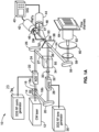
- FIG. 1A through FIG. 1D illustrate one embodiment 10 of utilizing FIRE for parallel flow cytometry using radiofrequency multiplexing according to the present disclosure.
- a laser 12 e.g., 488-nm excitation
- beamsplitter 16 e.g., non-polarizing
- the light in the first arm 18a is frequency shifted by an acousto-optic deflector (AOD) 22, which is driven by a phase-engineered radiofrequency comb 23, designed to minimize signal peak-to-average power ratio.
- AOD acousto-optic deflector
- this RF comb causes AOD 22 to generate multiple deflected optical beams 24 possessing a range of both output angles as well as frequency shifts. Output from AOD 24 is returned back for combination with the other arm by mirror 26.
- the RF comb generator prefferably configured to generate a spatially disparate amplitude modulated beam. If configured for collecting images, the frequencies in the comb are too closely spaced for analyzing separate flow streams. This configuration of the RF comb generator could be referred to as a 'sparse' frequency mode.
- the second arm of the interferometer has beam 18b reflected from mirror 20 to then be shifted in frequency using an acousto-optic frequency shifter (AOFS) 28 receiving a signal from a direct digital synthesis (DDS) radio-frequency (RF) tone generator 30 to generate a local oscillator (LO) beam 32.
- AOFS acousto-optic frequency shifter
- a cylindrical lens 33 placed after the AOFS matches the angular divergence of the LO arm to that of the RF comb beams.
- the two beams are focused 36 coincident to a line on the sample using a conventional laser scanning microscope lens system.
- Other configurations of one or more acousto-optic devices to generate frequency-shifted coincident pairs of beams are also disclosed.
- other system configurations such as multiple electro-optic, liquid crystal, or other light modulators can be employed to amplitude modulate multiple independent excitation optical beams at more than one unique frequency, such that a single PMT detector can be used to analyze the fluorescence or scatter emission from all flow channels simultaneously. optical beams.
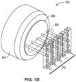
- FIG. 3 depicts a parallel flow through microfluidic channels, in which particles in those channels are all simultaneously detected/captured according to the presented technology.
- FIG. 3 depicts a parallel flow through microfluidic channels, in which particles in those channels are all simultaneously detected/captured according to the presented technology.
- a plurality of parallel flow channels each marked with the vertical flow arrow.
- the image was captured with only two particles in the channels.
- excitation and fluorescent response capture was performed using a similar setup to that of the disclosed technology.
- single-point flow cytometry measurements were performed on fluorescent beads.
- the FIRE setup shown in the figure excites two parallel microfluidic channels on a chip fabricated using polydimethylsiloxane (PDMS) molding.
- PDMS polydimethylsiloxane
- a single sample consisting of 1.0 ⁇ m ( ⁇ ex / ⁇ em 515/585 nm) and 2.2 ⁇ m ( ⁇ ex / ⁇ em 490/520 nm) fluorescent beads, was flowed through parallel channels at a mean velocity of 1 mls using a syringe pump.
- Channels 1 and 2 were excited using a 488 nm laser, modulated at beat frequencies of 10 and 50 MHz, respectively.
- FIG. 4A and FIG. 4B depict scatter plots for the 10 MHz and 50 MHz flow channels after raw data was thresholded and the fluorescence pulses were integrated to create PE (red) vs. FITC (green) fluorescence intensity scatter plot. It will be noted that these plots are shown as monochromatic to simplify reproduction of the patent application. The two bead populations in both channels are clearly resolved, despite the low (8-bit) resolution of the digitizer used to collect the data (no log amplification was used). This experiment was run at a total throughput of approximately 70,000 beads/second (35,000 beads/second/flow channel). This preliminary result clearly shows the ability of FIRE to perform 2-color parallel conventional flow cytometry using a single photomultiplier tube detector to detect each fluorescence color simultaneously from multiple flow channels.
- PMT detector is included in the final cytometer design.
- Backscatter detection can replace the conventional side-scatter detection channel, by using a PMT in a similar position to PMTs 42 and 44.
- FIRE operates by simultaneously exciting fluorescence from distinct points on the sample at a unique radiofrequency. Since the excitation (and hence, emission) from each point is tagged with a unique frequency, a single PMT can be used to collect epi-fluorescence from multiple spatial points, and a Fourier transform of the output signal is used to analyze the fluorescence emission of the sample, for example, of an array of parallel flow channels.
- the optical design is configured such that a plurality of discrete points (e.g., 10 discrete points) is illuminated by amplitude modulated beams or pairs of frequency-shifted beams.
- Illumination at the plurality of discrete points is a configuration to maximize the amount of laser power incident upon each flow channel, without wasting laser power on the regions between the flow channels, as would be the case when using an AOFS and cylindrical lens, although this embodiment of the system still enables analysis of multiple flow channels using single element detectors.
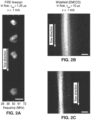
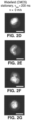
- FIG. 2A through FIG. 2G depict results from experiments using FIRE to perform imaging flow cytometry to show what fluorescence imaging can depict from a single particle in a stream.
- MCF-7 breast carcinoma cells are shown flowing in a microfluidic channel at a velocity of 1 m/s. All images are of MCF-7 breast carcinoma cells, stained with the DNA stain Syto16, taken using a 60x, 0.70-NA objective lens.
- FIG. 2A is seen representative FIRE images of cells flowing at a velocity of 1 m/s, taken using a pixel frequency spacing of 800 kHz, and 54 ⁇ W of 488-nm laser power per pixel, measured before the objective.
- FIG. 2C depict single 10- ⁇ s exposure frame transfer EMCCD images of individual cells flowing at a velocity of 1 m/s for comparison.
- the electron multiplier gain was adjusted to produce maximal image SNR, and the EMCCD vertical shift time was set to the minimum value of 564 ns. Blur is observed in the image due to the long exposure time and the frame transfer nature of the EMCCD.
- FIG. 2D through FIG. 2G wide field fluorescence images are represented of stationary MCF-7 cells for morphological reference. All scale bars are 10 ⁇ m.
- the present disclosure is not configured for performing imaging on cells in a single stream, but instead to simultaneously analyzing at least one discrete point in each of a plurality of flow streams. Examples of the types of information provided by the presented technology are described in FIG. 3 through FIG. 4B .
- the field of view, cell flow velocities, inertial focusing spatial distribution, and excitation laser spot sizes are designed for producing a combination of maximum throughput as well as maximum signal-to-noise ratio (SNR).
- the design goal is to record 10,000 events/second in each of a plurality of parallel channels (e.g., 10), all within a 1 mm field of view.
- a 488 nm laser is utilized for excitation, and existing digitizing electronics (e.g., 16-bit with memory depth capable of continuously storing data from more than 10 ⁇ 9 cells) are utilized to collect the data.
- digitizing electronics e.g., 16-bit with memory depth capable of continuously storing data from more than 10 ⁇ 9 cells
- Higher bit-depth commercially-available digitizers can be used for better intensity resolution, as desired.
- the laser power directed to each channel is adjusted, such as in software, by adjusting the MATLAB-generated waveform used to drive the acousto-optics.
- a 0.8-NA (or higher numerical aperture), 20x microscope objective is utilized to improve the detection sensitivity of the system (as compared to 0.45-NA, 20x).
- This parameter can be measured with the system of the present disclosure using standard techniques, and laser power can be increased to achieve this goal if not possible with a 100 mW 488 nm laser. More powerful lasers (e.g., greater than 1 W) exist that would further improve the sensitivity (dividing the power into 10 spots reduces the power per channel to approximately 50 mW per channel).
- microfluidic chips From previous testing templates have been evaluated for fabricating massively parallel microfluidic chips. The present disclosure can be utilized separately with these chips, which have walls in between each stream. A variety of microfluidic chip designs can be envisioned that will work with the frequency multiplexed nature of the FIRE parallel flow cytometer. It should also be appreciated that hydrodynamic focusing, inertial focusing, or other techniques and combinations thereof can be utilized in the flow channels to align the cells in a variety of positions for interrogation using modulated optical beams.
- FIG. 3 depicts a parallel flow through microfluidic channels, in which particles in those channels are all simultaneously detected/captured according to the presented technology.
- FIG. 3 depicts a parallel flow through microfluidic channels, in which particles in those channels are all simultaneously detected/captured according to the presented technology.
- a plurality of parallel flow channels each marked with the vertical flow arrow.
- the image was captured with only two particles in the channels.
- excitation and fluorescent response capture was performed using a similar setup to that of the disclosed technology.
- single-point flow cytometry measurements were performed on fluorescent beads.
- the FIRE setup shown in the figure excites two parallel microfluidic channels on a chip fabricated using polydimethylsiloxane (PDMS) molding.
- PDMS polydimethylsiloxane
- a single sample consisting of 1.0 ⁇ m ( ⁇ ex / ⁇ em 515/585 nm) and 2.2 ⁇ m ( ⁇ ex / ⁇ em 490/520 nm) fluorescent beads, was flowed through parallel channels at a mean velocity of 1 m/s using a syringe pump.
- Channels 1 and 2 were excited using a 488 nm laser, modulated at beat frequencies of 10 and 50 MHz, respectively.
- FIG. 4A and FIG. 4B depict scatter plots for the 10 MHz and 50 MHz flow channels after raw data was thresholded and the fluorescence pulses were integrated to create PE (red) vs. FITC (green) fluorescence intensity scatter plot. It will be noted that these plots are shown as monochromatic to simplify reproduction of the patent application. The two bead populations in both channels are clearly resolved, despite the low (8-bit) resolution of the digitizer used to collect the data (no log amplification was used). This experiment was run at a total throughput of approximately 70,000 beads/second (35,000 beads/second/flow channel). This preliminary result clearly shows the ability of FIRE to perform 2-color parallel conventional flow cytometry using a single photomultiplier tube detector to detect each fluorescence color simultaneously from multiple flow channels.
Claims (16)
- Vorrichtung zur gleichzeitigen Analyse von physikalischen und chemischen Eigenschaften von Partikeln in mehreren Strömen von Partikeln, wobei die Vorrichtung folgendes umfasst:(a) Mittel (70) für die Bildung einer Vielzahl von unabhängigen konzentrierten Strömen von Partikeln;(b) mindestens eine optische Anregungsquelle (12);(c) eine erste Hochfrequenzquelle (24) mit einem ersten Hochfrequenzausgang;(d) eine zweite Hochfrequenzquelle (30) mit einem zweiten Hochfrequenzausgang;(e) eine optische oder akustooptische Kombinationsvorrichtung (16, 20, 22, 26, 28, 34), die für die Verbindung des ersten Hochfrequenzausgangs und des zweiten Hochfrequenzausgangs zu einem optischen Abfragestrahl (36) mit einer räumlich verteilten Taktfrequenz gestaltet ist;(f) ein optisches System (38, 56, 58, 60, 62), das für die Lenkung des optischen Abfragestrahls (36) mit einer räumlich verteilten Taktfrequenz über die Vielzahl von konzentrierten Strömen von Partikeln gestaltet ist, so dass die räumlich verteilte Taktfrequenz die Vielzahl von konzentrierten Strömen von Partikeln gleichzeitig überspannt; und(g) einen optischen Detektor (42, 44), der für die Erfassung der gleichzeitigen Fluoreszenz von Partikeln innerhalb der Vielzahl von konzentrierten Strömen von Partikeln bei unterschiedlichen Modulationsfrequenzen innerhalb der räumlich verteilten Taktfrequenz gestaltet ist.
- Vorrichtung nach Anspruch 1, wobei die optische Anregungsquelle (12) einen Laser umfasst.
- Vorrichtung nach Anspruch 2, wobei der Laser (12) einen Dauerstrichlaser umfasst.
- Vorrichtung nach Anspruch 1, wobei die optische Kombinationsvorrichtung (16, 20, 22, 26, 28, 34), das optische System (38, 56, 58, 60, 62) oder eine Kombination daraus für die selbstständige Steuerung einer Beleuchtung, die auf jede parallele Strömung gerichtet ist, um jeden Strömungskanal mit einer identischen optischen Empfindlichkeit zu errichten, gestaltet ist.
- Vorrichtung nach Anspruch 1, wobei die Vielzahl von konzentrierten Strömen von Partikeln in einer Mikrofluidikvorrichtung oder einem Mikrofluidikchip zurückgehalten werden.
- Vorrichtung nach Anspruch 1, die ferner einen oder mehrere zusätzliche optische Detektoren (42, 44) umfasst, von denen jeder für die Erfassung der Fluoreszenz bei einer unterschiedlichen Modulationsfrequenz gestaltet ist, so dass unterschiedliche Eigenschaften von Partikeln in jedem konzentrierten Strom erkannt werden.
- Vorrichtung nach Anspruch 6, die ferner optische Mittel (50) für die Unterscheidung unterschiedlicher Farben der Fluoreszenzemission umfasst, so dass jeder dieser mehreren Detektoren (42, 44) die Fluoreszenz in einem unterschiedlichen Spektralband, das mit unterschiedlichen Eigenschaften von Partikeln verbunden ist, in jedem konzentrierten Strom von Partikeln analysieren kann.
- Vorrichtung nach Anspruch 1, wobei jeder Kanal (70) einer Mikrofluidikvorrichtung oder eines Mikrofluidikchips einer Anregung bei einer unterschiedlichen Modulationsfrequenz ausgesetzt ist, die für diesen Kanal (70) durch den Einsatz einer Taktfrequenzmodulation eindeutig ist.
- Vorrichtung nach Anspruch 8, wobei die Fluoreszenz in jedem Kanal (70) mit einer bestimmten Hochfrequenz angeregt wird, was die Messung der Fluoreszenz von mehreren Stellen unter Einsatz eines einzelnen Photodetektors ermöglicht.
- Vorrichtung nach Anspruch 1, wobei die Partikel Zellen oder Teile von Zellen umfassen.
- Vorrichtung nach Anspruch 1, wobei die optische oder akustooptische Kombinationsvorrichtung (16, 20, 22, 26, 28, 34) ein Interferometer umfasst, bei dem der Strahl in einen ersten Arm (18a) des Strahls, der von einem ersten akustooptischen Gerät (22) empfangen wird, und einen zweiten Arm des Strahls (18b), der von einem zweiten akustooptischen Gerät (28) empfangen wird, aufgeteilt wird, wonach die Arme des Strahls wiederverbunden und durch das optische System gelenkt werden.
- Vorrichtung nach Anspruch 11, wobei die erste oder zweite akustooptische Vorrichtung einen akustooptischen Deflektor (22) oder einen akustooptischen Frequenzwechsler (28) umfasst.
- Vorrichtung nach Anspruch 12, die ferner einen Hochfrequenz-Kammgenerator (24) umfasst, der für den Antrieb des akustooptischen Deflektors gestaltet ist und somit eine Reihe von räumlich getrennten amplitudenmodulierten Strahlen durch Taktfrequenzmodulation mit einer ausreichenden räumlichen Breite zur Überspannung der Vielzahl von konzentrierten Strömen von Partikeln erzeugt.
- Vorrichtung nach Anspruch 1, die ferner Digitalisierungselektronik (40) umfasst, die für das Speichern von Daten zu der erfassten Fluoreszenz von Partikeln gestaltet ist, um die Analyse von Partikeleigenschaften zu ermöglichen.
- Verfahren zur gleichzeitigen Abfrage von physikalischen und chemischen Eigenschaften von Partikeln in mehreren Strömen von Partikeln unter Einsatz der Vorrichtung zur gleichzeitigen Analyse von physikalischen und chemischen Eigenschaften von Partikeln in mehreren Strömen von Partikeln gemäß einem der Ansprüche 1-14, wobei das Verfahren folgendes umfasst:(a) Bildung einer Vielzahl von unabhängigen konzentrierten Strömen von Partikeln durch die Einführung von fluidischen Partikeln oder Zellen als Ziele in eine Vielzahl von Fluidströmungskanälen (70);(b) Bestrahlung durch die mindestens eine optische Anregungsquelle der einzelnen Fluidströmungskanäle (70) mit einem optischen Abfragestrahl mit einer räumlich verteilten Taktfrequenz, wobei der optische Abfragestrahl eine Vielzahl von separaten Stahlen umfasst, die so gestaltet sind, dass sie auf jeden einzelnen der Vielzahl von konzentrierten Strömen gerichtet sind, und wobei der optische Abfragestrahl von dem optischen System gelenkt wird, so dass die räumlich verteilte Strahlungsfrequenz gleichzeitig die Vielzahl von konzentrierten Strömen von Partikeln, deren physikalischen und chemischen Eigenschaften analysiert werden, überspannt, so dass Ziele in jedem Fluidströmungskanal (70) einem unterschiedlichen modulierten optischen Strahl mit einer Modulationsfrequenz, die für diesen Fluidströmungskanal (70) eindeutig ist, ausgesetzt sind, wobei jeder Strahl des frequenzverschobenen Lichts des optischen Abfragestrahls durch Bestrahlung der optischen oder akustooptischen Kombinationsvorrichtung (16, 20, 22, 26, 28, 34) erzeugt wird, die für die Kombination eines ersten Hochfrequenzausgangs von der ersten Hochfrequenzquelle (24) und eines zweiten Hochfrequenzausgangs von der zweiten Hochfrequenzquelle (30) gestaltet ist;(c) Erkennen mit Hilfe des optischen Detektors (42, 44) der Fluoreszenz von den Zielen in jedem Fluidströmungskanal (70) parallel auf Basis der von dem optischen Detektor (42, 44) festgestellten Anregung bei einer bestimmten Modulationsfrequenz; und(d) Ausgabe der Fluoreszenzdaten für die Analyse von physikalischen und chemischen Eigenschaften der Ziele in den Fluidströmungskanälen (70).
- Verfahren nach Anspruch 15, wobei die gleichzeitige Abfrage der physikalischen und chemischen Eigenschaften von Partikeln in mehreren Strömen von Partikeln Bestandteil des Verfahrens der Durchflusszytometrie ist, und wobei einer des ersten Hochfrequenzausgangs und des zweiten Hochfrequenzausgangs ein Hochfrequenzkamm ist.
Priority Applications (1)
| Application Number | Priority Date | Filing Date | Title |
|---|---|---|---|
| EP23179749.9A EP4253936A3 (de) | 2014-03-18 | 2015-03-18 | Paralleles durchflusszytometer unter verwendung von funkfrequenz-mulitplexing, und verfahren |
Applications Claiming Priority (2)
| Application Number | Priority Date | Filing Date | Title |
|---|---|---|---|
| US201461955137P | 2014-03-18 | 2014-03-18 | |
| PCT/US2015/021264 WO2015143041A1 (en) | 2014-03-18 | 2015-03-18 | Parallel flow cytometer using radiofrequency mulitplexing |
Related Child Applications (2)
| Application Number | Title | Priority Date | Filing Date |
|---|---|---|---|
| EP23179749.9A Division-Into EP4253936A3 (de) | 2014-03-18 | 2015-03-18 | Paralleles durchflusszytometer unter verwendung von funkfrequenz-mulitplexing, und verfahren |
| EP23179749.9A Division EP4253936A3 (de) | 2014-03-18 | 2015-03-18 | Paralleles durchflusszytometer unter verwendung von funkfrequenz-mulitplexing, und verfahren |
Publications (3)
| Publication Number | Publication Date |
|---|---|
| EP3120130A1 EP3120130A1 (de) | 2017-01-25 |
| EP3120130A4 EP3120130A4 (de) | 2017-11-08 |
| EP3120130B1 true EP3120130B1 (de) | 2023-07-26 |
Family
ID=54145272
Family Applications (2)
| Application Number | Title | Priority Date | Filing Date |
|---|---|---|---|
| EP23179749.9A Pending EP4253936A3 (de) | 2014-03-18 | 2015-03-18 | Paralleles durchflusszytometer unter verwendung von funkfrequenz-mulitplexing, und verfahren |
| EP15764027.7A Active EP3120130B1 (de) | 2014-03-18 | 2015-03-18 | Paralleles durchflusszytometer unter verwendung von funkfrequenz-mulitplexing, und verfahren |
Family Applications Before (1)
| Application Number | Title | Priority Date | Filing Date |
|---|---|---|---|
| EP23179749.9A Pending EP4253936A3 (de) | 2014-03-18 | 2015-03-18 | Paralleles durchflusszytometer unter verwendung von funkfrequenz-mulitplexing, und verfahren |
Country Status (5)
| Country | Link |
|---|---|
| US (9) | US9784661B2 (de) |
| EP (2) | EP4253936A3 (de) |
| JP (1) | JP6691053B2 (de) |
| ES (1) | ES2959506T3 (de) |
| WO (1) | WO2015143041A1 (de) |
Families Citing this family (38)
| Publication number | Priority date | Publication date | Assignee | Title |
|---|---|---|---|---|
| EP4253936A3 (de) | 2014-03-18 | 2024-03-20 | The Regents of The University of California | Paralleles durchflusszytometer unter verwendung von funkfrequenz-mulitplexing, und verfahren |
| US10078045B2 (en) | 2015-10-13 | 2018-09-18 | Omega Biosystems Incorporated | Multi-modal fluorescence imaging flow cytometry system |
| EP3430376A1 (de) * | 2016-03-17 | 2019-01-23 | BD Biosciences | Zellsortierung mit einem hochdurchsatz-fluoreszenzdurchflusszytometer |
| CN105717035B (zh) * | 2016-04-08 | 2019-04-23 | 清华大学 | 流式细胞术检测装置和方法 |
| WO2017197271A1 (en) | 2016-05-12 | 2017-11-16 | Bd Biosciences | Fluorescence imaging flow cytometry with enhanced image resolution |
| ES2951466T3 (es) | 2016-09-13 | 2023-10-23 | Becton Dickinson Co | Citómetro de flujo con ecualización óptica |
| FR3077639B1 (fr) * | 2018-02-02 | 2020-02-14 | Universite De Rennes 1 | Methode de determination d'une vitesse de sedimentation |
| WO2019210062A1 (en) * | 2018-04-27 | 2019-10-31 | Becton, Dickinson And Company | Methods and apparatuses for image control and display of particle analyzer images |
| US11181464B2 (en) | 2018-06-19 | 2021-11-23 | Becton, Dickinson And Company | Variable multiplexing switches for detector arrays, systems and methods of use thereof |
| WO2020005430A1 (en) | 2018-06-28 | 2020-01-02 | Becton, Dickinson And Company | Integrated pre-amplification light detection systems and methods of use thereof |
| JP2021534401A (ja) | 2018-08-15 | 2021-12-09 | ベクトン・ディキンソン・アンド・カンパニーBecton, Dickinson And Company | フロー式粒子分析器のための流量および真空制御式流体管理システム |
| CN112996900A (zh) * | 2018-09-14 | 2021-06-18 | 加利福尼亚大学董事会 | 细胞分选装置及方法 |
| HUE064220T2 (hu) * | 2018-09-14 | 2024-02-28 | Max Planck Gesellschaft | Részecskeelemzõ módszer és berendezés spektrometria alapú részecskeelmezéshez |
| US11035776B2 (en) | 2018-10-30 | 2021-06-15 | Becton, Dickinson And Company | Particle sorting module with alignment window, systems and methods of use thereof |
| CN113439205A (zh) | 2018-12-28 | 2021-09-24 | 贝克顿·迪金森公司 | 用于对样本的荧光团进行光谱解析的方法及其系统 |
| CN113302470A (zh) | 2019-02-08 | 2021-08-24 | 贝克顿·迪金森公司 | 液滴分选决策模块、系统及其使用方法 |
| CN109709025B (zh) * | 2019-02-12 | 2021-07-16 | 军事科学院系统工程研究院卫勤保障技术研究所 | 一种多模成像光学系统 |
| JP7465273B2 (ja) * | 2019-03-21 | 2024-04-10 | ベクトン・ディキンソン・アンド・カンパニー | 光検出システム及びその使用方法 |
| US11268890B2 (en) | 2019-03-29 | 2022-03-08 | Becton, Dickinson And Company | Parameters for use in particle discrimination |
| US11275026B2 (en) | 2019-05-14 | 2022-03-15 | Becton, Dickinson And Company | Phase-calibration for imaging flow cytometry |
| WO2020243475A1 (en) | 2019-05-30 | 2020-12-03 | Becton, Dickinson And Company | Phase-correction of radiofrequency-multiplexed signals |
| JP2022540601A (ja) | 2019-07-10 | 2022-09-16 | ベクトン・ディキンソン・アンド・カンパニー | 細胞選別分類を調整するための再構成可能な集積回路 |
| US11635375B2 (en) | 2019-11-20 | 2023-04-25 | Becton, Dickinson And Company | Light detection module with adjustable sensitivity |
| WO2021154579A1 (en) | 2020-01-31 | 2021-08-05 | Becton, Dickinson And Company | Methods and systems for adjusting a training gate to accommodate flow cytometer data |
| US11821830B2 (en) | 2020-02-07 | 2023-11-21 | Becton, Dickinson And Company | Clustered wavelength division light detection systems and methods of using the same |
| JP2023516193A (ja) | 2020-02-26 | 2023-04-18 | ベクトン・ディキンソン・アンド・カンパニー | 二次光散乱検出器を有する光検出システムおよびその使用方法 |
| CN115176142A (zh) | 2020-02-27 | 2022-10-11 | 贝克顿·迪金森公司 | 用于在细胞分选中标识饱和数据信号的方法及用于其的系统 |
| JP2023518457A (ja) | 2020-03-17 | 2023-05-01 | ベクトン・ディキンソン・アンド・カンパニー | 光検出のための利得一致した増幅器 |
| JP2023524474A (ja) | 2020-04-28 | 2023-06-12 | ベクトン・ディキンソン・アンド・カンパニー | 独特な表現型を指標選別するための方法及び同システム |
| CN115917293A (zh) | 2020-04-29 | 2023-04-04 | 贝克顿·迪金森公司 | 在流式细胞仪中调节和同步检测的方法及系统 |
| EP4147029A4 (de) | 2020-05-06 | 2023-11-01 | Becton, Dickinson and Company | Verfahren und systeme zur charakterisierung von überlaufstreuung in durchflusszytometerdaten |
| US11513058B2 (en) | 2020-05-19 | 2022-11-29 | Becton, Dickinson And Company | Methods for modulating an intensity profile of a laser beam and systems for same |
| CN111707975B (zh) * | 2020-06-24 | 2022-09-02 | 中国电子科技集团公司第四十一研究所 | 一种适用于氦光泵磁力仪的射频信号发生系统及方法 |
| JP2023532895A (ja) | 2020-06-26 | 2023-08-01 | ベクトン・ディキンソン・アンド・カンパニー | フローストリーム中の試料を照射するためのデュアル励起ビーム、及びそれを使用するための方法 |
| CN113390844A (zh) * | 2021-06-17 | 2021-09-14 | 中国药科大学 | 多尺度光纤荧光显微成像系统 |
| US20230053122A1 (en) | 2021-08-10 | 2023-02-16 | Becton, Dickinson And Company | Clamps for operably coupling an optical component to a mounting block, and methods and systems for using the same |
| US20230046207A1 (en) | 2021-08-10 | 2023-02-16 | Becton, Dickinson And Company | Outlet fittings for reducing bubbles at the interface with a flow cell, and flow cytometers and methods using the same |
| CN114112864A (zh) * | 2021-11-22 | 2022-03-01 | 西北大学 | 一种生物样本的计数、分选与测速系统、方法及存储介质 |
Citations (1)
| Publication number | Priority date | Publication date | Assignee | Title |
|---|---|---|---|---|
| US20070087445A1 (en) * | 2005-10-14 | 2007-04-19 | The General Hospital Corporation | Arrangements and methods for facilitating photoluminescence imaging |
Family Cites Families (126)
| Publication number | Priority date | Publication date | Assignee | Title |
|---|---|---|---|---|
| US3854050A (en) | 1973-09-11 | 1974-12-10 | Department Of Health Education | High precision fluorometer for measuring enzymatic substrates in tissue |
| US4545677A (en) | 1984-03-05 | 1985-10-08 | Becton, Dickinson And Company | Prismatic beam expander for light beam shaping in a flow cytometry apparatus |
| DE3610396A1 (de) | 1986-03-27 | 1987-10-01 | Wella Ag | Mittel und verfahren zur oxidativen faerbung von haaren |
| JPH0810306B2 (ja) | 1990-01-26 | 1996-01-31 | 大日本スクリーン製造株式会社 | 光ビームの偏向制御方法 |
| US5204884A (en) | 1991-03-18 | 1993-04-20 | University Of Rochester | System for high-speed measurement and sorting of particles |
| DE69132273D1 (de) * | 1990-10-10 | 2000-08-03 | Univ Maryland | Verfahren und vorrichtung zur bestimmung von lebensdauer von fluoreszenz in der durchflusscytometrie |
| WO1992013265A1 (en) * | 1991-01-24 | 1992-08-06 | The University Of Maryland | Method and apparatus for multi-dimensional phase fluorescence lifetime imaging |
| US5203339A (en) | 1991-06-28 | 1993-04-20 | The Government Of The United States Of America As Represented By The Secretary Of The Department Health And Human Services | Method and apparatus for imaging a physical parameter in turbid media using diffuse waves |
| US5309912A (en) | 1991-11-08 | 1994-05-10 | The United States Of America As Represented By The Secretary Of The Department Of Health And Human Services | Multidimensional imaging using a single point detector for a phase encoded modulated optical carrier |
| US5192870A (en) | 1992-01-14 | 1993-03-09 | International Business Machines Corporation | Optical submicron aerosol particle detector |
| US5255257A (en) | 1992-03-04 | 1993-10-19 | Lasertape Systems, Inc. | Frequency, phase and amplitude control apparatus and method for acousto-optic deflector optimization |
| US6057814A (en) | 1993-05-24 | 2000-05-02 | Display Science, Inc. | Electrostatic video display drive circuitry and displays incorporating same |
| US5296911A (en) | 1992-07-16 | 1994-03-22 | Schiapparelli Biosystems, Inc. | Optical test system for a chemical analyzer |
| US5270548A (en) | 1992-07-31 | 1993-12-14 | The United States Of America As Represented By The United States Department Of Energy | Phase-sensitive flow cytometer |
| US5293213A (en) | 1992-08-12 | 1994-03-08 | Klein Uwe K A | Utilization of a modulated laser beam in heterodyne interferometry |
| US5483469A (en) | 1993-08-02 | 1996-01-09 | The Regents Of The University Of California | Multiple sort flow cytometer |
| US5489977A (en) | 1993-08-11 | 1996-02-06 | Texaco Inc. | Photomeric means for monitoring solids and fluorescent material in waste water using a falling stream water sampler |
| JPH0961858A (ja) | 1995-08-28 | 1997-03-07 | Minolta Co Ltd | 音響光学光走査装置 |
| US5968738A (en) | 1995-12-06 | 1999-10-19 | The Board Of Trustees Of The Leland Stanford Junior University | Two-reporter FACS analysis of mammalian cells using green fluorescent proteins |
| JPH10148778A (ja) * | 1996-11-18 | 1998-06-02 | Minolta Co Ltd | マルチビーム発生装置 |
| DE19721882C2 (de) | 1997-05-26 | 1999-04-29 | Bosch Gmbh Robert | Interferometrische Meßvorrichtung |
| DE19721881C2 (de) | 1997-05-26 | 1999-05-20 | Bosch Gmbh Robert | Interferometrische Meßvorrichtung |
| US6031852A (en) | 1997-05-30 | 2000-02-29 | The Regents Of The University Of California | Rapid acoustooptic tuner and phase-shifter |
| US6016196A (en) | 1997-06-17 | 2000-01-18 | Massachusetts Institute Of Technology | Multiple beam pair optical imaging |
| US6236454B1 (en) | 1997-12-15 | 2001-05-22 | Applied Materials, Inc. | Multiple beam scanner for an inspection system |
| US6642018B1 (en) | 1998-03-27 | 2003-11-04 | Oncosis Llc | Method for inducing a response in one or more targeted cells |
| WO1999058955A1 (en) * | 1998-05-14 | 1999-11-18 | Luminex Corporation | Multi-analyte diagnostic system and computer implemented process for same |
| US6271924B1 (en) | 1998-12-29 | 2001-08-07 | Bryan Kok Ann Ngoi | Noncontact acoustic optic scanning laser vibrometer for determining the difference between an object and a reference surface |
| CA2375530A1 (en) | 1999-06-23 | 2000-12-28 | Patrick Toomey | Water detection and source identification methods for structures using electromagnetic radiation spectroscopy |
| US6396069B1 (en) | 1999-06-25 | 2002-05-28 | Macpherson David C. | Topographer for real time ablation feedback having synthetic wavelength generators |
| US7630063B2 (en) * | 2000-08-02 | 2009-12-08 | Honeywell International Inc. | Miniaturized cytometer for detecting multiple species in a sample |
| US6778263B2 (en) | 2000-08-25 | 2004-08-17 | Amnis Corporation | Methods of calibrating an imaging system using calibration beads |
| JP2002296178A (ja) * | 2001-03-30 | 2002-10-09 | Shimadzu Corp | フローセル検出器 |
| US6636623B2 (en) | 2001-08-10 | 2003-10-21 | Visiongate, Inc. | Optical projection imaging system and method for automatically detecting cells with molecular marker compartmentalization associated with malignancy and disease |
| FR2830629B1 (fr) | 2001-10-04 | 2004-01-09 | Commissariat Energie Atomique | Procede et dispositif de prelevement d'une partie d'un faisceau lumineux, notamment pour appareil d'analyse de fluorescence |
| DE20216583U1 (de) | 2001-12-20 | 2003-01-23 | Leica Microsystems | Mikroskop und Durchflusszytometer |
| US6868347B2 (en) | 2002-03-19 | 2005-03-15 | The Regents Of The University Of California | System for real time, non-invasive metrology of microfluidic chips |
| US20040002154A1 (en) | 2002-04-19 | 2004-01-01 | Palsson Bernhard O. | Methods for preparing libraries of unique tags and related screening methods |
| US20060014212A1 (en) | 2002-05-10 | 2006-01-19 | Epitome Biosystems, Inc. | Proteome epitope tags and methods of use thereof in protein modification analysis |
| DE10225838B4 (de) | 2002-06-11 | 2021-10-21 | Leica Microsystems Cms Gmbh | Verfahren zur Scanmikroskopie, Scanmikroskop und Vorrichtung zum Codieren eines Beleuchtungslichtstrahles |
| GB2401431B (en) | 2003-04-02 | 2005-04-27 | Amersham Biosciences Uk Ltd | Method of, and computer software for, classification of cells into subpopulations |
| CA2536360C (en) | 2003-08-28 | 2013-08-06 | Celula, Inc. | Methods and apparatus for sorting cells using an optical switch in a microfluidic channel network |
| US7803624B2 (en) | 2003-09-30 | 2010-09-28 | Cytyc Corporation | Automated cytological sample classification |
| US7103402B2 (en) | 2003-10-02 | 2006-09-05 | Ut-Battelle, Llc | Advanced synchronous luminescence imaging for chemical and medical diagnostics |
| US7590991B2 (en) | 2003-10-09 | 2009-09-15 | Terayon Communication Systems, Inc. | Method and apparatus for determining channel to which a TV or VCR is tuned |
| EP3009815B1 (de) | 2003-10-27 | 2022-09-07 | The General Hospital Corporation | Verfahren und vorrichtung zur durchführung optischer abbildung mit frequenzdomäneninterferometrie |
| DE10357584B4 (de) | 2003-12-08 | 2006-06-14 | Leica Microsystems Cms Gmbh | Verfahren zum Trennen unterschiedlicher Emissionswellenlängen in einem Scanmikroskop |
| US7019891B2 (en) | 2004-06-07 | 2006-03-28 | Electro Scientific Industries, Inc. | AOM modulation techniques employing plurality of tilt-angled transducers to improve laser system performance |
| WO2006105096A2 (en) | 2005-03-29 | 2006-10-05 | Integral Orthopedics Inc. | Inter-scapular bolster |
| EP1928306B1 (de) | 2005-09-29 | 2021-01-13 | General Hospital Corporation | OPTISCHES KOHÄRENZTOMOGRAFIESYSTEME UND VERFAHREN MIT MIKROSKOPISCHER Fluoreszensbildgebung VON EINER ODER MEHR BIOLOGISCHEN STRUKTUREN |
| GB0525072D0 (en) | 2005-12-09 | 2006-01-18 | Enigma Diagnostics Ltd | Fluorescence-based detection methods and apparatus |
| EP1991887B1 (de) | 2006-02-17 | 2018-10-17 | Regents of the University of Minnesota | Hochfeld-magnetresonanz |
| US20090323061A1 (en) | 2006-02-28 | 2009-12-31 | Lukas Novotny | Multi-color hetereodyne interferometric apparatus and method for sizing nanoparticles |
| JP2007285999A (ja) * | 2006-04-20 | 2007-11-01 | Furukawa Electric Co Ltd:The | 光測定装置 |
| CA2652027C (en) | 2006-05-12 | 2017-06-06 | Immunivest Corporation | A laser illumination system in fluorescent microscopy |
| EP1862838B1 (de) | 2006-05-29 | 2009-08-19 | Olympus Corporation | Laserscan-Mikroskop und mikroskopisches Überwachungsverfahren |
| JP5133600B2 (ja) | 2006-05-29 | 2013-01-30 | オリンパス株式会社 | レーザ走査型顕微鏡および顕微鏡観察方法 |
| JP2008007652A (ja) | 2006-06-29 | 2008-01-17 | Fujifilm Corp | アゾ色素、感熱転写記録用インクシート、感熱転写記録方法、カラートナー、インクジェット用インクおよびカラーフィルタ |
| US7697885B2 (en) | 2006-09-15 | 2010-04-13 | Aeroflex High Speed Test Solutions, Inc. | Multi-band jammer |
| JP2008089395A (ja) | 2006-10-02 | 2008-04-17 | Honda Instrument Service Co Ltd | 光触媒計及び光能力測定方法並びにそれに用いるセンサヘッド |
| US7804594B2 (en) | 2006-12-29 | 2010-09-28 | Abbott Laboratories, Inc. | Method and apparatus for rapidly counting and identifying biological particles in a flow stream |
| US7400457B1 (en) | 2007-01-04 | 2008-07-15 | Stockeryale Canada Inc. | Rectangular flat-top beam shaper |
| US8101426B2 (en) | 2007-03-02 | 2012-01-24 | Icyt Mission Technology, Inc. | System and method for the measurement of multiple fluorescence emissions in a flow cytometry system |
| US8290625B2 (en) | 2007-04-04 | 2012-10-16 | Beckman Coulter, Inc. | Flow cytometer sorter |
| JP5619344B2 (ja) | 2007-05-04 | 2014-11-05 | マツクス−プランク−ゲゼルシャフト ツール フエルデルング デル ヴイツセンシャフテン エー フアウ | モノリシックマイクロ共振器を使用した光周波数コム発生のための装置と方法 |
| US7982944B2 (en) | 2007-05-04 | 2011-07-19 | Max-Planck-Gesellschaft Zur Forderung Der Wissenschaften E.V. | Method and apparatus for optical frequency comb generation using a monolithic micro-resonator |
| US20100233676A1 (en) | 2007-06-14 | 2010-09-16 | Kimberly Kelly | High affinity fluorochrome binding peptides |
| WO2009009081A2 (en) | 2007-07-10 | 2009-01-15 | Massachusetts Institute Of Technology | Tomographic phase microscopy |
| JP4509163B2 (ja) * | 2007-10-26 | 2010-07-21 | ソニー株式会社 | 微小粒子の測定方法 |
| US8159670B2 (en) | 2007-11-05 | 2012-04-17 | Abbott Laboratories | Method and apparatus for rapidly counting and identifying biological particles in a flow stream |
| US9451884B2 (en) | 2007-12-13 | 2016-09-27 | Board Of Trustees Of The University Of Arkansas | Device and method for in vivo detection of clots within circulatory vessels |
| GB0800333D0 (en) | 2008-01-09 | 2008-02-20 | Ucl Business Plc | Beam deflection apparatus and methods |
| US20090219607A1 (en) | 2008-01-17 | 2009-09-03 | Baylor College Of Medicine | Method and apparatus for enhanced resolution microscopy of living biological nanostructures |
| US8565861B2 (en) | 2008-05-02 | 2013-10-22 | Olympus Corporation | Optical inspection device, electromagnetic wave detection method, electromagnetic wave detection device, organism observation method, microscope, endoscope, and optical tomographic image generation device |
| WO2009149733A1 (en) | 2008-06-13 | 2009-12-17 | Embl Heidelberg | Next generation flow cytometer sorter |
| US8184279B2 (en) | 2008-06-16 | 2012-05-22 | The Regents Of The University Of Colorado, A Body Corporate | Fourier domain sensing |
| CN102150035A (zh) | 2008-09-19 | 2011-08-10 | 三井造船株式会社 | 采用强度调制激光的荧光检测装置和荧光检测方法 |
| EP2340429B1 (de) | 2008-10-14 | 2022-08-24 | Tissuevision, Inc. | Vorrichtungen und verfahren für direktabtastende analoge zeitaufgelöse detektion |
| US8440952B2 (en) | 2008-11-18 | 2013-05-14 | The Regents Of The University Of California | Methods for optical amplified imaging using a two-dimensional spectral brush |
| TWI523720B (zh) | 2009-05-28 | 2016-03-01 | 伊雷克托科學工業股份有限公司 | 應用於雷射處理工件中的特徵的聲光偏轉器及相關雷射處理方法 |
| EP2267430A1 (de) | 2009-06-24 | 2010-12-29 | Masterrind GmbH | Vorrichtung und Verfahren zur Selektion von Partikeln |
| WO2011023593A1 (en) | 2009-08-24 | 2011-03-03 | INSERM (Institut National de la Santé et de la Recherche Médicale) | Method of and apparatus for imaging a cellular sample |
| GB0919854D0 (en) | 2009-11-12 | 2009-12-30 | Stfc Science & Technology | Detecting species in a dilute medium |
| JP5649828B2 (ja) | 2010-02-03 | 2015-01-07 | オリンパス株式会社 | レーザ顕微鏡装置 |
| WO2011097032A1 (en) * | 2010-02-05 | 2011-08-11 | Cytonome/St, Llc | Multiple flow channel particle analysis system |
| JP2011163787A (ja) * | 2010-02-05 | 2011-08-25 | Sony Corp | 微小粒子分析装置及び微小粒子分析方法 |
| JP5551477B2 (ja) | 2010-03-15 | 2014-07-16 | オリンパス株式会社 | 光源装置およびレーザ走査型顕微鏡装置 |
| US9101573B2 (en) | 2010-05-04 | 2015-08-11 | Virginia Tech Intellectual Properties, Inc. | Lanthionine synthetase component C-like proteins as molecular targets for preventing and treating diseases and disorders |
| JP2012008055A (ja) | 2010-06-25 | 2012-01-12 | Olympus Corp | 画像解析方法および画像解析装置 |
| US8384045B2 (en) | 2010-07-01 | 2013-02-26 | Sony Corporation | Minute particle analyzing device and method |
| SG10201912164UA (en) | 2010-11-16 | 2020-02-27 | 1087 Systems Inc | System for identifying and sorting living cells |
| DE102010044013A1 (de) | 2010-11-16 | 2012-05-16 | Carl Zeiss Microimaging Gmbh | Tiefenauflösungsgesteigerte Mikroskopie |
| US9066657B2 (en) | 2010-11-23 | 2015-06-30 | General Electric Company | Methods and systems of optical imaging for target detection in a scattering medium |
| CA2826544C (en) | 2011-02-04 | 2020-06-30 | Cytonome/St, Llc | Particle sorting apparatus and method |
| WO2012127907A1 (ja) | 2011-03-18 | 2012-09-27 | 独立行政法人理化学研究所 | 非線形光学顕微鏡および非線形光学顕微鏡法 |
| WO2012158727A2 (en) | 2011-05-16 | 2012-11-22 | Oewaves, Inc. | Generation of single optical tone, rf oscillation signal and optical comb in a triple-oscillator device based on nonlinear optical resonator |
| US8772039B2 (en) | 2011-05-26 | 2014-07-08 | The General Hospital Corporation | Optical thromboelastography system and method for evaluation of blood coagulation metrics |
| WO2013011001A1 (en) | 2011-07-19 | 2013-01-24 | Ovizio Imaging Systems N.V. | A method and system for detecting and/or classifying cancerous cells in a cell sample |
| US9664702B2 (en) | 2011-09-25 | 2017-05-30 | Theranos, Inc. | Fluid handling apparatus and configurations |
| JP5870851B2 (ja) | 2012-05-29 | 2016-03-01 | ソニー株式会社 | 情報処理装置、情報処理方法、及びプログラム |
| WO2014031985A1 (en) | 2012-08-24 | 2014-02-27 | The Trustees Of Dartmouth College | Method and apparatus for magnetic susceptibility tomography, magnetoencephalography, and taggant or contrast agent detection |
| CN110579435B (zh) | 2012-10-15 | 2023-09-26 | 纳诺赛莱克特生物医药股份有限公司 | 颗粒分选的系统、设备和方法 |
| ES2845600T3 (es) | 2013-01-09 | 2021-07-27 | Univ California | Aparato y métodos para la obtención de imágenes de fluorescencia utilizando excitación multiplexada por radiofrecuencia |
| EP4134656A1 (de) | 2013-03-14 | 2023-02-15 | Cytonome/ST, LLC | Anordnungen und verfahren zur verringerung des optischen übersprechens in partikelverarbeitungssystemen |
| GB201305317D0 (en) | 2013-03-22 | 2013-05-08 | Iles Raymond K | Prenatal screening for fetal abnormalities and disorders of pregnancy |
| US9372143B2 (en) | 2013-05-15 | 2016-06-21 | Captl Llc | Scanning image flow cytometer |
| JP6257312B2 (ja) | 2013-12-24 | 2018-01-10 | オリンパス株式会社 | 顕微鏡システム |
| US9538926B2 (en) | 2013-12-26 | 2017-01-10 | Fundacio Institut De Ciencies Fotoniques | Speckle contrast optical tomography |
| CN103762487B (zh) | 2014-01-04 | 2016-05-25 | 天津奇谱光电技术有限公司 | 一种具有双输出光束的可调谐激光器 |
| JP6214402B2 (ja) | 2014-01-07 | 2017-10-18 | オリンパス株式会社 | 光刺激装置および顕微鏡システム |
| US10451482B2 (en) | 2014-02-14 | 2019-10-22 | Palo Alto Research Center Incorporated | Determination of color characteristics of objects using spatially modulated light |
| EP4253936A3 (de) | 2014-03-18 | 2024-03-20 | The Regents of The University of California | Paralleles durchflusszytometer unter verwendung von funkfrequenz-mulitplexing, und verfahren |
| WO2015168026A2 (en) | 2014-04-28 | 2015-11-05 | The Broad Institute, Inc. | Method for label-free image cytometry |
| WO2016054293A1 (en) | 2014-09-30 | 2016-04-07 | The Regents Of The University Of California | Imaging flow cytometer using spatial-temporal transformation |
| JP6652559B2 (ja) | 2014-11-12 | 2020-02-26 | オーボテック リミテッド | 光学装置及び光学方法 |
| WO2017053592A1 (en) | 2015-09-23 | 2017-03-30 | The Regents Of The University Of California | Deep learning in label-free cell classification and machine vision extraction of particles |
| US10078045B2 (en) | 2015-10-13 | 2018-09-18 | Omega Biosystems Incorporated | Multi-modal fluorescence imaging flow cytometry system |
| US10337997B2 (en) | 2015-10-15 | 2019-07-02 | Woods Hole Oceanographic Institution | System for rapid assessment of water quality and harmful algal bloom toxins |
| CN108885210B (zh) | 2016-02-05 | 2022-07-19 | 纳诺韦尔生物科学有限公司 | 具有表面标记物的外来体的检测 |
| EP3430376A1 (de) | 2016-03-17 | 2019-01-23 | BD Biosciences | Zellsortierung mit einem hochdurchsatz-fluoreszenzdurchflusszytometer |
| WO2017214572A1 (en) | 2016-06-10 | 2017-12-14 | The Regents Of The University Of California | Image-based cell sorting systems and methods |
| ES2951466T3 (es) | 2016-09-13 | 2023-10-23 | Becton Dickinson Co | Citómetro de flujo con ecualización óptica |
| KR20200055134A (ko) | 2017-10-09 | 2020-05-20 | 티에스아이 인코포레이티드 | 입자 계수기 구성요소 교정 |
| CA3093811A1 (en) | 2018-04-13 | 2019-10-17 | University Of Washington | Methods and apparatus for single biological nanoparticle analysis |
| EP3785012A4 (de) | 2018-04-26 | 2022-02-09 | Becton, Dickinson and Company | Charakterisierung und sortierung für partikelanalysatoren |
| US11268890B2 (en) | 2019-03-29 | 2022-03-08 | Becton, Dickinson And Company | Parameters for use in particle discrimination |
-
2015
- 2015-03-18 EP EP23179749.9A patent/EP4253936A3/de active Pending
- 2015-03-18 WO PCT/US2015/021264 patent/WO2015143041A1/en active Application Filing
- 2015-03-18 EP EP15764027.7A patent/EP3120130B1/de active Active
- 2015-03-18 JP JP2016556971A patent/JP6691053B2/ja active Active
- 2015-03-18 ES ES15764027T patent/ES2959506T3/es active Active
-
2016
- 2016-09-13 US US15/263,419 patent/US9784661B2/en active Active
-
2017
- 2017-08-08 US US15/672,051 patent/US10036699B2/en active Active
-
2018
- 2018-06-26 US US16/019,323 patent/US10222316B2/en active Active
-
2019
- 2019-01-14 US US16/247,426 patent/US10451538B2/en active Active
- 2019-07-31 US US16/528,426 patent/US10845295B2/en active Active
-
2020
- 2020-10-12 US US17/068,573 patent/US11280718B2/en active Active
-
2022
- 2022-02-08 US US17/666,841 patent/US11630053B2/en active Active
-
2023
- 2023-03-06 US US18/117,708 patent/US11946851B2/en active Active
- 2023-06-26 US US18/214,300 patent/US20230349810A1/en active Pending
Patent Citations (1)
| Publication number | Priority date | Publication date | Assignee | Title |
|---|---|---|---|---|
| US20070087445A1 (en) * | 2005-10-14 | 2007-04-19 | The General Hospital Corporation | Arrangements and methods for facilitating photoluminescence imaging |
Also Published As
| Publication number | Publication date |
|---|---|
| US20220178813A1 (en) | 2022-06-09 |
| US11946851B2 (en) | 2024-04-02 |
| US20190145882A1 (en) | 2019-05-16 |
| WO2015143041A1 (en) | 2015-09-24 |
| US10845295B2 (en) | 2020-11-24 |
| US10222316B2 (en) | 2019-03-05 |
| EP3120130A1 (de) | 2017-01-25 |
| US20210255088A1 (en) | 2021-08-19 |
| US20230349810A1 (en) | 2023-11-02 |
| JP2017516073A (ja) | 2017-06-15 |
| US10451538B2 (en) | 2019-10-22 |
| US20180364146A1 (en) | 2018-12-20 |
| EP4253936A3 (de) | 2024-03-20 |
| US20190376887A1 (en) | 2019-12-12 |
| US20170350803A1 (en) | 2017-12-07 |
| EP3120130A4 (de) | 2017-11-08 |
| US20230280259A1 (en) | 2023-09-07 |
| ES2959506T3 (es) | 2024-02-26 |
| US20170227444A1 (en) | 2017-08-10 |
| JP6691053B2 (ja) | 2020-04-28 |
| US11630053B2 (en) | 2023-04-18 |
| EP4253936A2 (de) | 2023-10-04 |
| US9784661B2 (en) | 2017-10-10 |
| US11280718B2 (en) | 2022-03-22 |
| US10036699B2 (en) | 2018-07-31 |
Similar Documents
| Publication | Publication Date | Title |
|---|---|---|
| US11946851B2 (en) | Parallel flow cytometer using radiofrequency multiplexing | |
| Stavrakis et al. | High-throughput microfluidic imaging flow cytometry | |
| EP2479552B1 (de) | Verfahren zur verbesserten Analyse von in einem akustischen Feld fokussierten Zellen und Partikeln | |
| US11573165B2 (en) | Particle analysis and imaging apparatus and methods | |
| EP2717052A2 (de) | Hochgeschwindigkeits-screeningvorrichtung für ein auf raman-analysen basierendes mehrfach- und hochgeschwindigkeits-arzneimittel | |
| JP2017535764A (ja) | 粒子分析選別装置及び方法 | |
| Li et al. | Fluorescence lifetime excitation cytometry by kinetic dithering | |
| US11740174B2 (en) | Apparatus and methods for particle analysis and autofluorescence discrimination | |
| US11965812B2 (en) | Apparatus and methods for particle analysis and autofluorescence discrimination | |
| Lin et al. | A High-throughput, Inertial-microfluidic, Digital, Radiofrequency-encoded Array (HIDRA) Parallel Flow Cytometer |
Legal Events
| Date | Code | Title | Description |
|---|---|---|---|
| STAA | Information on the status of an ep patent application or granted ep patent |
Free format text: STATUS: THE INTERNATIONAL PUBLICATION HAS BEEN MADE |
|
| PUAI | Public reference made under article 153(3) epc to a published international application that has entered the european phase |
Free format text: ORIGINAL CODE: 0009012 |
|
| STAA | Information on the status of an ep patent application or granted ep patent |
Free format text: STATUS: REQUEST FOR EXAMINATION WAS MADE |
|
| 17P | Request for examination filed |
Effective date: 20161005 |
|
| AK | Designated contracting states |
Kind code of ref document: A1 Designated state(s): AL AT BE BG CH CY CZ DE DK EE ES FI FR GB GR HR HU IE IS IT LI LT LU LV MC MK MT NL NO PL PT RO RS SE SI SK SM TR |
|
| AX | Request for extension of the european patent |
Extension state: BA ME |
|
| RIN1 | Information on inventor provided before grant (corrected) |
Inventor name: BUCKLEY, BRANDON Inventor name: JALALI, BAHRAM Inventor name: DIEBOLD, ERIC |
|
| DAV | Request for validation of the european patent (deleted) | ||
| DAX | Request for extension of the european patent (deleted) | ||
| A4 | Supplementary search report drawn up and despatched |
Effective date: 20171011 |
|
| RIC1 | Information provided on ipc code assigned before grant |
Ipc: G01N 15/10 20060101ALI20171005BHEP Ipc: G01N 33/537 20060101ALI20171005BHEP Ipc: G01N 15/14 20060101AFI20171005BHEP Ipc: G01N 21/64 20060101ALI20171005BHEP Ipc: G01N 33/48 20060101ALI20171005BHEP |
|
| STAA | Information on the status of an ep patent application or granted ep patent |
Free format text: STATUS: EXAMINATION IS IN PROGRESS |
|
| STAA | Information on the status of an ep patent application or granted ep patent |
Free format text: STATUS: EXAMINATION IS IN PROGRESS |
|
| 17Q | First examination report despatched |
Effective date: 20210112 |
|
| STAA | Information on the status of an ep patent application or granted ep patent |
Free format text: STATUS: EXAMINATION IS IN PROGRESS |
|
| GRAP | Despatch of communication of intention to grant a patent |
Free format text: ORIGINAL CODE: EPIDOSNIGR1 |
|
| STAA | Information on the status of an ep patent application or granted ep patent |
Free format text: STATUS: GRANT OF PATENT IS INTENDED |
|
| INTG | Intention to grant announced |
Effective date: 20230214 |
|
| GRAS | Grant fee paid |
Free format text: ORIGINAL CODE: EPIDOSNIGR3 |
|
| GRAA | (expected) grant |
Free format text: ORIGINAL CODE: 0009210 |
|
| STAA | Information on the status of an ep patent application or granted ep patent |
Free format text: STATUS: THE PATENT HAS BEEN GRANTED |
|
| P01 | Opt-out of the competence of the unified patent court (upc) registered |
Effective date: 20230607 |
|
| AK | Designated contracting states |
Kind code of ref document: B1 Designated state(s): AL AT BE BG CH CY CZ DE DK EE ES FI FR GB GR HR HU IE IS IT LI LT LU LV MC MK MT NL NO PL PT RO RS SE SI SK SM TR |
|
| REG | Reference to a national code |
Ref country code: CH Ref legal event code: EP |
|
| REG | Reference to a national code |
Ref country code: DE Ref legal event code: R096 Ref document number: 602015084778 Country of ref document: DE |
|
| REG | Reference to a national code |
Ref country code: IE Ref legal event code: FG4D |
|
| REG | Reference to a national code |
Ref country code: NL Ref legal event code: FP |
|
| REG | Reference to a national code |
Ref country code: LT Ref legal event code: MG9D |
|
| REG | Reference to a national code |
Ref country code: AT Ref legal event code: MK05 Ref document number: 1592455 Country of ref document: AT Kind code of ref document: T Effective date: 20230726 |
|
| PG25 | Lapsed in a contracting state [announced via postgrant information from national office to epo] |
Ref country code: GR Free format text: LAPSE BECAUSE OF FAILURE TO SUBMIT A TRANSLATION OF THE DESCRIPTION OR TO PAY THE FEE WITHIN THE PRESCRIBED TIME-LIMIT Effective date: 20231027 |
|
| PG25 | Lapsed in a contracting state [announced via postgrant information from national office to epo] |
Ref country code: IS Free format text: LAPSE BECAUSE OF FAILURE TO SUBMIT A TRANSLATION OF THE DESCRIPTION OR TO PAY THE FEE WITHIN THE PRESCRIBED TIME-LIMIT Effective date: 20231126 |
|
| PG25 | Lapsed in a contracting state [announced via postgrant information from national office to epo] |
Ref country code: SE Free format text: LAPSE BECAUSE OF FAILURE TO SUBMIT A TRANSLATION OF THE DESCRIPTION OR TO PAY THE FEE WITHIN THE PRESCRIBED TIME-LIMIT Effective date: 20230726 Ref country code: RS Free format text: LAPSE BECAUSE OF FAILURE TO SUBMIT A TRANSLATION OF THE DESCRIPTION OR TO PAY THE FEE WITHIN THE PRESCRIBED TIME-LIMIT Effective date: 20230726 Ref country code: PT Free format text: LAPSE BECAUSE OF FAILURE TO SUBMIT A TRANSLATION OF THE DESCRIPTION OR TO PAY THE FEE WITHIN THE PRESCRIBED TIME-LIMIT Effective date: 20231127 Ref country code: NO Free format text: LAPSE BECAUSE OF FAILURE TO SUBMIT A TRANSLATION OF THE DESCRIPTION OR TO PAY THE FEE WITHIN THE PRESCRIBED TIME-LIMIT Effective date: 20231026 Ref country code: LV Free format text: LAPSE BECAUSE OF FAILURE TO SUBMIT A TRANSLATION OF THE DESCRIPTION OR TO PAY THE FEE WITHIN THE PRESCRIBED TIME-LIMIT Effective date: 20230726 Ref country code: LT Free format text: LAPSE BECAUSE OF FAILURE TO SUBMIT A TRANSLATION OF THE DESCRIPTION OR TO PAY THE FEE WITHIN THE PRESCRIBED TIME-LIMIT Effective date: 20230726 Ref country code: IS Free format text: LAPSE BECAUSE OF FAILURE TO SUBMIT A TRANSLATION OF THE DESCRIPTION OR TO PAY THE FEE WITHIN THE PRESCRIBED TIME-LIMIT Effective date: 20231126 Ref country code: HR Free format text: LAPSE BECAUSE OF FAILURE TO SUBMIT A TRANSLATION OF THE DESCRIPTION OR TO PAY THE FEE WITHIN THE PRESCRIBED TIME-LIMIT Effective date: 20230726 Ref country code: GR Free format text: LAPSE BECAUSE OF FAILURE TO SUBMIT A TRANSLATION OF THE DESCRIPTION OR TO PAY THE FEE WITHIN THE PRESCRIBED TIME-LIMIT Effective date: 20231027 Ref country code: FI Free format text: LAPSE BECAUSE OF FAILURE TO SUBMIT A TRANSLATION OF THE DESCRIPTION OR TO PAY THE FEE WITHIN THE PRESCRIBED TIME-LIMIT Effective date: 20230726 Ref country code: AT Free format text: LAPSE BECAUSE OF FAILURE TO SUBMIT A TRANSLATION OF THE DESCRIPTION OR TO PAY THE FEE WITHIN THE PRESCRIBED TIME-LIMIT Effective date: 20230726 |
|
| REG | Reference to a national code |
Ref country code: ES Ref legal event code: FG2A Ref document number: 2959506 Country of ref document: ES Kind code of ref document: T3 Effective date: 20240226 |
|
| PG25 | Lapsed in a contracting state [announced via postgrant information from national office to epo] |
Ref country code: PL Free format text: LAPSE BECAUSE OF FAILURE TO SUBMIT A TRANSLATION OF THE DESCRIPTION OR TO PAY THE FEE WITHIN THE PRESCRIBED TIME-LIMIT Effective date: 20230726 |
|
| PGFP | Annual fee paid to national office [announced via postgrant information from national office to epo] |
Ref country code: NL Payment date: 20240220 Year of fee payment: 10 |