EP3118577A1 - Dispositif et procédé d'étalonnage pour dispositif de test de l'exactitude d'un faisceau laser - Google Patents
Dispositif et procédé d'étalonnage pour dispositif de test de l'exactitude d'un faisceau laser Download PDFInfo
- Publication number
- EP3118577A1 EP3118577A1 EP15177314.0A EP15177314A EP3118577A1 EP 3118577 A1 EP3118577 A1 EP 3118577A1 EP 15177314 A EP15177314 A EP 15177314A EP 3118577 A1 EP3118577 A1 EP 3118577A1
- Authority
- EP
- European Patent Office
- Prior art keywords
- laser
- laser beam
- calibration
- impinging
- housing
- Prior art date
- Legal status (The legal status is an assumption and is not a legal conclusion. Google has not performed a legal analysis and makes no representation as to the accuracy of the status listed.)
- Granted
Links
- 238000012360 testing method Methods 0.000 title claims abstract description 68
- 238000000034 method Methods 0.000 title claims abstract description 45
- 238000005259 measurement Methods 0.000 claims description 24
- 238000004590 computer program Methods 0.000 claims description 6
- 230000005484 gravity Effects 0.000 claims description 6
- 239000000463 material Substances 0.000 claims description 6
- 239000000919 ceramic Substances 0.000 claims description 4
- 238000003780 insertion Methods 0.000 claims description 4
- 230000037431 insertion Effects 0.000 claims description 4
- 229910000997 High-speed steel Inorganic materials 0.000 claims description 3
- 239000011521 glass Substances 0.000 claims description 3
- 230000003287 optical effect Effects 0.000 description 10
- 238000004519 manufacturing process Methods 0.000 description 9
- 238000013519 translation Methods 0.000 description 6
- 230000001419 dependent effect Effects 0.000 description 4
- 238000011161 development Methods 0.000 description 4
- 230000018109 developmental process Effects 0.000 description 4
- 238000013461 design Methods 0.000 description 3
- 230000000694 effects Effects 0.000 description 3
- 238000003384 imaging method Methods 0.000 description 3
- 238000012795 verification Methods 0.000 description 3
- 238000012935 Averaging Methods 0.000 description 2
- 238000011156 evaluation Methods 0.000 description 2
- 238000003754 machining Methods 0.000 description 2
- 238000012545 processing Methods 0.000 description 2
- 230000035939 shock Effects 0.000 description 2
- 230000000007 visual effect Effects 0.000 description 2
- 238000004026 adhesive bonding Methods 0.000 description 1
- 230000032683 aging Effects 0.000 description 1
- XAGFODPZIPBFFR-UHFFFAOYSA-N aluminium Chemical compound [Al] XAGFODPZIPBFFR-UHFFFAOYSA-N 0.000 description 1
- 229910052782 aluminium Inorganic materials 0.000 description 1
- 239000003086 colorant Substances 0.000 description 1
- 238000010276 construction Methods 0.000 description 1
- 230000001351 cycling effect Effects 0.000 description 1
- 238000005238 degreasing Methods 0.000 description 1
- 238000000691 measurement method Methods 0.000 description 1
- 238000011002 quantification Methods 0.000 description 1
- 230000000284 resting effect Effects 0.000 description 1
- 239000007787 solid Substances 0.000 description 1
- 238000005382 thermal cycling Methods 0.000 description 1
Images


Classifications
-
- G—PHYSICS
- G01—MEASURING; TESTING
- G01C—MEASURING DISTANCES, LEVELS OR BEARINGS; SURVEYING; NAVIGATION; GYROSCOPIC INSTRUMENTS; PHOTOGRAMMETRY OR VIDEOGRAMMETRY
- G01C25/00—Manufacturing, calibrating, cleaning, or repairing instruments or devices referred to in the other groups of this subclass
-
- G—PHYSICS
- G01—MEASURING; TESTING
- G01C—MEASURING DISTANCES, LEVELS OR BEARINGS; SURVEYING; NAVIGATION; GYROSCOPIC INSTRUMENTS; PHOTOGRAMMETRY OR VIDEOGRAMMETRY
- G01C15/00—Surveying instruments or accessories not provided for in groups G01C1/00 - G01C13/00
- G01C15/002—Active optical surveying means
- G01C15/004—Reference lines, planes or sectors
- G01C15/006—Detectors therefor
Definitions
- the invention relates to a calibration device for calibration of a laser beam horizontal trueness testing device according to claim 1, a calibration method according to claim 7 and a calibration system according to claim 13.
- Laser beam projection apparatuses such as, for example, point lasers, line lasers or in particular rotation lasers, are used in particular in construction or interior finishing, for example for vertically marking walls.
- a rotation laser marks a reference plane by means of its rotating laser beam.
- the laser beam itself can be emitted for example in a punctiform, linear or fan-shaped fashion.
- the laser light can be generated as continuous light or in a pulsed fashion.
- plane trueness in particular horizontal trueness, that is to say that it remains exactly in the envisaged plane, in order to be able to preclude incorrect markings.
- conventional lasers of this type are generally equipped with a beam self-leveling functionality. A first adjustment of the horizontal trueness and calibration of the beam self-leveling functionality are typically carried out by the manufacturer prior to delivery of the laser.
- laser beam horizontal trueness testing devices are known and described in the prior art. These known devices usually comprise, as basic components, a telescope and an position sensitive detector for capturing the laser beam of the laser beam projection apparatus and determining out of the impinging position of the laser beam on the detector, if a deviation of an ideal orientation of the laser beam particularly with regard to its horizontality exists which makes a readjustment necessary.
- a laser beam horizontal trueness testing device is disclosed in EP 2741049 of 5.12.2012 by the same applicant.
- a laser beam horizontal trueness testing device is also subject to said external influences, its precision might also diminish, e.g. after special events like shocks or temperature cycling due to a transport of the device. This might have the effect that the assumed point of true horizontality (level point) as defined by the current calibration parameters is not the real point of true horizontality. Therefore, verification of the calibration or to say a new calibration of the testing device itself can be necessary.
- regular laser beam projection apparatuses are not suitable even if as accurate as specified and not maladjusted. This is, among other reasons, caused by the precision grade of these apparatuses which is not set up/designed to fulfill such a task, due e.g. errors introduced by the ball bearings of a rotational laser.
- a further object is to provide a method for such a calibration device for calibration of a laser beam horizontal trueness testing device
- the invention provides a calibration device for calibration of a laser beam horizontal trueness testing device.
- the laser beam horizontal trueness testing device is designed for testing the horizontal trueness of an incoming laser beam and comprises a telescope, an inherent inclination compensator and a position sensitive detector for detecting an impinging position of a laser beam in dependency of the entry angle of the laser beam with regard to the horizontal.
- the laser beam horizontal trueness testing device is designed for verifying, and possibly carrying out a quantification of, a laser beam horizontal trueness, possibly with a translation of the determined impinging position on the position sensitive detector into a laser beam inclination value on the basis of a translation rule, related to calibration parameters dependent on a position of the position sensitive detector in the telescope.
- a point of true horizontality on the positions sensitive detector indicates a laser beam of true horizontality. The definition of this point of true horizontality to be represented by calibration parameters is the main objective of calibration.
- the calibration device comprises an elongated laser housing with a longitudinal axis, containing a laser source.
- the alignment of the laser source is such that a laser beam is emittable by the laser source at least roughly in direction of the longitudinal axis i.e. the optical axis of the laser source is at least roughly parallel resp. identical to the longitudinal axis.
- the calibration device further comprises an elongated support body serving for support of the laser housing.
- the support body comprises at least three points of support which define a support array with a defined inserted direction for insertion of the laser housing whereby the longitudinal axis is parallel to the inserted direction. Therefore, the support body has a predetermined direction for insertion of the laser housing.
- the size and shape of the laser housing is matched to the support array in such a way that the laser housing is insertable into the support array in a first face in at least two different rotational positions and in a second opposing face in at least one rotational position with the longitudinal axis as axis of rotation each.
- the laser housing in addition to a rotation around the longitudinal axis, can also be flipped over so that the laser source is pointing to the other side.
- Each contact area at the points of support in direction orthogonal to the longitudinal axis is punctiform.
- the device designed in said way has the effect that in each face and each rotational position of the laser housing the laser housing rests position-stable and self-centered due to gravity in the support array and the position of the longitudinal axis is equal.
- the laser housing and/or the support body are precision ground, smooth and surface hardened.
- the laser housing and/or the support body are single piece units, preferably made of a single piece of high-speed steel, glass or ceramics and optionally made of a material with a low coefficient of thermal expansion, e.g. in the range of 0 to 9 ⁇ 10 -6 K -1 (absolute value).
- the support body is designed as a block with a v-shaped and the laser housing is designed as a straight cylinder.
- the support body is designed as a block with a u-shaped support array or as two bars parallel to each other and to the inserted direction
- the laser housing is designed as a straight cylinder or a straight prism.
- This or similar designs have the objective to provide points of support that form (two) lines parallel to the inserted direction resp. parallel to the longitudinal axis of the laser housing, whereby each line may have gaps in between.
- the points of support are designed as single points spaced to each other, which is for example achieved by a support body comprising single spheres or balls which provide the support points.
- both alternatives may be mixed e.g. in such a way that one side of the laser housing is supported by a line of support points and the other side is supported by one or more single support points, wherefore one part of the support body provides a plane area and the other one or more spheres.
- both ends of the laser housing are enclosed by a sleeve each, whereby the sleeves are precision ground, smooth and surface hardened.
- the laser housing comprises two rings of the same diameter of limited width that are ground circular.
- each sleeve is designed as the race of a bearing or as a fixed ball bearing.
- the laser source is designed as a line laser.
- the alignment of the laser source is adjustable, e.g. by adjustment unit at its fixation to the laser housing, wherefore the direction of the laser beam is adjustable.
- the laser housing comprises at least one marking on its external surface for indication of at least one rotational position.
- the laser housing comprises two markings indicating two rotational positions which are separated by 180°.
- the two markings are clearly distinguishable, which allows a user or a sensor to clearly distinguish both rotational positions.
- the laser housing comprises even more marks which mark defined rotational positions, e.g. six marks spaced 60° to each other. The marks are optionally designed as an alignment reticle.
- the support body comprises at each end a stopper plate as limitations of the support array in the inserted direction, which facilitates the insertion of the laser housing.
- one stopper plate comprises alignment slots or alternatively a single mark for defined alignment of the laser housing to the support array, whereby optionally the alignment slots (or the alignment mark) are matched with alignment marks of the laser housing.
- the calibration method according to the invention is carried out using the calibration device as described above.
- the method involves determining an impinging position of the laser beam of the laser source on the position sensitive detector with the laser housing in at least two different rotational positions of a first face and at least one rotational position of a second opposing face each, resulting in a first, second and at least a third impinging position, and determining calibration parameters, particularly calibration parameters representing the point of true horizontality, based on the first, second and third impinging position.
- the calibration method involves determining not only one, but at least two impinging positions of the laser beam with the laser housing in at least two different rotational positions in the second opposing face each, resulting in the third and additonally a fourth impinging position, and determining calibration parameters from an average of the first, second, third and fourth impinging position.
- the method involves canceling out a cone error of the laser source based on two impinging positions of the laser beam with the laser housing in at least two different rotational positions in one face, whereby the rotational angle between the two different rotational positions is known.
- the known rotational angle is 180° ⁇ 2 .
- Cone error means an error resulting from a laser beam not perfectly aligned to the longitudinal axis of the laser housing, e.g. due to a sloping fixation of the laser source in the laser housing, wherefore the laser beam direction in one rotational position is slightly different to its direction in another rotational position.
- the cone error itself is optionally also determined such that its concrete value is measured.
- At least three impinging positions for at least three different rotational positions, preferably with maximum distance between them, of the laser housing are determined whereby the rotational angles in between need not to be known for canceling out resp. determining a cone error.
- the method involves canceling out (or determining) a plane error of the laser source based on the impinging positions of the laser beam in the first and in the second opposing face.
- Plane error means a deviation from a perfectly leveled position of the laser source, e.g. due to a tilt of the laser housing or the support body. If the rotational position (with regard to the longitudinal axis) is defined resp. known, at least one impinging position in the second face is measured. If the rotational position is not defined, at least two impinging positions for two different rotational positions in the second face are measured.
- impinging positions are determined, therein two impinging positions in the same face for two different rotational positions.
- further impinging positions are facultative or mandatory.
- the method involves determining at least one additional impinging position of the laser beam of the laser source on the position sensitive detector for a known rotational position in azimuthal direction of the laser beam horizontal trueness testing device different to the rotational position of the laser beam horizontal trueness testing device underlying at least one other impinging position.
- This variation of the orientation of the laser beam horizontal trueness testing device is used for determining calibration parameters representing a yaw angle of the position sensitive detector (rotation of the detector), based on the additional impinging position.
- two additional impinging positions for two rotational positions of the laser housing are measured.
- the calibration method involves a pre-step before determining an (first) impinging position.
- the pre-step comprises orienting the laser beam of the laser source to the preciously defined center of the position sensitive detector, whereby the center is defined by the currently available, so to say “old” calibration parameters. This ensures that plane and cone are near to level at the onset of the test (under the condition of course, that the real/current center resp. level point of the detector that is to be "found” by the present calibration has not drifted exorbitantly from the center as represent by the "old” calibration parameters). This reduces potential nonlinearities caused by the detector orientation and/or optical units.
- the cone error is explicitly determined as described above and in the case, that the cone error exceeds a certain limit, e.g. is bigger than 20 or 30 seconds of arc, it is reduced by adjusting the laser beam, preferably in both horizontal (yaw) and vertical angle (pitch). If the laser source is designed in such a way that the laser beam is line-shaped, the rotational angle between to rotational positions of the laser housing is optionally determined based on the orientation of the laser line on the position sensitive detector in each rotational position.
- a further subject of the invention is a computer program product having program code which is stored on a machine-readable carrier, for controlling and carrying out the method for calibration according to the invention.
- Another subject of the invention is a system comprising a calibration device according to the invention and a computer program product according to the invention.
- the system further comprises a laser beam horizontal trueness testing device as described above, whereby the laser beam horizontal trueness testing device comprises a control unit designed to execute the program code of the computer program product.
- Another subject of the invention is the use of a calibration device according to the invention for calibration of a laser beam horizontal trueness testing as described above.
- the laser beam horizontal trueness testing device comprising an inherent inclination compensator and a position sensitive detector for detecting an impinging position of a laser beam in dependency of the entry angle of the laser beam with regard to the horizontal
- the calibration device comprises a laser housing with a longitudinal axis, a laser source and a compensator.
- the alignment of the laser source is such that a laser beam is emittable by the laser source at least roughly in direction of the longitudinal axis.
- the compensator levels the laser beam horizontally and virtually eliminates the plane error.
- the compensator according to the invention is designed as an optomechanical self-leveler having an optomechanical element, in a simple case e.g.
- the laser housing is positioned on a unit, which is rotatable in azimuthal direction, with an angular position measurement system, by which the laser housing is orientatable in different azimuthal directions with known azimuthal angles (e.g using an electronic encoder).
- the laser beam is emittable in defined different horizontal directions.
- the rotatable unit is a turntable with an angular position measurement system such as an angular encoder. It is obviously to a person skilled in the art, that features like the compensator or turntable of this alternative embodiment can be combined with embodiments as described above.
- the alternative calibration method in accordance with the alternative embodiment of the calibration device involves determining an impinging position of the laser beam of the laser source on the position sensitive detector of the laser beam horizontal trueness testing device with the laser housing in a first azimuthal orientation and in a first rotational position and a second opposing rotational position each, whereby the laser housing is in a first azimuthal orientation and a first face. This results in a first and second impinging position.
- the calibration method involves further cancelling out resp. determining a cone error of the laser source based on the first and second impinging position.
- the method involves further determining an impinging position of the laser beam of the laser source on the position sensitive detector with the laser housing in at least one rotational position of a second opposing face, resulting in a third impinging position, and determining calibration parameters representing the point of true horizontality based on the first, second and third impinging position. Further, at least a fourth impinging position of the laser beam of the laser source on the position sensitive detector is determined, whereby the laser housing is in a second azimuthal orientation different to the first one. The level variation of the laser beam while turning from the first to the second azimuthal orientation (plane error) is corrected for by the compensator.
- the known azimuth positions can be provided for by an electronical encoder or by means of known mechanical stop positions.
- Calibration parameters are determined representing the yaw angle and the scale of the positions sensitive detector, based on the first, second and fourth impinging position.
- Scale of the position sensitive detector refers to the capability of the laser beam horizontal trueness testing device not only to detect a deviation of a laser beam from horizontal trueness, but also to quantify the extent of that deviation of a laser beam from horizontal trueness.
- the determination of a second impinging position in the second opposing face and accordingly a cone error based on the first and second impinging position is skipped.
- the present invention provides advantageously a calibration device and a calibration method for (re-) calibration of a laser beam horizontal trueness testing device at the user's resp. in the field.
- the calibration device and the according calibration method provides in particular the advantage that a (re-) calibration can be done in a simple, short and therefore cost-effective way and nevertheless with the precision necessary for a laser beam horizontal trueness testing device.
- the calibration device according to the invention is uncomplicated and considerably less costly. Due to its very simple and straight-forward structure and thus the non-necessity of fasteners or the like prone to aging, the proposed calibration device is trouble-free and not prone resp. permissive to errors resulting from manufacturing or external influences.
- the system according to the invention comprising the calibration device and laser beam horizontal trueness testing device with a control unit designed for executing the according calibration procedure is easy to use even for non-specialized users.
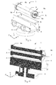
- Figure 1a-1c show one possible embodiment of a calibration device 1 according to the invention for calibration of a laser beam horizontal trueness testing device. It comprises an elongated v-groove bearing block (v-block) 4 as a support body, which in this example is positioned on a levelling base 5, and an elongated laser drum 3 with a longitudinal axis A as a laser housing.
- Figure 1a is a 3D-view where the v-block 4 and the laser drum 3 are drawn separated from each other for overview purposes.
- Figure 1b is a 3D-cross section view along the length of the drum 3 and the v-block 4, sectioned along a zy-plane
- figure 1c is a 2D-cross section view, sectioned along the zx-plane.
- the laser drum 3 is in its intended position for the calibration process according to the invention, lying onto the v-block 4.
- the v-block 4 is holding the laser drum 3.
- the optional levelling base 5 allows levelling the device 1 at setup. The levelling of the v-block 4 does not need to be precise as the levelling plane is determined during the measurement process as described below (see figures 5a-5d ).
- the laser drum 3 is in principle a strung-out hollow cylinder with a laser source 2 in the center of its end 6a, such that the laser beam from the laser source 2 propagates along the inner of the cylinder (y-direction) before leaving the laser drum 3 and at least roughly in direction of the longitudinal axis A.
- the drum 3 is made of a single piece of precision ground, smooth and preferably (surface) hardened material like high speed steel, ceramics or glass.
- materials are chosen with low coefficient of thermal expansion like special ceramics.
- the manufacturing of the laser drum 3 can be done as a single piece in one setup at low to moderate cost.
- the laser drum 3 only requires two rings of the same diameter of limited width that are ground circular.
- both ends 6a, 6b of the drum 3 are fitted with an inner race of a needle bearing 9a, 9b, which is hardened, precision ground and a low cost of the shelve component.
- the drum 3 is resting on to the bearing races inside the v-block 4, wherefore the size of the laser drum 3 and the v-block 4 are matched to each other such that the laser drum 3 rests stable onto the v-block 4 solely by gravity without any connection means.
- a preferable value for the length of the laser drum 3 and accordingly the v-block 4 is about 150mm-200mm. A greater length makes the positioning of the laser drum 3 more stable but results in a more bulky device. In other words, the longer the v-block 4, the lower the accuracy requirements on the components used but the less handy is the apparatus.
- the center of the drum 3 can consist of a simple aluminum pipe. On to each end of the pipe a seat is machined to hold a common deep groove roller bearing. Two roller bearings are pressed on to the pipe. Each roller bearing is specially treated, to prevent the outer race of the roller bearing from rotating. Such a treatment can for instance be simple degreasing of the roller bearing followed by a gluing step where the outer bearing is glued against the inner bearing. Another method of securing the outer race to the inner race could be a mechanical clamping mechanism. Instead of using bearings, pre-ground solid rings are used (for instance the inner or outer races only).
- the alignment and accuracy of the guiding surfaces of the laser drum 3 are machined once more in a final machining step.
- the different manufacturing solutions are tradeoffs between accuracy, availability and cost.
- the in-accuracies introduced by manufacturing tolerances are fixed with the each component. These deviations will not change with thermal cycling wherefore these deviations can be determined ex-factory in a calibration step.
- the v-block 4 is also precision ground, smooth, hardened and an off-the-shelve-part.
- the v-block 4 can be easily ground as a single block in one setup and machined with high accuracy. Since the machining of the v-block 4 is relatively easy, it can be produced at low to moderate cost.
- similar material choices apply: hardened, precision ground and preferably low thermal expansion coefficient.
- the parts (v-block 4, drum 3) need to be made with moderate to high precision. Assuming the drum 3 has a centering tolerance difference of 20 ⁇ m. A thermal expansion coefficient of 20 ⁇ 10-6 results in a 0.4nm centering change per °C. Depending on the length of the drum 3, the thermal change necessary to be noticeable needs to be 70°C or more. This thermal range is well beyond normal office conditions. Using materials with low thermal expansion coefficients virtually eliminates this potential thermal influence even at gross manufacturing error tolerances.
- the v-shape of the block 4 opens a support array S with a defined inserted direction R, where the laser drum 3 can be inserted with its longitudinal axis A parallel to the inserted direction R in two opposing faces.
- the block 4 does not necessarily have to be v-shaped: as an alternative to a v-shaped block 4, multiple other forms are suitable as a supporting part 4 that for the laser drum 3 which provide smooth and stable support of the laser drum 3 in a support array S with a inserted direction D and a minimized contact area between the laser housing 3 and the support body 4 for at least three different positions of the laser housing 3, e.g. a u-shaped block or two adjacent parallel bars/cylinders.
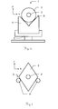
- the laser containing body 3 does not have to be designed as a drum or a cylinder (see also figure 2 ).
- Multiple other forms are possible for the laser housing 3, which allow a self-centering onto the supporting part 4, like a v-block on one side and a ball/sphere on the other side (two lines, one point of contact).
- Fig. 2 shows such an alternative embodiment of a calibration device 1 in a schematic cross section view, where the laser body 3 containing the laser unit 2 is designed as a straight (hollow) prism instead of a cylinder, whereby in the example the cross-section/base area of the prism is formed as a rhombus.
- the rhombus is not (completely) regular but its width is smaller than its length such that the laser body 3 has a preferred up/down-orientation.
- the laser housing 3 is supported by a supporting body 4 designed in essence of two parallel bars and a supporting substruction (the latter not shown).
- the parallel bars have a distance to each other wherefore a support array is in between them, whereby the distance is slightly smaller than the width of the laser body 3 such that the center of gravity of the laser body 3 is as low as possible and the laser body 3 therefore rests stable onto the bars.
- the supporting body 4 is further “reduced” to four balls/spheres or needles situated in one common plane, a pair each at or near each end of the laser body 3.
- the bars, balls etc and their substruction are -likewise the block described above- preferably hardened, precision ground and preferably with a low thermal expansion coefficient to guarantee a stable support for the laser housing 3.
- Figure 3 shows a further embodiment of a calibration device 1, based on the embodiment shown in figures 1a-1c .
- a stopper plate 7a, 7b is mounted at both sides of the v-groove holder 4 .
- Each stopper plate 7a, 7b has machined visual alignment slots 8.
- the laser drum 3 also has an alignment reticle (see figure 4 ). Together with the alignment reticle, the machined alignment slots 8 aid orienting the laser drum 3 in the v-block 4.
- Figure 4 shows one end 6a of a laser drum 3 with an alignment reticle 11.
- the alignment reticle 11 is glued on to the end 6a holding the laser (the side facing the user).
- one line segment 11u of the reticle label 11 of the drum 3 is pointing outwards
- the 180° opposing line segment 11d of the reticle is pointing inwards.
- two 180°-opposing sides of the whole laser drum 3 are marked with lines of different colours or shape (see figures 5a-5d ) to indicate "up” and "down”.
- additional markings are optionally placed. These markings help in characterizing the laser drum 3 in case of gross manufacturing errors.
- the laser drum 3 further comprises adjustment screws 10 for adjusting the laser source 2.
- the laser 2 mounted in the center of the laser drum 3 is adjustable over its horizontal angle as well as its vertical angle (yaw and pitch angles) with the help of the adjustment screws 10.
- the laser diode mounting is fixed to the laser drum 3 with mounting and alignment tolerances as determined by the manufacturing process chosen. As the laser beam horizontal trueness testing device to be verified normally is collimated, it is sufficient to align the translation of optical axis of the laser source 2 only roughly with the mechanical center of the drum 3.
- Figures 5a-5d show an example of calibration method according to the invention for a laser beam horizontal trueness testing device 50, comprising a position sensitive detector 51 and a telescope with an objective.
- the center of the position sensitive detector 51 is arranged on the optical axis of the objective of the laser beam horizontal trueness testing device 50.
- An evaluation unit of the laser beam horizontal trueness testing device 50 is designed for automatically determining an impinging position of the laser beam captured by the detector 51 on the basis of image processing.
- Calibration parameters stored in the evaluation unit represent e.g. the imaging position of the optical axis of the objective on the position sensitive detector 51 and, in particular, a direction in the image which represents an offset direction - brought about hypothetically by a pure horizontality error - of a laser beam impingement position on the detector 51.
- a distance is ascertained which is present in the image captured by the detector 51 between the impinging position and the imaging position in that direction which is assumed as direction or is stored in the calibration parameters and which represents an offset direction - brought about hypothetically by a pure horizontality error - of a laser beam impingement position on the positions sensitive detector 51.
- Said distance - in particular in accordance with a translation factor defined by the objective imaging ratio - can be translated into the laser beam inclination value.
- Figure 5a shows the set-up for the first measurement.
- the laser drum 3 lies onto the v-block 4 pointing into a first face F1 (to the left side in the figure, laser source 2 at the right end of the v-block 4), the v-block 4 levelled only roughly wherefore the horizontal direction of the laser beam L shows possibly a plane error.
- the laser beam horizontal trueness testing device 50 to be calibrated is positioned such, that the laser beam L of the calibration device 1 is imaged on the position sensitive detector (image sensor, provided for example as a CMOS or CCD chip) 51 of the laser beam horizontal trueness testing device 50.
- the position sensitive detector image sensor, provided for example as a CMOS or CCD chip
- a first measurement of a first impinging position P1 of the laser beam L on the position sensitive detector 51 is made i.e. an image position of the laser beam L captured in the image is determined on the basis of image processing.
- Figure 5b shows the set-up for the second measurement.
- the laser drum 3 is still in the first face F1, but has been rotated 180° around the y-axis, such that compared to the set up of figure 5a , the laser drum 3 is lying on its "back". The rotation is done with the help of a marking line 11d indicating "down" (see also figure 4 ).
- a second measurement of a second position P2 of the laser beam L on the sensor 51 is made, which normally is different to the first impinging position P1 due to a cone error of the laser beam L.
- the laser drum 3 is flipped over so that the laser source 2 is in the second opposing face F2, pointing to the other side (180° rotation of the laser drum 3 around the x-axis of the v-block 4) as shown in figure 5c .
- the laser drum 3 in one position pointing to the front of the v-block 4 ( figures 5a and 5b ), and in the other position pointing to the back of the v-block 4 ( figures 5c and 5d ). Accordingly, the laser drum 3 is now lying with its "bottom" side on the v-block 4 again, likewise in figure 5a , which is indicated by the marking line 11u indicating "up".
- the laser beam horizontal trueness testing device 50 is now positioned on the other side of the calibration device 1 such that the laser beam L of the calibration device 1 is imaged on its position sensitive detector 51.
- a third measurement of a third impinging position P3 of the laser beam L on the position sensitive sensor 51 is made.
- the laser drum 3 has less mass compared to the v-block 4 and is repositioned at the same contact position in the v-block 4 when rotated around the x-axis. This results in no change of the center point of gravity of the setup when flipping over. There is no play between the v-block 4 and laser drum 3. The accuracy of this measurement principle therefore is determined by the manufacturing accuracy of the v-block 4 and the laser drum 3.
- Figure 5d shows the fourth and possibly final set-up.
- the laser drum 3 is still in the second face F2, but has been rotated 180° around the y-axis, such that compared to the set up of figure 5c , the laser drum 3 is lying on its "back".
- a fourth measurement of a fourth impinging position P4 of the laser beam L on the position sensitive detector 51 is made which again differs form the third position P3 due to cone error. Due to the plane error caused by the non-exact levelling the third and fourth impinging positions P3, P4 are not reverse to the first and second impinging positions P1, P2 but show an offset, dependent on the quantity of the deviation from perfect level.
- the position of the v-block 4 remains unchanged during the measurement procedure. It is further to be noted, that the position of the longitudinal axis A in all four positions of the laser housing 3 is equal, what is achieved by the design of the calibration device 1 according to the invention.
- the rotation of the laser drum 3 around the y-axis of the v-block 4 ( figures 5a to 5b and 5c to 5d ) is done in order to determine the cone angles resp. eliminate the cone errors of the laser source 2 resp. its laser beam L.
- Cone error is misalignment of the laser beam L in radial direction from the intended laser beam orientation.
- an ellipse on to the measurement results at multiple (at least three) non-opposing orientations of the laser drum 3 is fitted.
- the cone error of the laser source 2 in the laser drum 3 can be adjusted in both horizontal (yaw) and vertical angle (pitch). By adjusting both angles can be controlled to be substantially less than for example 30 seconds of arc.
- the rotation of the laser drum 3 around the x-axis of the v-bock 4 (change from first face F1 to second face F2, figure 5b to 5c ) is done in order to determine the laser plane resp. laser line of the laser beam L resp. in order to even out the non-exact levelling of the laser plane resp. laser line resp. the non-exact levelling of the whole calibration device 1 (see figure 1 ).
- the laser drum 3 by rotating the laser drum 3 around the length axis of the v-block (y-axis), it is possible to align the laser source 2 mounted in the center of the laser drum 3 in such a way that the cone errors in horizontal direction (rotation around z-axis) and vertical direction (rotation around x-axis) are cancelled.
- the level point, i.e. the impinging position on the positions sensitive detector 51 for an impinging laser beam of true horizontality, of the laser beam horizontal trueness testing device 50 is the center of the four image sensor positions P1-P4 measured. Therefore, the real center position of the optical axis projected to the position sensitive detector 51 of the laser beam horizontal trueness testing device 50 is obtained by averaging all four measurement results P1-P4. Thus, the calibration of the laser beam horizontal trueness testing device 50 is finalized in essence and the level point is newly set by the newly determined calibration parameters.
- the averaging and calibration is preferably done by a control unit (not shown) of the laser beam horizontal trueness testing device 50, wherefore in control unit is implemented a program for a calibration verification functionality for a laser beam horizontal trueness testing device 50.
- the method respectively calibration functionality comprises multiple readings to improve the standard deviation of the resulting center position resp. level point. Taking multiple readings at multiple orientations of the drum 3, each 180° opposite further improves the result. If the determined cone error is larger than 10" it can be reduced using the adjustment screws at the laser source 2.
- the laser source 2 is designed as a line laser source, it allows in addition measurement of the rotation angle over which the laser drum 3 was rotated by measurement of the angle of the projected line to the orientation of the position sensitive detector 51. By measuring the difference of the line angles between the two cone error measurements, the actual rotation angle can be determined.
- the cone angle in inclination direction is measured as the orthogonal distance between the sensor center and the projected laser line.
- the measurement method uses the property of the optomechanical tilt adjustment device (compensator) in laser beam horizontal trueness testing device 50.
- the compensator ensures that the optical line of sight of the laser beam horizontal trueness testing device 50 is always leveled (setting accuracy typically ⁇ 0.3 seconds of arc and linearity error of typically ⁇ 1 second of arc"/10minutes of tilt), providing certainty of the optical line of sight.
- the level of the laser beam horizontal trueness testing device 50 can be adjusted within the working range of the compensator.
- the accuracy of the compensator allows moving the laser beam horizontal trueness testing device 50 from front to back of the v-block 4 without significant impact on measurement resp. calibration accuracy.
- the laser plane resp. laser line of the v-block 4 setup can be accurately determined.
- the laser drum 3 is to be rotated around the x-axis to point in front / rear direction.
- the laser beam horizontal trueness testing device 50 When moving the laser beam horizontal trueness testing device 50 from front to back of the v-block 4 ( figures 5b to 5c ), the laser beam horizontal trueness testing device 50 needs to be positioned in the same horizontal angular alignment as where it was in the front. This is roughly achieved using the side drive of the laser beam horizontal trueness testing device 50.
- the center of position sensitive detector 51 of the current calibration parameters is used. The deviation of the current position in the front setting from the detector center is determined. Combined with the current orientation parameter of the position sensitive detector 51, the offset of the new position when the laser beam horizontal trueness testing device 50 has been moved to the back of the v-block 4 to the correct position is calculated and corrected for.
- the side drive of the laser beam horizontal trueness testing device 50 allows its azimuthal rotation. This is used in a further development of the calibration method: using the known laser plane and cone angles after the initial measurements, the rotation of the position sensitive detector 51 around the y-axis is determined by azimuthal rotation of the laser beam horizontal trueness testing device 50 over a known angle. The azimuthal angle over which the horizontal trueness testing device 50 was rotated is determined by the horizontal trueness testing device 50 itself. With known azimuthal rotation angle and known plane and cone errors, the rotation of the position sensitive detector 51 around the y-axis resp. a deviation from its ideal rotational position is determined.
Landscapes
- Engineering & Computer Science (AREA)
- Physics & Mathematics (AREA)
- General Physics & Mathematics (AREA)
- Radar, Positioning & Navigation (AREA)
- Remote Sensing (AREA)
- Manufacturing & Machinery (AREA)
- Length Measuring Devices By Optical Means (AREA)
Priority Applications (3)
| Application Number | Priority Date | Filing Date | Title |
|---|---|---|---|
| EP15177314.0A EP3118577B1 (fr) | 2015-07-17 | 2015-07-17 | Dispositif et procédé d'étalonnage pour dispositif de test de l'exactitude d'un faisceau laser |
| CN201610561705.XA CN106352892B (zh) | 2015-07-17 | 2016-07-15 | 用于激光束水平精度测试装置的校准装置和校准方法 |
| US15/212,212 US9964417B2 (en) | 2015-07-17 | 2016-07-16 | Calibration device and calibration method for a laser beam horizontal trueness testing device |
Applications Claiming Priority (1)
| Application Number | Priority Date | Filing Date | Title |
|---|---|---|---|
| EP15177314.0A EP3118577B1 (fr) | 2015-07-17 | 2015-07-17 | Dispositif et procédé d'étalonnage pour dispositif de test de l'exactitude d'un faisceau laser |
Publications (2)
| Publication Number | Publication Date |
|---|---|
| EP3118577A1 true EP3118577A1 (fr) | 2017-01-18 |
| EP3118577B1 EP3118577B1 (fr) | 2019-06-26 |
Family
ID=53682557
Family Applications (1)
| Application Number | Title | Priority Date | Filing Date |
|---|---|---|---|
| EP15177314.0A Active EP3118577B1 (fr) | 2015-07-17 | 2015-07-17 | Dispositif et procédé d'étalonnage pour dispositif de test de l'exactitude d'un faisceau laser |
Country Status (3)
| Country | Link |
|---|---|
| US (1) | US9964417B2 (fr) |
| EP (1) | EP3118577B1 (fr) |
| CN (1) | CN106352892B (fr) |
Cited By (2)
| Publication number | Priority date | Publication date | Assignee | Title |
|---|---|---|---|---|
| CN108489516A (zh) * | 2018-06-26 | 2018-09-04 | 郑州市质量技术监督检验测试中心 | 一种图像式激光标线仪综合校准装置及校准方法 |
| CN114088345A (zh) * | 2021-11-23 | 2022-02-25 | 山东省肿瘤医院 | 基于准直器的定位激光灯质控装置及其使用方法 |
Families Citing this family (16)
| Publication number | Priority date | Publication date | Assignee | Title |
|---|---|---|---|---|
| EP3118577B1 (fr) * | 2015-07-17 | 2019-06-26 | Leica Geosystems AG | Dispositif et procédé d'étalonnage pour dispositif de test de l'exactitude d'un faisceau laser |
| CN107144934B (zh) * | 2017-06-12 | 2022-12-27 | 中国科学院西安光学精密机械研究所 | 光轴指示调节机构及其指示调节方法 |
| CN107449446B (zh) * | 2017-08-30 | 2023-04-07 | 东莞欧达电子有限公司 | 一种激光准直设备的坡度测量系统及其测量方法 |
| CN108151767A (zh) * | 2018-02-01 | 2018-06-12 | 广东开放大学(广东理工职业学院) | 一种校准用旋转激光束投射装置及其校准方法 |
| CN108490574B (zh) * | 2018-05-11 | 2023-05-26 | 中国科学院西安光学精密机械研究所 | 一种光轴五维指示调节机构及调节方法 |
| CN109269482B (zh) * | 2018-08-09 | 2021-11-23 | 中山市聚云软件科技有限公司 | 一种桥梁防碰撞激光水平检测方法 |
| CN111982078B (zh) * | 2019-05-21 | 2022-03-29 | 中国石油天然气股份有限公司 | 钻井平台稳定性精密激光监测装置及激光漂移校准方法 |
| CN110702040A (zh) * | 2019-09-02 | 2020-01-17 | 晶澳(邢台)太阳能有限公司 | 一种多角度平行校准装置 |
| CN110763162B (zh) * | 2019-10-17 | 2024-04-02 | 四川大学 | 一种超精密线激光转角感测方法 |
| CN110794385B (zh) * | 2019-10-18 | 2021-07-13 | 北京空间机电研究所 | 一种激光器零重力指向的评估方法及系统 |
| CN110769204B (zh) * | 2019-11-13 | 2021-04-30 | 秒针信息技术有限公司 | 图像采集的管理方法和装置 |
| DE102020204536A1 (de) | 2020-04-08 | 2021-10-14 | Prüftechnik Dieter Busch GmbH | Laservorrichtung und Verfahren zum Einstellen einer Laservorrichtung |
| CN111451634A (zh) * | 2020-04-30 | 2020-07-28 | 中车青岛四方机车车辆股份有限公司 | 激光焊接设备校准方法 |
| CN112611396B (zh) * | 2020-12-31 | 2024-05-03 | 上海诺司纬光电仪器有限公司 | 用于校准激光扫平仪的方法 |
| CN113776510B (zh) * | 2021-11-15 | 2022-02-22 | 枣庄高新建设集团有限公司 | 一种建筑工程造价现场测绘装置 |
| CN116625652B (zh) * | 2023-07-21 | 2023-10-10 | 武汉斯优光电技术有限公司 | 一种激光器成品检测设备 |
Citations (4)
| Publication number | Priority date | Publication date | Assignee | Title |
|---|---|---|---|---|
| US6178649B1 (en) * | 1998-01-16 | 2001-01-30 | Chyi-Yiing Wu | Optical calibrating apparatus for emitting datum laser line |
| US6539638B1 (en) * | 2000-04-27 | 2003-04-01 | Victor Pelletier | Line projecting device |
| DE102007039343A1 (de) * | 2007-08-21 | 2009-02-26 | Robert Bosch Gmbh | Laservorrichtung und System mit einer Laservorrichtung |
| EP2741049A1 (fr) | 2012-12-05 | 2014-06-11 | Leica Geosystems AG | Dispositif de vérification de la fidélité de l'horizontalité du faisceau laser et procédé correspondant |
Family Cites Families (12)
| Publication number | Priority date | Publication date | Assignee | Title |
|---|---|---|---|---|
| GB0215557D0 (en) * | 2002-07-05 | 2002-08-14 | Renishaw Plc | Laser calibration apparatus |
| EP1503175A1 (fr) * | 2003-07-28 | 2005-02-02 | Leica Geosystems AG | Dispositif et procédé de calibrage de l'alignement d'un dispositif à tester |
| TW200530629A (en) * | 2004-02-13 | 2005-09-16 | Black & Decker Inc | Laser calibration apparatus and method |
| WO2006125280A1 (fr) * | 2005-05-27 | 2006-11-30 | Opto Global Holdings Pty Ltd | Systeme et procede de calibrage de laser |
| EP2199739A1 (fr) * | 2008-12-17 | 2010-06-23 | Leica Geosystems AG | Récepteur laser pour la détection d'une position relative |
| GB2517624B (en) * | 2012-05-16 | 2016-08-10 | Faro Tech Inc | An apparatus and method to compensate bearing runout in laser tracker |
| EP2687866A1 (fr) * | 2012-07-19 | 2014-01-22 | Leica Geosystems AG | Appareil de suivi laser avec unité de calibrage pour calibrage automatique |
| EP2746807A1 (fr) * | 2012-12-20 | 2014-06-25 | Leica Geosystems AG | Appareil de suivi laser à calibrage automatique et procédé de calibrage automatique |
| EP2781879B1 (fr) * | 2013-03-19 | 2015-09-30 | Leica Geosystems AG | Système de laser de construction constitué d'un laser rotatif et d'un récepteur laser, doté d'une fonctionnalité de détermination automatique de la direction du récepteur laser |
| EP2781880B1 (fr) * | 2013-03-19 | 2019-01-16 | Leica Geosystems AG | Système de laser de construction comportant une fonctionnalité de recalibrage s'exécutant de manière au moins partiellement automatique pour une fonctionnalité de mise à l'horizontale du rayon |
| CN203837692U (zh) * | 2014-04-02 | 2014-09-17 | 温州大学 | 一种具有自校准功能的激光测高仪 |
| EP3118577B1 (fr) * | 2015-07-17 | 2019-06-26 | Leica Geosystems AG | Dispositif et procédé d'étalonnage pour dispositif de test de l'exactitude d'un faisceau laser |
-
2015
- 2015-07-17 EP EP15177314.0A patent/EP3118577B1/fr active Active
-
2016
- 2016-07-15 CN CN201610561705.XA patent/CN106352892B/zh active Active
- 2016-07-16 US US15/212,212 patent/US9964417B2/en active Active
Patent Citations (4)
| Publication number | Priority date | Publication date | Assignee | Title |
|---|---|---|---|---|
| US6178649B1 (en) * | 1998-01-16 | 2001-01-30 | Chyi-Yiing Wu | Optical calibrating apparatus for emitting datum laser line |
| US6539638B1 (en) * | 2000-04-27 | 2003-04-01 | Victor Pelletier | Line projecting device |
| DE102007039343A1 (de) * | 2007-08-21 | 2009-02-26 | Robert Bosch Gmbh | Laservorrichtung und System mit einer Laservorrichtung |
| EP2741049A1 (fr) | 2012-12-05 | 2014-06-11 | Leica Geosystems AG | Dispositif de vérification de la fidélité de l'horizontalité du faisceau laser et procédé correspondant |
Non-Patent Citations (1)
| Title |
|---|
| THORLABS: "Cylindrical Kinematic V-Clamp", LARGE CLAMPING ARM ROTATES 10° HENE LASERS, 2007, Thorlabs catalog V19, pages 70 - 140, XP055242857, Retrieved from the Internet <URL:http://www.thorlabs.com/catalogPages/199.pdf> [retrieved on 20160119] * |
Cited By (3)
| Publication number | Priority date | Publication date | Assignee | Title |
|---|---|---|---|---|
| CN108489516A (zh) * | 2018-06-26 | 2018-09-04 | 郑州市质量技术监督检验测试中心 | 一种图像式激光标线仪综合校准装置及校准方法 |
| CN108489516B (zh) * | 2018-06-26 | 2023-08-11 | 郑州市质量技术监督检验测试中心 | 一种图像式激光标线仪综合校准装置及校准方法 |
| CN114088345A (zh) * | 2021-11-23 | 2022-02-25 | 山东省肿瘤医院 | 基于准直器的定位激光灯质控装置及其使用方法 |
Also Published As
| Publication number | Publication date |
|---|---|
| EP3118577B1 (fr) | 2019-06-26 |
| US20170016743A1 (en) | 2017-01-19 |
| US9964417B2 (en) | 2018-05-08 |
| CN106352892B (zh) | 2019-09-24 |
| CN106352892A (zh) | 2017-01-25 |
Similar Documents
| Publication | Publication Date | Title |
|---|---|---|
| EP3118577B1 (fr) | Dispositif et procédé d'étalonnage pour dispositif de test de l'exactitude d'un faisceau laser | |
| JP4417958B2 (ja) | 高精度試験体の角度依存アライメントの検査または校正装置 | |
| CN105352436B (zh) | 激光跟踪器、测量远程点的坐标的方法和坐标测量系统 | |
| US6195615B1 (en) | Method of mutually aligning bodies and position-measuring sensor therefor | |
| US9644960B2 (en) | Laser beam horizontal trueness testing device and corresponding method | |
| US20180356223A1 (en) | Method for Checking and/or Calibrating a Horizontal Axis of a Rotating Laser | |
| KR19980703264A (ko) | 계측구-반사기 | |
| US7665218B1 (en) | Azimuth measuring apparatus and method | |
| US6658750B2 (en) | Method and measurement device for measurement of a two-wheeled vehicle frame | |
| JP2000028362A (ja) | 測量機の求心位置測定装置及び測量機 | |
| RU2419766C1 (ru) | Стенд для поверки и калибровки цифровых нивелиров и штрихкодовых реек | |
| CN105716593A (zh) | 一种用于光电侦察系统定向定位精度测试的测试装置及测试方法 | |
| US9194698B2 (en) | Geodetic device and a method for determining a characteristic of the device | |
| JP5030699B2 (ja) | 厚さ計測装置の調整方法及びその装置 | |
| CN103090821A (zh) | 在三个轴的平面内确定通过两个万向节及第三轴相连的两个轴的方位的方法 | |
| JP2009281768A (ja) | 測定装置 | |
| CN103090822A (zh) | 确定通过两个万向节及带有转动接头的第三轴连接的两个轴的方位的装置和方法 | |
| JP2009098092A (ja) | 相対高さ検出装置 | |
| JP2010038892A (ja) | 長尺円筒部材の真直度計測治具とその計測方法 | |
| KR970003085Y1 (ko) | 각도측정기 | |
| JP2019207146A (ja) | 測量機器点検システム、測量機器点検システムを用いた機器の調整方法 | |
| RU2767804C1 (ru) | Оптический стенд | |
| KR102402575B1 (ko) | 센서 검사 장치 | |
| US11092436B1 (en) | Leveling instrument with multiple sensitivities | |
| US10508905B2 (en) | Device and method for measuring cavities and use of the device for determining roller alignments |
Legal Events
| Date | Code | Title | Description |
|---|---|---|---|
| PUAI | Public reference made under article 153(3) epc to a published international application that has entered the european phase |
Free format text: ORIGINAL CODE: 0009012 |
|
| STAA | Information on the status of an ep patent application or granted ep patent |
Free format text: STATUS: THE APPLICATION HAS BEEN PUBLISHED |
|
| AK | Designated contracting states |
Kind code of ref document: A1 Designated state(s): AL AT BE BG CH CY CZ DE DK EE ES FI FR GB GR HR HU IE IS IT LI LT LU LV MC MK MT NL NO PL PT RO RS SE SI SK SM TR |
|
| AX | Request for extension of the european patent |
Extension state: BA ME |
|
| STAA | Information on the status of an ep patent application or granted ep patent |
Free format text: STATUS: REQUEST FOR EXAMINATION WAS MADE |
|
| 17P | Request for examination filed |
Effective date: 20170713 |
|
| RBV | Designated contracting states (corrected) |
Designated state(s): AL AT BE BG CH CY CZ DE DK EE ES FI FR GB GR HR HU IE IS IT LI LT LU LV MC MK MT NL NO PL PT RO RS SE SI SK SM TR |
|
| RIN1 | Information on inventor provided before grant (corrected) |
Inventor name: DUMOULIN, CHARLES LEOPOLD ELISABETH Inventor name: BRODER, KATHERINE |
|
| GRAP | Despatch of communication of intention to grant a patent |
Free format text: ORIGINAL CODE: EPIDOSNIGR1 |
|
| STAA | Information on the status of an ep patent application or granted ep patent |
Free format text: STATUS: GRANT OF PATENT IS INTENDED |
|
| INTG | Intention to grant announced |
Effective date: 20190307 |
|
| RIN1 | Information on inventor provided before grant (corrected) |
Inventor name: DUMOULIN, CHARLES LEOPOLD ELISABETH Inventor name: BRODER, KATHERINE |
|
| GRAS | Grant fee paid |
Free format text: ORIGINAL CODE: EPIDOSNIGR3 |
|
| GRAA | (expected) grant |
Free format text: ORIGINAL CODE: 0009210 |
|
| STAA | Information on the status of an ep patent application or granted ep patent |
Free format text: STATUS: THE PATENT HAS BEEN GRANTED |
|
| AK | Designated contracting states |
Kind code of ref document: B1 Designated state(s): AL AT BE BG CH CY CZ DE DK EE ES FI FR GB GR HR HU IE IS IT LI LT LU LV MC MK MT NL NO PL PT RO RS SE SI SK SM TR |
|
| REG | Reference to a national code |
Ref country code: GB Ref legal event code: FG4D |
|
| REG | Reference to a national code |
Ref country code: CH Ref legal event code: EP |
|
| REG | Reference to a national code |
Ref country code: AT Ref legal event code: REF Ref document number: 1148807 Country of ref document: AT Kind code of ref document: T Effective date: 20190715 |
|
| REG | Reference to a national code |
Ref country code: DE Ref legal event code: R096 Ref document number: 602015032589 Country of ref document: DE |
|
| REG | Reference to a national code |
Ref country code: IE Ref legal event code: FG4D |
|
| REG | Reference to a national code |
Ref country code: NL Ref legal event code: MP Effective date: 20190626 |
|
| PG25 | Lapsed in a contracting state [announced via postgrant information from national office to epo] |
Ref country code: AL Free format text: LAPSE BECAUSE OF FAILURE TO SUBMIT A TRANSLATION OF THE DESCRIPTION OR TO PAY THE FEE WITHIN THE PRESCRIBED TIME-LIMIT Effective date: 20190626 Ref country code: SE Free format text: LAPSE BECAUSE OF FAILURE TO SUBMIT A TRANSLATION OF THE DESCRIPTION OR TO PAY THE FEE WITHIN THE PRESCRIBED TIME-LIMIT Effective date: 20190626 Ref country code: LT Free format text: LAPSE BECAUSE OF FAILURE TO SUBMIT A TRANSLATION OF THE DESCRIPTION OR TO PAY THE FEE WITHIN THE PRESCRIBED TIME-LIMIT Effective date: 20190626 Ref country code: HR Free format text: LAPSE BECAUSE OF FAILURE TO SUBMIT A TRANSLATION OF THE DESCRIPTION OR TO PAY THE FEE WITHIN THE PRESCRIBED TIME-LIMIT Effective date: 20190626 Ref country code: FI Free format text: LAPSE BECAUSE OF FAILURE TO SUBMIT A TRANSLATION OF THE DESCRIPTION OR TO PAY THE FEE WITHIN THE PRESCRIBED TIME-LIMIT Effective date: 20190626 Ref country code: NO Free format text: LAPSE BECAUSE OF FAILURE TO SUBMIT A TRANSLATION OF THE DESCRIPTION OR TO PAY THE FEE WITHIN THE PRESCRIBED TIME-LIMIT Effective date: 20190926 |
|
| REG | Reference to a national code |
Ref country code: LT Ref legal event code: MG4D |
|
| PG25 | Lapsed in a contracting state [announced via postgrant information from national office to epo] |
Ref country code: BG Free format text: LAPSE BECAUSE OF FAILURE TO SUBMIT A TRANSLATION OF THE DESCRIPTION OR TO PAY THE FEE WITHIN THE PRESCRIBED TIME-LIMIT Effective date: 20190926 Ref country code: RS Free format text: LAPSE BECAUSE OF FAILURE TO SUBMIT A TRANSLATION OF THE DESCRIPTION OR TO PAY THE FEE WITHIN THE PRESCRIBED TIME-LIMIT Effective date: 20190626 Ref country code: GR Free format text: LAPSE BECAUSE OF FAILURE TO SUBMIT A TRANSLATION OF THE DESCRIPTION OR TO PAY THE FEE WITHIN THE PRESCRIBED TIME-LIMIT Effective date: 20190927 Ref country code: LV Free format text: LAPSE BECAUSE OF FAILURE TO SUBMIT A TRANSLATION OF THE DESCRIPTION OR TO PAY THE FEE WITHIN THE PRESCRIBED TIME-LIMIT Effective date: 20190626 |
|
| REG | Reference to a national code |
Ref country code: AT Ref legal event code: MK05 Ref document number: 1148807 Country of ref document: AT Kind code of ref document: T Effective date: 20190626 |
|
| PG25 | Lapsed in a contracting state [announced via postgrant information from national office to epo] |
Ref country code: NL Free format text: LAPSE BECAUSE OF FAILURE TO SUBMIT A TRANSLATION OF THE DESCRIPTION OR TO PAY THE FEE WITHIN THE PRESCRIBED TIME-LIMIT Effective date: 20190626 Ref country code: PT Free format text: LAPSE BECAUSE OF FAILURE TO SUBMIT A TRANSLATION OF THE DESCRIPTION OR TO PAY THE FEE WITHIN THE PRESCRIBED TIME-LIMIT Effective date: 20191028 Ref country code: RO Free format text: LAPSE BECAUSE OF FAILURE TO SUBMIT A TRANSLATION OF THE DESCRIPTION OR TO PAY THE FEE WITHIN THE PRESCRIBED TIME-LIMIT Effective date: 20190626 Ref country code: SK Free format text: LAPSE BECAUSE OF FAILURE TO SUBMIT A TRANSLATION OF THE DESCRIPTION OR TO PAY THE FEE WITHIN THE PRESCRIBED TIME-LIMIT Effective date: 20190626 Ref country code: CZ Free format text: LAPSE BECAUSE OF FAILURE TO SUBMIT A TRANSLATION OF THE DESCRIPTION OR TO PAY THE FEE WITHIN THE PRESCRIBED TIME-LIMIT Effective date: 20190626 Ref country code: EE Free format text: LAPSE BECAUSE OF FAILURE TO SUBMIT A TRANSLATION OF THE DESCRIPTION OR TO PAY THE FEE WITHIN THE PRESCRIBED TIME-LIMIT Effective date: 20190626 Ref country code: AT Free format text: LAPSE BECAUSE OF FAILURE TO SUBMIT A TRANSLATION OF THE DESCRIPTION OR TO PAY THE FEE WITHIN THE PRESCRIBED TIME-LIMIT Effective date: 20190626 |
|
| PG25 | Lapsed in a contracting state [announced via postgrant information from national office to epo] |
Ref country code: ES Free format text: LAPSE BECAUSE OF FAILURE TO SUBMIT A TRANSLATION OF THE DESCRIPTION OR TO PAY THE FEE WITHIN THE PRESCRIBED TIME-LIMIT Effective date: 20190626 Ref country code: IT Free format text: LAPSE BECAUSE OF FAILURE TO SUBMIT A TRANSLATION OF THE DESCRIPTION OR TO PAY THE FEE WITHIN THE PRESCRIBED TIME-LIMIT Effective date: 20190626 Ref country code: SM Free format text: LAPSE BECAUSE OF FAILURE TO SUBMIT A TRANSLATION OF THE DESCRIPTION OR TO PAY THE FEE WITHIN THE PRESCRIBED TIME-LIMIT Effective date: 20190626 Ref country code: IS Free format text: LAPSE BECAUSE OF FAILURE TO SUBMIT A TRANSLATION OF THE DESCRIPTION OR TO PAY THE FEE WITHIN THE PRESCRIBED TIME-LIMIT Effective date: 20191026 |
|
| REG | Reference to a national code |
Ref country code: CH Ref legal event code: PL |
|
| PG25 | Lapsed in a contracting state [announced via postgrant information from national office to epo] |
Ref country code: MC Free format text: LAPSE BECAUSE OF FAILURE TO SUBMIT A TRANSLATION OF THE DESCRIPTION OR TO PAY THE FEE WITHIN THE PRESCRIBED TIME-LIMIT Effective date: 20190626 Ref country code: TR Free format text: LAPSE BECAUSE OF FAILURE TO SUBMIT A TRANSLATION OF THE DESCRIPTION OR TO PAY THE FEE WITHIN THE PRESCRIBED TIME-LIMIT Effective date: 20190626 |
|
| REG | Reference to a national code |
Ref country code: BE Ref legal event code: MM Effective date: 20190731 |
|
| PG25 | Lapsed in a contracting state [announced via postgrant information from national office to epo] |
Ref country code: PL Free format text: LAPSE BECAUSE OF FAILURE TO SUBMIT A TRANSLATION OF THE DESCRIPTION OR TO PAY THE FEE WITHIN THE PRESCRIBED TIME-LIMIT Effective date: 20190626 Ref country code: DK Free format text: LAPSE BECAUSE OF FAILURE TO SUBMIT A TRANSLATION OF THE DESCRIPTION OR TO PAY THE FEE WITHIN THE PRESCRIBED TIME-LIMIT Effective date: 20190626 |
|
| PG25 | Lapsed in a contracting state [announced via postgrant information from national office to epo] |
Ref country code: LU Free format text: LAPSE BECAUSE OF NON-PAYMENT OF DUE FEES Effective date: 20190717 Ref country code: IS Free format text: LAPSE BECAUSE OF FAILURE TO SUBMIT A TRANSLATION OF THE DESCRIPTION OR TO PAY THE FEE WITHIN THE PRESCRIBED TIME-LIMIT Effective date: 20200224 Ref country code: LI Free format text: LAPSE BECAUSE OF NON-PAYMENT OF DUE FEES Effective date: 20190731 Ref country code: CH Free format text: LAPSE BECAUSE OF NON-PAYMENT OF DUE FEES Effective date: 20190731 Ref country code: BE Free format text: LAPSE BECAUSE OF NON-PAYMENT OF DUE FEES Effective date: 20190731 |
|
| REG | Reference to a national code |
Ref country code: DE Ref legal event code: R097 Ref document number: 602015032589 Country of ref document: DE |
|
| PLBE | No opposition filed within time limit |
Free format text: ORIGINAL CODE: 0009261 |
|
| STAA | Information on the status of an ep patent application or granted ep patent |
Free format text: STATUS: NO OPPOSITION FILED WITHIN TIME LIMIT |
|
| PG2D | Information on lapse in contracting state deleted |
Ref country code: IS |
|
| PG25 | Lapsed in a contracting state [announced via postgrant information from national office to epo] |
Ref country code: IE Free format text: LAPSE BECAUSE OF NON-PAYMENT OF DUE FEES Effective date: 20190717 Ref country code: FR Free format text: LAPSE BECAUSE OF NON-PAYMENT OF DUE FEES Effective date: 20190826 |
|
| 26N | No opposition filed |
Effective date: 20200603 |
|
| PG25 | Lapsed in a contracting state [announced via postgrant information from national office to epo] |
Ref country code: SI Free format text: LAPSE BECAUSE OF FAILURE TO SUBMIT A TRANSLATION OF THE DESCRIPTION OR TO PAY THE FEE WITHIN THE PRESCRIBED TIME-LIMIT Effective date: 20190626 |
|
| PG25 | Lapsed in a contracting state [announced via postgrant information from national office to epo] |
Ref country code: CY Free format text: LAPSE BECAUSE OF FAILURE TO SUBMIT A TRANSLATION OF THE DESCRIPTION OR TO PAY THE FEE WITHIN THE PRESCRIBED TIME-LIMIT Effective date: 20190626 |
|
| PG25 | Lapsed in a contracting state [announced via postgrant information from national office to epo] |
Ref country code: MT Free format text: LAPSE BECAUSE OF FAILURE TO SUBMIT A TRANSLATION OF THE DESCRIPTION OR TO PAY THE FEE WITHIN THE PRESCRIBED TIME-LIMIT Effective date: 20190626 Ref country code: HU Free format text: LAPSE BECAUSE OF FAILURE TO SUBMIT A TRANSLATION OF THE DESCRIPTION OR TO PAY THE FEE WITHIN THE PRESCRIBED TIME-LIMIT; INVALID AB INITIO Effective date: 20150717 |
|
| PG25 | Lapsed in a contracting state [announced via postgrant information from national office to epo] |
Ref country code: MK Free format text: LAPSE BECAUSE OF FAILURE TO SUBMIT A TRANSLATION OF THE DESCRIPTION OR TO PAY THE FEE WITHIN THE PRESCRIBED TIME-LIMIT Effective date: 20190626 |
|
| PGFP | Annual fee paid to national office [announced via postgrant information from national office to epo] |
Ref country code: GB Payment date: 20230721 Year of fee payment: 9 |
|
| PGFP | Annual fee paid to national office [announced via postgrant information from national office to epo] |
Ref country code: DE Payment date: 20230719 Year of fee payment: 9 |