EP3115682A1 - Lichtleitende säule und fahrzeuglampe damit - Google Patents
Lichtleitende säule und fahrzeuglampe damit Download PDFInfo
- Publication number
- EP3115682A1 EP3115682A1 EP16176111.9A EP16176111A EP3115682A1 EP 3115682 A1 EP3115682 A1 EP 3115682A1 EP 16176111 A EP16176111 A EP 16176111A EP 3115682 A1 EP3115682 A1 EP 3115682A1
- Authority
- EP
- European Patent Office
- Prior art keywords
- light
- vehicle lamp
- guiding pillar
- major structure
- guiding
- Prior art date
- Legal status (The legal status is an assumption and is not a legal conclusion. Google has not performed a legal analysis and makes no representation as to the accuracy of the status listed.)
- Withdrawn
Links
Images


Classifications
-
- F—MECHANICAL ENGINEERING; LIGHTING; HEATING; WEAPONS; BLASTING
- F21—LIGHTING
- F21S—NON-PORTABLE LIGHTING DEVICES; SYSTEMS THEREOF; VEHICLE LIGHTING DEVICES SPECIALLY ADAPTED FOR VEHICLE EXTERIORS
- F21S41/00—Illuminating devices specially adapted for vehicle exteriors, e.g. headlamps
- F21S41/20—Illuminating devices specially adapted for vehicle exteriors, e.g. headlamps characterised by refractors, transparent cover plates, light guides or filters
- F21S41/24—Light guides
-
- F—MECHANICAL ENGINEERING; LIGHTING; HEATING; WEAPONS; BLASTING
- F21—LIGHTING
- F21S—NON-PORTABLE LIGHTING DEVICES; SYSTEMS THEREOF; VEHICLE LIGHTING DEVICES SPECIALLY ADAPTED FOR VEHICLE EXTERIORS
- F21S45/00—Arrangements within vehicle lighting devices specially adapted for vehicle exteriors, for purposes other than emission or distribution of light
- F21S45/40—Cooling of lighting devices
- F21S45/47—Passive cooling, e.g. using fins, thermal conductive elements or openings
-
- B—PERFORMING OPERATIONS; TRANSPORTING
- B60—VEHICLES IN GENERAL
- B60Q—ARRANGEMENT OF SIGNALLING OR LIGHTING DEVICES, THE MOUNTING OR SUPPORTING THEREOF OR CIRCUITS THEREFOR, FOR VEHICLES IN GENERAL
- B60Q1/00—Arrangement of optical signalling or lighting devices, the mounting or supporting thereof or circuits therefor
- B60Q1/26—Arrangement of optical signalling or lighting devices, the mounting or supporting thereof or circuits therefor the devices being primarily intended to indicate the vehicle, or parts thereof, or to give signals, to other traffic
-
- F—MECHANICAL ENGINEERING; LIGHTING; HEATING; WEAPONS; BLASTING
- F21—LIGHTING
- F21S—NON-PORTABLE LIGHTING DEVICES; SYSTEMS THEREOF; VEHICLE LIGHTING DEVICES SPECIALLY ADAPTED FOR VEHICLE EXTERIORS
- F21S41/00—Illuminating devices specially adapted for vehicle exteriors, e.g. headlamps
- F21S41/10—Illuminating devices specially adapted for vehicle exteriors, e.g. headlamps characterised by the light source
- F21S41/14—Illuminating devices specially adapted for vehicle exteriors, e.g. headlamps characterised by the light source characterised by the type of light source
- F21S41/141—Light emitting diodes [LED]
- F21S41/143—Light emitting diodes [LED] the main emission direction of the LED being parallel to the optical axis of the illuminating device
-
- F—MECHANICAL ENGINEERING; LIGHTING; HEATING; WEAPONS; BLASTING
- F21—LIGHTING
- F21S—NON-PORTABLE LIGHTING DEVICES; SYSTEMS THEREOF; VEHICLE LIGHTING DEVICES SPECIALLY ADAPTED FOR VEHICLE EXTERIORS
- F21S41/00—Illuminating devices specially adapted for vehicle exteriors, e.g. headlamps
- F21S41/20—Illuminating devices specially adapted for vehicle exteriors, e.g. headlamps characterised by refractors, transparent cover plates, light guides or filters
- F21S41/25—Projection lenses
- F21S41/255—Lenses with a front view of circular or truncated circular outline
-
- F—MECHANICAL ENGINEERING; LIGHTING; HEATING; WEAPONS; BLASTING
- F21—LIGHTING
- F21S—NON-PORTABLE LIGHTING DEVICES; SYSTEMS THEREOF; VEHICLE LIGHTING DEVICES SPECIALLY ADAPTED FOR VEHICLE EXTERIORS
- F21S41/00—Illuminating devices specially adapted for vehicle exteriors, e.g. headlamps
- F21S41/30—Illuminating devices specially adapted for vehicle exteriors, e.g. headlamps characterised by reflectors
- F21S41/32—Optical layout thereof
- F21S41/322—Optical layout thereof the reflector using total internal reflection
-
- F—MECHANICAL ENGINEERING; LIGHTING; HEATING; WEAPONS; BLASTING
- F21—LIGHTING
- F21S—NON-PORTABLE LIGHTING DEVICES; SYSTEMS THEREOF; VEHICLE LIGHTING DEVICES SPECIALLY ADAPTED FOR VEHICLE EXTERIORS
- F21S41/00—Illuminating devices specially adapted for vehicle exteriors, e.g. headlamps
- F21S41/30—Illuminating devices specially adapted for vehicle exteriors, e.g. headlamps characterised by reflectors
- F21S41/32—Optical layout thereof
- F21S41/36—Combinations of two or more separate reflectors
- F21S41/365—Combinations of two or more separate reflectors successively reflecting the light
-
- F—MECHANICAL ENGINEERING; LIGHTING; HEATING; WEAPONS; BLASTING
- F21—LIGHTING
- F21S—NON-PORTABLE LIGHTING DEVICES; SYSTEMS THEREOF; VEHICLE LIGHTING DEVICES SPECIALLY ADAPTED FOR VEHICLE EXTERIORS
- F21S43/00—Signalling devices specially adapted for vehicle exteriors, e.g. brake lamps, direction indicator lights or reversing lights
-
- F—MECHANICAL ENGINEERING; LIGHTING; HEATING; WEAPONS; BLASTING
- F21—LIGHTING
- F21V—FUNCTIONAL FEATURES OR DETAILS OF LIGHTING DEVICES OR SYSTEMS THEREOF; STRUCTURAL COMBINATIONS OF LIGHTING DEVICES WITH OTHER ARTICLES, NOT OTHERWISE PROVIDED FOR
- F21V5/00—Refractors for light sources
- F21V5/04—Refractors for light sources of lens shape
-
- F—MECHANICAL ENGINEERING; LIGHTING; HEATING; WEAPONS; BLASTING
- F21—LIGHTING
- F21S—NON-PORTABLE LIGHTING DEVICES; SYSTEMS THEREOF; VEHICLE LIGHTING DEVICES SPECIALLY ADAPTED FOR VEHICLE EXTERIORS
- F21S41/00—Illuminating devices specially adapted for vehicle exteriors, e.g. headlamps
- F21S41/20—Illuminating devices specially adapted for vehicle exteriors, e.g. headlamps characterised by refractors, transparent cover plates, light guides or filters
- F21S41/29—Attachment thereof
-
- F—MECHANICAL ENGINEERING; LIGHTING; HEATING; WEAPONS; BLASTING
- F21—LIGHTING
- F21S—NON-PORTABLE LIGHTING DEVICES; SYSTEMS THEREOF; VEHICLE LIGHTING DEVICES SPECIALLY ADAPTED FOR VEHICLE EXTERIORS
- F21S41/00—Illuminating devices specially adapted for vehicle exteriors, e.g. headlamps
- F21S41/40—Illuminating devices specially adapted for vehicle exteriors, e.g. headlamps characterised by screens, non-reflecting members, light-shielding members or fixed shades
- F21S41/43—Illuminating devices specially adapted for vehicle exteriors, e.g. headlamps characterised by screens, non-reflecting members, light-shielding members or fixed shades characterised by the shape thereof
-
- F—MECHANICAL ENGINEERING; LIGHTING; HEATING; WEAPONS; BLASTING
- F21—LIGHTING
- F21S—NON-PORTABLE LIGHTING DEVICES; SYSTEMS THEREOF; VEHICLE LIGHTING DEVICES SPECIALLY ADAPTED FOR VEHICLE EXTERIORS
- F21S41/00—Illuminating devices specially adapted for vehicle exteriors, e.g. headlamps
- F21S41/40—Illuminating devices specially adapted for vehicle exteriors, e.g. headlamps characterised by screens, non-reflecting members, light-shielding members or fixed shades
- F21S41/47—Attachment thereof
-
- F—MECHANICAL ENGINEERING; LIGHTING; HEATING; WEAPONS; BLASTING
- F21—LIGHTING
- F21W—INDEXING SCHEME ASSOCIATED WITH SUBCLASSES F21K, F21L, F21S and F21V, RELATING TO USES OR APPLICATIONS OF LIGHTING DEVICES OR SYSTEMS
- F21W2102/00—Exterior vehicle lighting devices for illuminating purposes
- F21W2102/10—Arrangement or contour of the emitted light
- F21W2102/17—Arrangement or contour of the emitted light for regions other than high beam or low beam
- F21W2102/18—Arrangement or contour of the emitted light for regions other than high beam or low beam for overhead signs
-
- G—PHYSICS
- G02—OPTICS
- G02B—OPTICAL ELEMENTS, SYSTEMS OR APPARATUS
- G02B6/00—Light guides; Structural details of arrangements comprising light guides and other optical elements, e.g. couplings
- G02B6/0001—Light guides; Structural details of arrangements comprising light guides and other optical elements, e.g. couplings specially adapted for lighting devices or systems
- G02B6/0096—Light guides; Structural details of arrangements comprising light guides and other optical elements, e.g. couplings specially adapted for lighting devices or systems the lights guides being of the hollow type
Definitions
- the present disclosure relates to a light-guiding pillar and a vehicle using the same.
- the vehicular luminary has already been one of the key development projects in the field of lighting.
- light-emitting diodes LEDs
- LEDs have gradually replaced the conventional light sources applied in the vehicular luminaries because LEDs have advantages such as high luminous efficacy, high brightness, low power consumption and instant response.
- An aspect of the present disclosure provides a vehicle lamp.
- a vehicle lamp with a light-guiding structure of a light-guiding pillar, light beam emitted from a light source can pass through a light outgoing surface and a bottom surface of the light-guiding pillar, in which the light beams emitted from the light outgoing surface and the bottom surface of the light-guiding pillar can be respectively projected to form a bright zone and a dark zone of an illuminating area. Therefore, there is faint light in the dark zone of the illuminating area to make the dark zone not complete dark. Furthermore, via a concave structure, the testing points near cut-off line on the light pattern projected by the vehicle lamp are modified to comply with the relative regulation.
- An aspect of the present disclosure provides a light-guiding pillar including a major structure and a light-guiding structure.
- the major structure has a light incident surface, a light outgoing surface, an upper surface, and a bottom surface.
- the upper surface and the bottom surface are disposed between the light incident surface and the light outgoing surface, in which the upper surface and the bottom surface are opposite to each other.
- the major structure is configured to guide light beams from the light incident surface to the light outgoing surface.
- the light-guiding structure is disposed on the upper surface and configured to guide a portion of light beams which are reflected from the major structure to pass through the bottom surface.
- the light-guiding pillar further includes a concave structure disposed on the bottom surface, in which the concave structure is adjacent to the light outgoing surface and is configured to define a boundary of the light beam emitted from the light outgoing surface.
- At least one of the upper surface and the bottom surface is a curved surface protruding outward from the major structure.
- the light outgoing surface is a surface that is curved and inward concave into the major structure.
- a vertical distance between the light incident surface and the light outgoing surface is increasing or decreasing from a boundary between the light outgoing surface and the upper surface to a boundary between the light outgoing surface and the bottom surface.
- the light-guiding structure is adjacent to the light outgoing surface.
- the major structure is a hollow structure and has a hole, and the light beam guided by the light-guiding structure passes through the bottom surface via the hole.
- the major structure is a solid structure
- the light-guiding structure is a concave configuration configured to define a total internal reflection interface
- the light-guiding pillar further includes a positioning portion disposed on the major structure and including at least one positioning hole.
- An aspect of the present disclosure provides a vehicle lamp including a heat-dissipation base, a light source, a light-guiding pillar, and a condenser lens.
- the light source is disposed on the heat-dissipation base and configured to provide a light beam.
- the light-guiding pillar is disposed on the heat-dissipation base and includes a major structure and a light-guiding structure.
- the major structure has a light incident surface, a light outgoing surface, an upper surface and a bottom surface.
- the upper surface and the bottom surface are disposed between the light incident surface and the light outgoing surface, in which the upper surface and the bottom surface are opposite to each other.
- the light incident surface is configured to receive the light beam provided by the light source.
- the major structure is configured to guide a portion of the light beam entering the major structure through the light incident surface to the light outgoing surface.
- the light-guiding structure is disposed on the upper surface and configured to guide another portion of the light beam entering the major structure through the light incident surface from the upper surface to the bottom surface with passing through the bottom surface.
- the condenser lens is configured to receive the light beam provided by the light outgoing surface and the bottom surface.
- the condenser lens has a focal plane, and a portion of the focal plane and the light outgoing surface are coincident with each other.
- the condenser lens has a focal plane, and the focal plane and the light outgoing surface are at least intersected at a straight line.
- the light-guiding pillar further includes a positioning portion disposed on the major structure, and the positioning portion includes at least one positioning hole.
- the vehicle lamp vehicle further includes at least one positioning element, and the positioning element is fastened on the heat-dissipation base via the positioning hole to fix the major structure on the heat-dissipation base.
- a problem that shape or range of Illumination provided by a vehicle lamp may not comply with the regulations of vehicle lighting as the light emitting diodes (LEDs) are applied to the vehicle lamp to improve a lighting performance.
- LEDs light emitting diodes
- the vehicle lamp of the present disclosure with a light-guiding structure of a light-guiding pillar, light beam provided by a light source can be emitted from a light outgoing surface and a bottom surface of the light-guiding pillar, in which the light beams emitted from the light outgoing surface and the bottom surface of the light-guiding pillar can be respectively projected to a bright zone and a dark zone of an illuminating area. Therefore, there is faint light in the dark zone of the illuminating area to make the dark zone not complete dark.
- FIG. 1 is a side view of a vehicle lamp 100 according to a first embodiment of the present disclosure.
- a vehicle lamp 100 includes a heat-dissipation base 102, a light source 104, a light-guiding pillar 110, and a condenser lens 106.
- the light source 104 is disposed on the heat-dissipation base 102 and configured to provide a light beam, in which the light source 104 may have LEDs or LED chips.
- the light-guiding pillar 110 is disposed on the heat-dissipation base 102, in which a light incident surface 114 of the light-guiding pillar 110 is configured to receive the light beam provided by the light source 104.
- the condenser lens 106 is configured to receive the light beams L1, L2, and L3 provided by a light outgoing surface 116 and a bottom surface 119 of the light-guiding pillar 110.
- the condenser lens 106 has an optical axis 108, in which the light-guiding pillar 110 is disposed at a side of the optical axis 108.
- the light-guiding pillar 110 is disposed at an upper side of the optical axis 108.
- the light-guiding pillar 110 is configured to modify a shape of the light beam provided by the light source 104. Therefore, after the light beam provided by the light source 104 is modified by the light-guiding pillar 110, the condenser lens 106 can project a light beam with a shape meeting the regulations of vehicle lighting.
- the following descriptions are provided with respect to a structure of the light-guiding pillar 110 and a modification of the shape of the light beam thereof.
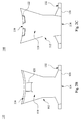
- Fig. 2A is a perspective view of a light-guiding pillar 110 of the vehicle lamp 100 illustrated in Fig. 1 .
- Fig. 2B is a top view of a light-guiding pillar 110 of the vehicle lamp 100 illustrated in Fig. 1 .
- Fig. 2C is a bottom view of a light-guiding pillar 110 of the vehicle lamp 100 illustrated in Fig. 1 .
- Fig. 2D is a schematic diagram of the light-guiding pillar 110 viewed along a sight line O1 illustrated in Fig. 2A .
- Fig. 2E is a schematic diagram of the light-guiding pillar 110 viewed along a sight line 02 illustrated in Fig. 2A .
- the light-guiding pillar 110 includes a major structure 112 and a light-guiding structure 120.
- the major structure 112 is a solid structure.
- the major structure 112 has the light incident surface 114, the light outgoing surface 116, an upper surface 118, and the bottom surface 119.
- the upper surface 118 and the bottom surface 119 are disposed between the light incident surface 114 and the light outgoing surface 116, in which the upper surface 118 and the bottom surface 119 are opposite to each other.
- the major structure 112 is configured to guide a portion of the light beam entering the major structure 112 through the light incident surface 114 to the light outgoing surface 116, in which the light beams guided from the light incident surface 114 to the light outgoing surface 116 are illustrated as light beams L1 and L2 in Fig. 2E .
- each of the upper surface 118 and the bottom surface 119 is a curved surface protruding outward from the major structure 112.
- the curved surfaces of the upper surface 118 and the bottom surface 119 a portion of the light beam entering through the light incident surface 114 can be focused on the light outgoing surface 116 so as to improve the optical performance of the major structure 112, but are not limited thereto.
- one of the upper surface 118 and the bottom surface 119 is a curved surface protruding outward from the major structure 112.
- the light-guiding structure 120 is disposed on the upper surface 118 and is adjacent to the light outgoing surface 116.
- the light-guiding structure 120 is configured to guide another portion of the light beam entering the major structure 112 through the light incident surface 114 from the upper surface 118 to the bottom surface 119 with passing through the bottom surface 119, in which the light beam guided from the upper surface 118 to the bottom surface 119 with passing through the bottom surface 119 is illustrated as the light beam L3 in Fig. 2E .
- the light-guiding structure 120 is a concave configuration configured to define a total internal reflection interface.
- the light-guiding pillar 110 can make the light beam provided by the light source 104 propagated from the light outgoing surface 116 and the bottom surface 119 of the major structure 112 to the condenser lens 106, in which the light outgoing surface 116 and the bottom surface 119 are surfaces of the major structure 112 that are adjacent to each other.
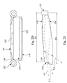
- Fig. 3 is a schematic diagram of a shape of a light beam projected by the vehicle lamp 100 illustrated in Fig. 1 .
- a testing screen a white screen or a white wall
- an illuminating area A (or a zone of brightness distribution) shown on the testing screen is illustrated in Fig. 3 .
- the illuminating area A includes a bright zone A1 (a zone within the solid line), a dark zone A2 (a zone within the dot line), and a cutoff line C between the bright zone A1 and the dark zone A2.
- the bright zone A1 of the illuminating area A is formed by projecting the light beam by the condenser lens 106, in which the light beam projected by the condenser lens 106 is provided by the light outgoing surface 116.
- the light beams L1, L2, and L3 provided by the light-guiding pillar 110 can be respectively projected to corresponding positions in the illuminating area A.
- the refract mechanism provided by the condenser lens 106 according to the imaging rule in a geometrical optics, the image formed by the light beam provided by the light-guiding pillar 110 and the image formed by the light beam projected by the condenser lens 106 are reverse (thus, after projected by the condenser lens 106, the image on the illuminating area A is upside down).
- the light beams L1 and L2 provided by the light-guiding pillar 110 are emitted toward the condenser lens 106 from the light outgoing surface 116, according to the refract mechanism provided by the condenser lens 106, the light beams L1 and L2 emitted from the light outgoing surface 116 are projected to the bright zone A1 (the bottom side in the testing screen) since the incident positions of the light beams L1 and L2 entering the condenser lens 106 are at the upper side of the optical axis 108.
- the light beam L3 provided by the light-guiding pillar 110 is emitted toward the condenser lens 106 from the bottom surface 119, according to the refract mechanism provided by the condenser lens 106, the light beam L3 emitted from the bottom surface 119 is projected to the dark zone A2 (the upper side in the testing screen) since the incident position of the light beam L3 entering the condenser lens 106 is at the bottom side of the optical axis 108.
- the light-guiding structure 120 can be taken as a brightness-improving structure for the dark zone.
- the light beam configured to improve the brightness in the dark zone A2 is a portion of the light beam provide by the light source 104, the brightness of the dark zone A2 after improving still can meet the regulations of vehicle lighting. The following descriptions are provided with respect to the structure configured to modify the shape of the projected light beam in detail.
- the light-guiding pillar 110 further includes a concave structure 122.
- the concave structure 122 is disposed on the bottom surface 119 and is adjacent to the light outgoing surface 116.
- the concave structure 122 is configured to define a boundary of the light beam emitted from the light outgoing surface 116.
- the bright zone A1 of the illuminating area A is formed by the light beam provided by the light outgoing surface 116, and the image formed by the light beam provided by the light-guiding pillar 110 and the image formed by the light beam projected by the condenser lens 106 are reverse.
- the concave structure 122 disposed on the bottom surface 119 can define a boundary B at an upper edge of the bright zone A1 of the illuminating area A.
- the concave structure 122 disposed on the bottom surface 119 of the major structure 112 and adjacent to the light outgoing surface 116 can define a shape near the cutoff line C in the illuminating area A, as shown in Fig. 3 . Therefore, by the concave structure 122, in the shape of the light beam provided by the vehicle lamp, testing points near the cutoff line C can be modified to meet the regulations of vehicle lighting.
- the light outgoing surface 116 is a surface that is curved and inward concave into the major structure 112.
- the light-guiding pillar 110 can effectively guide the light beam form the light incident surface 114 to the light outgoing surface 116.
- the light outgoing surface 116 that is curved and inward concave into the major structure 112 can provide the light beam with focusing on the light outgoing surface 116.
- a horizontal dimension of the light outgoing surface 116 can be greater than the light incident surface 114.
- a vertical distance between the light incident surface 114 and the light outgoing surface 116 is increasing from a boundary between the light outgoing surface 116 and the upper surface 118 to a boundary between the light outgoing surface 116 and the bottom surface 119.
- the vertical distance between the light incident surface 114 and the boundary between the light outgoing surface 116 and the upper surface 118 is distance D1
- the vertical distance between the light incident surface 114 and the boundary between the light outgoing surface 116 and the bottom surface 119 is distance D2
- the distance D1 is smaller than the distance D2.
- the light outgoing surface 116 is not a vertical surface.
- the light outgoing surface 116 can be taken as a backward surface, such that a focal plane 107 of the condenser lens 106 and the light outgoing surface 116 can at least intersect at a straight line.
- the light outgoing surface 116 is disposed near the focal plane 107 but is not totally matched with the focal plane 107 together.
- the illumination provided by the vehicle lamp 100 can be provided with an effect of misting.
- the boundaries between the light and dark zones provided by the vehicle lamp 100 can be misted.
- the backward light outgoing surface 116 can be configured to adjust an emitting angle of the light beam provided by the vehicle lamp 100, such that the projected location of the light beam provided by the vehicle lamp 100 on the ground (thus the ground in front of the vehicle lamp 100) can be controlled to be more close to a vehicle with the vehicle lamp 100 of the present disclosure.
- the light-guiding pillar 110 further includes a positioning portion 130.
- the positioning portion 130 is disposed on the major structure 112.
- the positioning portion 130 includes positioning holes 132.
- the vehicle lamp 100 further includes at least one positioning element 138.
- the positioning element 138 is fastened on the heat-dissipation base 102 via the positioning hole 132 to fix the major structure 112 on the heat-dissipation base 102, as show in Fig. 1 .
- the major structure 112 and the positioning portion 130 are formed by one-piece, but are not limited thereto.
- the vehicle lamp 100 of the present disclosure can improve the brightness in the dark zone A2 of the illuminating area A through the light-guiding structure 120, such that the dark zone A2 of the illuminating area A can have the certain brightness.
- the shape of the light or the illumination provided by the vehicle lamp 100 can be modified by the various structures of the light-guiding pillar 110, thereby improving the optical performance of the vehicle lamp 100 and making the shape of the light or the illumination provided by the vehicle lamp 100 meet the regulations of vehicle lighting.
- Fig. 4 is a side view of a light-guiding pillar 110 of a vehicle lamp 100 according to a second embodiment of the present disclosure.
- the difference between the present embodiment and the first embodiment is that the major structure 112 of the present embodiment is a hollow structure.
- the major structure 112 with the hollow structure can be taken as a shell structure.
- the major structure has a hole 128.
- the hole 128 is disposed at the bottom surface 119.
- the light-guiding structure 120 is configured to guide the light beam L3 entering the major structure 112 through the light incident surface 114 from the upper surface 118 to the bottom surface 119 with penetrating the bottom surface 119.
- the light beam L3 guided by the light-guiding structure 120 can pass through the bottom surface 119 via the hole 128.
- the light beam L3 passing through the bottom surface 119 via the hole 128 is collected by the condenser lens 106 (see Fig. 1 ), with the refract mechanism provided by the condenser lens 106 (see Fig. 1 ), the light beam L3 can be projected to the dark zone A2 of the illuminating area A (see Fig. 3 ).
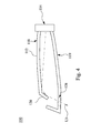
- Fig. 5 is a side view of a vehicle lamp 100 according to a third embodiment of the present disclosure.
- Fig. 6A is a perspective view of a light-guiding pillar 110 of the vehicle lamp 100 illustrated in Fig. 5 .
- Fig. 6B is a top view of a light-guiding pillar 110 of the vehicle lamp 100 illustrated in Fig. 5 .
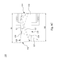
- Fig. 6C is a cross-sectional view taken along line II' of a light-guiding pillar 110 of the vehicle lamp 100 illustrated in Fig. 6B .
- Fig. 6D is a front view of a light-guiding pillar 110 of the vehicle lamp 100 illustrated in Fig. 5 .
- the difference between the present embodiment and the first embodiment is that the major structure 112 of the present embodiment further includes a light inlet portion 124 and a light outlet portion 126 connecting with each other.
- the major structure 112 can be taken as being formed by the light inlet portion 124 and the light outlet portion 126 connecting with each other and adjacent to each other. Moreover, the light incident surface 114 and light outgoing surface 116 are respectively disposed on the light inlet portion 124 and the light outlet portion 126, and are opposite to each other.
- At least one of the light inlet portion 124 and the light outlet portion 126 is composed by a partial graph of a three-dimensional curve.
- the light inlet portion 124 can be designed according to the partial graph of a three-dimensional ellipse. Since the graph composed by the three-dimensional ellipse has a focal point (or a focal plane), the light inlet portion 124 can effectively guide the light beam entering the light incident surface 114 to the light outlet portion 126 by this focal point (or a focal plane).
- the three-dimensional curve composing the light inlet portion 124 is configured to focus the light beam entering the major structure 112 from the light incident surface 124 onto the light outgoing surface 116 by the light inlet portion 124, as the light beams L1 and L2 illustrated in Figs. 6B and 6C .
- the three-dimensional curve is a three-dimensional conic section, but is not limited thereto.
- each of the light inlet portion 124 and the light outlet portion 126 is a solid structure, and the light-guiding structure 120 is the concave configuration configured to define the total internal reflection interface.
- the light-guiding structure 120 is configured to guide another portion of the light beam entering the major structure 112 through the light incident surface 114 from the upper surface 118 to the bottom surface 119 with passing through the bottom surface 119, as the light beam L3 illustrated in Fig. 6C .
- the light-guiding pillar 110 further includes the concave structure 122.
- the concave structure 122 is disposed on the bottom surface 119 and is adjacent to the light outgoing surface 116.
- the concave structure 122 is configured to define the boundary of the light beam emitted from the light outgoing surface 116.
- the image formed by the light beam provided by the light outgoing surface 116 of the light-guiding pillar 110 and the image formed by the light beam projected by the condenser lens 106 are reverse (the images are upside down to each other before and after projected by the condenser lens 106).
- the concave structure 122 disposed on the bottom surface 119 can define the boundary B at the upper edge of the bright zone A1 of the illuminating area A (see Fig. 3 ), such that the shape of the light beam provided by the vehicle lamp 100 can meet the regulations of vehicle lighting.
- the vertical distance between the light incident surface 114 and the light outgoing surface 116 is decreasing from the boundary between the light outgoing surface 116 and the upper surface 118 to the boundary between the light outgoing surface 116 and the bottom surface 119, as shown in Fig. 6C .
- the vertical distance between the light incident surface 114 and the boundary between the light outgoing surface 116 and the upper surface 118 is distance D1
- the vertical distance between the light incident surface 114 and the boundary between the light outgoing surface 116 and the bottom surface 119 is distance D2
- the distance D1 is smaller than the distance D2.
- the light outgoing surface 116 is not a vertical surface.
- the light outgoing surface 116 can be taken as a frontward surface, such that a portion of the focal plane 107 of the condenser lens 106 and the light outgoing surface 116 can be coincident with each other.
- the light outgoing surface 116 of the light-guiding pillar 110 is present within the focal plane 107.
- the light outgoing surface 116 of the light-guiding pillar 110 is present within the focal plane 107, the effect of the light/dark cutoff in the illumination provided by the vehicle lamp 100 can be improved. In other words, in the bright zone of the illuminating area provided by the vehicle lamp 100, the contrast between the bright zone and zones around there is enhanced.
- the light outgoing surface 116 may choose a proper arrangement of the light outgoing surface 116 to design or modify the illumination provided by the vehicle lamp 100.
- the light outgoing surface 116 can be designed as the frontward surface.
- the light outgoing surface 116 can be designed as the backward surface.
- the light-guiding pillar 110 further includes a frame 134 and a positioning portion 130.
- the frame 134 has an opening 136, in which the major structure 112 is disposed in the opening 136 to connect with the frame 134.
- the major structure 112 and the frame 134 can be formed by one-piece, but are not limited thereto.
- the positioning portion 130 is disposed on the frame 134, in which the positioning portion 130 includes the positioning holes 132.
- the positioning element 138 is fastened on the heat-dissipation base 102 via the positioning hole 132 to fix the major structure 112 on the heat-dissipation base 102.
- the light-guiding structure by the light-guiding structure, the light beam provided by the light source can be emitted from the light outgoing surface and the bottom surface of the light-guiding pillar, in which the light beams emitted from the light outgoing surface and the bottom surface of the light-guiding pillar can be respectively projected to the bright zone and the dark zone of the illuminating area. Therefore, in the illuminating area that the vehicle lamp projects the light beam thereon, the dark zone is not complete dark but a little bright.
- the light-guiding structure can be taken as the brightness-improving structure for the dark zone, such that the brightness distribution in the illuminating area provided by the vehicle lamp can meet the regulations of vehicle lighting.
- the concave structure disposed on the major structure can define the boundary at the upper edge of the bright zone.
- the testing points near the cutoff line can be modified to meet the regulations of vehicle lighting.
Landscapes
- Engineering & Computer Science (AREA)
- General Engineering & Computer Science (AREA)
- Physics & Mathematics (AREA)
- Optics & Photonics (AREA)
- Microelectronics & Electronic Packaging (AREA)
- General Physics & Mathematics (AREA)
- Mechanical Engineering (AREA)
- Non-Portable Lighting Devices Or Systems Thereof (AREA)
- Light Guides In General And Applications Therefor (AREA)
- Lenses (AREA)
- Securing Globes, Refractors, Reflectors Or The Like (AREA)
- Planar Illumination Modules (AREA)
Applications Claiming Priority (1)
| Application Number | Priority Date | Filing Date | Title |
|---|---|---|---|
| TW104121879A TWI607181B (zh) | 2015-07-06 | 2015-07-06 | 導光柱與使用其的車用燈具 |
Publications (1)
| Publication Number | Publication Date |
|---|---|
| EP3115682A1 true EP3115682A1 (de) | 2017-01-11 |
Family
ID=54495499
Family Applications (1)
| Application Number | Title | Priority Date | Filing Date |
|---|---|---|---|
| EP16176111.9A Withdrawn EP3115682A1 (de) | 2015-07-06 | 2016-06-24 | Lichtleitende säule und fahrzeuglampe damit |
Country Status (5)
| Country | Link |
|---|---|
| US (2) | US9964272B2 (de) |
| EP (1) | EP3115682A1 (de) |
| JP (1) | JP6118866B2 (de) |
| CN (2) | CN108954212A (de) |
| TW (1) | TWI607181B (de) |
Cited By (3)
| Publication number | Priority date | Publication date | Assignee | Title |
|---|---|---|---|---|
| EP3453951A1 (de) * | 2017-09-07 | 2019-03-13 | T.Y.C. Brother Industrial Co., Ltd. | Lampenlinse |
| WO2020074327A1 (de) * | 2018-10-11 | 2020-04-16 | HELLA GmbH & Co. KGaA | Scheinwerfer für fahrzeuge |
| EP4180710A1 (de) * | 2021-11-12 | 2023-05-17 | ZKW Group GmbH | Beleuchtungsvorrichtung für kraftfahrzeugscheinwerfer |
Families Citing this family (14)
| Publication number | Priority date | Publication date | Assignee | Title |
|---|---|---|---|---|
| US10775011B2 (en) | 2016-03-24 | 2020-09-15 | Koito Manufacturing Co., Ltd. | Vehicle lamp, vehicle lamp control system, and vehicle provided with vehicle lamp and vehicle lamp control system |
| TWI616685B (zh) * | 2016-05-31 | 2018-03-01 | 隆達電子股份有限公司 | 光源系統 |
| FR3055400B1 (fr) * | 2016-09-01 | 2019-06-28 | Valeo Vision | Module optique pour eclairer des points de portique |
| EP3667161A1 (de) * | 2016-09-30 | 2020-06-17 | H.A. Automotive Systems, Inc. | Kondensator für abblendlichtmodul eines fahrzeugs |
| KR101907372B1 (ko) * | 2017-04-26 | 2018-10-12 | 현대모비스 주식회사 | 헤드램프 장치 |
| KR102409832B1 (ko) * | 2017-09-20 | 2022-06-17 | 에스엘 주식회사 | 차량용 램프 |
| JP2019175826A (ja) | 2018-03-29 | 2019-10-10 | パナソニックIpマネジメント株式会社 | 移動体照明装置及び移動体 |
| CN108488756A (zh) * | 2018-06-01 | 2018-09-04 | 江苏信利电子有限公司 | 机动车前大灯及机动车 |
| TWI694224B (zh) * | 2019-10-07 | 2020-05-21 | 坦德科技股份有限公司 | 車用照明裝置 |
| US11112081B2 (en) * | 2019-12-02 | 2021-09-07 | Tan De Tech Co., Ltd. | Light device with hollow column light guide for vehicle |
| JP7423299B2 (ja) * | 2019-12-19 | 2024-01-29 | スタンレー電気株式会社 | 車両用灯具 |
| WO2021121131A1 (zh) * | 2019-12-20 | 2021-06-24 | 华域视觉科技(上海)有限公司 | 光学元件、车灯模组、车灯及车辆 |
| CN113494700A (zh) * | 2020-03-20 | 2021-10-12 | 华域视觉科技(上海)有限公司 | 一种近光初级光学元件、车灯模组、车灯和车辆 |
| WO2021246065A1 (ja) * | 2020-06-02 | 2021-12-09 | ミネベアミツミ株式会社 | 照明装置 |
Citations (10)
| Publication number | Priority date | Publication date | Assignee | Title |
|---|---|---|---|---|
| EP1630576A2 (de) * | 2004-08-27 | 2006-03-01 | Osram Opto Semiconductors GmbH | Leuchtmittel mit vorgegebener Abstrahlcharakteristik und Primäroptikelement für ein Leuchtmittel |
| FR2907535A1 (fr) * | 2006-10-23 | 2008-04-25 | Zizala Lichtsysteme Gmbh | Element optique pour phare de vehicule automobile |
| US20090016074A1 (en) * | 2007-07-09 | 2009-01-15 | Magna International Inc. | Semiconductor light engine using glass light pipes |
| US20100103694A1 (en) * | 2008-10-23 | 2010-04-29 | Hella Kg Hueck & Co. | Light guide array |
| DE102011000697A1 (de) * | 2011-02-14 | 2012-08-16 | Hella Kgaa Hueck & Co. | Beleuchtungsvorrichtung für Fahrzeuge |
| EP2525141A1 (de) * | 2010-01-12 | 2012-11-21 | Koito Manufacturing Co., Ltd. | Fahrzeugscheinwerfer |
| WO2014056568A1 (de) * | 2012-10-14 | 2014-04-17 | Docter Optics Se | Vorsatzoptikarray für einen scheinwerfer, optisches element umfassend zwei vorsatzoptikarray und verfahren zur dessen herstellung |
| WO2014174843A1 (ja) * | 2013-04-26 | 2014-10-30 | 三菱電機株式会社 | 車両用前照灯モジュール、車両用前照灯ユニット及び車両用前照灯装置 |
| DE102014007185A1 (de) * | 2013-06-18 | 2014-12-18 | Docter Optics Se | Optisches Element für einen Fahrzeugscheinwerfer |
| US20150176793A1 (en) * | 2013-12-23 | 2015-06-25 | Hyundai Motor Company | Head lamp apparatus for vehicles |
Family Cites Families (34)
| Publication number | Priority date | Publication date | Assignee | Title |
|---|---|---|---|---|
| JPS61127506U (de) * | 1985-01-30 | 1986-08-11 | ||
| JP3337560B2 (ja) * | 1994-07-21 | 2002-10-21 | 株式会社デンソー | 車両用灯具装置 |
| US6179454B1 (en) * | 1998-02-06 | 2001-01-30 | North American Lighting, Inc. | Illumination system for vehicle running boards and the area below the running board |
| DE50015035D1 (de) * | 1999-01-21 | 2008-04-24 | Fer Fahrzeugelektrik Gmbh | Fahrzeugleuchte |
| JP4030728B2 (ja) * | 2001-04-25 | 2008-01-09 | 株式会社小糸製作所 | 車輌用前照灯 |
| US6769798B2 (en) * | 2002-04-11 | 2004-08-03 | E'sam Co.,. Ltd. | Side mirror cover and cover lamp to be used therefor |
| DE102004015544B4 (de) * | 2003-03-31 | 2009-05-07 | Toyoda Gosei Co., Ltd. | LED-Leuchte und Seitenspiegelvorrichtung |
| US7458695B2 (en) * | 2005-06-20 | 2008-12-02 | Continental Automotive Systems Us, Inc. | High light-efficiency illumination cluster |
| DE102006044641A1 (de) * | 2006-09-19 | 2008-03-27 | Schefenacker Vision Systems Germany Gmbh | Leuchteinheit mit Leuchtdiode, Lichtleitkörper und Sekundärlinse |
| DE102006044640A1 (de) * | 2006-09-19 | 2008-03-27 | Schefenacker Vision Systems Germany Gmbh | Leuchteinheit zur Fern- und Abblendlichterzeugung |
| JP4930787B2 (ja) * | 2007-07-27 | 2012-05-16 | スタンレー電気株式会社 | 車両用灯具、及び、車両用灯具に用いられる導光レンズ |
| JP5069985B2 (ja) * | 2007-09-13 | 2012-11-07 | 株式会社小糸製作所 | 車両用前照灯の灯具ユニットおよび車両用前照灯 |
| JP2009218076A (ja) * | 2008-03-10 | 2009-09-24 | Koito Mfg Co Ltd | 車両用灯具 |
| US8152352B2 (en) * | 2009-01-02 | 2012-04-10 | Rambus International Ltd. | Optic system for light guide with controlled output |
| CN103890622A (zh) * | 2011-11-03 | 2014-06-25 | 皇家飞利浦有限公司 | 特别地用于自行车的led尾灯 |
| JP5991458B2 (ja) * | 2011-11-24 | 2016-09-14 | スタンレー電気株式会社 | 車両用灯具ユニット |
| CN202469885U (zh) * | 2011-12-22 | 2012-10-03 | 堤维西交通工业股份有限公司 | 导光条光学构造 |
| JP5835828B2 (ja) * | 2012-03-23 | 2015-12-24 | Necディスプレイソリューションズ株式会社 | 光源装置、投写型表示装置及び照明方法 |
| DE102013006707A1 (de) * | 2012-05-26 | 2013-11-28 | Docter Optics Se | Fahrzeugscheinwerfer |
| WO2014156668A1 (ja) * | 2013-03-27 | 2014-10-02 | 株式会社小糸製作所 | 車輌用灯具 |
| CN203215562U (zh) * | 2013-04-07 | 2013-09-25 | 湖南福安工业有限公司 | 条状光型灯具的光学透镜 |
| CN103206639B (zh) * | 2013-04-19 | 2015-06-10 | 四川九洲光电科技股份有限公司 | Led的柔性发光结构 |
| WO2014192797A1 (ja) * | 2013-05-29 | 2014-12-04 | テイ・エス テック株式会社 | 車両用発光部品 |
| TW201447405A (zh) * | 2013-06-07 | 2014-12-16 | Ta Yih Ind Co Ltd | 異形導光條光學結構 |
| DE102013212352A1 (de) * | 2013-06-26 | 2014-12-31 | Automotive Lighting Reutlingen Gmbh | Kraftfahrzeugbeleuchtungseinrichtung mit einer Einkoppeloptik und einer Transport- und Umformoptik |
| JP2015011976A (ja) * | 2013-07-02 | 2015-01-19 | 東芝ライテック株式会社 | 発光装置および照明装置 |
| CN105556200B (zh) * | 2013-09-17 | 2016-12-21 | 三菱电机株式会社 | 车载用前照灯 |
| JP6222557B2 (ja) * | 2013-10-17 | 2017-11-01 | スタンレー電気株式会社 | 車両用灯具 |
| CN105745488B (zh) * | 2013-11-19 | 2018-05-18 | 三菱电机株式会社 | 前照灯模块和前照灯装置 |
| JP6232963B2 (ja) * | 2013-11-19 | 2017-11-22 | スタンレー電気株式会社 | 車両用前照灯 |
| CN104676357B (zh) * | 2013-11-30 | 2018-05-01 | 赛恩倍吉科技顾问(深圳)有限公司 | 发光装置及背光模块 |
| CN203949100U (zh) * | 2014-06-18 | 2014-11-19 | 立达信绿色照明股份有限公司 | 导光柱及灯具 |
| EP3392685B1 (de) * | 2015-01-19 | 2021-03-03 | SMR Patents S.à.r.l. | Rückblickvorrichtung für ein kraftfahrzeug |
| US10060594B2 (en) * | 2015-01-19 | 2018-08-28 | SMR Patents S.à.r.l. | Light guiding device |
-
2015
- 2015-07-06 TW TW104121879A patent/TWI607181B/zh active
- 2015-08-05 CN CN201810564166.4A patent/CN108954212A/zh active Pending
- 2015-08-05 CN CN201510472843.6A patent/CN105066062B/zh active Active
- 2015-09-28 JP JP2015189094A patent/JP6118866B2/ja active Active
- 2015-10-13 US US14/881,299 patent/US9964272B2/en active Active
-
2016
- 2016-02-26 US US15/054,703 patent/US9903553B2/en active Active
- 2016-06-24 EP EP16176111.9A patent/EP3115682A1/de not_active Withdrawn
Patent Citations (10)
| Publication number | Priority date | Publication date | Assignee | Title |
|---|---|---|---|---|
| EP1630576A2 (de) * | 2004-08-27 | 2006-03-01 | Osram Opto Semiconductors GmbH | Leuchtmittel mit vorgegebener Abstrahlcharakteristik und Primäroptikelement für ein Leuchtmittel |
| FR2907535A1 (fr) * | 2006-10-23 | 2008-04-25 | Zizala Lichtsysteme Gmbh | Element optique pour phare de vehicule automobile |
| US20090016074A1 (en) * | 2007-07-09 | 2009-01-15 | Magna International Inc. | Semiconductor light engine using glass light pipes |
| US20100103694A1 (en) * | 2008-10-23 | 2010-04-29 | Hella Kg Hueck & Co. | Light guide array |
| EP2525141A1 (de) * | 2010-01-12 | 2012-11-21 | Koito Manufacturing Co., Ltd. | Fahrzeugscheinwerfer |
| DE102011000697A1 (de) * | 2011-02-14 | 2012-08-16 | Hella Kgaa Hueck & Co. | Beleuchtungsvorrichtung für Fahrzeuge |
| WO2014056568A1 (de) * | 2012-10-14 | 2014-04-17 | Docter Optics Se | Vorsatzoptikarray für einen scheinwerfer, optisches element umfassend zwei vorsatzoptikarray und verfahren zur dessen herstellung |
| WO2014174843A1 (ja) * | 2013-04-26 | 2014-10-30 | 三菱電機株式会社 | 車両用前照灯モジュール、車両用前照灯ユニット及び車両用前照灯装置 |
| DE102014007185A1 (de) * | 2013-06-18 | 2014-12-18 | Docter Optics Se | Optisches Element für einen Fahrzeugscheinwerfer |
| US20150176793A1 (en) * | 2013-12-23 | 2015-06-25 | Hyundai Motor Company | Head lamp apparatus for vehicles |
Cited By (4)
| Publication number | Priority date | Publication date | Assignee | Title |
|---|---|---|---|---|
| EP3453951A1 (de) * | 2017-09-07 | 2019-03-13 | T.Y.C. Brother Industrial Co., Ltd. | Lampenlinse |
| WO2020074327A1 (de) * | 2018-10-11 | 2020-04-16 | HELLA GmbH & Co. KGaA | Scheinwerfer für fahrzeuge |
| US11248766B2 (en) | 2018-10-11 | 2022-02-15 | HELLA GmbH & Co. KGaA | Headlight for vehicles |
| EP4180710A1 (de) * | 2021-11-12 | 2023-05-17 | ZKW Group GmbH | Beleuchtungsvorrichtung für kraftfahrzeugscheinwerfer |
Also Published As
| Publication number | Publication date |
|---|---|
| CN105066062B (zh) | 2018-12-21 |
| TW201702523A (zh) | 2017-01-16 |
| US20170009951A1 (en) | 2017-01-12 |
| CN108954212A (zh) | 2018-12-07 |
| US9903553B2 (en) | 2018-02-27 |
| JP6118866B2 (ja) | 2017-04-19 |
| CN105066062A (zh) | 2015-11-18 |
| JP2017016990A (ja) | 2017-01-19 |
| US20170009950A1 (en) | 2017-01-12 |
| US9964272B2 (en) | 2018-05-08 |
| TWI607181B (zh) | 2017-12-01 |
Similar Documents
| Publication | Publication Date | Title |
|---|---|---|
| US9903553B2 (en) | Light-guiding pillar and vehicle lamp using the same | |
| JP6812411B2 (ja) | 車両用灯具、車両用灯具制御システムおよびこれらを備えた車両 | |
| US20170276310A1 (en) | Vehicle lamp and vehicle having the same | |
| US20170276309A1 (en) | Vehicle lamp and vehicle having the same | |
| KR200479892Y1 (ko) | 최대 집광효과에 도달할 수 있는 조명장치 | |
| US7201499B2 (en) | Vehicle lamp unit | |
| CN108980774B (zh) | 照明装置以及车辆用前照灯 | |
| US7954987B2 (en) | Vehicle lamp | |
| US8801221B2 (en) | Lens structure, light source device and light source module | |
| JP2010080306A (ja) | 車両前照灯用灯具ユニット | |
| JP6407407B2 (ja) | 光源装置及び照明装置 | |
| TWI506229B (zh) | 發光裝置及其透鏡 | |
| US10359167B2 (en) | Vehicular lighting | |
| JP6706183B2 (ja) | 光学素子 | |
| WO2019210709A1 (zh) | 灯具 | |
| US9862306B2 (en) | Vehicle decorative lighting device and vehicle lamp | |
| CN104736928B (zh) | 用于发光模块的光罩 | |
| TWI582335B (zh) | Lights | |
| CN109790966A (zh) | 具有空间上分离的固态照明元件的灯具 | |
| JP7447618B2 (ja) | 投光器 | |
| JP2008091349A (ja) | 光源ユニットおよび車両用灯具 | |
| JP2023012692A (ja) | 照明装置 | |
| RU2626059C1 (ru) | Способ рециркуляции света и светодиодный модуль рециркуляции | |
| CN204083875U (zh) | 照明装置 | |
| JP6345539B2 (ja) | 光束制御部材および発光装置 |
Legal Events
| Date | Code | Title | Description |
|---|---|---|---|
| PUAI | Public reference made under article 153(3) epc to a published international application that has entered the european phase |
Free format text: ORIGINAL CODE: 0009012 |
|
| AK | Designated contracting states |
Kind code of ref document: A1 Designated state(s): AL AT BE BG CH CY CZ DE DK EE ES FI FR GB GR HR HU IE IS IT LI LT LU LV MC MK MT NL NO PL PT RO RS SE SI SK SM TR |
|
| AX | Request for extension of the european patent |
Extension state: BA ME |
|
| 17P | Request for examination filed |
Effective date: 20170706 |
|
| RBV | Designated contracting states (corrected) |
Designated state(s): AL AT BE BG CH CY CZ DE DK EE ES FI FR GB GR HR HU IE IS IT LI LT LU LV MC MK MT NL NO PL PT RO RS SE SI SK SM TR |
|
| 17Q | First examination report despatched |
Effective date: 20180703 |
|
| RIC1 | Information provided on ipc code assigned before grant |
Ipc: F21S 41/24 20180101AFI20181130BHEP |
|
| GRAP | Despatch of communication of intention to grant a patent |
Free format text: ORIGINAL CODE: EPIDOSNIGR1 |
|
| INTG | Intention to grant announced |
Effective date: 20190213 |
|
| STAA | Information on the status of an ep patent application or granted ep patent |
Free format text: STATUS: THE APPLICATION IS DEEMED TO BE WITHDRAWN |
|
| 18D | Application deemed to be withdrawn |
Effective date: 20190625 |