EP3114014B1 - System for fastening a plurality of bodywork elements - Google Patents
System for fastening a plurality of bodywork elements Download PDFInfo
- Publication number
- EP3114014B1 EP3114014B1 EP15709225.5A EP15709225A EP3114014B1 EP 3114014 B1 EP3114014 B1 EP 3114014B1 EP 15709225 A EP15709225 A EP 15709225A EP 3114014 B1 EP3114014 B1 EP 3114014B1
- Authority
- EP
- European Patent Office
- Prior art keywords
- plate
- fastening
- fastening system
- section
- interface
- Prior art date
- Legal status (The legal status is an assumption and is not a legal conclusion. Google has not performed a legal analysis and makes no representation as to the accuracy of the status listed.)
- Not-in-force
Links
- 239000000463 material Substances 0.000 claims description 9
- 239000011324 bead Substances 0.000 claims description 3
- 238000004080 punching Methods 0.000 claims description 3
- 238000005452 bending Methods 0.000 claims 1
- BASFCYQUMIYNBI-UHFFFAOYSA-N platinum Chemical compound [Pt] BASFCYQUMIYNBI-UHFFFAOYSA-N 0.000 description 20
- 230000007547 defect Effects 0.000 description 4
- 238000005553 drilling Methods 0.000 description 2
- 238000005253 cladding Methods 0.000 description 1
- 238000005304 joining Methods 0.000 description 1
- 238000004519 manufacturing process Methods 0.000 description 1
- 229910052697 platinum Inorganic materials 0.000 description 1
- 230000001737 promoting effect Effects 0.000 description 1
- 238000003466 welding Methods 0.000 description 1
Images


Classifications
-
- B—PERFORMING OPERATIONS; TRANSPORTING
- B62—LAND VEHICLES FOR TRAVELLING OTHERWISE THAN ON RAILS
- B62D—MOTOR VEHICLES; TRAILERS
- B62D27/00—Connections between superstructure or understructure sub-units
- B62D27/06—Connections between superstructure or understructure sub-units readily releasable
-
- B—PERFORMING OPERATIONS; TRANSPORTING
- B62—LAND VEHICLES FOR TRAVELLING OTHERWISE THAN ON RAILS
- B62D—MOTOR VEHICLES; TRAILERS
- B62D25/00—Superstructure or monocoque structure sub-units; Parts or details thereof not otherwise provided for
- B62D25/08—Front or rear portions
- B62D25/16—Mud-guards or wings; Wheel cover panels
- B62D25/163—Mounting devices
Definitions
- the invention relates to the field of the automobile and more particularly to the fastening devices of the bodywork elements on the body of a motor vehicle.
- the body of the motor vehicle represents the frame of the latter. This box is provided with a whole series of parts of dressing also called elements of bodywork.
- the trim parts contribute to the aerodynamics of the vehicle as well as the aesthetics by promoting the style of a car brand.
- At the front of the vehicle on each side in particular, three body elements are mounted on the body. These three elements are the mudguard, the lower body trim and the front fender.
- the mudguard is a part usually made of a semi-rigid material. This has a semicircular shape overhanging the front wheel to prevent projectiles (chippings, mud) launched at high speed do not damage the motor vehicle.
- the rocker cover is a trim piece that extends between the front and rear wheels.
- the hubcap gives the vehicle a pleasant aesthetic appearance. It also contributes to the aerodynamics of the vehicle.
- the front fender gives aesthetics and aerodynamics to the motor vehicle.
- U.S. Patent No. 8,083,285 discloses the attachment of the mudguard and the rocker cover directly to the body of the motor vehicle with a screw.
- the mudguard is sandwiched between the front end of the lower body trim and the body of the motor vehicle.
- a screw is then inserted into an orifice made at the same time in the lower body trim, the mudguard and the body of the motor vehicle.
- This type of attachment has many disadvantages. A first of them is that it is necessary to position the piercing of the underside trim and the mudguard opposite the drilling in the body of the motor vehicle. A screw is then inserted, the latter to fix the hubcap and mudguard on the body of the motor vehicle.
- a second disadvantage is that the wing is fixed in another place on the body of the motor vehicle. This configuration generates gaps between the trim elements that are not constant given the tolerance intervals of one vehicle to another. In other words, the general appearance of the motor vehicle has visible defects from one vehicle to another and on the same assembly line.
- Fixing body parts on the body of a motor vehicle is all the easier as it is performed on a single interface. This also avoids appearance defects from one vehicle to another.
- the figure 1 represents a vehicle 1 automobile equipped with a system 2 for fixing a plurality of elements 3, 4, 5 of bodywork on a body 6 of a motor vehicle.
- the fixing system 2 comprises an interface 7 shown in detail on the figures 2 and 3 and attached fastening means such as staples 8 and screws.
- Each part extends in a plane, these planes being substantially perpendicular two by two.
- the first portion 9 extends in the plane XZ, the latter comprises a first plate 12 and a second plate 13 on which are respectively arranged an orifice 14 and a hole 15.
- the first plate 12 and the second plate 13 are spaced apart. one from the other by a chicane 16.
- the second part 10 comprises a third plate 17, on which is pierced a notch 18 of substantially square shape.
- the second part 10 is connected to the first part 9 by a connecting section 19 .
- the connecting section 19 faces the second plate 13 of the first part 9.
- the second plate 13 and the connecting section 19 are kept in intimate contact thanks to a clinche 20 and an electric welding point shown in the figures by a cross (PSE).
- the clinche 20 is formed by stamping the material on the side of the connecting section 19 .
- the connecting section 19 extends the first part 9 at one of its ends by a bead 21 of material formed by folding 180 ° of the interface 7. At the other end, the junction with the second part 10 is made with a first turn 22. Two bulldozers 23 make it possible to freeze the angle between the second part 10 and the connecting section 19 . Bulldozers 23 are formed by punching the material to give it structural rigidity.
- the connecting section 19 further comprises an opening 24 to allow free passage of a staple 8 through the hole 15.
- the third section 11 extends in the XY plane in cantilever above the first part 9, with which it is connected via a junction 25 curve.
- the third part 11 has a fourth plate 26 and a fifth plate 27.
- the fourth plate 26 and the fifth plate 27 extend respectively cantilever over the first plate 12 and the second plate 13.
- the fourth platinum 26 and the fifth plate 27 are connected by a curved section 28 which extends over the length of the baffle 16 so that the fifth plate 27 is raised relative to the fourth plate 26.
- the fifth plate 27 comprises a drilling 29 on which is fixed a nut 30.
- the nut 30 can thus receive a screw for fixing a bodywork element.
- the fifth plate 27 comprises at a distal end a zone 31 projecting from the fourth plate 26. This specific geometry allows to adapt to the particularisms that present the models of the various motor vehicles.
- the interface 7 finally comprises a fastening tab 32 connected to the second part 10 via a joining section 33 .
- the connecting section 33 is connected at one of its ends to the second portion 10 via a first curvature 34 on which two bulldozers 23 are arranged. At the other end thereof, the connection with the tab 32 of fixation is done through a second curvature 35 on which is also arranged a bulldozer 23.
- the interface 7 is positioned at the wheel passage 36 on the front end of the lower body 37 .
- the bracket 32 and the first plate 12 are both brought into contact with the body 6 of the motor vehicle, making sure that the orifice 14 is indexed on an indexing hole made in the body 6 of the motor vehicle.
- the rest of the interface 7 is cantilevered.
- the interface 7 is then fixed on the body 6 of the motor vehicle with the aid of several EPS.
- two PES are made at the first plate 12 on either side of the orifice 14 and another PSE is made at the bracket 32 .
- the assembly of the elements 3, 4, 5, bodywork can then begin.
- the order of assembly of the elements 3, 4, 5 of bodywork does not matter, so that we can start with any element.
- a first element in this case a hubcap 3 rocker is reported on the interface 7.
- Two staples 8 have previously been pre-positioned on the hubcap 3 rocker.
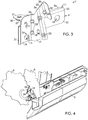
- the embellisher 3 sill is snapped onto the first portion 9 of the interface 7 as illustrated on the figure 4 .
- a second body element namely the mudguard 5 is attached to the interface 7.
- An anchor (not shown) mounted in the mudguard is placed opposite the notch 18 made in the second part 10 and a screw (not shown) makes it possible to secure it to the interface 7.
- a third body element namely the wing 4 is attached to the interface 7.
- a screw (not shown) is inserted into the nut 30 and the wing 4 is fixed to the third portion 11.
- the interface attachment system 7 has several advantages.
- a first advantage is that the attachment is easy because several body elements 3, 4, 5 are fixed on one and the same piece.
- a second advantage is that the appearance of the body is substantially identical from one vehicle to another, the attachment to a single piece to avoid errors in dimensions related to manufacturing defects.
- a third advantage provided is that, in view of the fact that the interface is partly cantilevered, this avoids the rocker cover to be cantilevered beyond the fixation way too important. This reduces the risk of damage to the trim 3 rocker.
Description
L'invention a trait au domaine de l'automobile et plus particulièrement aux dispositifs de fixation des éléments de carrosserie sur la caisse d'un véhicule automobile.The invention relates to the field of the automobile and more particularly to the fastening devices of the bodywork elements on the body of a motor vehicle.
La caisse du véhicule automobile représente l'ossature de ce dernier. Cette caisse est pourvue de toute une série de pièces d'habillage aussi appelées éléments de carrosserie. Les pièces d'habillage contribuent à l'aérodynamique du véhicule ainsi qu'à l'esthétique en promouvant le style d'une marque automobile. A l'avant du véhicule, de chaque côté notamment, trois éléments de carrosserie sont montés sur la caisse. Ces trois éléments sont le pare-boue, l'enjoliveur bas de caisse et l'aile avant.The body of the motor vehicle represents the frame of the latter. This box is provided with a whole series of parts of dressing also called elements of bodywork. The trim parts contribute to the aerodynamics of the vehicle as well as the aesthetics by promoting the style of a car brand. At the front of the vehicle, on each side in particular, three body elements are mounted on the body. These three elements are the mudguard, the lower body trim and the front fender.
Le pare-boue est une pièce généralement fabriquée dans un matériau semi-rigide. Celui-ci présente une forme semi-circulaire surplombant la roue avant afin d'éviter que des projectiles (gravillons, boue) lancés à grande vitesse n'abîment le véhicule automobile.The mudguard is a part usually made of a semi-rigid material. This has a semicircular shape overhanging the front wheel to prevent projectiles (chippings, mud) launched at high speed do not damage the motor vehicle.
L'enjoliveur bas de caisse est une pièce d'habillage qui s'étend entre les roues avant et arrière. L'enjoliveur offre au véhicule un aspect esthétique agréable. Il contribue également à l'aérodynamique du véhicule.The rocker cover is a trim piece that extends between the front and rear wheels. The hubcap gives the vehicle a pleasant aesthetic appearance. It also contributes to the aerodynamics of the vehicle.
A l'instar de l'enjoliveur bas de caisse, l'aile avant confère esthétique et aérodynamique au véhicule automobile.Like the underbody trim, the front fender gives aesthetics and aerodynamics to the motor vehicle.
Le brevet américain n° 8,083,285 décrit la fixation du pare-boue et de l'enjoliveur bas de caisse directement sur la caisse du véhicule automobile à l'aide d'une vis. Le pare-boue est pris en sandwich entre l'extrémité avant de l'enjoliveur bas de caisse et la caisse du véhicule automobile. Une vis est alors insérée dans un orifice pratiqué à la fois dans l'enjoliveur bas de caisse, le pare-boue et la caisse du véhicule automobile.U.S. Patent No. 8,083,285 discloses the attachment of the mudguard and the rocker cover directly to the body of the motor vehicle with a screw. The mudguard is sandwiched between the front end of the lower body trim and the body of the motor vehicle. A screw is then inserted into an orifice made at the same time in the lower body trim, the mudguard and the body of the motor vehicle.
Ce type de fixation présente de nombreux inconvénients. Un premier d'entre eux est qu'il est nécessaire de positionner le perçage de l'enjoliveur bas de caisse et du pare-boue en regard du perçage pratiqué dans la caisse du véhicule automobile. Une vis est ensuite insérée, celle-ci permettant de fixer l'enjoliveur et le pare-boue sur la caisse du véhicule automobile.This type of attachment has many disadvantages. A first of them is that it is necessary to position the piercing of the underside trim and the mudguard opposite the drilling in the body of the motor vehicle. A screw is then inserted, the latter to fix the hubcap and mudguard on the body of the motor vehicle.
Un deuxième inconvénient est que l'aile est fixée en un autre endroit sur la caisse du véhicule automobile. Cette configuration génère des espaces entre les éléments d'habillage qui ne sont pas constants compte tenu des intervalles de tolérance d'un véhicule à l'autre. Autrement dit, l'aspect général du véhicule automobile présente des défauts visibles d'un véhicule à un autre et ce, sur une même chaîne de montage.A second disadvantage is that the wing is fixed in another place on the body of the motor vehicle. This configuration generates gaps between the trim elements that are not constant given the tolerance intervals of one vehicle to another. In other words, the general appearance of the motor vehicle has visible defects from one vehicle to another and on the same assembly line.
Plusieurs objectifs sont poursuivis parmi lesquels peuvent être cités :
- rendre aisée la fixation des éléments d'habillage sur la caisse de véhicule automobile,
- fixer au moins trois pièces d'habillage sur un seul système de fixation,
- éviter les défauts esthétiques liés au fait que les pièces d'habillage ne sont pas fixées au même endroit sur la caisse de véhicule automobile.
- make it easy to fix the cladding elements on the motor vehicle body,
- fix at least three pieces of clothing on a single fastening system,
- avoid aesthetic defects related to the fact that the trim parts are not fixed at the same place on the body of a motor vehicle.
A cet effet, il est proposé en premier lieu un système de fixation d'éléments de carrosserie sur une caisse de véhicule automobile, ce système de fixation comprenant une interface se présentant sous la forme d'une pièce monobloc et solidaire de la caisse de véhicule automobile, cette interface comprenant :
- une première partie comprenant des moyens de fixation destinés à recevoir un enjoliveur bas de caisse ;
- une deuxième partie comprenant des moyens de fixation destinés à recevoir un pare-boue ;
- une troisième partie comprenant des moyens de fixation destinés à recevoir une aile avant.
- a first part comprising fastening means for receiving a lower body trim;
- a second part comprising fixing means for receiving a mudguard;
- a third part comprising fixing means for receiving a front wing.
La fixation des éléments de carrosserie sur la caisse de véhicule automobile est d'autant plus aisée que celle-ci s'effectue sur une seule et même interface. Ceci évite également les défauts d'aspects d'un véhicule à l'autre.Fixing body parts on the body of a motor vehicle is all the easier as it is performed on a single interface. This also avoids appearance defects from one vehicle to another.
Diverses caractéristiques supplémentaires peuvent être prévues, seules ou en combinaison :
- la première partie, la deuxième partie et la troisième partie s'étendent chacune dans des plans sensiblement perpendiculaires deux à deux ;
- la première partie comprend une première platine et une deuxième platine, ces dernières étant espacées l'une de l'autre par une chicane ;
- la deuxième partie et la section de liaison présentent à leur jonction un premier virage sur lequel sont formés deux bulldozers par poinçonnage de la matière ;
- la deuxième partie comprend une troisième platine, la deuxième partie et la première partie étant reliées par l'intermédiaire d'une section de liaison faisant face à la deuxième platine, la section de liaison et la première partie présentant à leur jonction un bourrelet formé par pliage de la matière ;
- la troisième partie s'étend en porte-à-faux au-dessus de la première partie avec laquelle elle est reliée par l'intermédiaire d'une jonction courbe ;
- la troisième partie comprend une quatrième platine et une cinquième platine s'étendant respectivement en porte-à-faux au-dessus de la première platine et de la deuxième platine ;
- l'interface comprend une patte de fixation reliée à la deuxième partie par l'intermédiaire d'une section de jonction, la section de jonction étant connectée à l'une de ses extrémités avec la deuxième partie par l'intermédiaire d'une première courbure et à l'autre de ses extrémités avec la patte de fixation par l'intermédiaire d'une seconde courbure ;
- sont respectivement agencés sur la première platine, la deuxième platine, la troisième platine, la cinquième platine, un orifice, un trou, une échancrure et un perçage destinés à recevoir des agrafes ou des vis ;
- la quatrième platine et la cinquième platine sont espacées l'une de l'autre par l'intermédiaire d'une section courbe, la section courbe s'étendant en porte-à-faux sur toute la longueur de la chicane ;
- la section de liaison et la deuxième platine sont maintenues en contact intime grâce à un clinche formé par emboutissage de la matière du côté de la section de liaison.
- the first part, the second part and the third part each extend in planes substantially perpendicular two by two;
- the first part comprises a first plate and a second plate, the latter being spaced from one another by a baffle;
- the second part and the connecting section have at their junction a first turn on which are formed two bulldozers by punching the material;
- the second part comprises a third plate, the second part and the first part being connected by means of a connecting section facing the second plate, the connecting section and the first part having at their junction a bead formed by folding of the material;
- the third portion extends cantilevered above the first portion with which it is connected through a curved junction;
- the third part comprises a fourth plate and a fifth plate respectively extending cantilever over the first plate and the second plate;
- the interface comprises a fixing lug connected to the second part via a junction section, the junction section being connected at one of its ends to the second part by means of a first curvature and at the other end thereof with the bracket by a second bend;
- are respectively arranged on the first plate, the second plate, the third plate, the fifth plate, an orifice, a hole, a notch and a bore for receiving staples or screws;
- the fourth platen and the fifth platen are spaced apart from each other via a curved section, the curved section extending cantilevered over the entire length of the baffle;
- the connecting section and the second plate are kept in close contact by means of a clinch formed by stamping the material on the side of the connecting section.
Il est proposé en second lieu un véhicule automobile comprenant un système de fixation tel que précédemment décrit.Secondly, a motor vehicle comprising a fastening system as previously described.
D'autres caractéristiques et avantages de l'invention apparaîtront plus clairement et de manière concrète à la lecture de la description ci-après de modes de réalisation, laquelle est faite en référence aux dessins annexés dans lesquels :
- la
figure 1 est une vue en perspective d'un véhicule automobile équipé d'un système de fixation de plusieurs éléments de carrosserie ; - la
figure 2 est une vue en perspective de l'interface du système de fixation ; - la
figure 3 est une vue en perspective de l'interface du système de fixation selon un autre angle de vue ; - la
figure 4 est une vue schématique du système de fixation sur lequel sont montés plusieurs éléments de carrosserie ; - la
figure 5 est une vue schématique du système de fixation sur lequel sont montés plusieurs éléments de carrosserie selon un autre angle de vue.
- the
figure 1 is a perspective view of a motor vehicle equipped with a system for fixing a plurality of body elements; - the
figure 2 is a perspective view of the interface of the fastening system; - the
figure 3 is a perspective view of the interface of the fastening system according to another angle of view; - the
figure 4 is a schematic view of the fastening system on which are mounted a plurality of body elements; - the
figure 5 is a schematic view of the fastening system on which are mounted a plurality of body elements according to another angle of view.
La
Le système 2 de fixation comprend une interface 7 représentée en détails sur les
L'interface 7 comprend :
- une première partie 9,
- une deuxième partie 10, et
- une troisième partie 11.
- a
first part 9, - a
second part 10, and - a
third part 11.
Chaque partie s'étend dans un plan, ces plans étant sensiblement perpendiculaires deux à deux.Each part extends in a plane, these planes being substantially perpendicular two by two.
On définit par rapport au véhicule 1 un repère orthogonal XYZ comprenant trois axes perpendiculaires deux à deux, à savoir :
- un axe X, définissant une direction longitudinale, horizontale, confondue avec la direction générale de déplacement du véhicule,
- un axe Y, définissant une direction transversale, horizontale, qui avec l'axe X définit un plan XY horizontal,
- un axe Z, définissant une direction verticale, perpendiculaire au plan XY horizontal et définissant les plans XZ et YZ.
- an axis X, defining a longitudinal direction, horizontal, coincides with the general direction of movement of the vehicle,
- a Y axis, defining a transverse direction, horizontal, which with the X axis defines a horizontal XY plane,
- a Z axis, defining a vertical direction perpendicular to the horizontal XY plane and defining the XZ and YZ planes.
La première partie 9 s'étend dans le plan XZ, celle-ci comprend une première platine 12 et une deuxième platine 13 sur lesquelles sont respectivement agencés un orifice 14 et un trou 15. La première platine 12 et la deuxième platine 13 sont espacées l'une de l'autre par une chicane 16. The
La deuxième partie 10 comprend une troisième platine 17, sur laquelle est percée une échancrure 18 de forme sensiblement carrée.The
La deuxième partie 10 est reliée à la première partie 9 par une section 19 de liaison. La section 19 de liaison fait face à la deuxième platine 13 de la première partie 9. La deuxième platine 13 et la section 19 de liaison sont maintenues en contact intime grâce à un clinche 20 et à un point de soudure électrique représenté sur les figures par une croix (PSE). Le clinche 20 est formé par emboutissage de la matière du côté de la section 19 de liaison.The
La section 19 de liaison prolonge la première partie 9 à l'une de ses extrémités par un bourrelet 21 de matière formé par pliage à 180° de l'interface 7. A l'autre extrémité, la jonction avec la deuxième partie 10 est faite grâce à un premier virage 22. Deux bulldozers 23 permettent de figer l'angle entre la deuxième partie 10 et la section 19 de liaison. Les bulldozers 23 sont formés par poinçonnage de la matière afin de conférer à cette dernière de la rigidité structurelle. La section 19 de liaison comprend en outre une ouverture 24 afin de laisser libre le passage d'une agrafe 8 au travers du trou 15. The connecting
La troisième partie 11 s'étend dans le plan XY en porte-à-faux au-dessus de la première partie 9, avec laquelle elle est reliée par l'intermédiaire d'une jonction 25 courbe. La troisième partie 11 présente une quatrième platine 26 et une cinquième platine 27. La quatrième platine 26 et la cinquième platine 27 s'étendent respectivement en porte-à-faux au-dessus de la première platine 12 et la deuxième platine 13. La quatrième platine 26 et la cinquième platine 27 sont reliées par une section 28 courbe qui s'étend sur la longueur de la chicane 16 de telle sorte que la cinquième platine 27 se trouve surélevée par rapport à la quatrième platine 26. La cinquième platine 27 comprend un perçage 29 sur lequel est fixé un écrou 30. L'écrou 30 peut ainsi recevoir une vis pour fixer un élément de carrosserie. La cinquième platine 27 comprend à une extrémité distale une zone 31 faisant saillie par rapport à la quatrième platine 26. Cette géométrie spécifique permet de s'adapter aux particularismes que présentent les modèles des différents véhicules automobiles.The
L'interface 7 comprend enfin une patte 32 de fixation reliée à la deuxième partie 10 par l'intermédiaire d'une section 33 de jonction. La section 33 de jonction est connectée à une de ses extrémités avec la deuxième partie 10 par l'intermédiaire d'une première courbure 34 sur laquelle sont agencés deux bulldozers 23. A l'autre de ses extrémités, la connexion avec la patte 32 de fixation se fait grâce une seconde courbure 35 sur laquelle est également agencé un bulldozer 23. The interface 7 finally comprises a
L'interface 7 est positionnée au niveau du passage 36 de roue, sur l'extrémité avant du bas 37 de caisse. La patte 32 de fixation et la première platine 12 sont toutes deux mis en contact avec la caisse 6 du véhicule automobile en s'assurant que l'orifice 14 est indexé sur un trou d'indexage pratiqué dans la caisse 6 du véhicule automobile. Le reste de l'interface 7 est en porte-à-faux. L'interface 7 est alors fixée sur la caisse 6 du véhicule automobile à l'aide de plusieurs PSE. Dans un mode de réalisation, deux PSE sont réalisés au niveau de la première platine 12 de part et d'autre de l'orifice 14 et un autre PSE est pratiqué au niveau de la patte 32 de fixation.The interface 7 is positioned at the
Le montage des éléments 3, 4, 5, de carrosserie peut alors débuter. L'ordre de montage des éléments 3, 4, 5 de carrosserie n'a pas d'importance, si bien que l'on peut commencer par n'importe quel élément.The assembly of the
Un premier élément, en l'occurrence un enjoliveur 3 bas de caisse est rapporté sur l'interface 7. Deux agrafes 8 ont préalablement été pré positionnées sur l'enjoliveur 3 bas de caisse. L'enjoliveur 3 bas de caisse est encliqueté sur la première partie 9 de l'interface 7 comme illustré sur la
Un deuxième élément de carrosserie, en l'occurrence le pare-boue 5 est rapporté sur l'interface 7. Une cheville (non représentée) montée dans le pare-boue est mise en regard de l'échancrure 18 pratiquée dans la deuxième partie 10 et une vis (non représentée) permet de le solidariser à l'interface 7. A second body element, namely the
Un troisième élément de carrosserie, à savoir l'aile 4 est rapportée sur l'interface 7. Une vis (non représentée) est insérée dans l'écrou 30 et l'aile 4 est fixée à la troisième partie 11. A third body element, namely the wing 4 is attached to the interface 7. A screw (not shown) is inserted into the
Le système de fixation à interface 7 présente plusieurs avantages. Un premier avantage est que la fixation est aisée du fait que plusieurs éléments 3, 4, 5 de carrosserie sont fixés sur une seule et même pièce.The interface attachment system 7 has several advantages. A first advantage is that the attachment is easy because
Un deuxième avantage est que l'aspect de la carrosserie est sensiblement identique d'un véhicule à l'autre, la fixation sur une seule et même pièce permettant d'éviter les erreurs de cotes liées aux défauts de fabrication.A second advantage is that the appearance of the body is substantially identical from one vehicle to another, the attachment to a single piece to avoid errors in dimensions related to manufacturing defects.
Un troisième avantage procuré est que, compte tenu du fait que l'interface est en partie en porte-à-faux, ceci évite à l'enjoliveur bas de caisse d'être lui en porte-à-faux au-delà de la fixation de manière trop importante. Ceci réduit les risques de détérioration de l'enjoliveur 3 bas de caisse.A third advantage provided is that, in view of the fact that the interface is partly cantilevered, this avoids the rocker cover to be cantilevered beyond the fixation way too important. This reduces the risk of damage to the trim 3 rocker.
Claims (10)
- A system (2) for fastening bodywork elements (3, 4, 5) to a motor vehicle body (6), this fastening system (2) including an interface (7) present in the form of a one-piece part and secured to the motor vehicle body (6), characterized in that this interface (7) includes:- a first part (9) including fastening means intended to receive a sill mounting (3);- a second part (10) including fastening means intended to receive a mudguard (5);- a third part (11) including fastening means intended to receive a front wing (4).
- The fastening system (2) according to Claim 1, characterized in that the first part (9), the second part (10) and the third part (11) each extend in substantially perpendicular planes in pairs.
- The fastening system (2) according to any one of the preceding claims, characterized in that the first part (9) includes a first plate (12) and a second plate (13), these latter being spaced one from the other by a baffle (16).
- The fastening system (2) according to Claim 3, characterized in that the second part (10) includes a third plate (17), the second part (10) and the first part (9) being connected by means of a linking section (19) facing the second plate (13), the linking section (19) and the first part (9) having at their junction a bead (21) formed by bending of the material.
- The fastening system (2) according to Claim 4, characterized in that the second part (10) and the linking section (19) have at their junction a first turn (22) on which two bulldozers (23) are formed by punching of the material.
- The fastening system (2) according to any one of the preceding claims, characterized in that the third part (11) extends overhanging above the first part (9) to which it is connected by means of a curved junction (25).
- The fastening system (2) according to any one of Claims 3 to 6, characterized in that the third part (11) includes a fourth plate (26) and a fifth plate (27) extending respectively overhanging above the first plate (12) and the second plate (13).
- The fastening system (2) according to any one of the preceding claims, characterized in that the interface (7) includes a fastening lug (32) connected to the second part (10) by means of a junction section (33), the junction section (33) being connected at one of its ends to the second part (10) by means of a first curvature (34) and at the other of its ends to the fastening lug (32) by means of a second curvature (35).
- The fastening system (2) according to any one of Claims 7 to 8, characterized in that the fourth plate (26) and the fifth plate (27) are spaced apart from one another by means of a curved section (28), the curved section (28) extending overhanging above the entire length of the baffle (16).
- A motor vehicle (1) including a fastening system (2) according to any one of the preceding claims.
Applications Claiming Priority (2)
| Application Number | Priority Date | Filing Date | Title |
|---|---|---|---|
| FR1451818A FR3018257B1 (en) | 2014-03-06 | 2014-03-06 | SYSTEM FOR ATTACHING MULTIPLE BODY ELEMENTS |
| PCT/FR2015/050295 WO2015132490A1 (en) | 2014-03-06 | 2015-02-06 | System for fastening a plurality of bodywork elements |
Publications (2)
| Publication Number | Publication Date |
|---|---|
| EP3114014A1 EP3114014A1 (en) | 2017-01-11 |
| EP3114014B1 true EP3114014B1 (en) | 2018-01-10 |
Family
ID=50933327
Family Applications (1)
| Application Number | Title | Priority Date | Filing Date |
|---|---|---|---|
| EP15709225.5A Not-in-force EP3114014B1 (en) | 2014-03-06 | 2015-02-06 | System for fastening a plurality of bodywork elements |
Country Status (4)
| Country | Link |
|---|---|
| EP (1) | EP3114014B1 (en) |
| CN (1) | CN106103252B (en) |
| FR (1) | FR3018257B1 (en) |
| WO (1) | WO2015132490A1 (en) |
Families Citing this family (3)
| Publication number | Priority date | Publication date | Assignee | Title |
|---|---|---|---|---|
| FR3047963B1 (en) * | 2016-02-18 | 2020-11-06 | Peugeot Citroen Automobiles Sa | MUDGUARD MOUNTING DEVICE ON THE BODY OF A MOTOR VEHICLE |
| FR3086918B1 (en) * | 2018-10-03 | 2022-05-27 | Psa Automobiles Sa | VEHICLE HAVING AT LEAST ONE MULTIFUNCTIONAL WING LOWER SUPPORT |
| FR3104537B1 (en) | 2019-12-12 | 2022-01-07 | Psa Automobiles Sa | One-piece attachment interface between a plurality of bodywork elements and a front door foot that includes a motor vehicle body. |
Family Cites Families (15)
| Publication number | Priority date | Publication date | Assignee | Title |
|---|---|---|---|---|
| JPS5839965Y2 (en) * | 1979-03-01 | 1983-09-08 | 日産自動車株式会社 | car fender structure |
| JPS58136571A (en) * | 1982-02-09 | 1983-08-13 | Nissan Motor Co Ltd | Car body structure |
| JPS58218477A (en) * | 1982-06-14 | 1983-12-19 | Nissan Motor Co Ltd | Construction of fender protector |
| DE3315341A1 (en) * | 1983-04-28 | 1984-10-31 | Knut 2000 Hamburg Arenhold | DEVICE FOR ATTACHING A Dirt Collector To The Fender Fold Of A MOTOR VEHICLE |
| DE102005006306A1 (en) * | 2005-02-11 | 2006-08-17 | Rehau Ag + Co | Kit for mounting a vehicle trim element |
| DE102005041216A1 (en) * | 2005-08-31 | 2007-03-15 | Daimlerchrysler Ag | Outer covering parts e.g. bumper and mudguard, attachment arrangement for e.g. car, has opening holes for detachable connection of parts, and fixing pins for fixing parts together and provided in area of flanges adjacent to holes |
| EP1798135B1 (en) * | 2005-12-16 | 2010-09-08 | Ford Global Technologies, LLC | Wheelhouse assembly |
| CN201068168Y (en) * | 2007-07-31 | 2008-06-04 | 重庆长安汽车股份有限公司 | Automobile fender bumper integrated mounting bracket |
| FR2924085B1 (en) * | 2007-11-23 | 2010-06-18 | Peugeot Citroen Automobiles Sa | DEVICE AND METHOD FOR FASTENING A WING ASSEMBLY ON A BODY WALL OF A MOTOR VEHICLE |
| FR2930925B1 (en) * | 2008-05-06 | 2010-04-23 | Renault Sas | FIXING BRACKET FOR A CLOSING MEMBER OF A BODY PART OF A VEHICLE, CORRESPONDING CLAMPING ELEMENT AND USE OF SUCH A FASTENING BRACKET |
| JP4688915B2 (en) * | 2008-09-29 | 2011-05-25 | 株式会社ホンダアクセス | Side under spoiler mounting structure |
| CN101659277B (en) * | 2009-09-25 | 2011-08-24 | 江苏汤臣汽车零部件有限公司 | Truck chassis whole bracket supporting seat |
| CN101863288B (en) * | 2010-06-28 | 2011-12-21 | 重庆长安汽车股份有限公司 | Front wheel cover side plate assembly for automobile |
| CN102390338A (en) * | 2011-09-30 | 2012-03-28 | 重庆长安汽车股份有限公司 | Connecting structure for side installation bracket of automobile bumper and wheel fender |
| FR2990403B1 (en) * | 2012-05-09 | 2014-05-16 | Peugeot Citroen Automobiles Sa | REINFORCED FIXING DEVICE FOR A FENDER ON A CASH WALL |
-
2014
- 2014-03-06 FR FR1451818A patent/FR3018257B1/en active Active
-
2015
- 2015-02-06 WO PCT/FR2015/050295 patent/WO2015132490A1/en active Application Filing
- 2015-02-06 CN CN201580012388.XA patent/CN106103252B/en active Active
- 2015-02-06 EP EP15709225.5A patent/EP3114014B1/en not_active Not-in-force
Also Published As
| Publication number | Publication date |
|---|---|
| CN106103252B (en) | 2019-08-02 |
| WO2015132490A1 (en) | 2015-09-11 |
| FR3018257B1 (en) | 2016-04-01 |
| FR3018257A1 (en) | 2015-09-11 |
| EP3114014A1 (en) | 2017-01-11 |
| CN106103252A (en) | 2016-11-09 |
Similar Documents
| Publication | Publication Date | Title |
|---|---|---|
| EP3114014B1 (en) | System for fastening a plurality of bodywork elements | |
| FR2957047A1 (en) | CRUISE BODY STRUCTURE OF A LIGHT MOTOR VEHICLE WITH REAR BEARER MODULE | |
| EP2158373A2 (en) | Hinge for bonnet of motor vehicle | |
| EP2062804B1 (en) | Device and method for attaching a wing assembly to an automobile body shell wall | |
| EP1101691B1 (en) | Front quarter fixation on cross member | |
| EP2925565B1 (en) | Roof structure of a motor vehicle | |
| FR2980157A1 (en) | FIXING SPACER FOR VEHICLE SEATS, SLIDERS COMPRISING SUCH A SPACER, SEAT COMPRISING SUCH A SLIDER AND METHOD OF MANUFACTURE | |
| EP2436580A2 (en) | Aerodynamic unit for a boot door of an automobile vehicle | |
| FR2936999A1 (en) | Right front wing's rear edge fixing bracket for front pillar of motor vehicle, has zone constituted of parallel flanges, wall and wall part to limit movement of wing of vehicle during low speed frontal impact i.e. reparability impact | |
| EP3050758B1 (en) | Structural subassembly of a motor vehicle and method for mounting said subassembly | |
| EP3405382B1 (en) | Part for reinforcing a lower crossbeam for a window opening | |
| FR3100772A1 (en) | fitting of bumper for motor vehicle | |
| EP1584516A1 (en) | Mounting assembly for a vehicle roof rail on a vehicle roof | |
| EP1610005B1 (en) | Clip for the attachment of a screw to parts of an automobile | |
| FR2921040A1 (en) | Rear bumper skin assembling method for motor vehicle, involves positioning support on each side of opening for rear bumper skin, fixing supports on bodies of motor vehicle, and fixing rear bumper skin on supports | |
| EP3860903B1 (en) | Lower front wing support providing the function of interfacing 3 different parts | |
| FR2889832A1 (en) | Motor vehicle front wing fixing device, has wing support including main elongated plate lying parallel to upper side of wing and vertical part extending perpendicularly elongated plate at level of front end of plate | |
| FR3062367B1 (en) | DASHBOARD TRAVERSE AND MODULAR STEERING COLUMN SUPPORT CONSOLE | |
| WO2015018991A1 (en) | Method for mounting a driver's cockpit on a motor vehicle body and corresponding mounting assembly | |
| FR3139774A1 (en) | Side trim for the bumper of a motor vehicle, bumper of a motor vehicle comprising such a side trim and motor vehicle comprising such a bumper | |
| EP4077104A1 (en) | Structural shelf for a motor vehicle | |
| FR3136720A1 (en) | Lateral support for assembling a bumper skin and a mudguard. | |
| FR3014809A1 (en) | REAR CHASSIS STRUCTURE OF A VEHICLE HAS LONGERONNETS CONNECTED TO THE OTHER BY A RELEASABLE SUPPORT OF ONE OF THE LONGERONNETS IN CASE OF REAR SHOCK | |
| FR3068917A1 (en) | AXLE OF A MOTOR VEHICLE COMPRISING MEANS FOR FIXING A WHEEL BEARING TO THE AXLE HEAD | |
| FR2878810A1 (en) | Mud-flap fixing bar for motor vehicle, has sectile part separated from bar to receive mud-flap`s clamping bolt arranged in zone distinct from zone of bar, where part has nut shape allowing it to rotatably fix with appropriate tool |
Legal Events
| Date | Code | Title | Description |
|---|---|---|---|
| PUAI | Public reference made under article 153(3) epc to a published international application that has entered the european phase |
Free format text: ORIGINAL CODE: 0009012 |
|
| STAA | Information on the status of an ep patent application or granted ep patent |
Free format text: STATUS: REQUEST FOR EXAMINATION WAS MADE |
|
| 17P | Request for examination filed |
Effective date: 20160728 |
|
| AK | Designated contracting states |
Kind code of ref document: A1 Designated state(s): AL AT BE BG CH CY CZ DE DK EE ES FI FR GB GR HR HU IE IS IT LI LT LU LV MC MK MT NL NO PL PT RO RS SE SI SK SM TR |
|
| AX | Request for extension of the european patent |
Extension state: BA ME |
|
| DAX | Request for extension of the european patent (deleted) | ||
| GRAP | Despatch of communication of intention to grant a patent |
Free format text: ORIGINAL CODE: EPIDOSNIGR1 |
|
| STAA | Information on the status of an ep patent application or granted ep patent |
Free format text: STATUS: GRANT OF PATENT IS INTENDED |
|
| INTG | Intention to grant announced |
Effective date: 20170803 |
|
| RAP1 | Party data changed (applicant data changed or rights of an application transferred) |
Owner name: PSA AUTOMOBILES SA |
|
| GRAS | Grant fee paid |
Free format text: ORIGINAL CODE: EPIDOSNIGR3 |
|
| GRAA | (expected) grant |
Free format text: ORIGINAL CODE: 0009210 |
|
| STAA | Information on the status of an ep patent application or granted ep patent |
Free format text: STATUS: THE PATENT HAS BEEN GRANTED |
|
| AK | Designated contracting states |
Kind code of ref document: B1 Designated state(s): AL AT BE BG CH CY CZ DE DK EE ES FI FR GB GR HR HU IE IS IT LI LT LU LV MC MK MT NL NO PL PT RO RS SE SI SK SM TR |
|
| REG | Reference to a national code |
Ref country code: CH Ref legal event code: EP Ref country code: AT Ref legal event code: REF Ref document number: 962065 Country of ref document: AT Kind code of ref document: T Effective date: 20180115 |
|
| REG | Reference to a national code |
Ref country code: DE Ref legal event code: R084 Ref document number: 602015007356 Country of ref document: DE |
|
| REG | Reference to a national code |
Ref country code: IE Ref legal event code: FG4D Free format text: LANGUAGE OF EP DOCUMENT: FRENCH |
|
| REG | Reference to a national code |
Ref country code: DE Ref legal event code: R096 Ref document number: 602015007356 Country of ref document: DE |
|
| REG | Reference to a national code |
Ref country code: FR Ref legal event code: PLFP Year of fee payment: 4 |
|
| REG | Reference to a national code |
Ref country code: GB Ref legal event code: 746 Effective date: 20180202 |
|
| REG | Reference to a national code |
Ref country code: NL Ref legal event code: MP Effective date: 20180110 |
|
| REG | Reference to a national code |
Ref country code: AT Ref legal event code: MK05 Ref document number: 962065 Country of ref document: AT Kind code of ref document: T Effective date: 20180110 |
|
| PG25 | Lapsed in a contracting state [announced via postgrant information from national office to epo] |
Ref country code: NL Free format text: LAPSE BECAUSE OF FAILURE TO SUBMIT A TRANSLATION OF THE DESCRIPTION OR TO PAY THE FEE WITHIN THE PRESCRIBED TIME-LIMIT Effective date: 20180110 |
|
| PG25 | Lapsed in a contracting state [announced via postgrant information from national office to epo] |
Ref country code: ES Free format text: LAPSE BECAUSE OF FAILURE TO SUBMIT A TRANSLATION OF THE DESCRIPTION OR TO PAY THE FEE WITHIN THE PRESCRIBED TIME-LIMIT Effective date: 20180110 Ref country code: HR Free format text: LAPSE BECAUSE OF FAILURE TO SUBMIT A TRANSLATION OF THE DESCRIPTION OR TO PAY THE FEE WITHIN THE PRESCRIBED TIME-LIMIT Effective date: 20180110 Ref country code: LT Free format text: LAPSE BECAUSE OF FAILURE TO SUBMIT A TRANSLATION OF THE DESCRIPTION OR TO PAY THE FEE WITHIN THE PRESCRIBED TIME-LIMIT Effective date: 20180110 Ref country code: NO Free format text: LAPSE BECAUSE OF FAILURE TO SUBMIT A TRANSLATION OF THE DESCRIPTION OR TO PAY THE FEE WITHIN THE PRESCRIBED TIME-LIMIT Effective date: 20180410 Ref country code: CY Free format text: LAPSE BECAUSE OF FAILURE TO SUBMIT A TRANSLATION OF THE DESCRIPTION OR TO PAY THE FEE WITHIN THE PRESCRIBED TIME-LIMIT Effective date: 20180110 Ref country code: FI Free format text: LAPSE BECAUSE OF FAILURE TO SUBMIT A TRANSLATION OF THE DESCRIPTION OR TO PAY THE FEE WITHIN THE PRESCRIBED TIME-LIMIT Effective date: 20180110 |
|
| PG25 | Lapsed in a contracting state [announced via postgrant information from national office to epo] |
Ref country code: IS Free format text: LAPSE BECAUSE OF FAILURE TO SUBMIT A TRANSLATION OF THE DESCRIPTION OR TO PAY THE FEE WITHIN THE PRESCRIBED TIME-LIMIT Effective date: 20180510 Ref country code: GR Free format text: LAPSE BECAUSE OF FAILURE TO SUBMIT A TRANSLATION OF THE DESCRIPTION OR TO PAY THE FEE WITHIN THE PRESCRIBED TIME-LIMIT Effective date: 20180411 Ref country code: LV Free format text: LAPSE BECAUSE OF FAILURE TO SUBMIT A TRANSLATION OF THE DESCRIPTION OR TO PAY THE FEE WITHIN THE PRESCRIBED TIME-LIMIT Effective date: 20180110 Ref country code: PL Free format text: LAPSE BECAUSE OF FAILURE TO SUBMIT A TRANSLATION OF THE DESCRIPTION OR TO PAY THE FEE WITHIN THE PRESCRIBED TIME-LIMIT Effective date: 20180110 Ref country code: RS Free format text: LAPSE BECAUSE OF FAILURE TO SUBMIT A TRANSLATION OF THE DESCRIPTION OR TO PAY THE FEE WITHIN THE PRESCRIBED TIME-LIMIT Effective date: 20180110 Ref country code: SE Free format text: LAPSE BECAUSE OF FAILURE TO SUBMIT A TRANSLATION OF THE DESCRIPTION OR TO PAY THE FEE WITHIN THE PRESCRIBED TIME-LIMIT Effective date: 20180110 Ref country code: BG Free format text: LAPSE BECAUSE OF FAILURE TO SUBMIT A TRANSLATION OF THE DESCRIPTION OR TO PAY THE FEE WITHIN THE PRESCRIBED TIME-LIMIT Effective date: 20180410 Ref country code: AT Free format text: LAPSE BECAUSE OF FAILURE TO SUBMIT A TRANSLATION OF THE DESCRIPTION OR TO PAY THE FEE WITHIN THE PRESCRIBED TIME-LIMIT Effective date: 20180110 |
|
| REG | Reference to a national code |
Ref country code: CH Ref legal event code: PL |
|
| PG25 | Lapsed in a contracting state [announced via postgrant information from national office to epo] |
Ref country code: MT Free format text: LAPSE BECAUSE OF FAILURE TO SUBMIT A TRANSLATION OF THE DESCRIPTION OR TO PAY THE FEE WITHIN THE PRESCRIBED TIME-LIMIT Effective date: 20180110 |
|
| REG | Reference to a national code |
Ref country code: DE Ref legal event code: R097 Ref document number: 602015007356 Country of ref document: DE |
|
| PG25 | Lapsed in a contracting state [announced via postgrant information from national office to epo] |
Ref country code: IT Free format text: LAPSE BECAUSE OF FAILURE TO SUBMIT A TRANSLATION OF THE DESCRIPTION OR TO PAY THE FEE WITHIN THE PRESCRIBED TIME-LIMIT Effective date: 20180110 Ref country code: AL Free format text: LAPSE BECAUSE OF FAILURE TO SUBMIT A TRANSLATION OF THE DESCRIPTION OR TO PAY THE FEE WITHIN THE PRESCRIBED TIME-LIMIT Effective date: 20180110 Ref country code: MC Free format text: LAPSE BECAUSE OF FAILURE TO SUBMIT A TRANSLATION OF THE DESCRIPTION OR TO PAY THE FEE WITHIN THE PRESCRIBED TIME-LIMIT Effective date: 20180110 Ref country code: EE Free format text: LAPSE BECAUSE OF FAILURE TO SUBMIT A TRANSLATION OF THE DESCRIPTION OR TO PAY THE FEE WITHIN THE PRESCRIBED TIME-LIMIT Effective date: 20180110 |
|
| PLBE | No opposition filed within time limit |
Free format text: ORIGINAL CODE: 0009261 |
|
| STAA | Information on the status of an ep patent application or granted ep patent |
Free format text: STATUS: NO OPPOSITION FILED WITHIN TIME LIMIT |
|
| REG | Reference to a national code |
Ref country code: IE Ref legal event code: MM4A |
|
| REG | Reference to a national code |
Ref country code: BE Ref legal event code: MM Effective date: 20180228 |
|
| PG25 | Lapsed in a contracting state [announced via postgrant information from national office to epo] |
Ref country code: DK Free format text: LAPSE BECAUSE OF FAILURE TO SUBMIT A TRANSLATION OF THE DESCRIPTION OR TO PAY THE FEE WITHIN THE PRESCRIBED TIME-LIMIT Effective date: 20180110 Ref country code: LI Free format text: LAPSE BECAUSE OF NON-PAYMENT OF DUE FEES Effective date: 20180228 Ref country code: CH Free format text: LAPSE BECAUSE OF NON-PAYMENT OF DUE FEES Effective date: 20180228 Ref country code: CZ Free format text: LAPSE BECAUSE OF FAILURE TO SUBMIT A TRANSLATION OF THE DESCRIPTION OR TO PAY THE FEE WITHIN THE PRESCRIBED TIME-LIMIT Effective date: 20180110 Ref country code: SK Free format text: LAPSE BECAUSE OF FAILURE TO SUBMIT A TRANSLATION OF THE DESCRIPTION OR TO PAY THE FEE WITHIN THE PRESCRIBED TIME-LIMIT Effective date: 20180110 Ref country code: SM Free format text: LAPSE BECAUSE OF FAILURE TO SUBMIT A TRANSLATION OF THE DESCRIPTION OR TO PAY THE FEE WITHIN THE PRESCRIBED TIME-LIMIT Effective date: 20180110 Ref country code: LU Free format text: LAPSE BECAUSE OF NON-PAYMENT OF DUE FEES Effective date: 20180206 |
|
| 26N | No opposition filed |
Effective date: 20181011 |
|
| PG25 | Lapsed in a contracting state [announced via postgrant information from national office to epo] |
Ref country code: IE Free format text: LAPSE BECAUSE OF NON-PAYMENT OF DUE FEES Effective date: 20180206 |
|
| PG25 | Lapsed in a contracting state [announced via postgrant information from national office to epo] |
Ref country code: BE Free format text: LAPSE BECAUSE OF NON-PAYMENT OF DUE FEES Effective date: 20180228 Ref country code: SI Free format text: LAPSE BECAUSE OF FAILURE TO SUBMIT A TRANSLATION OF THE DESCRIPTION OR TO PAY THE FEE WITHIN THE PRESCRIBED TIME-LIMIT Effective date: 20180110 |
|
| PG25 | Lapsed in a contracting state [announced via postgrant information from national office to epo] |
Ref country code: TR Free format text: LAPSE BECAUSE OF FAILURE TO SUBMIT A TRANSLATION OF THE DESCRIPTION OR TO PAY THE FEE WITHIN THE PRESCRIBED TIME-LIMIT Effective date: 20180110 |
|
| PG25 | Lapsed in a contracting state [announced via postgrant information from national office to epo] |
Ref country code: PT Free format text: LAPSE BECAUSE OF FAILURE TO SUBMIT A TRANSLATION OF THE DESCRIPTION OR TO PAY THE FEE WITHIN THE PRESCRIBED TIME-LIMIT Effective date: 20180110 |
|
| PG25 | Lapsed in a contracting state [announced via postgrant information from national office to epo] |
Ref country code: HU Free format text: LAPSE BECAUSE OF FAILURE TO SUBMIT A TRANSLATION OF THE DESCRIPTION OR TO PAY THE FEE WITHIN THE PRESCRIBED TIME-LIMIT; INVALID AB INITIO Effective date: 20150206 Ref country code: MK Free format text: LAPSE BECAUSE OF NON-PAYMENT OF DUE FEES Effective date: 20180110 Ref country code: RO Free format text: LAPSE BECAUSE OF FAILURE TO SUBMIT A TRANSLATION OF THE DESCRIPTION OR TO PAY THE FEE WITHIN THE PRESCRIBED TIME-LIMIT Effective date: 20180110 |
|
| PGFP | Annual fee paid to national office [announced via postgrant information from national office to epo] |
Ref country code: GB Payment date: 20220119 Year of fee payment: 8 Ref country code: DE Payment date: 20220119 Year of fee payment: 8 |
|
| PGFP | Annual fee paid to national office [announced via postgrant information from national office to epo] |
Ref country code: FR Payment date: 20220119 Year of fee payment: 8 |
|
| REG | Reference to a national code |
Ref country code: DE Ref legal event code: R119 Ref document number: 602015007356 Country of ref document: DE |
|
| GBPC | Gb: european patent ceased through non-payment of renewal fee |
Effective date: 20230206 |
|
| PG25 | Lapsed in a contracting state [announced via postgrant information from national office to epo] |
Ref country code: GB Free format text: LAPSE BECAUSE OF NON-PAYMENT OF DUE FEES Effective date: 20230206 |
|
| PG25 | Lapsed in a contracting state [announced via postgrant information from national office to epo] |
Ref country code: GB Free format text: LAPSE BECAUSE OF NON-PAYMENT OF DUE FEES Effective date: 20230206 Ref country code: FR Free format text: LAPSE BECAUSE OF NON-PAYMENT OF DUE FEES Effective date: 20230228 Ref country code: DE Free format text: LAPSE BECAUSE OF NON-PAYMENT OF DUE FEES Effective date: 20230901 |