EP3110562B1 - Dispenser - Google Patents
Dispenser Download PDFInfo
- Publication number
- EP3110562B1 EP3110562B1 EP15712042.9A EP15712042A EP3110562B1 EP 3110562 B1 EP3110562 B1 EP 3110562B1 EP 15712042 A EP15712042 A EP 15712042A EP 3110562 B1 EP3110562 B1 EP 3110562B1
- Authority
- EP
- European Patent Office
- Prior art keywords
- dispenser
- containers
- dispenser according
- substances
- valve
- Prior art date
- Legal status (The legal status is an assumption and is not a legal conclusion. Google has not performed a legal analysis and makes no representation as to the accuracy of the status listed.)
- Active
Links
Images


Classifications
-
- B—PERFORMING OPERATIONS; TRANSPORTING
- B05—SPRAYING OR ATOMISING IN GENERAL; APPLYING FLUENT MATERIALS TO SURFACES, IN GENERAL
- B05B—SPRAYING APPARATUS; ATOMISING APPARATUS; NOZZLES
- B05B11/00—Single-unit hand-held apparatus in which flow of contents is produced by the muscular force of the operator at the moment of use
- B05B11/01—Single-unit hand-held apparatus in which flow of contents is produced by the muscular force of the operator at the moment of use characterised by the means producing the flow
- B05B11/04—Deformable containers producing the flow, e.g. squeeze bottles
- B05B11/048—Deformable containers producing the flow, e.g. squeeze bottles characterised by the container, e.g. this latter being surrounded by an enclosure, or the means for deforming it
-
- B—PERFORMING OPERATIONS; TRANSPORTING
- B65—CONVEYING; PACKING; STORING; HANDLING THIN OR FILAMENTARY MATERIAL
- B65D—CONTAINERS FOR STORAGE OR TRANSPORT OF ARTICLES OR MATERIALS, e.g. BAGS, BARRELS, BOTTLES, BOXES, CANS, CARTONS, CRATES, DRUMS, JARS, TANKS, HOPPERS, FORWARDING CONTAINERS; ACCESSORIES, CLOSURES, OR FITTINGS THEREFOR; PACKAGING ELEMENTS; PACKAGES
- B65D81/00—Containers, packaging elements, or packages, for contents presenting particular transport or storage problems, or adapted to be used for non-packaging purposes after removal of contents
- B65D81/32—Containers, packaging elements, or packages, for contents presenting particular transport or storage problems, or adapted to be used for non-packaging purposes after removal of contents for packaging two or more different materials which must be maintained separate prior to use in admixture
- B65D81/3233—Flexible containers disposed within rigid containers
-
- A—HUMAN NECESSITIES
- A45—HAND OR TRAVELLING ARTICLES
- A45D—HAIRDRESSING OR SHAVING EQUIPMENT; EQUIPMENT FOR COSMETICS OR COSMETIC TREATMENTS, e.g. FOR MANICURING OR PEDICURING
- A45D40/00—Casings or accessories specially adapted for storing or handling solid or pasty toiletry or cosmetic substances, e.g. shaving soaps or lipsticks
- A45D40/26—Appliances specially adapted for applying pasty paint, e.g. using roller, using a ball
-
- B—PERFORMING OPERATIONS; TRANSPORTING
- B05—SPRAYING OR ATOMISING IN GENERAL; APPLYING FLUENT MATERIALS TO SURFACES, IN GENERAL
- B05B—SPRAYING APPARATUS; ATOMISING APPARATUS; NOZZLES
- B05B11/00—Single-unit hand-held apparatus in which flow of contents is produced by the muscular force of the operator at the moment of use
- B05B11/0005—Components or details
- B05B11/0037—Containers
- B05B11/0054—Cartridges, i.e. containers specially designed for easy attachment to or easy removal from the rest of the sprayer
-
- B—PERFORMING OPERATIONS; TRANSPORTING
- B05—SPRAYING OR ATOMISING IN GENERAL; APPLYING FLUENT MATERIALS TO SURFACES, IN GENERAL
- B05B—SPRAYING APPARATUS; ATOMISING APPARATUS; NOZZLES
- B05B11/00—Single-unit hand-held apparatus in which flow of contents is produced by the muscular force of the operator at the moment of use
- B05B11/0005—Components or details
- B05B11/0078—Arrangements for separately storing several components
-
- B—PERFORMING OPERATIONS; TRANSPORTING
- B05—SPRAYING OR ATOMISING IN GENERAL; APPLYING FLUENT MATERIALS TO SURFACES, IN GENERAL
- B05B—SPRAYING APPARATUS; ATOMISING APPARATUS; NOZZLES
- B05B11/00—Single-unit hand-held apparatus in which flow of contents is produced by the muscular force of the operator at the moment of use
- B05B11/0005—Components or details
- B05B11/0097—Means for filling or refilling the sprayer
-
- B—PERFORMING OPERATIONS; TRANSPORTING
- B05—SPRAYING OR ATOMISING IN GENERAL; APPLYING FLUENT MATERIALS TO SURFACES, IN GENERAL
- B05B—SPRAYING APPARATUS; ATOMISING APPARATUS; NOZZLES
- B05B11/00—Single-unit hand-held apparatus in which flow of contents is produced by the muscular force of the operator at the moment of use
- B05B11/01—Single-unit hand-held apparatus in which flow of contents is produced by the muscular force of the operator at the moment of use characterised by the means producing the flow
- B05B11/04—Deformable containers producing the flow, e.g. squeeze bottles
- B05B11/047—Deformable containers producing the flow, e.g. squeeze bottles characterised by the outlet or venting means
-
- B—PERFORMING OPERATIONS; TRANSPORTING
- B65—CONVEYING; PACKING; STORING; HANDLING THIN OR FILAMENTARY MATERIAL
- B65D—CONTAINERS FOR STORAGE OR TRANSPORT OF ARTICLES OR MATERIALS, e.g. BAGS, BARRELS, BOTTLES, BOXES, CANS, CARTONS, CRATES, DRUMS, JARS, TANKS, HOPPERS, FORWARDING CONTAINERS; ACCESSORIES, CLOSURES, OR FITTINGS THEREFOR; PACKAGING ELEMENTS; PACKAGES
- B65D47/00—Closures with filling and discharging, or with discharging, devices
- B65D47/04—Closures with discharging devices other than pumps
- B65D47/32—Closures with discharging devices other than pumps with means for venting
-
- B—PERFORMING OPERATIONS; TRANSPORTING
- B65—CONVEYING; PACKING; STORING; HANDLING THIN OR FILAMENTARY MATERIAL
- B65D—CONTAINERS FOR STORAGE OR TRANSPORT OF ARTICLES OR MATERIALS, e.g. BAGS, BARRELS, BOTTLES, BOXES, CANS, CARTONS, CRATES, DRUMS, JARS, TANKS, HOPPERS, FORWARDING CONTAINERS; ACCESSORIES, CLOSURES, OR FITTINGS THEREFOR; PACKAGING ELEMENTS; PACKAGES
- B65D47/00—Closures with filling and discharging, or with discharging, devices
- B65D47/42—Closures with filling and discharging, or with discharging, devices with pads or like contents-applying means
-
- B—PERFORMING OPERATIONS; TRANSPORTING
- B65—CONVEYING; PACKING; STORING; HANDLING THIN OR FILAMENTARY MATERIAL
- B65D—CONTAINERS FOR STORAGE OR TRANSPORT OF ARTICLES OR MATERIALS, e.g. BAGS, BARRELS, BOTTLES, BOXES, CANS, CARTONS, CRATES, DRUMS, JARS, TANKS, HOPPERS, FORWARDING CONTAINERS; ACCESSORIES, CLOSURES, OR FITTINGS THEREFOR; PACKAGING ELEMENTS; PACKAGES
- B65D81/00—Containers, packaging elements, or packages, for contents presenting particular transport or storage problems, or adapted to be used for non-packaging purposes after removal of contents
- B65D81/32—Containers, packaging elements, or packages, for contents presenting particular transport or storage problems, or adapted to be used for non-packaging purposes after removal of contents for packaging two or more different materials which must be maintained separate prior to use in admixture
- B65D81/3233—Flexible containers disposed within rigid containers
- B65D81/3244—Flexible containers disposed within rigid containers arranged parallel or concentrically and permitting simultaneous dispensing of the two materials without prior mixing
-
- B—PERFORMING OPERATIONS; TRANSPORTING
- B65—CONVEYING; PACKING; STORING; HANDLING THIN OR FILAMENTARY MATERIAL
- B65D—CONTAINERS FOR STORAGE OR TRANSPORT OF ARTICLES OR MATERIALS, e.g. BAGS, BARRELS, BOTTLES, BOXES, CANS, CARTONS, CRATES, DRUMS, JARS, TANKS, HOPPERS, FORWARDING CONTAINERS; ACCESSORIES, CLOSURES, OR FITTINGS THEREFOR; PACKAGING ELEMENTS; PACKAGES
- B65D83/00—Containers or packages with special means for dispensing contents
- B65D83/0055—Containers or packages provided with a flexible bag or a deformable membrane or diaphragm for expelling the contents
- B65D83/0061—Containers or packages provided with a flexible bag or a deformable membrane or diaphragm for expelling the contents the contents of a flexible bag being expelled by the contracting forces inherent in the bag or a sleeve fitting snugly around the bag
-
- A—HUMAN NECESSITIES
- A45—HAND OR TRAVELLING ARTICLES
- A45D—HAIRDRESSING OR SHAVING EQUIPMENT; EQUIPMENT FOR COSMETICS OR COSMETIC TREATMENTS, e.g. FOR MANICURING OR PEDICURING
- A45D19/00—Devices for washing the hair or the scalp; Similar devices for colouring the hair
- A45D19/0041—Processes for treating the hair of the scalp
- A45D19/0066—Coloring or bleaching
-
- A—HUMAN NECESSITIES
- A45—HAND OR TRAVELLING ARTICLES
- A45D—HAIRDRESSING OR SHAVING EQUIPMENT; EQUIPMENT FOR COSMETICS OR COSMETIC TREATMENTS, e.g. FOR MANICURING OR PEDICURING
- A45D2200/00—Details not otherwise provided for in A45D
- A45D2200/05—Details of containers
- A45D2200/058—Means for mixing different substances prior to application
-
- B—PERFORMING OPERATIONS; TRANSPORTING
- B65—CONVEYING; PACKING; STORING; HANDLING THIN OR FILAMENTARY MATERIAL
- B65D—CONTAINERS FOR STORAGE OR TRANSPORT OF ARTICLES OR MATERIALS, e.g. BAGS, BARRELS, BOTTLES, BOXES, CANS, CARTONS, CRATES, DRUMS, JARS, TANKS, HOPPERS, FORWARDING CONTAINERS; ACCESSORIES, CLOSURES, OR FITTINGS THEREFOR; PACKAGING ELEMENTS; PACKAGES
- B65D2205/00—Venting means
- B65D2205/02—Venting holes
Definitions
- the invention relates to a dispenser with the preamble features of claim 1.
- Such a donor is from the document US4993594 A known.
- Substances such as cosmetics, hair dyes but also adhesives or other chemicals are stored in vessels that are equipped with a dispensing device such. B. from the DE 692 08 264 in the form of a squeeze bottle with a disposable bag therein.
- These so-called donors allow the removal of a defined amount of the substance and at the same time prevent air from entering the containers.
- these dispensers make it possible to remove the substances without having to open screw caps or the like.
- a disadvantage of conventional dispensers that they usually have a pumping mechanism that outputs the substances from the (single) container on the dispenser, so that the construction cost is relatively high, especially for cosmetics or hair care products increasingly two-component dispenser are required.
- tubes or bottles are also used for the storage of the above substances, which have dosing heads or metering, from which the substance exits after direct pressurization of the container.
- a disadvantage of these vessels is that there is no complete emptying of the substance from the container, so residual amounts of the often expensive substances remain.
- air can enter the interior of the container via the discharge opening, which can lead to oxidation or spoilage of the substance.
- bag-in-bottle or "bag-in-bag” packages are proposed.
- outer container for example a plastic bottle made of a relatively solid material or a tube, in which a second container filled with the substance, usually a blown bag, is arranged.
- a second container filled with the substance usually a blown bag
- Such dispensers are frequently used in pharmacy for aerosols and produced in the so-called coextrusion process.
- a gap is provided which is filled with air.
- the outer packaging is pressurized, it is compressed and passes the pressure to the bag via the air present in the intermediate space. For this then exits the substance via a corresponding dispensing valve. In this case, air can flow in order to replace the extracted substance volume.
- a disadvantage of the mentioned packaging is that the mostly coextruded inner container are not diffusion-tight and thus are not very suitable for a longer storage.
- only a single substance can be included in the appropriate packaging. If substances must be stored, which must be mixed only at or shortly after exiting, otherwise a premature reaction takes place, so far there is no solution. This is the case for example with multi-component adhesives or certain cleaning agents or cosmetics.
- the object of the invention is therefore to provide a dispenser that is simple to set up and fillable and also allows the separate, long-term storage of two (or more) substances.
- the substance dispenser according to the invention is suitable for the storage and dispensing of chemicals, such as the components of multicomponent adhesives or of paints, but also for cosmetics or pasty or liquid substances.
- the dispenser comprises an outer shell with a deformable outer wall and an enclosed, likewise deformable container arrangement.
- the deformability of the outer wall is set such that it is deformable by simply applying pressure with one hand or several fingers, but it has such a strength that allows stable storage of the dispenser.
- pressurizing the outer shell which may also be done via appropriate terminals or Klammem, it is provided that the stored in the inner container assembly substances emerge from this.
- the outer shell has at least one inlet valve for compensation air. Through this compensation valve, a corresponding amount of air flows into the space between the deformable outer wall of the outer shell and the container assembly enclosed by it.
- the proposed dispenser for substances is characterized in that the container arrangement has at least two containers for the separate storage of liquid or pasty substances. This embodiment of the dispenser allows separate storage of substances in a single dispenser.
- this dispenser allows a two- or multi-component adhesive to be stored in a single container, as well as the two-component adhesive Stocking of particularly sensitive cosmetics, such as hair dyes, which may only be mixed on leaving the storage container, for example, to develop their nourishing effect.
- particularly sensitive cosmetics such as hair dyes
- the outlet region of the containers has an at least extensive diffusion seal, in particular made of metal, preferably one aluminum cap or sleeve, which only pierces the dispensing head, in particular with the tips provided, when the dispenser is in use. is opened.
- the opening of the seal preferably takes place with the movement of the dispensing head from an initial or storage position into the use position by latching.
- the substances stored in the containers have the same or similar viscosities.
- the discharged quantity remains largely the same. If only a small amount of a second substance, for example a hardener, is to be dispensed to a large amount of a first substance, this can be adjusted by different cross sections of the dispensing openings. By this donor thus the cumbersome storage of the substances to be mixed in separate containers is avoided.
- the dispenser it can be ensured by the dispenser that consistently constant mixing ratios of the substances are dispensed from the dispenser.
- more than two containers for example, for a three-component adhesive in the dispenser.
- the outer shell are formed of a thermoplastic material.
- PE polyethylene
- PP polypropylene
- PET polyethylene terephthalate
- the (inner) containers are preferably formed from metal foil or a laminated multilayer film (so-called barrier film), wherein the containers produced with sealing seams can be produced particularly favorably and diffusion-tight.
- barrier film a laminated multilayer film
- a metal coating of the plastic material may additionally be provided.
- Frischhalted offers an appropriate coating, as this coating also an antibacterial effect can be achieved.
- the shape of the container as a cost-effective foil bag with two, three or even four sealing seams per container bag.
- the two (or more) bags in be summarized a multi-chamber bag, for example, via adjacent sealing seams.
- the dispenser (with inserted and filled bags) is operated as follows.
- the relatively flexible outer wall of the outer shell is compressed by hand or a clamp. This creates inside the dispenser, an overpressure of, for example, 0.5 bar, which acts directly on the bag arranged there, and indeed completely uniform.
- the dispenser is designed as a disposable container. Such a dispenser is disposed of after the complete removal of the substance stored therein.
- the containers and the outer wall can be connected in at least one area, in particular pressure-tight via corresponding sealing lips. For connection, of course, a subsequent welding of the container and the outer wall can be done. This prevents that after partial emptying of the container collapse these in the housing and no longer allow complete removal of the substances from the containers. Due to the connection between the container and the outer wall, at least in a partial area, they remain erected up to complete emptying in the dispenser. This is also achieved if in each container a tube is welded, the free end also serves to connect to the common dispensing head, and liquids may have a check or fill valve.
- an applicator connected to the outer shell is provided.
- the containers are connected to the applicator via channels or lines.
- the applicator can, for example, have two juxtaposed dispensing openings or correspondingly two or more concentrically arranged annular gaps, from which the substances are discharged separately and do not mix until they emerge from the applicator.
- the dispenser can be designed as a reusable container, so has interchangeable or refillable container in its interior.
- the dispenser has a removable dispensing head. This is designed in particular as a screw or plug-in closure or connected to the outer shell via a corresponding snap connection.
- a removable closure or dispensing head there is also the possibility that the outer shell, for example in the bottom area, has a flap or lid and thus allows access to the containers arranged in the interior.
- the closure provided on the dispenser is also advantageously designed as an applicator and thus offers the above advantages.
- the inlet valve is designed as a valve arranged in the outer wall or in the closure.
- the arrangement of a so-called ball or needle valve offers itself here as a valve. This is opened by the pressure prevailing in the container after the substance removal negative pressure or preferably by gravity by the dispenser is placed against the preferred overhead position in the use position upright again.
- the valve can here with the shaping of the dispensing head with or be formed, in particular in the manner of a cage for guiding a (small) ball. This design is of independent, inventive importance, as this several functions are achieved.
- such a ball or needle valve in the upright position of the dispenser and thus open position allows long-term storage without large pressure fluctuations (eg by temperature changes) and thus also the transport by aircraft.
- compressed air can be applied to the equalizing valve in order to compress the foil bags flat before filling with the substance, ie to deaerate them.
- the gravity-actuated ball together with a sealing seat allows a secure seal and thus easy pressurization.
- the bottom portion of the outer wall may have a rounded shape so that the dispenser is stored "overhead” standing or lying, preventing “leakage”. Thus, the dispenser can not be placed “overhead” with the hinged lid open, which also prevents an unintentional "leakage".
- a vent valve here is a so-called. Ball valve on.
- Fig. 1 shows an embodiment of the dispenser 10 according to the invention, which in the embodiment comprises two containers 11a, b.
- the containers 11a, b are arranged in an outer shell 13 of the dispenser 10, which is formed from a deformable material, for example made of PE, PP or PET.
- the outer wall 12 of the outer shell 13 is made easily deformable, in particular in oval shape, to be well grasped by the human hand. Since the dispenser 10 (in storage) is a stand-up container, as here in FIG Fig. 1 shown, the deformability of the outer wall 12 is selected so that this outer shell 13 still allows a stable installation of the dispenser 10.
- the arranged in the interior of the outer shell 13 container 11a, b are also formed of a deformable material, wherein the material thickness, however, may be very low, in particular in the manner of a film.
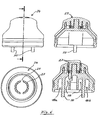
- the dispenser 10 also has a screw cap 10 'which supports the dispenser 10 (here with an applicator 24, cf. Fig. 6 ) and the vent hole of the balance valve 23 dustproof covers to prevent contamination during prolonged storage.
- the filled containers 11a and 11b can be seen, which connect with their dispensing openings 18a and b and filling valves 19 (in particular in the case of liquids) to the dispensing head 15.
- the dispenser 10 shown here is a disposable container, wherein the containers 11a, b are not interchangeable.
- Thread 16 provided (see. Fig. 2 ).
- the dispensing openings 18a, b for the stored substances are embodied in the form of a spout in the exemplary embodiment and permit separate dispensing of the substance stored in the containers 11a, b, so that mixing can take place only subsequently or at the outlet from the applicator 24.
- the outer shell 13 and the dispensing head 15 are designed as reusable containers, after removal of the dispensing head 15 from the outer shell 13 (see latching connection 15a / 13a in the Fig. 2 and 3 ) the containers 11a, b are removed and replaced by "new" containers 11a, 11b.
- the dispensing head 15 or applicator 24 (cf. Fig. 6 ) has at the bottom of spike-like projections 20 which are inserted over the filling valves 19 and press them with locking of the patch on the outer shell 13 dispensing head 15 in the open position.
- the compensation valve 23 shown in the right-hand sectional view is designed in the embodiment as a ball valve and allowed in the position in Fig. 1 the access of air, but prevents in the overhead-use position (see. Fig. 5 ) their exit.
- a version as a gravity-operated ball valve as in Fig. 1 and 5 illustrated, it is also possible to perform the balance valve 23 as a needle valve.
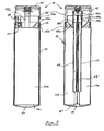
- Fig. 2 the dispensing head 15 is shown in several views, as well as in two sections along the cutting lines AA (broadside) and BB (narrow side) shown above.
- bottom section of Fig. 2 are in the discharge openings 18a, b in contrast to the upper left sectional view in FIG Fig. 1
- No filling valves are provided, since these are not absolutely necessary for the pasty substances, but for liquids.
- a circumferential sealing lip 15b can be seen, which with the upper edge 13b (see. Fig. 3 ) of the outer shell 13 cooperates closely and thus the entire container (except for the balance valve) designed pressure-tight.
- the dispenser 10 is designed as a disposable container, instead of a thread 16 'and a permanent welding of the dispensing head 15 can be performed with the outer shell 13.
- the two (or more) containers 11a, b may also be connected to the outer wall 12 in the one-way embodiment. Likewise, these can via the tube 17 leading to the discharge openings 18a, b (see. Fig. 4 ) be coupled together. These tubes 17 with openings 17 'stabilize the made of a thin-walled material such. B. foil formed container 11 a, b and prevent their collapse in advanced emptying.
- the dispensing of the substances stored in the containers 11a, b takes place via an applicator 24 arranged centrally on the upper side of the dispenser 10.
- applicator 24 has two channels 28 for the separate supply of stored in the containers 11 a, b substances, wherein the output takes place at an annular gap 27 which is interrupted by a connecting web 25.
- This embodiment ensures a separate supply of the substances to the applicator 24 or up to its upper side with a curved applicator surface 29.
- Such an applicator 24 is in the DE 20 2011 002 558 U1 explained in more detail.
- Fig. 1 shows a preferred embodiment of the container (empty or empty) 11a, b in the manner of a foil bag which is welded to sealing seams 11c. These can have any shapes. It is also possible to combine two containers 11a, b via continuous sealing seams 11c into a two-chamber bag, which is then inserted into the outer casing 13. The outer wall 12 ultimately determines the appearance of the dispenser 10 and thus contributes to its distinctness.
- the dispensing head 15 or applicator 24 can have correspondingly diameter-reduced dispensing openings 18a, b, so that a uniform amount of substances is always dispensed when the dispenser is uniformly pressurized.
- the addition of a smaller amount of a substance to a large amount of other substances can then take place. This is useful, for example, when the dispenser 10 is used for multi-component adhesives that require only a small amount of admixing of a hardener.
- the dispenser 10 for cosmetics, in which case a connection of the substances to form, for example, a care substance takes place only when it leaves the dispenser 10. about the embodiment of the applicator 24, as this in Fig. 6 is shown, then a lapse of the emerging from the dispenser 10 cosmetic substances when applied, for example, on the skin or on the lips done.
- the dispenser 10 also has an applicator 24, to which the compensating valve 23 adjoins on the right. This prevents in the overhead position with the downwardly falling sealing ball 23a against a sealing seat, the escape of air from the gap 14 of the dispenser 10, so that the containers 11a, b are pressed together with manual pressurization of the outer wall 12 and the substances are dispensed. After twisting from the overhead position (with the sealing ball 23a falling back within the cage 23b by gravity, see position in FIG Fig.1 On the other hand, an inflow of air through the equalizing valve 23 can take place.
- a modified form of the cover 10 "is shown, namely with a sleeve-like extension, which can be cleaned after use by the Aufsteckkappe (see. DE 20 2008 015 776 the applicant).
- the use of an adjustable system is conceivable in which the cross-section or the size of the dispensing openings 18a, b is variable depending on the amount to be dispensed.
- the dispenser 10 according to the invention thus represents a cost-effective alternative to dispensers 10 with pumping devices, and due to the air-filled gap 14 allows a relatively accurate dosage or a precisely adjustable mixing ratio of the substances delivered due to the absolutely identical pressure conditions, which are arranged on those in the dispenser 10 Container 11a, b act as they are in the same pressure chamber or outer shell 13.
- the equalizing valve 23 (especially together with the filling valves 19 in the containers 11a, b) enables effective filling of the containers 11a, b.
- a compressed air connection can be applied to the equalizing valve 23, so that the intermediate space 14 of the preassembled dispenser 10 can be pressurized with air pressure. Since the outer shell 13 and the dispensing head 15 are sealed, for example, via the sealing lip 15b and the adjacent sealing edge 13b, the air pressure acts on the inserted container 11a, b and pushes them flat together (thus almost vacuum). Then, on the openings 18a, b (see in particular Fig.
- a (commercial) filling head for both substances are placed so that these components can be filled with virtually no air in the container 11 a, b. This is particularly important for the later, uniform delivery from the dispenser 10, but also for materials sensitive to oxidation.
- the filling valves close 19 (or pasty substances by itself) the discharge openings 18a, 18b, until the use or the placement of an applicator with opening on the mandrel-like extensions 20th
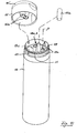
- Fig. 7 shows a further embodiment of the dispenser 10 according to the invention, which comprises two containers 11a, b as a container assembly 11 in the embodiment.
- the containers 11a, b are arranged with their upper region (outlet region 13c) within an outer shell 13 of the dispenser 10, which is formed of a relatively stable plastic material, for example made of PE or PP.
- the downwardly adjoining outer wall 12 against the more stable outer shell 13 is made easier deformable to be well grasped and squeezed by the human hand.
- the deformability of the outer wall 12 is chosen so that it allows a stable installation of the dispenser 10, if not, as here, a curved bottom 10 "is provided.
- the arranged in the interior of the outer wall 12 container 11a, b are also formed of a deformable material, but the material thickness can be very small, in particular in the manner of a film between the containers 11a, b and the outer wall 12 is again the intermediate space 14 which is filled via the above described compensation valve 23 with outside air is (see in Fig. 1 , left sectional view).
- the dispenser 10 also has a lid 10 '(see also FIG Fig. 9 , in the open state), the dust-tight covering the dispenser 10 and the vent hole of the compensation valve 23 to prevent contamination during long storage.
- the filled containers 11a and 11b can be seen, which merge with their discharge openings 18a, b and the discharge area 13c to a dispensing head 15.
- the dispensing openings 18a, b for the stored substances are formed like a spout in the embodiment and allow separate output of the stored in the containers 11a, b substance, so that a mixture can be done later in or on exit from the dispensing head 15.
- the containers 11a, b can be removed from the outer casing 13 (see detent connections 15a / 13a) after removal of the dispensing head 15 and replaced by "new" containers 11a, 11b.
- the dispensing head 15 has at its lower portion notches 15a, which in a corresponding upper groove 13a (see also Fig. 8 ) engage the outer shell 13.
- a second, lower groove 13a is provided at a distance from the outlet region 13c.
- the dispensing head 15 can be pressed even further down, so that the notches then engages in the second, lower groove 13 a (see. Fig. 9 and also Fig. 11 ), whereby tips 16a described below punctures a diffusion seal 17a.
- balancing valve 23 is executed in the embodiment as a ball valve and allowed in the position in Fig. 7 the access of air, but prevents in the overhead-use position (see. Fig. 9 ) their exit.
- the compensation valve 23 it is also possible to carry out the compensation valve 23 as a needle valve.
- An extension of the compensating valve 23 is, similar to the outlet region 13c designed as a "turret", which can serve as a filling valve 19 during filling (see. Fig. 10 ).
- FIG. 8 Top perspective view is shown in the dispensing head 15 inserted from below Umgriffsülse 16 shown in its interior (see. Fig. 7 and 9 ) has two tips 16 a, which serve to pierce or open the diffusion seal 17 when the dispensing head 15 from the position in Fig. 7 (Latches 15a in the upper position) is pushed further down and then locked there in the lower of the grooves 13a.
- the cap-like outer shell 13 is shown as a lower part of the dispensing head 15 from below.
- the boundaries for the discharge openings 18a, b can be seen, as well as the mitangegossene cage 23b of the compensation valve 23 and a sealing lip 13b for tight connection with the outer wall 12 (see. Fig. 7 ).
- the nozzle-shaped discharge openings 18a, b which essentially form the discharge area 13c, and the above-mentioned filling valve 19 can be seen.
- the tubes 17 leading to the discharge openings 18a, b are preferably coupled to one another. These tubes 17 with openings 17 'stabilize the made of a thin-walled material such.
- the dispensing of the substances stored in the containers 11a, b is then effected via a central outlet 18c arranged on the upper side of the dispenser 10 (cf. Fig. 9 ).
- the dispensing head 15 may have correspondingly diameter-reduced dispensing openings 18a, b, so that a uniform amount of substances is dispensed with uniform pressurization of the dispenser 10.
- the addition of a smaller amount of a substance to a large amount of other substances can then take place. This is useful, for example, when the dispenser 10 is used for multi-component adhesives that require only a small amount of admixing of a hardener.
- the dispenser 10 for cosmetics, in which case a connection of the substances to form, for example, a care substance takes place only when it leaves the dispenser 10.
- An applicator can then be used to spread the exiting from the dispenser 10 cosmetic substances during application, for example on the skin or on the lips done.
- Fig. 9 In the overhead position, the downward falling sealing ball 23a against a sealing seat prevents the escape of air from the gap 14 of the dispenser 10, so that the containers 11a, b are pressed together with manual pressure of the outer wall 12 and the substances are discharged.
- an inflow of air through the equalizing valve 23 can take place.
- the dispenser 10 is preferably stored lying after use (with opening of the diffusion seal 17).
- the equalizing valve 23, together with the filling valve 19 in the containers 11a, b, enables the containers 11a, b to be filled effectively, as in FIG Fig. 10 is indicated.
- a compressed air connection can be applied, so that the intermediate space 14 of the preassembled dispenser 10 can be acted upon with air pressure.
- the air pressure on the used, still empty container 11a, b acts and pushes them together flat (thus almost vacuum).
- a (commercial) filling head for both substances can be placed on the adjacent openings 18a, b, so that these components are filled into the containers 11a, b practically without air can.
- Fig. 11 is a modified version in a similar representation as in Fig. 7 shown. Therefore, the same reference numerals apply to similar components in a corresponding manner as the above description.
- an aluminum cap is shown as diffusion seal 17a only above the right discharge opening 18a for clarification with thicker line width.
- the diffusion seals 17a may be very thin, e.g. B. as a coating or vapor deposition (with SiO x ). It is sufficient that the substance-carrying, central outlet region 13c is coated, but also the entire cap-shaped outer casing 13 may be vapor-deposited. As a result, the outer shell 13 can be injection-molded with inexpensive plastics.
- a respective blocking ball 21 made of metal or glass is used (cf. Fig. 10 in the starting position), which are pushed down to the use of the dispenser 10 through the here spike-shaped tips 16a down, so is opened together with the diffusion seal 17a by the dispensing head 15 is pressed (from the left position) down (in here right end position) and then locked in the lower groove 13a.
- Fig. 11 In the left-hand illustration, an intermediate position is shown which corresponds to the respective blocking ball 21 after being filled with respect to the starting position Fig. 10 is pressed by the known filling head into a central constriction. As a result, the container contents are securely sealed for a long storage.
Description
Die Erfindung betrifft einen Spender mit den oberbegrifflichen Merkmalen des Anspruchs 1.The invention relates to a dispenser with the preamble features of claim 1.
Ein solcher Spender ist aus dem Dokument
Neben den bekannten Spendern werden für die Bevorratung der oben genannten Substanzen auch Tuben oder Flaschen verwendet, die über Dosierköpfe oder Dosieröffnungen verfügen, aus denen die Substanz nach direkter Druckbeaufschlagung des Behälters austritt. Nachteilig an diesen Gefäßen ist, dass hier keine vollständige Entleerung der Substanz aus dem Behälter erfolgt, also Restmengen der oft teuren Substanzen verbleiben. Zudem kann über die Ausgabeöffnung Luft in das Innere des Behälters eintreten, was zu einer Oxidation oder zum Verderben der Substanz führen kann. Um dem letztgenannten Problem zu begegnen und um zu verhindern, dass Luft in den substanzbeinhaltenden Behälter eintritt, werden sog. "Bag-in-Bottle"- oder "Bag-in-Bag"-Verpackungen vorgeschlagen. Diese umfassen ein äußeres Behältnis, beispielsweise eine Kunststoffflasche aus einem relativ festen Material oder eine Tube, worin ein mit der Substanz gefüllter zweiter Behälter, in der Regel ein geblasener Beutel angeordnet ist. Solche Spender werden häufig in der Pharmazie für Aerosole verwendet und im sog. Koextrusionsverfahren hergestellt. Zwischen dem äußeren Gefäß und dem davon eingeschlossenen Beutel ist dabei ein Zwischenraum vorgesehen, der mit Luft gefüllt ist. Bei einer Druckbeaufschlagung der äußeren Verpackung wird diese komprimiert und gibt über die in dem Zwischenraum vorhandene Luft den Druck an den Beutel weiter. Aus diesem tritt dann über ein entsprechendes Ausgabeventil die Substanz aus. Dabei kann Luft nachströmen, um die entnommene Substanzmenge vom Volumen her zu ersetzen.In addition to the known dispensers, tubes or bottles are also used for the storage of the above substances, which have dosing heads or metering, from which the substance exits after direct pressurization of the container. A disadvantage of these vessels is that there is no complete emptying of the substance from the container, so residual amounts of the often expensive substances remain. In addition, air can enter the interior of the container via the discharge opening, which can lead to oxidation or spoilage of the substance. In order to address the latter problem and to prevent air from entering the substance-containing container, so-called "bag-in-bottle" or "bag-in-bag" packages are proposed. These comprise an outer container, for example a plastic bottle made of a relatively solid material or a tube, in which a second container filled with the substance, usually a blown bag, is arranged. Such dispensers are frequently used in pharmacy for aerosols and produced in the so-called coextrusion process. Between the outer vessel and the bag enclosed thereby, a gap is provided which is filled with air. When the outer packaging is pressurized, it is compressed and passes the pressure to the bag via the air present in the intermediate space. For this then exits the substance via a corresponding dispensing valve. In this case, air can flow in order to replace the extracted substance volume.
Nachteilig an den genannten Verpackungen ist, dass die meist koextrudierten Innenbehälter nicht diffusionsdicht sind und somit für eine längere Aufbewahrung wenig geeignet sind. Zudem kann nur eine einzige Substanz in der entsprechenden Verpackung aufgenommen werden. Wenn Substanzen bevorratet werden müssen, die erst beim bzw. kurz nach dem Austritt vermischt werden dürfen, da sonst eine vorzeitige Reaktion erfolgt, liegt bislang keine Lösung vor. Dies ist beispielsweise der Fall bei Mehrkomponenten-Klebern oder bestimmten Reinigungsmitteln oder Kosmetika.A disadvantage of the mentioned packaging is that the mostly coextruded inner container are not diffusion-tight and thus are not very suitable for a longer storage. In addition, only a single substance can be included in the appropriate packaging. If substances must be stored, which must be mixed only at or shortly after exiting, otherwise a premature reaction takes place, so far there is no solution. This is the case for example with multi-component adhesives or certain cleaning agents or cosmetics.
Aufgabe der Erfindung ist es daher, einen Spender zur Verfügung zu stellen, der zum einen einfach aufgebaut und befüllbar ist und zudem die getrennte, langfristige Bevorratung von zwei (oder mehr) Substanzen ermöglicht.The object of the invention is therefore to provide a dispenser that is simple to set up and fillable and also allows the separate, long-term storage of two (or more) substances.
Gelöst wird diese Aufgabe durch einen Spender mit den Merkmalen des Anspruches 1. Vorteilhafte Weiterbildungen sind Gegenstand der abhängigen Ansprüche.This object is achieved by a dispenser with the features of claim 1. Advantageous developments are the subject of the dependent claims.
Der erfindungsgemäße Spender für Substanzen eignet sich für die Bevorratung und Ausgabe von Chemikalien, wie den Komponenten von Mehrkomponentenklebern oder von Farben, aber auch für Kosmetika oder pastöse bzw. flüssige Substanzen. Der Spender umfasst dabei eine Außenhülle mit einer verformbaren Außenwand und eine davon umschlossene, ebenfalls verformbare Behälteranordnung. Die Verformbarkeit der Außenwand ist dabei derart eingestellt, dass diese durch einfache Druckbeaufschlagung mit einer Hand oder mehreren Fingern verformbar ist, dabei jedoch eine solche Festigkeit aufweist, die eine stabile Lagerung des Spenders erlaubt. Bei Druckbeaufschlagung der Außenhülle, die ggf. auch über entsprechende Klemmen oder Klammem erfolgen kann, ist vorgesehen, dass die in der inneren Behälteranordnung bevorrateten Substanzen aus dieser austreten. Dies wird dadurch ermöglicht, dass zwischen der Außenwand und der Behälteranordnung ein luftgefüllter Zwischenraum vorgesehen ist und der auf die Außenhülle ausgeübte Druck an beide (oder mehr) Behälter der Behälteranordnung gleichmäßig weitergegeben wird. Um nach der Ausgabe der bevorrateten Substanzen eine Füllung des Zwischenraumes zu gewährleisten, verfügt die Außenhülle über wenigstens ein Einlassventil für Ausgleichsluft. Durch dieses Ausgleichsventil strömt eine entsprechende Luftmenge in den Zwischenraum zwischen verformbarer Außenwand der Außenhülle und die davon umschlossene Behälteranordnung ein. Der vorgeschlagene Spender für Substanzen ist dadurch gekennzeichnet, dass die Behälteranordnung wenigstens zwei Behälter für die getrennte Aufbewahrung flüssiger oder pastöser Substanzen aufweist. Durch diese Ausgestaltung des Spenders wird eine getrennte Bevorratung von Substanzen in einem einzigen Spender möglich. So erlaubt dieser Spender beispielsweise, dass ein Zwei- oder Mehrkomponenten-Klebstoff in einem einzigen Gefäß aufbewahrt wird, aber auch die Bevorratung besonders empfindlicher Kosmetika, wie Haarfärbemittel, die erst beim Austritt aus dem Vorratsbehälter gemischt werden dürfen, um beispielsweise ihre pflegende Wirkung zu entfalten.The substance dispenser according to the invention is suitable for the storage and dispensing of chemicals, such as the components of multicomponent adhesives or of paints, but also for cosmetics or pasty or liquid substances. The dispenser comprises an outer shell with a deformable outer wall and an enclosed, likewise deformable container arrangement. The deformability of the outer wall is set such that it is deformable by simply applying pressure with one hand or several fingers, but it has such a strength that allows stable storage of the dispenser. When pressurizing the outer shell, which may also be done via appropriate terminals or Klammem, it is provided that the stored in the inner container assembly substances emerge from this. This is made possible by providing an air-filled gap between the outer wall and the container assembly and uniformly communicating the pressure exerted on the outer envelope to both (or more) containers of the container assembly. In order to ensure a filling of the gap after the issue of the stored substances, the outer shell has at least one inlet valve for compensation air. Through this compensation valve, a corresponding amount of air flows into the space between the deformable outer wall of the outer shell and the container assembly enclosed by it. The proposed dispenser for substances is characterized in that the container arrangement has at least two containers for the separate storage of liquid or pasty substances. This embodiment of the dispenser allows separate storage of substances in a single dispenser. For example, this dispenser allows a two- or multi-component adhesive to be stored in a single container, as well as the two-component adhesive Stocking of particularly sensitive cosmetics, such as hair dyes, which may only be mixed on leaving the storage container, for example, to develop their nourishing effect.
Um deren Lagerzeit zu erhöhen, wird zudem vorgeschlagen, dass der Austrittsbereich der Behälter eine zumindest weitgehende Diffusionsversiegelung, insbesondere aus Metall, vorzugsweise je eine Aluminiumkappe bzw. Hülse aufweist, die erst bei Benutzung des Spenders vom Abgabekopf, insbesondere mit daran vorgesehenen Spitzen durchstoßen bzw. geöffnet wird. Somit wird der Beutelinhalt insgesamt vor Luftzutritt geschützt, wobei das Öffnen der Versiegelung bevorzugt mit dem Bewegen des Ausgabekopfes von einer Ausgangs- bzw. Lagerstellung in die Benutzungsstellung durch Verrasten erfolgt.In order to increase their storage time, it is additionally proposed that the outlet region of the containers has an at least extensive diffusion seal, in particular made of metal, preferably one aluminum cap or sleeve, which only pierces the dispensing head, in particular with the tips provided, when the dispenser is in use. is opened. Thus, the total bag contents are protected from access of air, wherein the opening of the seal preferably takes place with the movement of the dispensing head from an initial or storage position into the use position by latching.
In einer bevorzugten Weiterbildung ist vorgesehen, dass die in den Behältern bevorrateten Substanzen gleiche oder ähnliche Viskositäten aufweisen. Je nach Ausführung der entsprechenden Mischungsvorrichtung, die zusätzlich am Spender vorgesehen sein kann, besteht somit die Möglichkeit, dass die ausgetragene Menge weitgehend gleich bleibt. Wenn zu einer großen Menge einer ersten Substanz nur eine kleine Menge einer zweiten Substanz, beispielsweise eines Härters abgegeben werden soll, kann dies durch unterschiedliche Querschnitte der Abgabeöffnungen eingestellt werden. Durch diesen Spender wird somit die umständliche Aufbewahrung der zu mischenden Substanzen in getrennten Gebinden vermieden. Zusätzlich kann durch den Spender sichergestellt werden, dass stets gleichbleibende Mischungsverhältnisse der Substanzen aus dem Spender abgegeben werden. Neben der Anordnung von zwei Behältern besteht auch die Möglichkeit, mehr als zwei Behälter, beispielsweise für einen Dreikomponenten-Kleber im Spender anzuordnen.In a preferred embodiment it is provided that the substances stored in the containers have the same or similar viscosities. Depending on the design of the corresponding mixing device, which may additionally be provided on the dispenser, there is thus the possibility that the discharged quantity remains largely the same. If only a small amount of a second substance, for example a hardener, is to be dispensed to a large amount of a first substance, this can be adjusted by different cross sections of the dispensing openings. By this donor thus the cumbersome storage of the substances to be mixed in separate containers is avoided. In addition, it can be ensured by the dispenser that consistently constant mixing ratios of the substances are dispensed from the dispenser. In addition to the arrangement of two containers, it is also possible to arrange more than two containers, for example, for a three-component adhesive in the dispenser.
Als günstig wird angesehen, wenn die Außenhülle aus einem thermoplastischen Kunststoffmaterial gebildet sind. Hierbei bietet sich insbesondere die Verwendung von PE (Polyethylen), PP (Polypropylen) oder PET (Polyethylenterephthalat) an. Die (inneren) Behälter sind vorzugsweise aus Metallfolie oder einer laminierten Mehrschichtfolie (sog. Barrierefolie) gebildet sind, wobei die mit Siegelnähten gefertigten Behälter besonders günstig und diffusionsdicht hergestellt werden können. Je nach Reaktivität der bevorrateten Substanzen kann zusätzlich eine Metallbeschichtung des Kunststoffmaterials vorgesehen werden. Auch unter Frischhaltegesichtspunkten bietet sich eine entsprechende Beschichtung an, da über diese Beschichtung auch eine antibakterielle Wirkung erzielt werden kann.As low is considered when the outer shell are formed of a thermoplastic material. In particular, the use of PE (polyethylene), PP (polypropylene) or PET (polyethylene terephthalate) is suitable. The (inner) containers are preferably formed from metal foil or a laminated multilayer film (so-called barrier film), wherein the containers produced with sealing seams can be produced particularly favorably and diffusion-tight. Depending on the reactivity of the stored substances, a metal coating of the plastic material may additionally be provided. Also under Frischhaltegesichtspunkte offers an appropriate coating, as this coating also an antibacterial effect can be achieved.
Vorteilhaft ist die Ausformung der Behälter als kostengünstige Folienbeutel mit zwei, drei oder auch vier Siegelnähten pro Behälterbeutel. Dabei können die zwei (oder mehr) Beutel in einem Mehrkammerbeutel zusammengefasst sein, beispielsweise über benachbarte Siegelnähte. Hierdurch ist ebenfalls eine getrennte Bevorratung der Substanzen möglich, die Handhabung der Behälteranordnung, z.B. beim Einsetzen in die Außenhülle per Hand oder Maschine jedoch wesentlich vereinfacht. Der Spender (mit eingesetzten und befüllten Beuteln) wird dabei wie folgt betätigt. Die relativ nachgiebige Außenwand der Außenhülle wird mit der Hand oder einer Klemme zusammengedrückt. Dabei entsteht im Innern des Spenders ein Überdruck von z.B. 0,5 bar, der direkt auf die dort angeordneten Beutel wirkt und zwar vollkommen gleichmäßig. Aufgrund des die Behälter umgebenden, luftgefüllten Zwischenraumes erfolgt eine gleichmäßige Beaufschlagung beider Beutel, so dass bei gleichem Austrittsquerschnitt aus diesen eine Ausgabe der jeweils gleichen Menge von Substanz bzw von mehreren Substanz erfolgt, die unabhängig von der Kraft der Druckbeaufschlagung auf die Außenhülle ist.Advantageously, the shape of the container as a cost-effective foil bag with two, three or even four sealing seams per container bag. The two (or more) bags in be summarized a multi-chamber bag, for example, via adjacent sealing seams. As a result, a separate storage of the substances is also possible, the handling of the container assembly, for example, when inserted into the outer shell by hand or machine, however, much easier. The dispenser (with inserted and filled bags) is operated as follows. The relatively flexible outer wall of the outer shell is compressed by hand or a clamp. This creates inside the dispenser, an overpressure of, for example, 0.5 bar, which acts directly on the bag arranged there, and indeed completely uniform. Because of the air-filled intermediate space surrounding the containers, a uniform admission of both bags takes place, so that with the same outlet cross-section, an output of the same quantity of substance or of a plurality of substances takes place, which is independent of the force of the pressurization on the outer casing.
Eine bevorzugte Weiterbildung sieht vor, dass der Spender als Einweggebinde ausgebildet ist. Ein derartiger Spender wird nach der vollständigen Entnahme der darin bevorrateten Substanz entsorgt. Dabei können die Behälter und die Außenwand in wenigstens einem Bereich verbunden sein, insbesondere druckdicht über korrespondierende Dichtlippen. Zur Verbindung kann selbstverständlich auch eine nachträgliche Verschweißung der Behälter und der Außenwand erfolgen. Hierdurch wird verhindert, dass nach teilweiser Entleerung der Behälter diese in dem Gehäuse kollabieren und eine vollständige Entnahme der Substanzen aus den Behältern nicht mehr ermöglichen. Durch die Verbindung zwischen Behälter und Außenwand, wenigstens in einem Teilbereich, bleiben diese bis zur völligen Entleerung aufgerichtet in dem Spender angeordnet. Dies wird auch erzielt, wenn in jedem Behälter ein Röhrchen eingeschweißt ist, dessen freies Ende zudem zur Verbindung mit dem gemeinsamen Abgabekopf dient, sowie für Flüssigkeiten ein Rückschlag- oder Füllventil aufweisen kann.A preferred embodiment provides that the dispenser is designed as a disposable container. Such a dispenser is disposed of after the complete removal of the substance stored therein. The containers and the outer wall can be connected in at least one area, in particular pressure-tight via corresponding sealing lips. For connection, of course, a subsequent welding of the container and the outer wall can be done. This prevents that after partial emptying of the container collapse these in the housing and no longer allow complete removal of the substances from the containers. Due to the connection between the container and the outer wall, at least in a partial area, they remain erected up to complete emptying in the dispenser. This is also achieved if in each container a tube is welded, the free end also serves to connect to the common dispensing head, and liquids may have a check or fill valve.
Zur vereinfachten Entnahme und bedarfsgerechten Mischung der Substanzen wird es als günstig angesehen, wenn ein mit der Außenhülle verbundener Applikator vorgesehen ist. Die Behälter sind dabei mit dem Applikator über Kanäle oder Leitungen verbunden. Der Applikator kann beispielsweise zwei nebeneinanderliegende Ausgabeöffnungen oder entsprechend zwei oder mehr konzentrisch angeordnete Ringspalte aufweisen, aus denen die Substanzen getrennt ausgeleitet werden und sich erst beim Austreten aus dem Applikator mischen.For simplified removal and need-based mixing of the substances, it is considered favorable if an applicator connected to the outer shell is provided. The containers are connected to the applicator via channels or lines. The applicator can, for example, have two juxtaposed dispensing openings or correspondingly two or more concentrically arranged annular gaps, from which the substances are discharged separately and do not mix until they emerge from the applicator.
Vorteilhaft ist weiterhin, dass der Spender als Mehrweggebinde ausgebildet sein kann, also austauschbare oder wiederbefüllbare Behälter in seinem Inneren aufweist. Um die entleerten Behälter entnehmen zu können bzw. um hier eine Wiederbefüllung durchführen zu können, weist der Spender einen abnehmbaren Abgabekopf auf. Dieser ist insbesondere als Schraub- oder Steckverschluss ausgebildet bzw. mit der Außenhülle über eine entsprechende Schnappverbindung verbunden. Neben einem abnehmbaren Verschluss bzw. Abgabekopf besteht auch die Möglichkeit, dass die Außenhülle, beispielsweise im Bodenbereich, eine Klappe oder Deckel aufweist und so den Zugang zu den im Innern angeordneten Behältern zulässt. Der an dem Spender vorgesehene Verschluss ist in günstiger Weise zugleich als Applikator ausgebildet und bietet somit die obigen Vorteile.A further advantage is that the dispenser can be designed as a reusable container, so has interchangeable or refillable container in its interior. In order to be able to remove the emptied containers or to be able to carry out a refilling here, the dispenser has a removable dispensing head. This is designed in particular as a screw or plug-in closure or connected to the outer shell via a corresponding snap connection. In addition to a removable closure or dispensing head there is also the possibility that the outer shell, for example in the bottom area, has a flap or lid and thus allows access to the containers arranged in the interior. The closure provided on the dispenser is also advantageously designed as an applicator and thus offers the above advantages.
Als Ausgleich für die entnommene Substanzmenge strömt beim Spender Luft in den Zwischenraum zwischen Außenwand und Behälter ein. Um hierbei eine schnelle Wiederbefüllung des Zwischenraumes mit Außenluft zu ermöglichen, ist das Einlassventil als in der Außenwand oder im Verschluss angeordnetes Ventil ausgebildet. Als Ventil bietet sich hierbei insbesondere die Anordnung eines sog. Kugel- oder Nadelventils an. Dieses wird durch den in dem Behälter nach der Substanzentnahme herrschenden Unterdruck oder bevorzugt durch Schwerkraft geöffnet, indem der Spender gegenüber der bevorzugt Überkopf-Position in Gebrauchsstellung wieder aufrecht gestellt wird. Das Ventil kann hier bei der Formgebung des Abgabekopfes mit ein- oder angeformt werden, insbesondere in Art eines Käfigs zur Führung einer (kleinen) Kugel. Diese Bauweise ist von eigenständiger, erfinderischer Bedeutung, da hierdurch mehrere Funktionen erzielt werden. So erlaubt ein solches Kugel- oder Nadelventil in der aufrechten Stellung des Spenders und damit Offenposition die langfristige Lagerung ohne große Druckschwankungen (z. B. durch Temperaturänderungen) und damit auch den Transport mit Flugzeugen. Bei der Befüllung der Behälter kann an das Ausgleichventil Druckluft angelegt werden, um die Folienbeutel vor dem Befüllen mit der Substanz flach zusammen zu drücken, also zu entlüften. In der Gebrauchstellung (Überkopfposition) erlaubt die gravitationsbetätigte Kugel zusammen mit einem Dichtsitz eine sichere Abdichtung und damit einfache Druckbeaufschlagung.As compensation for the amount of substance removed, air flows into the space between the outer wall and the container at the dispenser. In order to allow rapid refilling of the intermediate space with outside air, the inlet valve is designed as a valve arranged in the outer wall or in the closure. In particular, the arrangement of a so-called ball or needle valve offers itself here as a valve. This is opened by the pressure prevailing in the container after the substance removal negative pressure or preferably by gravity by the dispenser is placed against the preferred overhead position in the use position upright again. The valve can here with the shaping of the dispensing head with or be formed, in particular in the manner of a cage for guiding a (small) ball. This design is of independent, inventive importance, as this several functions are achieved. Thus, such a ball or needle valve in the upright position of the dispenser and thus open position allows long-term storage without large pressure fluctuations (eg by temperature changes) and thus also the transport by aircraft. When filling the containers, compressed air can be applied to the equalizing valve in order to compress the foil bags flat before filling with the substance, ie to deaerate them. In the use position (overhead position), the gravity-actuated ball together with a sealing seat allows a secure seal and thus easy pressurization.
Zudem kann der Bodenbereich der Außenwand eine abgerundete Form aufweisen, so dass der Spender "Überkopf" stehend oder liegend aufbewahrt wird, wobei ein "Auslaufen" unterbunden wird. So kann der Spender bei geöffnetem Klappdeckel nicht "Überkopf" gestellt werden, was ein unbeabsichtigtes "Auslaufen" ebenfalls unterbindet. Als Belüftungsventil bietet sich hier ein sog. Kugelventil an.In addition, the bottom portion of the outer wall may have a rounded shape so that the dispenser is stored "overhead" standing or lying, preventing "leakage". Thus, the dispenser can not be placed "overhead" with the hinged lid open, which also prevents an unintentional "leakage". As a vent valve here is a so-called. Ball valve on.
Weitere Vorteile, Merkmale und Besonderheiten der Erfindung ergeben sich aus der nachfolgenden Beschreibung bevorzugter Ausführungsformen der Erfindung anhand der schematischen Zeichnungen. Hierbei zeigt:
- Fig. 1
- eine schematische Darstellung eines erfindungsgemäßen Spenders in Perspektivdarstellung, sowie in zwei Längsschnitten (um 90° versetzt);
- Fig. 2
- mehrere Ansichten eines am Spender vorgesehenen Abgabekopfes;
- Fig. 3
- zwei Ansichten einer (ovalen) Außenhülle des Spenders;
- Fig. 4
- mehrere Ansichten eines (ungefüllten) Behälters in Beutelform;
- Fig. 5
- einen Spender in Überkopfposition als bevorzugter Gebrauchstellung;
- Fig. 6
- mehrere Ansichten eines bevorzugt eingesetzten Applikators;
- Fig. 7
- eine schematische Darstellung eines erfindungsgemäßen Spenders in zwei Längsschnittdarstellungen (um 90° gegeneinander versetzt);
- Fig. 8
- mehrere Ansichten eines Innenteils (sog. Umgriffshülse) des Abgabekopfes und zwei Perspektivansichten der Außenhülle, die unterhalb des Abgabekopfes angeordnet ist;
- Fig. 9
- einen Spender in Überkopfposition als bevorzugter Gebrauchstellung;
- Fig. 10
- eine Explosionsansicht des Spenders in Befüllstellung; und
- Fig. 11
- eine abgewandelte Ausführung, ähnlich zur Darstellung in
Fig. 7 .
- Fig. 1
- a schematic representation of a dispenser according to the invention in a perspective view, as well as in two longitudinal sections (offset by 90 °);
- Fig. 2
- a plurality of views of a donor provided on the dispensing head;
- Fig. 3
- two views of an (oval) outer shell of the donor;
- Fig. 4
- several views of an (unfilled) container in bag form;
- Fig. 5
- a donor in overhead position as a preferred use position;
- Fig. 6
- several views of a preferably used applicator;
- Fig. 7
- a schematic representation of a dispenser according to the invention in two longitudinal sectional views (offset by 90 ° to each other);
- Fig. 8
- several views of an inner part (so-called Umgriffshülse) of the dispensing head and two perspective views of the outer shell, which is arranged below the dispensing head;
- Fig. 9
- a donor in overhead position as a preferred use position;
- Fig. 10
- an exploded view of the dispenser in filling position; and
- Fig. 11
- a modified embodiment, similar to the representation in
Fig. 7 ,
In der linken Schnittdarstellung (mittig durch die Schmalseite des Spenders) sind die befüllten Behälter 11a und 11b erkennbar, die mit ihren Abgabeöffnungen 18a und b sowie Füllventilen 19 (insbesondere bei Flüssigkeiten) an den Abgabekopf 15 anschließen. Bei dem hier dargestellten Spender 10 handelt es sich um ein Einweggebinde, wobei die Behälter 11a, b nicht austauschbar sind. Zum Anbringen des Deckels 10' ist hier ein Gewinde 16 vorgesehen (vgl.
Das in der rechten Schnittdarstellung gezeigte Ausgleichsventil 23 ist im Ausführungsbeispiel als Kugelventil ausgeführt und erlaubt in der Stellung in
In
Dieser in
Wie bereits beschrieben, befindet sich zwischen der Außenwand 12 des Spenders 10 und den Behältern 11a,b ein Zwischenraum 14, der mit Luft gefüllt ist. Dieser Zwischenraum 14 gewährleistet die gleichmäßige Verteilung des auf die Außenwand 12 ausgeübten Druckes, der zur Entnahme der Substanzen aus den Behältern 11a,b nötig ist. Nach Entnahme einer bestimmten Menge einer Substanz (in der Gebrauchs- bzw. Überkopfstellung nach
In
Neben der hier dargestellten Anordnung von zwei Behältern 11a, b mit gleichem Volumen besteht auch die Möglichkeit, dass die Behälter 11a, b unterschiedliche Volumina aufweisen. Zudem kann der Abgabekopf 15 bzw. Applikator 24 entsprechend durchmesserverringerte Ausgabeöffnungen 18a,b aufweisen, so dass bei gleichmäßiger Druckbeaufschlagung des Spenders 10 stets eine im Verhältnis gleiche Menge an Substanzen ausgegeben wird. Bei dieser Ausgestaltung des Spenders 10 kann dann beispielsweise die Zumischung einer geringeren Menge einer Substanz zu einer großen Menge weiterer Substanzen erfolgen. Dies bietet sich beispielsweise an, wenn der Spender 10 für Mehrkomponenten-Klebstoffe verwendet wird, die nur eine geringe Beimischung eines Härters benötigen. Neben der Verwendung mit Klebstoffen besteht selbstverständlich auch die Möglichkeit, den Spender 10 für Kosmetika einzusetzen, wobei hier eine Verbindung der Substanzen zur Bildung beispielsweise einer Pflegesubstanz erst beim Austreten aus dem Spender 10 erfolgt. Über die Ausgestaltung des Applikators 24, wie dieser in
Gemäss
Neben der Ausgestaltung des Applikators 24 mit definiertem Durchmesser der Ausgabeöffnungen 18a, b ist auch die Verwendung eines einstellbaren Systems denkbar, bei dem der Querschnitt bzw. die Größe der Ausgabeöffnungen 18a,b in Abhängigkeit von der zu spendenden Menge veränderbar ist. Der erfindungsgemäße Spender 10 stellt somit eine kostengünstige Alternative zu Spendern 10 mit Pumpvorrichtungen dar, und ermöglicht aufgrund des luftgefüllten Zwischenraumes 14 eine relativ genaue Dosierung bzw. ein genau einstellbares Mischungsverhältnis der abgegebenen Substanzen aufgrund der absolut identischen Druckverhältnisse, die auf die in dem Spender 10 angeordneten Behälter 11a, b einwirken, da sich diese in der gleichen Druckkammer bzw. Außenhülle 13 befinden.In addition to the configuration of the
Insbesondere ermöglicht das Ausgleichsventil 23 (vor allem zusammen mit den Füllventilen 19 in den Behältern 11a,b) ein effektives Befüllen der Behälter 11a,b. So kann an das Ausgleichsventil 23 ein Druckluftanschluss angelegt werden, so dass der Zwischenraum 14 des vormontierten Spenders 10 mit Luftdruck beaufschlagt werden kann. Da die Außenhülle 13 und der Abgabekopf 15 z.B. über die Dichtlippe 15b und den anliegenden Dichtrand 13b abgedichtet sind, wirkt der Luftdruck auf die eingesetzten Behälter 11a, b ein und drückt diese flach zusammen (damit nahezu luftleer). Dann kann auf die Öffnungen 18a,b (vgl. insbesondere
In der rechten Schnittdarstellung (mittig durch den hier zylindrisch geformten Spender 10) sind die befüllten Behälter 11a und 11b erkennbar, die mit ihren Abgabeöffnungen 18a, b und dem Austrittsbereich 13c zu einem Abgabekopf 15 übergehen. Die Ausgabeöffnungen 18a, b für die bevorrateten Substanzen sind im Ausführungsbeispiel tüllenartig ausgebildet und erlauben eine getrennte Ausgabe der in den Behältern 11a,b bevorrateten Substanz, so dass eine Mischung erst nachträglich im oder beim Austritt aus dem Abgabekopf 15 erfolgen kann. Wenn die Außenhülle 13 und der Abgabekopf 15 als Mehrweggebinde ausgelegt sind, können nach Abnehmen des Abgabekopfs 15 von der Außenhülle 13 (vgl. Rastverbindungen 15a/13a) die Behälter 11a,b entnommen werden und durch "neue" Behälter 11a, 11b ersetzt werden. Der Abgabekopf 15 weist an seinem unteren Bereich Rasten 15a auf, die in eine entsprechende, obere Nut 13a (vgl. auch
Das in der linken Schnittdarstellung von
In
In der mittleren Perspektivansicht von
Wie bereits beschrieben, befindet sich zwischen der Außenwand 12 des Spenders 10 und den Behältern 11a,b ein Zwischenraum 14, der mit Luft gefüllt ist. Dieser Zwischenraum 14 gewährleistet die gleichmäßige Verteilung des auf die Außenwand 12 ausgeübten Druckes, der zur Entnahme der Substanzen aus den Behältern 11a,b nötig ist. Nach Entnahme einer bestimmten Menge einer Substanz (in der Gebrauchs- bzw. Überkopfstellung nach
Neben der hier dargestellten Anordnung von zwei Behältern 11a, b mit gleichem Volumen besteht auch die Möglichkeit, dass die Behälter 11a,b unterschiedliche Volumina aufweisen. Zudem kann der Abgabekopf 15 entsprechend durchmesserverringerte Ausgabeöffnungen 18a, b aufweisen, so dass bei gleichmäßiger Druckbeaufschlagung des Spenders 10 eine im Verhältnis entsprechende Menge an Substanzen ausgegeben wird. Bei dieser Ausgestaltung des Spenders 10 kann dann beispielsweise die Zumischung einer geringeren Menge einer Substanz zu einer großen Menge weiterer Substanzen erfolgen. Dies bietet sich beispielsweise an, wenn der Spender 10 für Mehrkomponenten-Klebstoffe verwendet wird, die nur eine geringe Beimischung eines Härters benötigen. Neben der Verwendung mit Klebstoffen besteht selbstverständlich auch die Möglichkeit, den Spender 10 für Kosmetika einzusetzen, wobei hier eine Verbindung der Substanzen zur Bildung beispielsweise einer Pflegesubstanz erst beim Austreten aus dem Spender 10 erfolgt. Mit einem Applikator kann dann ein Verstreichen der aus dem Spender 10 austretenden kosmetischen Substanzen beim Auftragen, beispielsweise auf der Haut oder auf den Lippen, erfolgen.In addition to the arrangement shown here of two
Gemäss
Zudem ermöglicht das Ausgleichsventil 23 zusammen mit dem Füllventil 19 in den Behältern 11a,b ein effektives Befüllen der Behälter 11a,b, wie in
In
Wie vorstehend erwähnt, ist innerhalb der Abgabeöffnungen 18a, 18b in besonders bevorzugter Ausführung je eine Sperrkugel 21 aus Metall oder Glas eingesetzt (vgl.
- 10 = Spender (mit Deckel 10', Boden 10")10 = dispenser (with lid 10 ', bottom 10 ")
-
11a,b = Behälter (mit Siegelnaht 11c)11a, b = container (with sealed
seam 11c) - 12 = Außenwand12 = outer wall
-
13 = Außenhülle (mit Nuten 13a)13 = outer shell (with
grooves 13a) - 13b = Dichtlippe bzw. Rand13b = sealing lip or edge
- 13c = Austrittsbereich13c = exit area
- 14 = Zwischenraum14 = intermediate space
-
15 = Abgabekopf (mit Rasten 15a, Dichtlippe 15b)15 = dispensing head (with
detents 15a, sealing lip 15b) -
16 = Umgriffshülse (mit Spitzen 16a, Gewinde 16')16 = grip sleeve (with
tips 16a, thread 16 ') - 17 = Röhrchen (mit Öffnungen 17')17 = tubes (with openings 17 ')
- 17a = Diffusionsversiegelung17a = diffusion seal
- 18a,b = Ausgabeöffnung18a, b = discharge opening
- 18c = Zentral-Auslass18c = central outlet
- 19 = Füllventil19 = filling valve
- 20 = Fortsatz20 = extension
- 21 = Sperrkugel (mit Radialstegen 21')21 = blocking ball (with radial webs 21 ')
- 23 = Ausgleichsventil23 = equalizing valve
- 24 = Applikator24 = applicator
- 25 = Verbindungssteg25 = connecting bridge
- 27 = Ringspalt27 = annular gap
- 28 = Kanäle28 = channels
- 29 = Applikationsfläche29 = application area
Claims (15)
- Dispenser for substances, comprising an outer sleeve (13) with a deformable outer wall (12), which encompasses a deformable container arrangement (11), and at least one balancing valve (23) for balancing air, with an air-filled space (14) being provided between the outer wall (12) and the container arrangement and the delivery of the substances taking place after pressurization of the outer sleeve (13), with the container arrangement having at least two containers (11a, b) for the separated storage of liquid or pasty substances and the containers (11a, b) and a joint dispenser head for the substance delivery (15) being connected pressure proof in at least one area,
characterized in that
the containers (11a, b) have self-closing filling valves (19) which can be pressed upon when the containers are filled with substances, or in that an outlet area (13c) of the container arrangement (11) has a diffusion sealing (17a), in particular of metal, which is pushed through or opened, respectively, by the dispenser head (15) before the dispenser (10) is used, or in that in release openings (18a, 18b) of the dispenser arrangement (11), one locking ball (21) is inserted into each opening, which ball is pressed in a sealing manner when being in its central position, as well as passable in its outlet and filling position, respectively, and use position of the dispenser (10), in particular by means of radial bars (21'). - The dispenser according to claim 1, characterized in that the containers (11a, b) are configured as foil bags, in particular with plural sealed seams (11c) and that preferably, the containers (11a, b) are combined as multi-chamber bags.
- The dispenser according to one of the preceding claims, characterized in that the dispenser (10) is configured as a disposable bundle and that in particular, an applicator (24) is provided which is connected with the outer sleeve (13), with the container (11a, b) being connected with the applicator (24) via channels (28) for the separated delivery of the substances.
- The dispenser according to one of the preceding claims, characterized in that the containers (11a, b) each comprise a small tube (17), preferably with openings (17').
- The dispenser according to one of the preceding claims, characterized in that the balancing valve (23) is configured as a valve that is arranged in the outer wall (12) or in the dispenser head (15), in particular as a ball valve or needle valve.
- The dispenser according to claim 5, characterized in that
a gravity-actuated sealing ball (23a) is guided into a cage (23b). - The dispenser according to one of the preceding claims, characterized in that
for filling the containers (11a, b), the balancing valve (23) is pressurized, in particular with compressed air for venting the containers (11a, b). - The dispenser according to claim 1, characterized in that
tips (16a) for pushing through or opening, respectively, the diffusion sealing are provided. - The dispenser according to claim 1 or 8, characterized in that the diffusion sealing (17a) is configured as an attachable aluminum cap or sleeve, respectively.
- The dispenser according to one of the preceding claims, characterized in that an encompassing sleeve (16) is inserted centrally in the dispenser head (15), which sleeve is configured suitably with respect to the outlet openings (18a, b) of the container arrangement (11).
- The dispenser according to claim 10, characterized in that two chamfered sleeves or tips (16) are provided within the encompassing sleeve (16a).
- The dispenser according to one of the preceding claims, characterized in that the dispenser (10) has a lid (10'), in particular with a flap mechanism.
- The dispenser according to claim 12, characterized in that the lid (10') closes an outlet opening (18c) in a sealing manner, which opening is adjacent to a mixing element, in particular a static mixer.
- The dispenser according to one of the preceding claims, characterized in that the bottom (10") has a shape which prohibits the dispenser (10) to be erected, particularly due to its rounded shape.
- The dispenser according to one of the preceding claims, characterized in that the outer wall (12) and the outer sleeve (13) are connected via a ring-shaped circumferential sealing lip (13b).
Applications Claiming Priority (3)
| Application Number | Priority Date | Filing Date | Title |
|---|---|---|---|
| DE201420001720 DE202014001720U1 (en) | 2014-02-27 | 2014-02-27 | donor |
| DE202014009449.7U DE202014009449U1 (en) | 2014-11-29 | 2014-11-29 | donor |
| PCT/EP2015/000458 WO2015128092A1 (en) | 2014-02-27 | 2015-02-27 | Dispenser |
Publications (2)
| Publication Number | Publication Date |
|---|---|
| EP3110562A1 EP3110562A1 (en) | 2017-01-04 |
| EP3110562B1 true EP3110562B1 (en) | 2018-11-07 |
Family
ID=52737047
Family Applications (1)
| Application Number | Title | Priority Date | Filing Date |
|---|---|---|---|
| EP15712042.9A Active EP3110562B1 (en) | 2014-02-27 | 2015-02-27 | Dispenser |
Country Status (5)
| Country | Link |
|---|---|
| US (2) | US10661290B2 (en) |
| EP (1) | EP3110562B1 (en) |
| CN (2) | CN110304351B (en) |
| DE (1) | DE202014001720U1 (en) |
| WO (1) | WO2015128092A1 (en) |
Families Citing this family (15)
| Publication number | Priority date | Publication date | Assignee | Title |
|---|---|---|---|---|
| US9751021B2 (en) * | 2015-10-22 | 2017-09-05 | Universal City Studios Llc | Water ride flotation device dispenser |
| FR3047646B1 (en) * | 2016-02-12 | 2021-06-25 | Aptar France Sas | FLUID PRODUCT DISPENSER. |
| DE102016104190A1 (en) * | 2016-03-08 | 2017-09-14 | Gerhard Brugger | Dispenser for the dispensing of liquid or pasty substances |
| CN105686309B (en) * | 2016-04-20 | 2018-10-30 | 京东方科技集团股份有限公司 | A kind of pressing bottle |
| US10667592B2 (en) * | 2016-06-18 | 2020-06-02 | Karen Gayton | Integrated at least two component system and method |
| FR3061842B1 (en) * | 2017-01-16 | 2019-04-05 | L'oreal | COSMETIC PRODUCT APPLICATION DEVICE, NECESSARY AND RESERVOIR |
| JP6922523B2 (en) * | 2017-07-28 | 2021-08-18 | コクヨ株式会社 | Applied product |
| US20190193892A1 (en) * | 2017-12-21 | 2019-06-27 | Karen Gayton | Integrated at least two component system and method |
| CN108328116A (en) * | 2018-03-30 | 2018-07-27 | 广州美泰塑料包装有限公司 | A kind of dual-color ice cream casing |
| JP7235271B2 (en) * | 2018-05-14 | 2023-03-08 | 大成化工株式会社 | discharge container |
| DE102018112442A1 (en) * | 2018-05-24 | 2019-11-28 | Gerhard Brugger | Dosing dispenser for dosing of at least one recorded in a receiving compartment material component |
| CN109178670B (en) * | 2018-12-06 | 2019-04-19 | 烟台五神生物科技有限公司 | A kind of container saving oxidizable mixing content |
| CN109703909A (en) * | 2019-01-13 | 2019-05-03 | 中山市华宝勒生活用品实业有限公司 | A kind of inflating lid and its container of quick tonifying Qi |
| EP4234428A3 (en) * | 2021-05-25 | 2023-10-18 | MC2 Therapeutics A/S | Dispenser |
| KR20230021916A (en) * | 2021-08-06 | 2023-02-14 | 펌텍코리아 (주) | Liquid content discharge container |
Family Cites Families (114)
| Publication number | Priority date | Publication date | Assignee | Title |
|---|---|---|---|---|
| US2367883A (en) * | 1942-09-21 | 1945-01-23 | Frankfort Distilleries Inc | Bottle closure |
| GB676094A (en) | 1946-03-22 | 1952-07-23 | Prel Inc | Dispensing device |
| US2608320A (en) * | 1947-03-31 | 1952-08-26 | Jr Joseph R Harrison | Pump type dispenser with cartridge having flexible and rigid portions |
| FR1314002A (en) * | 1961-11-24 | 1963-01-04 | Method and device for dispensing a non-compacted substance | |
| BE639762A (en) * | 1962-11-16 | |||
| US3269389A (en) * | 1963-03-11 | 1966-08-30 | Bernard L Meurer | Compartmental dispensing container for nose and throat preparations |
| US3240399A (en) * | 1963-08-14 | 1966-03-15 | Ned W Frandeen | Dispensing receptacle |
| US3306500A (en) * | 1965-11-12 | 1967-02-28 | Alfred D Williams | Squeeze tube dispenser |
| US3399811A (en) * | 1967-01-27 | 1968-09-03 | Owens Illinois Inc | Liquid pourout fitment |
| US3709437A (en) * | 1968-09-23 | 1973-01-09 | Hershel Earl Wright | Method and device for producing foam |
| US3874428A (en) * | 1973-08-08 | 1975-04-01 | Charles R Golay | Remote fill system for L-P gas cylinder |
| US4020978A (en) * | 1975-08-15 | 1977-05-03 | Harry Szczepanski | Manually-operated dispenser |
| GB1576810A (en) * | 1976-02-17 | 1980-10-15 | Metal Box Co Ltd | Valve assemblies for aerosol containers |
| US4091849A (en) * | 1977-02-22 | 1978-05-30 | Terminator Products, Inc. | Safe tank filling apparatus |
| US4159790A (en) * | 1977-12-19 | 1979-07-03 | Bailey Vincent R | Dispensing container |
| US4322020A (en) * | 1978-05-02 | 1982-03-30 | Raymond Stone | Invertible pump sprayer |
| US4300555A (en) * | 1979-12-17 | 1981-11-17 | Louis Kopito | Product, composition, and process for anorectal prophylactic and/or therapeutic care |
| US4363336A (en) * | 1981-04-07 | 1982-12-14 | Vending Components, Inc. | Keg-tapping structure |
| US4469250A (en) * | 1982-02-25 | 1984-09-04 | Nick Sekich, Jr. | Squeezable dispensing apparatus and method of operation |
| DE3239784A1 (en) * | 1982-10-27 | 1984-05-03 | Wella Ag, 6100 Darmstadt | DOUBLE TANK FOR TWO SEPARATE LIQUIDS |
| US4687663B1 (en) | 1983-03-01 | 1997-10-07 | Chesebrough Ponds Usa Co | Dental preparation article and method for storage and delivery thereof |
| US4488572A (en) * | 1983-07-18 | 1984-12-18 | Grundy Dispense Systems, Inc. | Apparatus for retaining a valve body in engagement with the valve neck of a pressurized container |
| US4715414A (en) * | 1985-02-11 | 1987-12-29 | Grundy Dispense Systems, Inc. | Concentric well-type extractor tube for filling containers with pressurized fluid |
| JPS62251355A (en) * | 1986-04-10 | 1987-11-02 | 北村 行三 | Switching mechanism of mouth section of liquid container |
| US4760937A (en) * | 1986-06-16 | 1988-08-02 | Evezich Paul D | Squeezable device for ejecting retained materials |
| FR2612571B1 (en) * | 1987-03-17 | 1992-03-06 | Valois | PUMP DISPENSER FOR SMALL PRECISE DOSES OF FLUID PRODUCT |
| DE3720265A1 (en) | 1987-06-19 | 1988-12-29 | Hartmann As Brdr | METHOD FOR PRODUCING COLORED EGG PACKAGING, DEVICE FOR CARRYING OUT SUCH A METHOD AND EGG PACKAGING PRODUCED BY SUCH A PROCESS |
| US5102010A (en) * | 1988-02-16 | 1992-04-07 | Now Technologies, Inc. | Container and dispensing system for liquid chemicals |
| US4838457A (en) * | 1988-05-09 | 1989-06-13 | Swahl James C | Lotion blending and dispensing unit |
| DE8810049U1 (en) * | 1988-08-06 | 1989-01-05 | Hansa Gmbh Kunststoffverarbeitung Und Werkzeugbau, 3354 Dassel, De | |
| US4938421A (en) * | 1988-12-23 | 1990-07-03 | Shop-Vac Corporation | Cleaning liquid mixer for a water line, particularly for a surface cleaner |
| US4993594A (en) * | 1989-09-27 | 1991-02-19 | Piper Becker | Multi-constituent mixing and metering dispenser |
| ES2079646T3 (en) * | 1990-02-22 | 1996-01-16 | Procter & Gamble | BOTTLE FLUID DISTRIBUTOR WITH COMPRESSIBLE BAG WITH MEANS TO RESIST CRUSHING OF THE BAG INSERTED WITHIN IT. |
| US5108007A (en) * | 1990-03-09 | 1992-04-28 | Allergan, Inc. | Valve controlled squeezable fluid dispenser |
| FR2662672B1 (en) * | 1990-05-31 | 1992-08-21 | Aerosols & Bouchage | MIXTURE DISPENSER. |
| DE9013730U1 (en) * | 1990-10-02 | 1992-02-06 | Hago-Chemotechnik Gmbh & Co. Kg, 8000 Muenchen, De | |
| JPH04161160A (en) | 1990-10-26 | 1992-06-04 | Mercian Corp | Formalin fumigating/sterilizing device |
| US5273191A (en) * | 1991-08-20 | 1993-12-28 | Philip Meshberg | Dispensing head for a squeeze dispenser |
| US6305577B1 (en) * | 1991-09-13 | 2001-10-23 | Owens-Illinois Closure Inc. | Squeeze dispenser package for viscous products |
| US5305920A (en) * | 1991-11-20 | 1994-04-26 | The Procter & Gamble Company | Bag-in-bottle package with reusable resilient squeeze bottle and disposable inner receptacle which inverts upon emptying without attachment near its midpoint to squeeze bottle |
| JPH07502239A (en) * | 1991-12-18 | 1995-03-09 | ザ、プロクター、エンド、ギャンブル、カンパニー | Package with replaceable inner container with large integrally molded attachment area |
| CA2097866A1 (en) * | 1992-06-11 | 1993-12-12 | Howard Norman Reiboldt | Method and apparatus for assembling a thin film beam spring vent valve |
| DE4219857A1 (en) * | 1992-06-17 | 1993-12-23 | Perfect Ventil Gmbh | Deformable container for dispensing liquid |
| US5398846A (en) * | 1993-08-20 | 1995-03-21 | S. C. Johnson & Son, Inc. | Assembly for simultaneous dispensing of multiple fluids |
| US5988415A (en) * | 1994-02-23 | 1999-11-23 | Paul And Sara Garbarini 1989 Family Trust | Bottle flow controller |
| JPH08164954A (en) * | 1994-12-15 | 1996-06-25 | Yoshida Kogyo Kk <Ykk> | Tube container |
| US5573043A (en) * | 1994-12-23 | 1996-11-12 | Stoffel Seals Corporation | Closure cup for a pressure dispenser |
| US5586589A (en) * | 1995-05-19 | 1996-12-24 | Monsanto Company | Refillable closed container system |
| US6042850A (en) * | 1995-08-21 | 2000-03-28 | Ida; Frank | Nursing bottle utilizing air pressure to expel air from disposable liners and methods using same for feeding an infant |
| US5752626A (en) * | 1995-09-08 | 1998-05-19 | Owens-Illinois Closure Inc. | Simulataneous pump dispenser |
| GB9526386D0 (en) * | 1995-12-22 | 1996-02-21 | Diversey Equipment Technologie | Dispenser |
| US6241125B1 (en) * | 1996-10-24 | 2001-06-05 | Kenneth H. Jacobsen | System and kit accessories for dispensing reactive two component materials |
| US5752636A (en) | 1996-11-06 | 1998-05-19 | Manley; Christopher D. | Truck bed extender |
| US5832965A (en) * | 1997-01-02 | 1998-11-10 | Fasse; James H. | Aerosol container filling apparatus |
| NL1005189C2 (en) * | 1997-02-05 | 1998-08-06 | Airspray Int Bv | Dispensing assembly for dispensing two liquid components. |
| US6736288B1 (en) * | 2000-10-26 | 2004-05-18 | Ronald D. Green | Multi-valve delivery system |
| FR2776633B1 (en) * | 1998-03-26 | 2000-06-09 | Valois Sa | AIRLESS DISTRIBUTION DEVICE |
| US6302607B1 (en) * | 1998-11-20 | 2001-10-16 | The Procter & Gamble Company | Fluid applicators |
| RU2161282C1 (en) * | 1999-05-13 | 2000-12-27 | Багнюков Сергей Анатольевич | Gas cylinder and method for charging it |
| NL1012474C2 (en) * | 1999-06-29 | 2001-01-02 | Heineken Tech Services | Flexible container made of foil material and filling method for filling such a container with a liquid substance. |
| US6216915B1 (en) * | 1999-08-24 | 2001-04-17 | Owens-Brockway Plastic Products Inc. | Dual chamber package |
| US20010025859A1 (en) * | 2000-02-17 | 2001-10-04 | Charles Dumont | Mixing and dispensing container having removably attachable supply vessels |
| DE20108495U1 (en) * | 2001-05-18 | 2001-08-09 | Gobbers Walter | Spray can |
| JP4672906B2 (en) * | 2001-05-30 | 2011-04-20 | 東洋エアゾール工業株式会社 | Aerosol valve for high-speed filling |
| FR2831142B1 (en) * | 2001-10-22 | 2004-02-20 | Airlessystems | FLUID PRODUCT DISPENSER |
| FR2835813B1 (en) * | 2002-02-13 | 2004-05-07 | Lablabo | DEVICE FOR PACKAGING AND DISPENSING MULTIPLE FLUIDS COMPRISING AT LEAST TWO PUMPS |
| WO2003092905A1 (en) * | 2002-05-04 | 2003-11-13 | Gerhard Brugger | Dosage dispenser |
| DE20207029U1 (en) * | 2002-05-04 | 2002-08-08 | Brugger Anton | Dispensers |
| US20040065678A1 (en) * | 2002-05-21 | 2004-04-08 | Dieter Gobbers | Spraying apparatus for introducing substances into the body or applying substances onto the body |
| US7036685B1 (en) * | 2002-06-17 | 2006-05-02 | Green Ronald D | Multi-valve delivery system |
| US7967220B2 (en) * | 2002-09-13 | 2011-06-28 | Bissell Homecare, Inc. | Manual sprayer with dual bag-on-valve assembly |
| JP4357183B2 (en) * | 2003-02-14 | 2009-11-04 | 大成化工株式会社 | Delaminated bottle and method for producing the same |
| FR2854131B1 (en) * | 2003-04-28 | 2005-07-08 | Valois Sas | FLUID PRODUCT TANK FILLING METHOD, FLUID PRODUCT FILLING ASSEMBLY AND FILLING SOURCE |
| EP1473246B1 (en) * | 2003-04-28 | 2006-05-31 | Coster Tecnologie Speciali S.P.A. | Assembly comprising a dispensing valve and a pouch sealingly connected therewith |
| EP1798193B1 (en) * | 2003-05-06 | 2011-08-31 | Carlsberg Breweries A/S | A beverage dispensing valve |
| NZ532150A (en) * | 2004-07-06 | 2006-12-22 | Rex Mccormack | Refillable dosage valve with a body including an orifice and non-return means |
| US7870977B2 (en) * | 2005-04-28 | 2011-01-18 | Meadwestvaco Calmar, Inc. | Dispenser having an improved inlet valve |
| EP2388231B1 (en) * | 2005-06-06 | 2018-09-26 | Entegris, Inc. | Fluid storage and dispensing systems and processes |
| US20070241133A1 (en) * | 2006-04-17 | 2007-10-18 | The Procter & Gamble Company | Container visible package |
| EP2216267A3 (en) * | 2007-08-28 | 2011-02-16 | MeadWestvaco Calmar, Inc. | Plastic valves and methods of using the same |
| PT2209561E (en) * | 2007-11-12 | 2011-09-12 | Zhermack Spa | Dispenser device for bi-component substances |
| US7875001B2 (en) * | 2008-02-25 | 2011-01-25 | Americo Michael Minotti | Multi medication nasal spray device and method |
| US7959041B2 (en) * | 2008-08-26 | 2011-06-14 | S. C. Johnson & Son, Inc. | Valve assembly for pressurized dispensers |
| EP2163509A1 (en) * | 2008-09-11 | 2010-03-17 | Carlsberg Breweries A/S | Method for cleaning and flushing a beverage dispensing system |
| DE202008015776U1 (en) | 2008-11-27 | 2010-01-28 | Brugger, Gerhard | Applicator for two or more components |
| CN201321224Y (en) | 2008-12-05 | 2009-10-07 | 友德塑胶(深圳)有限公司 | Double-hose container with check valves |
| AU2010273188B2 (en) * | 2009-07-16 | 2014-10-09 | Coopers Brewery Limited | Beverage dispensing apparatus |
| GB2474520B (en) * | 2009-10-19 | 2015-08-26 | London & General Packaging Ltd | Spray dispenser |
| DE102010009101A1 (en) * | 2010-02-24 | 2011-08-25 | GAPLAST GmbH, 82442 | packaging |
| US8800818B2 (en) * | 2010-08-04 | 2014-08-12 | Evan Greenberg | Multi-chamber dispenser |
| DE202010011715U1 (en) * | 2010-08-23 | 2011-09-23 | Anton Brugger | Dispensers |
| KR101410408B1 (en) * | 2010-12-02 | 2014-06-20 | 도요 에어로졸 고교 가부시키가이샤 | Multiple liquid dispensing aerosol device |
| DE202011002558U1 (en) | 2011-02-09 | 2012-03-01 | Werner Holzmann | Mixed dispenser for two or more components |
| FR2973786B1 (en) * | 2011-04-06 | 2014-07-04 | Valois Sas | RING FOR DEVICE FOR DISPENSING FLUID. |
| BR112013028171A2 (en) * | 2011-05-02 | 2020-05-12 | Mouse Trap Design, Llc | DEVICE FOR MIXING A FLUID PLURALITY TO FORMULATE A MIXTURE AND TO DISPENSE THE MIXTURE |
| DE202011102452U1 (en) * | 2011-06-24 | 2012-06-26 | Anton Brugger | Dispensers |
| DE102011056331B4 (en) * | 2011-12-13 | 2018-03-01 | Colep Laupheim GmbH & Co. KG | Device for dispensing a pressurized product with a flexible bag |
| JP5986786B2 (en) * | 2012-04-12 | 2016-09-06 | 東洋製罐株式会社 | Interior pouch housed in double structure aerosol can |
| FR2989671B1 (en) * | 2012-04-20 | 2015-02-27 | Valois Sas | FLUID PRODUCT TANK AND DISPENSER USING SUCH A TANK. |
| DE202012004644U1 (en) * | 2012-05-11 | 2013-05-13 | Gerhard Brugger | Spray dispenser for several components |
| DE202012006466U1 (en) * | 2012-07-06 | 2013-07-08 | Gerhard Brugger | donor |
| US9776787B2 (en) * | 2012-08-16 | 2017-10-03 | Toyo Aerosol Industry Co., Ltd. | Foam forming aerosol dispenser |
| CN202828389U (en) | 2012-08-28 | 2013-03-27 | 深圳市德昌裕塑胶制品有限公司 | Splicing-type double-hose vessel |
| EP3409604B1 (en) * | 2013-03-29 | 2020-07-29 | Yoshino Kogyosho Co., Ltd. | Laminated bottle |
| US9145240B2 (en) * | 2013-04-25 | 2015-09-29 | Owens-Brockway Glass Container Inc. | Container fitment |
| DE202013004144U1 (en) * | 2013-05-06 | 2014-05-07 | Gerhard Brugger | application donors |
| US9434530B2 (en) * | 2013-05-19 | 2016-09-06 | KLC Product Innovation Corp. | Selectable, multiple chamber container having single nozzle assembly |
| US20140361037A1 (en) * | 2013-06-10 | 2014-12-11 | Ronald D. Green | Multi-valve delivery system |
| FR3016870A1 (en) * | 2014-01-27 | 2015-07-31 | Lindal France Sas | TWO-WAY DISTRIBUTION DEVICE FOR CLOSING A BOTTLE |
| WO2016121087A1 (en) * | 2015-01-30 | 2016-08-04 | 東洋エアゾール工業株式会社 | Aerosol product for forming warming cream composition |
| DE102016104190A1 (en) * | 2016-03-08 | 2017-09-14 | Gerhard Brugger | Dispenser for the dispensing of liquid or pasty substances |
| US10441964B2 (en) * | 2017-07-21 | 2019-10-15 | Albea Services | Device for dispensing a plurality of fluid products |
| BR112020002993A2 (en) * | 2017-09-19 | 2020-08-11 | Toyo Aerosol Industry Co., Ltd. | aerosol product |
| EP3766586B1 (en) * | 2018-04-06 | 2024-03-27 | Toyo Aerosol Industry Co., Ltd. | Aerosol product |
-
2014
- 2014-02-27 DE DE201420001720 patent/DE202014001720U1/en not_active Expired - Lifetime
-
2015
- 2015-02-27 EP EP15712042.9A patent/EP3110562B1/en active Active
- 2015-02-27 US US15/120,955 patent/US10661290B2/en active Active
- 2015-02-27 CN CN201910526841.9A patent/CN110304351B/en active Active
- 2015-02-27 WO PCT/EP2015/000458 patent/WO2015128092A1/en active Application Filing
- 2015-02-27 CN CN201580010421.5A patent/CN106061862B/en active Active
-
2020
- 2020-04-21 US US16/854,025 patent/US11813625B2/en active Active
Non-Patent Citations (1)
| Title |
|---|
| None * |
Also Published As
| Publication number | Publication date |
|---|---|
| WO2015128092A1 (en) | 2015-09-03 |
| DE202014001720U1 (en) | 2015-03-02 |
| CN110304351A (en) | 2019-10-08 |
| US20170056904A1 (en) | 2017-03-02 |
| CN106061862A (en) | 2016-10-26 |
| EP3110562A1 (en) | 2017-01-04 |
| CN110304351B (en) | 2022-06-03 |
| US20200246818A1 (en) | 2020-08-06 |
| US10661290B2 (en) | 2020-05-26 |
| US11813625B2 (en) | 2023-11-14 |
| CN106061862B (en) | 2019-07-23 |
Similar Documents
| Publication | Publication Date | Title |
|---|---|---|
| EP3110562B1 (en) | Dispenser | |
| DE60208514T2 (en) | Device for separate packaging and joint dispensing of two products | |
| EP1737743B1 (en) | 'push-pull' type closure for a container | |
| EP1718541B1 (en) | Dual or multi-chamber tube | |
| EP2475466B1 (en) | Metering device for the metered dispension of fluid preparations, method for filling and use of a metering device according to the invention | |
| DE60320379T2 (en) | STORAGE AND DISCHARGE DEVICE FOR SEVERAL FLUIDS WITH AT LEAST TWO PUMPS | |
| EP2560888B1 (en) | Standinng cartridge, application device for the same and method for using the cartridge | |
| EP1555952A1 (en) | Device for storing and dispensing viscous substances | |
| DE202011106496U1 (en) | Food dispensers | |
| WO2012048922A1 (en) | Plastic closure having a capsule for dispensing active ingredients | |
| DE19962436A1 (en) | Device for storing and dispensing a flowable substance | |
| DE4323841C1 (en) | Twin-chamber container | |
| DE3316922A1 (en) | DEVICE FOR DELIVERING SUBSTANCES TO BE MIXED IN A PRESENT RATIO | |
| DE10200748A1 (en) | Lockable dispensing device for dispensing a liquid, viscous or pasty medium contained in a container | |
| DE202017102347U1 (en) | Container and one-way valve | |
| DE10157775A1 (en) | Pourer-closure piece consists of a container stabilized by a fastening, with seal and guide element, fixture, cap in two stable positions | |
| DE202014009449U1 (en) | donor | |
| EP3589556B1 (en) | Container packaging and method for its manufacturing | |
| DE2331167C2 (en) | Device for mixing substances contained in two separate rooms | |
| EP1186548A2 (en) | Dispenser of two components | |
| DE102006018038A1 (en) | Multi-chamber container e.g. sachet, for e.g. preparing medicine, has common output opening via which contents of chambers are discharged together, where opening is opened out into static mixer and directly formed through discharge openings | |
| DE102017104740A1 (en) | fluid dispenser | |
| DE10251050B3 (en) | Device for storing and dispensing viscous substances | |
| DE10223842A1 (en) | Packaging unit with head and shoulder sections comprises outer and inner tubes consisting respectively of an elastic material and a flexible and/or plastic material | |
| DE102008005743A1 (en) | Device for storing fluid components for the dental sector |
Legal Events
| Date | Code | Title | Description |
|---|---|---|---|
| PUAI | Public reference made under article 153(3) epc to a published international application that has entered the european phase |
Free format text: ORIGINAL CODE: 0009012 |
|
| STAA | Information on the status of an ep patent application or granted ep patent |
Free format text: STATUS: REQUEST FOR EXAMINATION WAS MADE |
|
| 17P | Request for examination filed |
Effective date: 20160825 |
|
| AK | Designated contracting states |
Kind code of ref document: A1 Designated state(s): AL AT BE BG CH CY CZ DE DK EE ES FI FR GB GR HR HU IE IS IT LI LT LU LV MC MK MT NL NO PL PT RO RS SE SI SK SM TR |
|
| AX | Request for extension of the european patent |
Extension state: BA ME |
|
| DAX | Request for extension of the european patent (deleted) | ||
| GRAP | Despatch of communication of intention to grant a patent |
Free format text: ORIGINAL CODE: EPIDOSNIGR1 |
|
| STAA | Information on the status of an ep patent application or granted ep patent |
Free format text: STATUS: GRANT OF PATENT IS INTENDED |
|
| INTG | Intention to grant announced |
Effective date: 20180529 |
|
| GRAS | Grant fee paid |
Free format text: ORIGINAL CODE: EPIDOSNIGR3 |
|
| GRAA | (expected) grant |
Free format text: ORIGINAL CODE: 0009210 |
|
| STAA | Information on the status of an ep patent application or granted ep patent |
Free format text: STATUS: THE PATENT HAS BEEN GRANTED |
|
| AK | Designated contracting states |
Kind code of ref document: B1 Designated state(s): AL AT BE BG CH CY CZ DE DK EE ES FI FR GB GR HR HU IE IS IT LI LT LU LV MC MK MT NL NO PL PT RO RS SE SI SK SM TR |
|
| REG | Reference to a national code |
Ref country code: GB Ref legal event code: FG4D Free format text: NOT ENGLISH |
|
| REG | Reference to a national code |
Ref country code: CH Ref legal event code: EP Ref country code: AT Ref legal event code: REF Ref document number: 1061440 Country of ref document: AT Kind code of ref document: T Effective date: 20181115 |
|
| REG | Reference to a national code |
Ref country code: DE Ref legal event code: R096 Ref document number: 502015006769 Country of ref document: DE |
|
| REG | Reference to a national code |
Ref country code: IE Ref legal event code: FG4D Free format text: LANGUAGE OF EP DOCUMENT: GERMAN |
|
| REG | Reference to a national code |
Ref country code: NL Ref legal event code: MP Effective date: 20181107 |
|
| REG | Reference to a national code |
Ref country code: LT Ref legal event code: MG4D |
|
| PG25 | Lapsed in a contracting state [announced via postgrant information from national office to epo] |
Ref country code: NO Free format text: LAPSE BECAUSE OF FAILURE TO SUBMIT A TRANSLATION OF THE DESCRIPTION OR TO PAY THE FEE WITHIN THE PRESCRIBED TIME-LIMIT Effective date: 20190207 Ref country code: IS Free format text: LAPSE BECAUSE OF FAILURE TO SUBMIT A TRANSLATION OF THE DESCRIPTION OR TO PAY THE FEE WITHIN THE PRESCRIBED TIME-LIMIT Effective date: 20190307 Ref country code: HR Free format text: LAPSE BECAUSE OF FAILURE TO SUBMIT A TRANSLATION OF THE DESCRIPTION OR TO PAY THE FEE WITHIN THE PRESCRIBED TIME-LIMIT Effective date: 20181107 Ref country code: LT Free format text: LAPSE BECAUSE OF FAILURE TO SUBMIT A TRANSLATION OF THE DESCRIPTION OR TO PAY THE FEE WITHIN THE PRESCRIBED TIME-LIMIT Effective date: 20181107 Ref country code: ES Free format text: LAPSE BECAUSE OF FAILURE TO SUBMIT A TRANSLATION OF THE DESCRIPTION OR TO PAY THE FEE WITHIN THE PRESCRIBED TIME-LIMIT Effective date: 20181107 Ref country code: BG Free format text: LAPSE BECAUSE OF FAILURE TO SUBMIT A TRANSLATION OF THE DESCRIPTION OR TO PAY THE FEE WITHIN THE PRESCRIBED TIME-LIMIT Effective date: 20190207 Ref country code: FI Free format text: LAPSE BECAUSE OF FAILURE TO SUBMIT A TRANSLATION OF THE DESCRIPTION OR TO PAY THE FEE WITHIN THE PRESCRIBED TIME-LIMIT Effective date: 20181107 Ref country code: LV Free format text: LAPSE BECAUSE OF FAILURE TO SUBMIT A TRANSLATION OF THE DESCRIPTION OR TO PAY THE FEE WITHIN THE PRESCRIBED TIME-LIMIT Effective date: 20181107 |
|
| PG25 | Lapsed in a contracting state [announced via postgrant information from national office to epo] |
Ref country code: AL Free format text: LAPSE BECAUSE OF FAILURE TO SUBMIT A TRANSLATION OF THE DESCRIPTION OR TO PAY THE FEE WITHIN THE PRESCRIBED TIME-LIMIT Effective date: 20181107 Ref country code: PT Free format text: LAPSE BECAUSE OF FAILURE TO SUBMIT A TRANSLATION OF THE DESCRIPTION OR TO PAY THE FEE WITHIN THE PRESCRIBED TIME-LIMIT Effective date: 20190307 Ref country code: SE Free format text: LAPSE BECAUSE OF FAILURE TO SUBMIT A TRANSLATION OF THE DESCRIPTION OR TO PAY THE FEE WITHIN THE PRESCRIBED TIME-LIMIT Effective date: 20181107 Ref country code: RS Free format text: LAPSE BECAUSE OF FAILURE TO SUBMIT A TRANSLATION OF THE DESCRIPTION OR TO PAY THE FEE WITHIN THE PRESCRIBED TIME-LIMIT Effective date: 20181107 Ref country code: NL Free format text: LAPSE BECAUSE OF FAILURE TO SUBMIT A TRANSLATION OF THE DESCRIPTION OR TO PAY THE FEE WITHIN THE PRESCRIBED TIME-LIMIT Effective date: 20181107 Ref country code: GR Free format text: LAPSE BECAUSE OF FAILURE TO SUBMIT A TRANSLATION OF THE DESCRIPTION OR TO PAY THE FEE WITHIN THE PRESCRIBED TIME-LIMIT Effective date: 20190208 |
|
| PG25 | Lapsed in a contracting state [announced via postgrant information from national office to epo] |
Ref country code: CZ Free format text: LAPSE BECAUSE OF FAILURE TO SUBMIT A TRANSLATION OF THE DESCRIPTION OR TO PAY THE FEE WITHIN THE PRESCRIBED TIME-LIMIT Effective date: 20181107 Ref country code: PL Free format text: LAPSE BECAUSE OF FAILURE TO SUBMIT A TRANSLATION OF THE DESCRIPTION OR TO PAY THE FEE WITHIN THE PRESCRIBED TIME-LIMIT Effective date: 20181107 Ref country code: DK Free format text: LAPSE BECAUSE OF FAILURE TO SUBMIT A TRANSLATION OF THE DESCRIPTION OR TO PAY THE FEE WITHIN THE PRESCRIBED TIME-LIMIT Effective date: 20181107 |
|
| REG | Reference to a national code |
Ref country code: DE Ref legal event code: R097 Ref document number: 502015006769 Country of ref document: DE |
|
| PG25 | Lapsed in a contracting state [announced via postgrant information from national office to epo] |
Ref country code: EE Free format text: LAPSE BECAUSE OF FAILURE TO SUBMIT A TRANSLATION OF THE DESCRIPTION OR TO PAY THE FEE WITHIN THE PRESCRIBED TIME-LIMIT Effective date: 20181107 Ref country code: SM Free format text: LAPSE BECAUSE OF FAILURE TO SUBMIT A TRANSLATION OF THE DESCRIPTION OR TO PAY THE FEE WITHIN THE PRESCRIBED TIME-LIMIT Effective date: 20181107 Ref country code: RO Free format text: LAPSE BECAUSE OF FAILURE TO SUBMIT A TRANSLATION OF THE DESCRIPTION OR TO PAY THE FEE WITHIN THE PRESCRIBED TIME-LIMIT Effective date: 20181107 Ref country code: SK Free format text: LAPSE BECAUSE OF FAILURE TO SUBMIT A TRANSLATION OF THE DESCRIPTION OR TO PAY THE FEE WITHIN THE PRESCRIBED TIME-LIMIT Effective date: 20181107 |
|
| PLBE | No opposition filed within time limit |
Free format text: ORIGINAL CODE: 0009261 |
|
| STAA | Information on the status of an ep patent application or granted ep patent |
Free format text: STATUS: NO OPPOSITION FILED WITHIN TIME LIMIT |
|
| REG | Reference to a national code |
Ref country code: CH Ref legal event code: PL |
|
| 26N | No opposition filed |
Effective date: 20190808 |
|
| PG25 | Lapsed in a contracting state [announced via postgrant information from national office to epo] |
Ref country code: LU Free format text: LAPSE BECAUSE OF NON-PAYMENT OF DUE FEES Effective date: 20190227 Ref country code: MC Free format text: LAPSE BECAUSE OF FAILURE TO SUBMIT A TRANSLATION OF THE DESCRIPTION OR TO PAY THE FEE WITHIN THE PRESCRIBED TIME-LIMIT Effective date: 20181107 Ref country code: SI Free format text: LAPSE BECAUSE OF FAILURE TO SUBMIT A TRANSLATION OF THE DESCRIPTION OR TO PAY THE FEE WITHIN THE PRESCRIBED TIME-LIMIT Effective date: 20181107 |
|
| REG | Reference to a national code |
Ref country code: BE Ref legal event code: MM Effective date: 20190228 |
|
| REG | Reference to a national code |
Ref country code: IE Ref legal event code: MM4A |
|
| PG25 | Lapsed in a contracting state [announced via postgrant information from national office to epo] |
Ref country code: LI Free format text: LAPSE BECAUSE OF NON-PAYMENT OF DUE FEES Effective date: 20190228 Ref country code: CH Free format text: LAPSE BECAUSE OF NON-PAYMENT OF DUE FEES Effective date: 20190228 |
|
| PG25 | Lapsed in a contracting state [announced via postgrant information from national office to epo] |
Ref country code: IE Free format text: LAPSE BECAUSE OF NON-PAYMENT OF DUE FEES Effective date: 20190227 |
|
| PG25 | Lapsed in a contracting state [announced via postgrant information from national office to epo] |
Ref country code: BE Free format text: LAPSE BECAUSE OF NON-PAYMENT OF DUE FEES Effective date: 20190228 |
|
| PG25 | Lapsed in a contracting state [announced via postgrant information from national office to epo] |
Ref country code: TR Free format text: LAPSE BECAUSE OF FAILURE TO SUBMIT A TRANSLATION OF THE DESCRIPTION OR TO PAY THE FEE WITHIN THE PRESCRIBED TIME-LIMIT Effective date: 20181107 |
|
| PG25 | Lapsed in a contracting state [announced via postgrant information from national office to epo] |
Ref country code: MT Free format text: LAPSE BECAUSE OF FAILURE TO SUBMIT A TRANSLATION OF THE DESCRIPTION OR TO PAY THE FEE WITHIN THE PRESCRIBED TIME-LIMIT Effective date: 20181107 |
|
| REG | Reference to a national code |
Ref country code: AT Ref legal event code: MM01 Ref document number: 1061440 Country of ref document: AT Kind code of ref document: T Effective date: 20200227 |
|
| PG25 | Lapsed in a contracting state [announced via postgrant information from national office to epo] |
Ref country code: AT Free format text: LAPSE BECAUSE OF NON-PAYMENT OF DUE FEES Effective date: 20200227 Ref country code: CY Free format text: LAPSE BECAUSE OF FAILURE TO SUBMIT A TRANSLATION OF THE DESCRIPTION OR TO PAY THE FEE WITHIN THE PRESCRIBED TIME-LIMIT Effective date: 20181107 |
|
| PG25 | Lapsed in a contracting state [announced via postgrant information from national office to epo] |
Ref country code: HU Free format text: LAPSE BECAUSE OF FAILURE TO SUBMIT A TRANSLATION OF THE DESCRIPTION OR TO PAY THE FEE WITHIN THE PRESCRIBED TIME-LIMIT; INVALID AB INITIO Effective date: 20150227 |
|
| REG | Reference to a national code |
Ref country code: DE Ref legal event code: R081 Ref document number: 502015006769 Country of ref document: DE Owner name: DUAL DISPENSERS GMBH, AT Free format text: FORMER OWNER: BRUGGER, GERHARD, PFLACH, AT |
|
| REG | Reference to a national code |
Ref country code: GB Ref legal event code: 732E Free format text: REGISTERED BETWEEN 20220331 AND 20220406 |
|
| PG25 | Lapsed in a contracting state [announced via postgrant information from national office to epo] |
Ref country code: MK Free format text: LAPSE BECAUSE OF FAILURE TO SUBMIT A TRANSLATION OF THE DESCRIPTION OR TO PAY THE FEE WITHIN THE PRESCRIBED TIME-LIMIT Effective date: 20181107 |
|
| PGFP | Annual fee paid to national office [announced via postgrant information from national office to epo] |
Ref country code: FR Payment date: 20230217 Year of fee payment: 9 |
|
| PGFP | Annual fee paid to national office [announced via postgrant information from national office to epo] |
Ref country code: IT Payment date: 20230228 Year of fee payment: 9 Ref country code: GB Payment date: 20230221 Year of fee payment: 9 |
|
| P01 | Opt-out of the competence of the unified patent court (upc) registered |
Effective date: 20230526 |
|
| P02 | Opt-out of the competence of the unified patent court (upc) corrected |
Effective date: 20230615 |
|
| PGFP | Annual fee paid to national office [announced via postgrant information from national office to epo] |
Ref country code: DE Payment date: 20230425 Year of fee payment: 9 |