EP3109977B1 - Rotating electrical machine and cooling system of rotating electrical machine - Google Patents
Rotating electrical machine and cooling system of rotating electrical machine Download PDFInfo
- Publication number
- EP3109977B1 EP3109977B1 EP16172145.1A EP16172145A EP3109977B1 EP 3109977 B1 EP3109977 B1 EP 3109977B1 EP 16172145 A EP16172145 A EP 16172145A EP 3109977 B1 EP3109977 B1 EP 3109977B1
- Authority
- EP
- European Patent Office
- Prior art keywords
- electrical machine
- rotating electrical
- housing
- liquid refrigerant
- cooling
- Prior art date
- Legal status (The legal status is an assumption and is not a legal conclusion. Google has not performed a legal analysis and makes no representation as to the accuracy of the status listed.)
- Not-in-force
Links
- 238000001816 cooling Methods 0.000 title claims description 161
- 239000007788 liquid Substances 0.000 claims description 93
- 239000003507 refrigerant Substances 0.000 claims description 91
- 230000005855 radiation Effects 0.000 claims description 10
- 238000007789 sealing Methods 0.000 claims description 5
- 238000012986 modification Methods 0.000 description 10
- 230000004048 modification Effects 0.000 description 10
- NJPPVKZQTLUDBO-UHFFFAOYSA-N novaluron Chemical compound C1=C(Cl)C(OC(F)(F)C(OC(F)(F)F)F)=CC=C1NC(=O)NC(=O)C1=C(F)C=CC=C1F NJPPVKZQTLUDBO-UHFFFAOYSA-N 0.000 description 6
- 239000000470 constituent Substances 0.000 description 5
- 239000004020 conductor Substances 0.000 description 3
- 230000003247 decreasing effect Effects 0.000 description 3
- 230000000694 effects Effects 0.000 description 3
- 238000000034 method Methods 0.000 description 3
- 238000004804 winding Methods 0.000 description 3
- 238000007599 discharging Methods 0.000 description 2
- 238000005516 engineering process Methods 0.000 description 2
- 238000007429 general method Methods 0.000 description 2
- 238000009434 installation Methods 0.000 description 2
- 239000003562 lightweight material Substances 0.000 description 2
- 239000000463 material Substances 0.000 description 2
- 239000003921 oil Substances 0.000 description 2
- XLYOFNOQVPJJNP-UHFFFAOYSA-N water Substances O XLYOFNOQVPJJNP-UHFFFAOYSA-N 0.000 description 2
- 229920000049 Carbon (fiber) Polymers 0.000 description 1
- XUIMIQQOPSSXEZ-UHFFFAOYSA-N Silicon Chemical compound [Si] XUIMIQQOPSSXEZ-UHFFFAOYSA-N 0.000 description 1
- 229910000831 Steel Inorganic materials 0.000 description 1
- 238000010521 absorption reaction Methods 0.000 description 1
- XAGFODPZIPBFFR-UHFFFAOYSA-N aluminium Chemical compound [Al] XAGFODPZIPBFFR-UHFFFAOYSA-N 0.000 description 1
- 229910052782 aluminium Inorganic materials 0.000 description 1
- 238000005452 bending Methods 0.000 description 1
- 239000004917 carbon fiber Substances 0.000 description 1
- 239000002826 coolant Substances 0.000 description 1
- 238000012217 deletion Methods 0.000 description 1
- 230000037430 deletion Effects 0.000 description 1
- 230000006698 induction Effects 0.000 description 1
- 238000012423 maintenance Methods 0.000 description 1
- VNWKTOKETHGBQD-UHFFFAOYSA-N methane Chemical compound C VNWKTOKETHGBQD-UHFFFAOYSA-N 0.000 description 1
- 238000005065 mining Methods 0.000 description 1
- 230000000149 penetrating effect Effects 0.000 description 1
- 238000003825 pressing Methods 0.000 description 1
- 238000010008 shearing Methods 0.000 description 1
- 229910052710 silicon Inorganic materials 0.000 description 1
- 239000010703 silicon Substances 0.000 description 1
- 239000010959 steel Substances 0.000 description 1
- 238000003756 stirring Methods 0.000 description 1
- 230000001360 synchronised effect Effects 0.000 description 1
- 238000012546 transfer Methods 0.000 description 1
Images


Classifications
-
- H—ELECTRICITY
- H02—GENERATION; CONVERSION OR DISTRIBUTION OF ELECTRIC POWER
- H02K—DYNAMO-ELECTRIC MACHINES
- H02K5/00—Casings; Enclosures; Supports
- H02K5/04—Casings or enclosures characterised by the shape, form or construction thereof
- H02K5/18—Casings or enclosures characterised by the shape, form or construction thereof with ribs or fins for improving heat transfer
-
- H—ELECTRICITY
- H02—GENERATION; CONVERSION OR DISTRIBUTION OF ELECTRIC POWER
- H02K—DYNAMO-ELECTRIC MACHINES
- H02K5/00—Casings; Enclosures; Supports
- H02K5/04—Casings or enclosures characterised by the shape, form or construction thereof
- H02K5/20—Casings or enclosures characterised by the shape, form or construction thereof with channels or ducts for flow of cooling medium
- H02K5/203—Casings or enclosures characterised by the shape, form or construction thereof with channels or ducts for flow of cooling medium specially adapted for liquids, e.g. cooling jackets
-
- H—ELECTRICITY
- H02—GENERATION; CONVERSION OR DISTRIBUTION OF ELECTRIC POWER
- H02K—DYNAMO-ELECTRIC MACHINES
- H02K9/00—Arrangements for cooling or ventilating
- H02K9/19—Arrangements for cooling or ventilating for machines with closed casing and closed-circuit cooling using a liquid cooling medium, e.g. oil
Definitions
- the present invention relates to a rotating electrical machine including a stator and a rotor, and particularly to a rotating electrical machine cooled by using a refrigerant and a cooling system of a rotating electrical machine.
- the rotating electrical machine is cooled by circulating the liquid refrigerant in a cooling frame attached to the rotating electrical machine.
- GB 874 748 A relates to the cooling of electric motors and more particularly to the cooling of electric motors in mining machines in which a water jacket is applied to the outside of the motor.
- US 5, 906, 236 relates to a heat exchange jacket for attachment to an external surface of a pump motor having a bottom surface with a shape conforming to a curvature of the housing of the pump motor and a top surface joined to the bottom surface so as to define a heat exchange chamber therebetween.
- US 2011/0148229 A1 relates to a cooling device which, in the lower region of the housing, has a sump pan that is situated or developed there for a coolant.
- a housing in which a stator and a rotor are stored, and the cooling frame have an approximately cylindrical shape, and are coaxially disposed.
- the cooling frame is attached on an outer circumferential surface of the housing so as to cover the entirety of the outer circumferential surface, and is integrated with the housing.
- the liquid refrigerant is circulated in a flow path formed of a clearance positioned between the cooling frame and the housing.
- the total weight of the rotating electrical machine is increased by the amount of the weight of the cooling frame.
- general methods for reducing size and weight such as using a light-weight material such as aluminum or carbon fiber for the constituent material of the cooling frame or the housing, or thinning the thickness of the cooling frame or the housing are known.
- the strength of the cooling frame or the housing is decreased, and thus the cooling frame or the housing is greatly deformed by the load due to the vibration or an increase in temperature during the operation of the rotating electrical machine.
- an attachment leg for installing the rotating electrical machine to a pedestal is provided to the housing or the cooling frame, a heat load, which is caused by the difference between the expansion amount of the pedestal and the expansion amount of the rotating electrical machine due to the increase in temperature during the operation of the rotating electrical machine, is concentrated in a connection portion between the attachment leg and the housing or the cooling frame which is reduced in size and weight, and thus the connection strength is decreased.
- the invention provides a rotating electrical machine which includes a cooling structure capable of obtaining a reduction in size and weight while securing the strength.
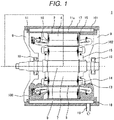
- Fig. 1 is a sectional view in an axial direction of a rotating electrical machine as Example 1 of the invention.
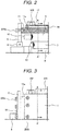
- Fig. 2 is a partial sectional view illustrating the vicinity of an end portion in the axial direction of the rotating electrical machine of Example 1.
- Fig. 3 is a partial side view illustrating the external appearance of the vicinity of the end portion in the axial direction of the rotating electrical machine of Example 1.
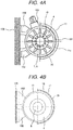
- Figs. 4A to 4C are sectional views in a direction orthogonal to a rotary shaft of the rotating electrical machine of Example 1. Further, Figs. 4A to 4C illustrate cross sections respectively taken along line A-A' in Fig. 2 .
- Fig. 1 is a sectional view in an axial direction of a rotating electrical machine as Example 1 of the invention.
- Fig. 2 is a partial sectional view illustrating the vicinity of an end portion in the axial direction of the rotating electrical machine of Example 1.
- Fig. 3 is a partial side view illustrating the external appearance of the vicinity of the end portion in the
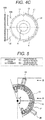
- FIG. 5 is a sectional view in the direction orthogonal to the rotary shaft of a cooling frame 17 of the rotating electrical machine of Example 1. Further, Fig. 5 illustrates a cross section taken along line A-A' in Fig. 3 .
- Fig. 6 is a partial external view of the cooling frame 17 of the rotating electrical machine of Example 1. Further, Fig. 6 is a view which is seen from a direction of B-B' indicated by arrows in Fig. 5 .
- a rotating electrical machine 1 illustrated in Fig. 1 includes a stator 2; a rotor 3 that is rotatably held in an inner circumference of the stator 2 and is disposed to face the stator 2 with a gap therebetween; and the cooling frame 17 that cools the rotating electrical machine 1 from the outer side of a housing 11 by circulating a liquid refrigerant 101.
- the stator 2 includes a stator core 4, and a stator winding that is wound around the stator core 4, and the stator core 4 includes a plurality of teeth cores protruding in a radial direction from an annular yoke core, and slots that are present between the teeth cores and accommodate the stator winding.
- the rotor 3 includes a shaft 8 that is rotatably held by a bearing 10, and a rotor core 7 fixed to the shaft 8.
- the rotor core 7 includes a plurality of teeth cores protruding in a radial direction from an annular yoke core, and a plurality of slots that are present between the teeth cores and accommodate a plurality of conductor bars 13.
- the plurality of conductor bars 13 are electrically connected by an annular end ring 14.
- the stator core 4 and the rotor core 7 are configured of a plurality of magnetic steel plates (for example, silicon sheets) stacked in a rotary shaft direction, and are supported by a pressing plate 15 at an end portion in the rotary shaft direction.
- magnetic steel plates for example, silicon sheets
- the stator 2 having an approximately cylindrical shape is accommodated in an inner circumferential surface of the housing 11 having an approximately cylindrical shape (refer to Figs. 4A and 4B ).
- An end bracket 9 to which the bearing 10 is attached is fixed to each of openings at opposite ends of the housing 11.
- the end bracket 9 is fixed to the housing 11 by using a bolt 200a to be inserted into the end bracket 9 and a screw hole provided on an end surface of the housing 11.
- the rotor 3 is rotatably shaft-supported by the bearing 10 and the end bracket 9 by using the bearing 10 as a bearing of the shaft 8.
- the cooling frame 17 having an approximate semi-circular shape or an approximate semi-cylindrical shape as described below is fixed to the housing 11 so as to partially (in this example, half-circumference) cover an outer circumferential surface of a main body portion 11a of the housing 11 having an approximately cylindrical shape.
- the cooling frame 17 is fixed to the housing 11 by using a bolt 200b inserted from the outer circumferential side surface of the cooling frame 17 and a screw hole provided on the outer circumferential side surface of the housing 11.
- the cooling frame 17 is detachably fixed to the housing 11. As illustrated in Figs.
- the cooling frame 17 in a state where the cooling frame 17 is attached to the housing 11, the end portion of the cooling frame 17 is separated from the end bracket 9. Accordingly, in a state where the cooling frame 17 is attached to the housing 11, the main body portion 11a of the housing 11 is present between the end portion of the cooling frame 17 and the end bracket 9, and thus the cooling frame 17 is not in contact with the end bracket 9. Thus, the cooling frame 17 can be easily detached from the housing 11 without interference with the end bracket 9.
- a clearance formed between the outer circumferential surface of the housing 11 and the inner circumferential surface of the cooling frame 17 is filled with the liquid refrigerant 101 for cooling the rotating electrical machine 1.
- the liquid refrigerant 101 is circulated in a flow path 18 formed of the clearance.
- the cooling frame 17 is provided with an inlet 19 ( Figs. 1 , 5 , and 6 ) for allowing the liquid refrigerant 101 to flow into the flow path 18 from the outside, and an outlet 20 ( Fig. 5 ) for allowing the liquid refrigerant 101 flowing in the flow path 18 to flow out to the outside.
- the rotating electrical machine 1 of Example 1 is installed to a pedestal 105 that is separately provided from the rotating electrical machine 1, and rotates a load.
- a plurality of attachment legs 102 for fixing the rotating electrical machine 1 to the pedestal 105 are provided on the outer circumferential surface of the main body portion 11a of the housing 11.
- the rotating electrical machine 1 is installed to a vertical plane of the pedestal 105.
- Such an installation method is used in, for example, electric railway vehicles.
- the cooling frame 17 having an approximate semi-circular shape or an approximate semi-cylindrical shape is attached to the outer circumferential surface of the housing 11 at a location where the cooling frame 17 does not interfere with a connection portion between the attachment legs 102 and the housing 11, and a power supply cable terminal block 103 by avoiding the connection portion and the power supply cable terminal block 103.
- the attachment legs 102 and the power supply cable terminal block 103 are provided on a half-circumference of the outer circumferential surface of the housing 11, and the cooling frame 17 is provided on the other half-circumference of the outer circumferential surface of the housing 11.
- the cross section of the cooling frame 17 is an arc shape having a central angle, which has a rotational center of the rotating electrical machine 1 as a center, of 180 degrees or less, and in this example, is a semi-arc shape having a central angle of approximately 180 degrees .
- the cooling frame 17 is detachably fixed to the housing 11. Further, the cooling frame 17 can be easily detached from the housing 11 without interference with the attachment legs 102 or the power supply cable terminal block 103.
- the power supply cable terminal block 103 is fixed to the outer circumferential surface of the housing 11 and is electrically connected to the stator winding in the housing 11. Further, the power supply cable terminal block 103 is used for connecting the rotating electrical machine 1 to an external power supply.
- the cooling frame 17 by setting the cooling frame 17 to have an approximate semi-circular shape or an approximate semi-cylindrical shape, it is possible to significantly reduce the weight of the cooling frame 17. That is, it is possible to reduce the size and weight of the cooling frame 17 without using general methods such as using a light-weight material for the constituent material of the cooling frame or the housing, or thinning the thickness of the cooling frame or the housing. Accordingly, it is possible to obtain a cooling structure capable of obtaining a reduction in size and weight while securing the strength.
- Example 1 since the size of the cooling frame 17 can be reduced, the length of the flow path 18 of the liquid refrigerant 101, or the pressure loss in the flow path 18 during the circulation of the liquid refrigerant can be reduced. Therefore, it is possible to reduce the pump capacity for circulating the liquid refrigerant 101. Thus, it is possible to reduce an installation space and costs of a rotating electrical machine system that is provided with the rotating electrical machine and a cooling device.
- the clearance between the cooling frame 17 and the housing 11 becomes the flow path 18 of the liquid refrigerant 101, and such a clearance is formed by forming a groove on the inner circumferential surface of the cooling frame 17 or the outer circumferential surface of the housing 11.
- the cooling frame 17 since the cooling frame 17 has a semi-circular shape or a semi-cylindrical shape, it is easy to perform grooving on the inner circumferential surface of the cooling frame 17.
- Fig. 4B illustrates an example of a cooling structure in which grooves are formed on the inner circumferential surface of the cooling frame 17
- Fig. 4C illustrates an example of a cooling structure in which grooves are formed on the outer circumferential surface of the housing.
- grooves may be formed on both of the cooling frame 17 and the housing 11.
- the cross section of the cooling frame 17 is an arc shape having a central angle, which has the rotational center of the rotating electrical machine 1 as a center, of 180 degrees or less as illustrated in Fig. 5 . That is, the cooling frame 17 is preferable as long as the shape thereof is a semi-cylindrical shape having a central angle of 180 degrees, or a partially cylindrical shape having a central angle smaller than that of the semi-cylindrical shape. As illustrated in Fig. 5 , the cooling frame 17 of Example 1 has a semi-cylindrical shape in which the cross section including a bolt fastening portion is an arc shape having a central angle ⁇ of approximately 180 degrees .
- the cooling frame 17 can be detachably fixed to the housing 11, and can be easily detached from the housing 11 without interference with the attachment legs 102 or the power supply cable terminal block 103. Further, in a state where bolt fastening is released, the cooling frame 17 can be attached or detached while being moved in an axial direction, a radial direction, and a circumferential direction of the rotating electrical machine 1. Therefore, assembly work or maintenance work of the cooling frame 17 becomes easy, and thus workability is improved. In addition, since the cooling frame 17 does not interfere with the end bracket 9, the degree of freedom of an assembly method for the cooling frame 17, the housing 11, and the end bracket 9 is increased. Further, it is possible to attach the cooling frame 17 to an arbitrary position by appropriately providing a screw hole.
- the flow path 18 is formed on the inner circumferential surface of the cooling frame 17 so that the liquid refrigerant is circulated in a direction parallel to an axial line of the rotary shaft (in Fig. 6 , direction of rightward and leftward arrows) .
- the length in the axial direction of the flow path 18 is formed to be longer than the length in the axial direction of the stator 2. In doing so, heat from the stator 2 of which the temperature is increased is sufficiently transferred to the liquid refrigerant 101.
- the direction of the flow path 18 is not limited to the above-described direction, and the flow path 18 may be formed so that the liquid refrigerant 101 is circulated in the circumferential direction of the rotation seen from the rotary shaft direction (in Fig. 6 , direction of upward and downward arrows) .
- the flow path 18 is formed such that the liquid refrigerant 101 is circulated over the approximately entire region of the inner circumferential surface of the cooling frame 17 except edge portions thereof that include the bolt fastening portion and a portion where an O-ring is mounted (O-ring groove 104) by using both the flow path in a direction parallel to the axial line of the rotary shaft and the flow path in the circumferential direction of the rotation. In doing so, since the region through which the liquid refrigerant 101 is circulated covers the region of the stator 2 over the length thereof in the axial direction, cooling efficiency is improved.
- Example 1 if the stator 2 for the region which is covered by the cooling frame 17 is cooled, a thermal gradient is formed within the stator 2 in the radial direction, the circumferential direction, and the axial direction inside. If the thermal gradient is formed, heat conduction is promoted. Therefore, even if the stator 2 can be partially cooled, cooling efficiency for causing the high power output of the rotating electrical machine 1 can be obtained. Specifically, as in Example 1, if a cooling frame having a semi-circular shape or a semi-cylindrical shape is used, cooling efficiency is more reliably obtained.
- the O-ring groove 104 on which an O-ring for sealing the liquid refrigerant 101 is mounted is provided along the outer circumferential edge portion of the inner circumferential surface of the cooling frame 17. That is, the O-ring groove 104 is formed to be a cylindrical seat along the circumferential direction of the housing 11 and to be a raised face along a direction parallel to the rotary shaft in the cooling frame 17.
- the cooling frame 17 is fixed to the housing 11 by bolt fastening at a plurality of locations.
- a plurality of screw holes are provided on the housing 11 at positions facing the outer circumference of the O-ring groove 104.
- the screw hole is formed to have a depth for not penetrating the main body portion 11a of the housing 11. In this manner, the liquid refrigerant 101 inside the cooling frame 17 is prevented from leaking to the inside of the housing 11 through the screw hole.
- the bolts are disposed such that the axial direction of each bolt coincides with the radial direction of the rotating electrical machine 1. In doing so, inertial force or a heat load is almost uniformly divided into each bolt. Further, a shearing load or bending moment acting in a direction other than the axial direction of the bolt is suppressed, and sealing properties of the liquid refrigerant 101 are improved.
- the cooling frame 17 By allowing the power supply cable terminal block to protrude through a notch portion or an opening provided to a part of the cooling frame 17, it is possible to provide a power supply cable within a region where the cooling frame 17 is attached.
- the region where the cooling frame 17 is attached, and the region where the power supply cable is provided are independent from each other, and the cooling frame 17 has a general semi-circular shape or a general semi-cylindrical shape with no notch portion or opening. Therefore, the reliability of sealing for the liquid refrigerant 101 is improved.
- Example 2 a rotating electrical machine as Example 2 of the invention will be described.
- the configuration itself of Example 2 is the same as that of Example 1.
- Example 2 the cooling frame 17 having a semi-circular shape or a semi-cylindrical shape in Example 1 is attached to the housing 11 at a location where the temperature in a non-cooling state is highest in the circumferential direction of the stator 2 and the rotor 3. Accordingly, the attaching position of the cooling frame 17 in Example 2 can be obtained by shifting the cooling frame 17 from the position in Example 1 in the circumferential direction. In this manner, in the circumferential direction of the rotating electrical machine 1, the peak temperature is decreased and the temperature distribution becomes uniform. Accordingly, unevenness of the temperature may not be considered for the setting of the size or the strength of the cooling frame 17, and thus the size and the weight of the cooling frame 17 can be reduced.
- Example 2 can be applied to a case where unevenness of the temperature is caused due to the operating form or the operating environment of the rotating electrical machine 1 as well as a case where unevenness of the temperature is caused due to the structure of the rotating electrical machine.
- the rotating electrical machine is used as a driving source of a moving object such as motor vehicles or railway vehicles.
- the cooling effect due to counter-wind becomes uneven by the way that counter-wind bumps against the rotating electrical machine during the traveling, and thus unevenness of the temperature is caused.
- the portion is cooled due to convective heat transfer.
- the temperature of a location where counter-wind does not bump becomes higher than that of the location where counter-wind bumps.
- the temperature distribution of the rotating electrical machine 1 can become uniform by attaching the cooling frame 17 having a semi-circular shape or a semi-cylindrical shape to a location where counter-wind does not bump.
- the flow path 18 and a flow path wall 21 for circulating the liquid refrigerant 101 are formed on the approximately entire surface of the outer circumferential surface of the housing 11, and thus the rotating electrical machine 1 illustrated in Fig. 4C can substantially function as Example 2.
- Example 3 a rotating electrical machine as Example 3 of the invention will be described.
- the configuration itself of Example 3 is the same as that of Example 1.
- the rotating electrical machine 1 according to Example 3 is used as an air cooling type rotating electrical machine without the cooling frame 17, by using the fact that the cooling frame 17 can be attached or detached without interference with other portions of the rotating electrical machine.
- the attachment legs 102 are provided to the housing 11, the rotating electrical machine according to Example 3 can be installed in the same manner as a case in which cooling is performed by a liquid cooling type rotating electrical machine, by attaching the cooling frame 17 thereto without using other members.
- Example 3 a rotating electrical machine capable of being easily applied to both of a liquid cooling type and an air cooling type can be implemented.
- the specifications except the cooling type are the same as each other, regarding the liquid cooling type rotating electrical machine and the air cooling type rotating electrical machine, communization for components such as the housing 11, the cooling frame 17, and the attachment legs 102 can be obtained. Therefore, productivity is improved and costs are reduced.
- the rotating electrical machine 1 illustrated in Fig. 4C functions as Example 3
- the flow path 18 and the flow path wall 21 for the liquid refrigerant 101 which are provided on the approximately entire surface of the outer circumferential surface of the housing 11, act as radiation fins. Therefore, cooling efficiency is improved. Specifically, in a case where air cooling is performed by counter-wind as in motor vehicles or railway vehicles, the cooling effect becomes great.
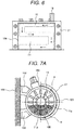
- Example 4 of the invention will be described with reference to Figs. 7A and 7B .
- Figs. 7A and 7B are sectional views in a direction orthogonal to a rotary shaft of a rotating electrical machine as Example 4 of the invention.
- the configuration itself of Example 4 is the same as that of Example 1.
- the difference from Example 1 is mainly described.
- Example 4 the housing 11, that is, the rotating electrical machine 1 is filled with, and stores a liquid refrigerant 100 which is different from the liquid refrigerant 101 circulating in the cooling frame 17.
- the housing is filled with the liquid refrigerant 100 with an amount of the liquid level of the liquid refrigerant 100 to be positioned below the rotation center in a state where the rotor is stopped.
- the amount of the liquid refrigerant 100 is not limited thereto and can be appropriately set.
- the liquid refrigerant 100 and the liquid refrigerant 101 may be the same kind or the different kind.
- the liquid refrigerant 100 may be oil and the liquid refrigerant 101 may be water, or both the liquid refrigerant 100 and the liquid refrigerant 101 may be oil.
- the liquid refrigerant 100 in the rotating electrical machine 1 cools the stator 2 and the rotor 3 immersed in the liquid refrigerant 100.
- the liquid refrigerant 100 is scooped up by the conductor bar 13 and the end ring 14 of the rotor 3, in the rotating electrical machine 1.
- a coil end 16 and the stator core 4 which are not immersed in the liquid refrigerant 100 are cooled by being showered with the liquid refrigerant which is scooped up.
- the liquid refrigerant 100 stored in the rotating electrical machine 1 is cooled by the heat absorption of the liquid refrigerant 101 flowing in the cooling frame 17.
- radiation fins may be formed on the surface on the half-circumference, which is exposed without being covered by the cooling frame 17, of the outer circumferential surface of the housing 11.
- the flow path 18 and the flow path wall 21 provided on the surface of the housing 11 may be used as radiation fins.
- the liquid refrigerant 100 is also cooled by the heat exchange between the air coming into contact with the radiation fins and the liquid refrigerant 100 in the rotating electrical machine 1. Therefore, the cooling performance in the entirety of the rotating electrical machine 1 is improved.
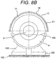
- Example 5 will be described with reference to Figs. 8A and 8B .
- Figs. 8A and 8B are sectional views in a direction orthogonal to a rotary shaft of a rotating electrical machine as Example 5 of the invention.
- the configuration itself of Example 5 is the same as that of Example 1.
- the housing 11, that is, the rotating electrical machine 1 is filled with the liquid refrigerant 100 similar to Example 4.
- Example 1 and Example 4 the difference from Example 1 and Example 4 is mainly described.
- the rotating electrical machine 1 of Example 5 is installed on a horizontal plane of the pedestal 105.
- the cooling frame 17 having a semi-circular shape or a semi-cylindrical shape is disposed on the outer circumferential surface of the main body portion 11a of the housing 11 at a position adjacent to a portion which is not immersed in the liquid refrigerant 100 in the housing 11.
- the portion immersed in the liquid refrigerant 100 is cooled by the liquid refrigerant 100, and the portion which is not immersed in the liquid refrigerant 100 is cooled by the liquid refrigerant 101.
- the liquid refrigerant 100 is cooled by the heat exchange between the air coming into contact with the outer surface of the housing 11, which is exposed to the outside, and the liquid refrigerant 100.
- Example 5 the temperature in the circumferential direction in the rotating electrical machine 1 becomes uniform and the cooling performance in the entirety of the rotating electrical machine 1 is improved.
- radiation fins may be formed on the surface on the half-circumference, which is exposed without being covered by the cooling frame 17, of the outer circumferential surface of the housing 11. That is, the radiation fins may be provided on the outer circumferential surface of the main body portion 11a of the housing 11 at a position adjacent to a portion which is immersed in the liquid refrigerant 100 in the housing 11.
- the flow path 18 and the flow path wall 21 provided on the surface of the housing 11 may be used as radiation fins. According to this configuration, since the liquid refrigerant 100 can be efficiently cooled by the radiation fins, the cooling performance in the entirety of the rotating electrical machine 1 is improved.
- Example 6 of the invention and a modification example thereof will be described with reference to Figs. 9 to 11 .
- the arrows with no reference numerals indicate the direction of the flow of the liquid refrigerant 100 or the liquid refrigerant 101.
- Fig. 9 illustrates a configuration of a cooling system of a rotating electrical machine as Example 6 of the invention.
- the cooling system includes the rotating electrical machine 1 and the cooling device thereof; however, the rotating electrical machine 1 of Example 5 is applied to Example 6.
- the rotating electrical machine according to other examples may be applied thereto (the same is applied to the modification example described below).
- the liquid refrigerant 101 flowing in the cooling frame 17 flows out through the outlet 20 of the cooling frame 17 and flows in a pipe 150 to reach a pump 107.
- the liquid refrigerant 101 that has reached the pump 107 flows in the pipe 150 to reach a heat exchanger 112.
- the liquid refrigerant 101 that has reached the heat exchanger 112 is cooled by the heat exchanger 112 and then flows in the pipe 150 to reach the inlet 19 of the cooling frame 17.
- the liquid refrigerant 101 that has reached the inlet 19 flows into the cooling frame 17 through the inlet 19, and then flows in the cooling frame 17 to flow out through the outlet 20.
- the liquid refrigerant 101 is driven to be circulated between the cooling frame 17 and the heat exchanger 112 by the pump. In this manner, by circulating the liquid refrigerant 101 in a heat exchange cycle in the cooling device of Example 6, the rotating electrical machine 1 is cooled with high efficiency.
- Example 6 by connecting the power supply cable terminal block 103 to a power supply 106 by using a power cable 160, three-phase alternating-current power 108 is supplied from a main circuit of the power supply 106 to the rotating electrical machine 1.
- the power supply 106 is a part of passage through which the liquid refrigerant 101 passes.
- the liquid refrigerant 101 passes through a cooling fin of the main circuit. Accordingly, the power supply 106 is also cooled by the liquid refrigerant 101 with high efficiency.
- Fig. 10 illustrates a configuration of a cooling system of a rotating electrical machine as a modification example of Example 6. Hereinafter, the difference from Example 6 is described.
- the liquid refrigerant 100 stored in the housing of the rotating electrical machine 1 is pumped out to the outside of the rotating electrical machine 1 by a pump 109.
- the liquid refrigerant 100 that is pumped out is driven to be fed to the rotating electrical machine 1 by the pump 109 and is discharged into the housing through a discharging port provided to the housing.
- the discharging port is provided on a side where the stator 2 and the rotor 3 are not immersed in the liquid refrigerant 100. In doing so, the portion where the stator 2 and the rotor 3 are not immersed in the liquid refrigerant 100 is showered with the discharged liquid refrigerant 100 to be cooled. Accordingly, similar to Example 5, temperature in the circumferential direction in the rotating electrical machine 1 becomes uniform and the cooling performance in the entirety of the rotating electrical machine 1 is improved.
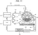
- Fig. 11 illustrates a configuration of a cooling system of a rotating electrical machine as another modification example of Example 6. Hereinafter, the difference from Example 6 is described.
- the liquid refrigerant 100 which is pumped out to the outside of the rotating electrical machine 1 by the pump 109, passes through a heat exchanger 111 and then is discharged into the rotating electrical machine 1. In doing so, the liquid refrigerant 100 is discharged into the rotating electrical machine 1 after being cooled by the heat exchanger 111. Accordingly, the temperature in the circumferential direction in the rotating electrical machine 1 becomes uniform and the effect of reducing the temperature in the rotating electrical machine 1 is improved.
- the invention is not limited to the examples described above, and includes various modification examples.
- the examples described above are described in detail in order to easily understand the invention, and the invention is not limited to an example essentially including all the configurations described above.
- addition, deletion, and replacement of other configurations can be made to a part of the configuration of each example.
- a plurality of cooling frames 17 may be provided.
- the cooling structure of the rotating electrical machine 1 in each example is not limited to a motor, and may be applied to a generator.
Landscapes
- Engineering & Computer Science (AREA)
- Power Engineering (AREA)
- Physics & Mathematics (AREA)
- Thermal Sciences (AREA)
- Motor Or Generator Cooling System (AREA)
- Motor Or Generator Frames (AREA)
Applications Claiming Priority (1)
| Application Number | Priority Date | Filing Date | Title |
|---|---|---|---|
| JP2015127263A JP6560033B2 (ja) | 2015-06-25 | 2015-06-25 | 回転電機、並びに回転電機の冷却システム |
Publications (2)
| Publication Number | Publication Date |
|---|---|
| EP3109977A1 EP3109977A1 (en) | 2016-12-28 |
| EP3109977B1 true EP3109977B1 (en) | 2019-05-01 |
Family
ID=56096526
Family Applications (1)
| Application Number | Title | Priority Date | Filing Date |
|---|---|---|---|
| EP16172145.1A Not-in-force EP3109977B1 (en) | 2015-06-25 | 2016-05-31 | Rotating electrical machine and cooling system of rotating electrical machine |
Country Status (3)
| Country | Link |
|---|---|
| US (1) | US20160380504A1 (enExample) |
| EP (1) | EP3109977B1 (enExample) |
| JP (1) | JP6560033B2 (enExample) |
Families Citing this family (8)
| Publication number | Priority date | Publication date | Assignee | Title |
|---|---|---|---|---|
| JP6302736B2 (ja) * | 2014-04-28 | 2018-03-28 | 日立オートモティブシステムズ株式会社 | 回転電機 |
| JP6526647B2 (ja) * | 2014-05-27 | 2019-06-05 | 三菱電機株式会社 | 回転電機 |
| CN106936270B (zh) * | 2017-04-22 | 2019-12-24 | 宣城立创自动化科技有限公司 | 发电装置装配方法 |
| DE112018003847T5 (de) * | 2017-07-28 | 2020-04-09 | Nidec Corporation | Motor |
| SE544011C2 (en) * | 2019-11-05 | 2021-11-02 | Scania Cv Ab | An electric machine with an integrated heat exchanger |
| CN112366882B (zh) * | 2021-01-11 | 2021-05-07 | 宁波东腾机械制造有限公司 | 一种便于散热的汽车马达机壳及其安装制造工艺和应用 |
| CN117751511B (zh) * | 2022-03-25 | 2025-03-11 | 广东逸动科技有限公司 | 电机、船用推进器及船舶 |
| CN117375298B (zh) * | 2023-10-19 | 2024-05-07 | 江苏中车电机有限公司 | 一种用于发电机的冷却装置 |
Family Cites Families (27)
| Publication number | Priority date | Publication date | Assignee | Title |
|---|---|---|---|---|
| GB874748A (en) * | 1958-04-11 | 1961-08-10 | Scott L & Electromotors Ltd | Improvements relating to the cooling of electric motors |
| US4516044A (en) * | 1984-05-31 | 1985-05-07 | Cincinnati Milacron Inc. | Heat exchange apparatus for electric motor and electric motor equipped therewith |
| US4854373A (en) * | 1988-03-30 | 1989-08-08 | Williams Gordon G | Heat exchanger for a pump motor |
| US5519269A (en) * | 1994-06-10 | 1996-05-21 | Westinghouse Electric Corp. | Electric induction motor and related method of cooling |
| US5906236A (en) * | 1997-07-28 | 1999-05-25 | Heatflo Systems, Inc. | Heat exchange jacket for attachment to an external surface of a pump motor |
| DE19817333C5 (de) * | 1998-04-18 | 2007-04-26 | Conti Temic Microelectronic Gmbh | Elektrische Antriebseinheit aus Elektromotor und Elektronikmodul |
| JP3040748B2 (ja) * | 1998-06-15 | 2000-05-15 | ジーイー横河メディカルシステム株式会社 | Mri用垂直マグネット装置およびmri装置 |
| JP3748249B2 (ja) | 2001-10-15 | 2006-02-22 | 株式会社安川電機 | 電動機の冷却装置 |
| JP4267373B2 (ja) * | 2003-05-30 | 2009-05-27 | 株式会社日本自動車部品総合研究所 | 車両用電動機冷却システム |
| US6909210B1 (en) * | 2004-02-06 | 2005-06-21 | Emerson Electric Co. | Cooling system for dynamoelectric machine |
| JP4501667B2 (ja) * | 2004-12-14 | 2010-07-14 | 三菱電機株式会社 | 車両駆動装置 |
| US20110036617A1 (en) * | 2007-08-03 | 2011-02-17 | Leonid Kokurin | Compensating Conductive Circuit |
| FI120782B (fi) * | 2008-04-18 | 2010-02-26 | Abb Oy | Jäähdytyselementti sähkökoneeseen |
| DE102008001622A1 (de) * | 2008-05-07 | 2009-11-12 | Robert Bosch Gmbh | Elektrische Maschine mit Sprüh- und Sumpfkühlung |
| JP5146363B2 (ja) | 2009-03-04 | 2013-02-20 | ダイキン工業株式会社 | 電動機 |
| JP4648470B2 (ja) * | 2009-07-03 | 2011-03-09 | ファナック株式会社 | 電動機冷却装置 |
| JP2011109766A (ja) * | 2009-11-16 | 2011-06-02 | Canon Anelva Corp | モータ冷却ユニット及びモータ |
| US8346776B2 (en) * | 2010-05-17 | 2013-01-01 | International Business Machines Corporation | Generating a taxonomy for documents from tag data |
| CA2801084A1 (en) * | 2010-06-04 | 2011-12-08 | Remy Technologies, Llc | Electric machine cooling system and method |
| WO2012114420A1 (ja) * | 2011-02-21 | 2012-08-30 | 株式会社日立製作所 | 冷却装置、及び、該冷却装置を備えたモータとインバータ |
| JP2012191718A (ja) * | 2011-03-09 | 2012-10-04 | Hitachi Constr Mach Co Ltd | 永久磁石式発電電動機および油圧ショベル用永久磁石式発電電動機 |
| US9735654B2 (en) * | 2011-03-09 | 2017-08-15 | Stridsberg Innovation Ab | Cooled magnet motor |
| JP5652359B2 (ja) * | 2011-09-12 | 2015-01-14 | 株式会社豊田自動織機 | 電動圧縮機 |
| JP5706793B2 (ja) * | 2011-09-20 | 2015-04-22 | 日立建機株式会社 | 発電電動機とこれを用いた電動車両 |
| TWI477039B (zh) * | 2011-11-23 | 2015-03-11 | Delta Electronics Inc | 冷卻套 |
| CN104885339B (zh) * | 2012-12-21 | 2018-05-04 | 万高电机设备公司 | 旋转电机壳体的热交换系统 |
| WO2015008390A1 (ja) * | 2013-07-19 | 2015-01-22 | 株式会社 東芝 | 液冷式電動機 |
-
2015
- 2015-06-25 JP JP2015127263A patent/JP6560033B2/ja not_active Expired - Fee Related
-
2016
- 2016-04-25 US US15/137,177 patent/US20160380504A1/en not_active Abandoned
- 2016-05-31 EP EP16172145.1A patent/EP3109977B1/en not_active Not-in-force
Non-Patent Citations (1)
| Title |
|---|
| None * |
Also Published As
| Publication number | Publication date |
|---|---|
| JP2017011946A (ja) | 2017-01-12 |
| EP3109977A1 (en) | 2016-12-28 |
| US20160380504A1 (en) | 2016-12-29 |
| JP6560033B2 (ja) | 2019-08-14 |
Similar Documents
| Publication | Publication Date | Title |
|---|---|---|
| EP3109977B1 (en) | Rotating electrical machine and cooling system of rotating electrical machine | |
| US7443062B2 (en) | Motor rotor cooling with rotation heat pipes | |
| US11309756B2 (en) | Motor | |
| JP5441607B2 (ja) | 電気機械を冷却するための装置 | |
| US7675209B2 (en) | Electric motor cooling jacket | |
| US8803380B2 (en) | Electric machine module cooling system and method | |
| US9755482B2 (en) | Electric machine with liquid cooling and method of assembling | |
| KR20130141502A (ko) | 전기 기계 고정자를 위한 냉각제 채널 | |
| US20140246933A1 (en) | Liquid-cooled rotary electric machine having heat source-surrounding fluid passage | |
| US20120286595A1 (en) | Enhanced dual liquid cooling system for electric motor | |
| RU169220U1 (ru) | Электрическая машина с теплопроводным устройством | |
| US10038353B2 (en) | Dual-rotor electric rotating machine | |
| JP6628779B2 (ja) | 機電一体型回転電機装置 | |
| US20140246177A1 (en) | Liquid-cooled rotary electric machine having cooling jacket with bi-directional flow | |
| EP3955434B1 (en) | Cooling device, motor and wind turbine generator set | |
| CN105048662A (zh) | 电机的散热 | |
| JP2014135817A (ja) | 回転電機 | |
| JP2019161752A (ja) | 回転電機のステータ | |
| US20140246931A1 (en) | Liquid-cooled rotary electric machine having fluid channel with auxiliary coolant groove | |
| US11018548B2 (en) | Electrical machine having a frame and sleeve | |
| CN110224552A (zh) | 一种双重冷却的电机结构 | |
| US9356490B2 (en) | Electric machine and method to retrofit an electric machine | |
| JP2014087248A (ja) | 液冷式の回転電機および回転電機システム | |
| JP2011250601A (ja) | 電動機 | |
| JP2017085830A (ja) | 回転電機 |
Legal Events
| Date | Code | Title | Description |
|---|---|---|---|
| PUAI | Public reference made under article 153(3) epc to a published international application that has entered the european phase |
Free format text: ORIGINAL CODE: 0009012 |
|
| STAA | Information on the status of an ep patent application or granted ep patent |
Free format text: STATUS: REQUEST FOR EXAMINATION WAS MADE |
|
| 17P | Request for examination filed |
Effective date: 20160617 |
|
| AK | Designated contracting states |
Kind code of ref document: A1 Designated state(s): AL AT BE BG CH CY CZ DE DK EE ES FI FR GB GR HR HU IE IS IT LI LT LU LV MC MK MT NL NO PL PT RO RS SE SI SK SM TR |
|
| AX | Request for extension of the european patent |
Extension state: BA ME |
|
| STAA | Information on the status of an ep patent application or granted ep patent |
Free format text: STATUS: EXAMINATION IS IN PROGRESS |
|
| 17Q | First examination report despatched |
Effective date: 20180220 |
|
| GRAP | Despatch of communication of intention to grant a patent |
Free format text: ORIGINAL CODE: EPIDOSNIGR1 |
|
| STAA | Information on the status of an ep patent application or granted ep patent |
Free format text: STATUS: GRANT OF PATENT IS INTENDED |
|
| INTG | Intention to grant announced |
Effective date: 20181219 |
|
| GRAS | Grant fee paid |
Free format text: ORIGINAL CODE: EPIDOSNIGR3 |
|
| GRAA | (expected) grant |
Free format text: ORIGINAL CODE: 0009210 |
|
| STAA | Information on the status of an ep patent application or granted ep patent |
Free format text: STATUS: THE PATENT HAS BEEN GRANTED |
|
| AK | Designated contracting states |
Kind code of ref document: B1 Designated state(s): AL AT BE BG CH CY CZ DE DK EE ES FI FR GB GR HR HU IE IS IT LI LT LU LV MC MK MT NL NO PL PT RO RS SE SI SK SM TR |
|
| REG | Reference to a national code |
Ref country code: GB Ref legal event code: FG4D |
|
| REG | Reference to a national code |
Ref country code: CH Ref legal event code: EP Ref country code: AT Ref legal event code: REF Ref document number: 1128234 Country of ref document: AT Kind code of ref document: T Effective date: 20190515 |
|
| REG | Reference to a national code |
Ref country code: DE Ref legal event code: R096 Ref document number: 602016013052 Country of ref document: DE |
|
| REG | Reference to a national code |
Ref country code: IE Ref legal event code: FG4D |
|
| REG | Reference to a national code |
Ref country code: NL Ref legal event code: MP Effective date: 20190501 |
|
| REG | Reference to a national code |
Ref country code: LT Ref legal event code: MG4D |
|
| PG25 | Lapsed in a contracting state [announced via postgrant information from national office to epo] |
Ref country code: AL Free format text: LAPSE BECAUSE OF FAILURE TO SUBMIT A TRANSLATION OF THE DESCRIPTION OR TO PAY THE FEE WITHIN THE PRESCRIBED TIME-LIMIT Effective date: 20190501 Ref country code: PT Free format text: LAPSE BECAUSE OF FAILURE TO SUBMIT A TRANSLATION OF THE DESCRIPTION OR TO PAY THE FEE WITHIN THE PRESCRIBED TIME-LIMIT Effective date: 20190901 Ref country code: NL Free format text: LAPSE BECAUSE OF FAILURE TO SUBMIT A TRANSLATION OF THE DESCRIPTION OR TO PAY THE FEE WITHIN THE PRESCRIBED TIME-LIMIT Effective date: 20190501 Ref country code: ES Free format text: LAPSE BECAUSE OF FAILURE TO SUBMIT A TRANSLATION OF THE DESCRIPTION OR TO PAY THE FEE WITHIN THE PRESCRIBED TIME-LIMIT Effective date: 20190501 Ref country code: LT Free format text: LAPSE BECAUSE OF FAILURE TO SUBMIT A TRANSLATION OF THE DESCRIPTION OR TO PAY THE FEE WITHIN THE PRESCRIBED TIME-LIMIT Effective date: 20190501 Ref country code: NO Free format text: LAPSE BECAUSE OF FAILURE TO SUBMIT A TRANSLATION OF THE DESCRIPTION OR TO PAY THE FEE WITHIN THE PRESCRIBED TIME-LIMIT Effective date: 20190801 Ref country code: HR Free format text: LAPSE BECAUSE OF FAILURE TO SUBMIT A TRANSLATION OF THE DESCRIPTION OR TO PAY THE FEE WITHIN THE PRESCRIBED TIME-LIMIT Effective date: 20190501 Ref country code: SE Free format text: LAPSE BECAUSE OF FAILURE TO SUBMIT A TRANSLATION OF THE DESCRIPTION OR TO PAY THE FEE WITHIN THE PRESCRIBED TIME-LIMIT Effective date: 20190501 Ref country code: FI Free format text: LAPSE BECAUSE OF FAILURE TO SUBMIT A TRANSLATION OF THE DESCRIPTION OR TO PAY THE FEE WITHIN THE PRESCRIBED TIME-LIMIT Effective date: 20190501 |
|
| PG25 | Lapsed in a contracting state [announced via postgrant information from national office to epo] |
Ref country code: RS Free format text: LAPSE BECAUSE OF FAILURE TO SUBMIT A TRANSLATION OF THE DESCRIPTION OR TO PAY THE FEE WITHIN THE PRESCRIBED TIME-LIMIT Effective date: 20190501 Ref country code: GR Free format text: LAPSE BECAUSE OF FAILURE TO SUBMIT A TRANSLATION OF THE DESCRIPTION OR TO PAY THE FEE WITHIN THE PRESCRIBED TIME-LIMIT Effective date: 20190802 Ref country code: LV Free format text: LAPSE BECAUSE OF FAILURE TO SUBMIT A TRANSLATION OF THE DESCRIPTION OR TO PAY THE FEE WITHIN THE PRESCRIBED TIME-LIMIT Effective date: 20190501 Ref country code: BG Free format text: LAPSE BECAUSE OF FAILURE TO SUBMIT A TRANSLATION OF THE DESCRIPTION OR TO PAY THE FEE WITHIN THE PRESCRIBED TIME-LIMIT Effective date: 20190801 |
|
| REG | Reference to a national code |
Ref country code: AT Ref legal event code: MK05 Ref document number: 1128234 Country of ref document: AT Kind code of ref document: T Effective date: 20190501 |
|
| REG | Reference to a national code |
Ref country code: CH Ref legal event code: PL |
|
| PG25 | Lapsed in a contracting state [announced via postgrant information from national office to epo] |
Ref country code: IS Free format text: LAPSE BECAUSE OF FAILURE TO SUBMIT A TRANSLATION OF THE DESCRIPTION OR TO PAY THE FEE WITHIN THE PRESCRIBED TIME-LIMIT Effective date: 20190901 |
|
| PG25 | Lapsed in a contracting state [announced via postgrant information from national office to epo] |
Ref country code: MC Free format text: LAPSE BECAUSE OF FAILURE TO SUBMIT A TRANSLATION OF THE DESCRIPTION OR TO PAY THE FEE WITHIN THE PRESCRIBED TIME-LIMIT Effective date: 20190501 Ref country code: SK Free format text: LAPSE BECAUSE OF FAILURE TO SUBMIT A TRANSLATION OF THE DESCRIPTION OR TO PAY THE FEE WITHIN THE PRESCRIBED TIME-LIMIT Effective date: 20190501 Ref country code: CH Free format text: LAPSE BECAUSE OF NON-PAYMENT OF DUE FEES Effective date: 20190531 Ref country code: RO Free format text: LAPSE BECAUSE OF FAILURE TO SUBMIT A TRANSLATION OF THE DESCRIPTION OR TO PAY THE FEE WITHIN THE PRESCRIBED TIME-LIMIT Effective date: 20190501 Ref country code: CZ Free format text: LAPSE BECAUSE OF FAILURE TO SUBMIT A TRANSLATION OF THE DESCRIPTION OR TO PAY THE FEE WITHIN THE PRESCRIBED TIME-LIMIT Effective date: 20190501 Ref country code: DK Free format text: LAPSE BECAUSE OF FAILURE TO SUBMIT A TRANSLATION OF THE DESCRIPTION OR TO PAY THE FEE WITHIN THE PRESCRIBED TIME-LIMIT Effective date: 20190501 Ref country code: EE Free format text: LAPSE BECAUSE OF FAILURE TO SUBMIT A TRANSLATION OF THE DESCRIPTION OR TO PAY THE FEE WITHIN THE PRESCRIBED TIME-LIMIT Effective date: 20190501 Ref country code: AT Free format text: LAPSE BECAUSE OF FAILURE TO SUBMIT A TRANSLATION OF THE DESCRIPTION OR TO PAY THE FEE WITHIN THE PRESCRIBED TIME-LIMIT Effective date: 20190501 Ref country code: LI Free format text: LAPSE BECAUSE OF NON-PAYMENT OF DUE FEES Effective date: 20190531 |
|
| REG | Reference to a national code |
Ref country code: DE Ref legal event code: R097 Ref document number: 602016013052 Country of ref document: DE |
|
| REG | Reference to a national code |
Ref country code: BE Ref legal event code: MM Effective date: 20190531 |
|
| PG25 | Lapsed in a contracting state [announced via postgrant information from national office to epo] |
Ref country code: LU Free format text: LAPSE BECAUSE OF NON-PAYMENT OF DUE FEES Effective date: 20190531 Ref country code: SM Free format text: LAPSE BECAUSE OF FAILURE TO SUBMIT A TRANSLATION OF THE DESCRIPTION OR TO PAY THE FEE WITHIN THE PRESCRIBED TIME-LIMIT Effective date: 20190501 Ref country code: IT Free format text: LAPSE BECAUSE OF FAILURE TO SUBMIT A TRANSLATION OF THE DESCRIPTION OR TO PAY THE FEE WITHIN THE PRESCRIBED TIME-LIMIT Effective date: 20190501 |
|
| PLBE | No opposition filed within time limit |
Free format text: ORIGINAL CODE: 0009261 |
|
| STAA | Information on the status of an ep patent application or granted ep patent |
Free format text: STATUS: NO OPPOSITION FILED WITHIN TIME LIMIT |
|
| PG25 | Lapsed in a contracting state [announced via postgrant information from national office to epo] |
Ref country code: TR Free format text: LAPSE BECAUSE OF FAILURE TO SUBMIT A TRANSLATION OF THE DESCRIPTION OR TO PAY THE FEE WITHIN THE PRESCRIBED TIME-LIMIT Effective date: 20190501 |
|
| 26N | No opposition filed |
Effective date: 20200204 |
|
| PG25 | Lapsed in a contracting state [announced via postgrant information from national office to epo] |
Ref country code: IE Free format text: LAPSE BECAUSE OF NON-PAYMENT OF DUE FEES Effective date: 20190531 Ref country code: PL Free format text: LAPSE BECAUSE OF FAILURE TO SUBMIT A TRANSLATION OF THE DESCRIPTION OR TO PAY THE FEE WITHIN THE PRESCRIBED TIME-LIMIT Effective date: 20190501 |
|
| PG25 | Lapsed in a contracting state [announced via postgrant information from national office to epo] |
Ref country code: BE Free format text: LAPSE BECAUSE OF NON-PAYMENT OF DUE FEES Effective date: 20190531 Ref country code: SI Free format text: LAPSE BECAUSE OF FAILURE TO SUBMIT A TRANSLATION OF THE DESCRIPTION OR TO PAY THE FEE WITHIN THE PRESCRIBED TIME-LIMIT Effective date: 20190501 |
|
| PG25 | Lapsed in a contracting state [announced via postgrant information from national office to epo] |
Ref country code: CY Free format text: LAPSE BECAUSE OF FAILURE TO SUBMIT A TRANSLATION OF THE DESCRIPTION OR TO PAY THE FEE WITHIN THE PRESCRIBED TIME-LIMIT Effective date: 20190501 |
|
| PG25 | Lapsed in a contracting state [announced via postgrant information from national office to epo] |
Ref country code: HU Free format text: LAPSE BECAUSE OF FAILURE TO SUBMIT A TRANSLATION OF THE DESCRIPTION OR TO PAY THE FEE WITHIN THE PRESCRIBED TIME-LIMIT; INVALID AB INITIO Effective date: 20160531 Ref country code: MT Free format text: LAPSE BECAUSE OF FAILURE TO SUBMIT A TRANSLATION OF THE DESCRIPTION OR TO PAY THE FEE WITHIN THE PRESCRIBED TIME-LIMIT Effective date: 20190501 |
|
| PG25 | Lapsed in a contracting state [announced via postgrant information from national office to epo] |
Ref country code: MK Free format text: LAPSE BECAUSE OF FAILURE TO SUBMIT A TRANSLATION OF THE DESCRIPTION OR TO PAY THE FEE WITHIN THE PRESCRIBED TIME-LIMIT Effective date: 20190501 |
|
| PGFP | Annual fee paid to national office [announced via postgrant information from national office to epo] |
Ref country code: GB Payment date: 20220407 Year of fee payment: 7 Ref country code: FR Payment date: 20220408 Year of fee payment: 7 Ref country code: DE Payment date: 20220406 Year of fee payment: 7 |
|
| REG | Reference to a national code |
Ref country code: DE Ref legal event code: R119 Ref document number: 602016013052 Country of ref document: DE |
|
| GBPC | Gb: european patent ceased through non-payment of renewal fee |
Effective date: 20230531 |
|
| PG25 | Lapsed in a contracting state [announced via postgrant information from national office to epo] |
Ref country code: DE Free format text: LAPSE BECAUSE OF NON-PAYMENT OF DUE FEES Effective date: 20231201 Ref country code: GB Free format text: LAPSE BECAUSE OF NON-PAYMENT OF DUE FEES Effective date: 20230531 |
|
| PG25 | Lapsed in a contracting state [announced via postgrant information from national office to epo] |
Ref country code: FR Free format text: LAPSE BECAUSE OF NON-PAYMENT OF DUE FEES Effective date: 20230531 |