EP3109526A1 - Vanne motorisée - Google Patents
Vanne motorisée Download PDFInfo
- Publication number
- EP3109526A1 EP3109526A1 EP16162883.9A EP16162883A EP3109526A1 EP 3109526 A1 EP3109526 A1 EP 3109526A1 EP 16162883 A EP16162883 A EP 16162883A EP 3109526 A1 EP3109526 A1 EP 3109526A1
- Authority
- EP
- European Patent Office
- Prior art keywords
- valve
- shaft
- rotor
- valve body
- motor
- Prior art date
- Legal status (The legal status is an assumption and is not a legal conclusion. Google has not performed a legal analysis and makes no representation as to the accuracy of the status listed.)
- Granted
Links
- 230000001174 ascending effect Effects 0.000 claims description 12
- 230000006835 compression Effects 0.000 abstract description 8
- 238000007906 compression Methods 0.000 abstract description 8
- 239000012530 fluid Substances 0.000 description 4
- 239000003507 refrigerant Substances 0.000 description 2
- 239000011347 resin Substances 0.000 description 2
- 229920005989 resin Polymers 0.000 description 2
- 238000001816 cooling Methods 0.000 description 1
- 238000010438 heat treatment Methods 0.000 description 1
- 238000003780 insertion Methods 0.000 description 1
- 230000037431 insertion Effects 0.000 description 1
- 239000000696 magnetic material Substances 0.000 description 1
- 239000000463 material Substances 0.000 description 1
Images


Classifications
-
- F—MECHANICAL ENGINEERING; LIGHTING; HEATING; WEAPONS; BLASTING
- F16—ENGINEERING ELEMENTS AND UNITS; GENERAL MEASURES FOR PRODUCING AND MAINTAINING EFFECTIVE FUNCTIONING OF MACHINES OR INSTALLATIONS; THERMAL INSULATION IN GENERAL
- F16K—VALVES; TAPS; COCKS; ACTUATING-FLOATS; DEVICES FOR VENTING OR AERATING
- F16K31/00—Actuating devices; Operating means; Releasing devices
- F16K31/02—Actuating devices; Operating means; Releasing devices electric; magnetic
- F16K31/04—Actuating devices; Operating means; Releasing devices electric; magnetic using a motor
- F16K31/047—Actuating devices; Operating means; Releasing devices electric; magnetic using a motor characterised by mechanical means between the motor and the valve, e.g. lost motion means reducing backlash, clutches, brakes or return means
-
- F—MECHANICAL ENGINEERING; LIGHTING; HEATING; WEAPONS; BLASTING
- F16—ENGINEERING ELEMENTS AND UNITS; GENERAL MEASURES FOR PRODUCING AND MAINTAINING EFFECTIVE FUNCTIONING OF MACHINES OR INSTALLATIONS; THERMAL INSULATION IN GENERAL
- F16K—VALVES; TAPS; COCKS; ACTUATING-FLOATS; DEVICES FOR VENTING OR AERATING
- F16K1/00—Lift valves or globe valves, i.e. cut-off apparatus with closure members having at least a component of their opening and closing motion perpendicular to the closing faces
- F16K1/02—Lift valves or globe valves, i.e. cut-off apparatus with closure members having at least a component of their opening and closing motion perpendicular to the closing faces with screw-spindle
-
- F—MECHANICAL ENGINEERING; LIGHTING; HEATING; WEAPONS; BLASTING
- F16—ENGINEERING ELEMENTS AND UNITS; GENERAL MEASURES FOR PRODUCING AND MAINTAINING EFFECTIVE FUNCTIONING OF MACHINES OR INSTALLATIONS; THERMAL INSULATION IN GENERAL
- F16H—GEARING
- F16H25/00—Gearings comprising primarily only cams, cam-followers and screw-and-nut mechanisms
- F16H25/18—Gearings comprising primarily only cams, cam-followers and screw-and-nut mechanisms for conveying or interconverting oscillating or reciprocating motions
- F16H25/20—Screw mechanisms
-
- F—MECHANICAL ENGINEERING; LIGHTING; HEATING; WEAPONS; BLASTING
- F16—ENGINEERING ELEMENTS AND UNITS; GENERAL MEASURES FOR PRODUCING AND MAINTAINING EFFECTIVE FUNCTIONING OF MACHINES OR INSTALLATIONS; THERMAL INSULATION IN GENERAL
- F16K—VALVES; TAPS; COCKS; ACTUATING-FLOATS; DEVICES FOR VENTING OR AERATING
- F16K1/00—Lift valves or globe valves, i.e. cut-off apparatus with closure members having at least a component of their opening and closing motion perpendicular to the closing faces
- F16K1/12—Lift valves or globe valves, i.e. cut-off apparatus with closure members having at least a component of their opening and closing motion perpendicular to the closing faces with streamlined valve member around which the fluid flows when the valve is opened
-
- F—MECHANICAL ENGINEERING; LIGHTING; HEATING; WEAPONS; BLASTING
- F25—REFRIGERATION OR COOLING; COMBINED HEATING AND REFRIGERATION SYSTEMS; HEAT PUMP SYSTEMS; MANUFACTURE OR STORAGE OF ICE; LIQUEFACTION SOLIDIFICATION OF GASES
- F25B—REFRIGERATION MACHINES, PLANTS OR SYSTEMS; COMBINED HEATING AND REFRIGERATION SYSTEMS; HEAT PUMP SYSTEMS
- F25B41/00—Fluid-circulation arrangements
- F25B41/30—Expansion means; Dispositions thereof
- F25B41/31—Expansion valves
- F25B41/34—Expansion valves with the valve member being actuated by electric means, e.g. by piezoelectric actuators
- F25B41/35—Expansion valves with the valve member being actuated by electric means, e.g. by piezoelectric actuators by rotary motors, e.g. by stepping motors
-
- F—MECHANICAL ENGINEERING; LIGHTING; HEATING; WEAPONS; BLASTING
- F16—ENGINEERING ELEMENTS AND UNITS; GENERAL MEASURES FOR PRODUCING AND MAINTAINING EFFECTIVE FUNCTIONING OF MACHINES OR INSTALLATIONS; THERMAL INSULATION IN GENERAL
- F16H—GEARING
- F16H25/00—Gearings comprising primarily only cams, cam-followers and screw-and-nut mechanisms
- F16H25/18—Gearings comprising primarily only cams, cam-followers and screw-and-nut mechanisms for conveying or interconverting oscillating or reciprocating motions
- F16H25/20—Screw mechanisms
- F16H2025/2062—Arrangements for driving the actuator
- F16H2025/2087—Arrangements for driving the actuator using planetary gears
-
- Y—GENERAL TAGGING OF NEW TECHNOLOGICAL DEVELOPMENTS; GENERAL TAGGING OF CROSS-SECTIONAL TECHNOLOGIES SPANNING OVER SEVERAL SECTIONS OF THE IPC; TECHNICAL SUBJECTS COVERED BY FORMER USPC CROSS-REFERENCE ART COLLECTIONS [XRACs] AND DIGESTS
- Y02—TECHNOLOGIES OR APPLICATIONS FOR MITIGATION OR ADAPTATION AGAINST CLIMATE CHANGE
- Y02B—CLIMATE CHANGE MITIGATION TECHNOLOGIES RELATED TO BUILDINGS, e.g. HOUSING, HOUSE APPLIANCES OR RELATED END-USER APPLICATIONS
- Y02B30/00—Energy efficient heating, ventilation or air conditioning [HVAC]
- Y02B30/70—Efficient control or regulation technologies, e.g. for control of refrigerant flow, motor or heating
Definitions
- the present invention relates to motor-driven valves, and relates to a motor-driven valve to control the flow rate of fluid (refrigerant) in a heating and cooling system, for example.
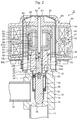
- FIG. 2 shows a conventional example of this type of motor-driven valve.
- a motor-driven valve 1' illustrated as a conventional example basically includes a valve body 10 having a valve chamber 14 and a valve seat 15 formed inside thereof, a circular cylindrical shaped can 30 having a ceiling part that is fixed to the valve body 10 via a base plate 31, a stepping motor 63 including a stator 40 attached outside of the can 30 and a rotor 50 attached inside of the can 30, a planetary gear reduction mechanism 60 to decrease the rotation speed of the rotor 50, a valve element 21 to control the amount of fluid passing while moving close to or away from the valve seat 15, and a screw drive member 22 to convert the rotary motion of an output gear 57 of the planetary gear reduction mechanism 60 into the linear motion via a thread feeding mechanism 27 to drive the valve element 21.
- the valve body 10 includes a valve port 16 defined so as to communicate with the valve chamber 14, and a pipe 11 is connected to a part thereof on the valve port 16 side, and a pipe 12 is connected so as to communicate with an opening formed at the lateral face of the valve chamber 14.
- a threaded bearing member 13 having an internal thread 13a formed at a lower half part thereof on the center is inserted and fitted to the upper part of the valve chamber 14 of the valve body 10, and is fixed to the valve body 10 by caulking (caulking part 17).
- the stator 40 fitted to the outer circumference of the can 30 includes a yoke 41, a bobbin 42, a coil 43, a resin mold 44 and the like, and the rotor 50 rotatably (without moving vertically) supported inside of the can 30 is made up of a circular cylindrical rotor member 51 made of a magnetic material and a sun gear member 52 made of a resin material that are coupled integrally.
- a shaft 62 is inserted at a center part of the sun gear member 52, and an upper part of the shaft 62 is supported by a supporting member 61 disposed inside of the top part of the can 30.
- the sun gear member 52 has a sun gear 53 that meshes with a plurality of planetary gears 55 that is rotatably supported by shafts 56 provided at a carrier 54 placed on the bottom face of the output gear 57.
- the upper half of each planetary gear 55 meshes with an annular ring gear (fixed internal gear) 58 attached by caulking to the upper part of a circular cylindrical member 18 fixed to the upper part of the valve body 10, and the lower half of the planetary gear 55 meshes with an internal gear 57a of the annular output gear 57.
- the ring gear 58 and the internal gear 57a of the output gear 57 have slightly different numbers of teeth, whereby the number of rotations of the sun gear 53 is transmitted to the output gear 57 at a large reduction gear ratio (such a structure of the gears is called a mechanical paradox planetary gear reduction mechanism 60).
- the output gear 57 slidably comes into contact with the upper face of the threaded bearing member 13, and the upper part of a stepped circular cylindrical output shaft 59 is press-fitted to the center of the bottom part of the output gear 57, whereas the lower part of the output shaft 59 is rotatably inserted into an insertion hole 13b formed at the upper half of the center part of the threaded bearing member 13. Then, the lower part of the shaft 62 is fitted to the upper part of the output shaft 59.
- the internal thread 13a of the threaded bearing member 13 threadably engages with an external thread 22a of the screw drive member 22 (this may be called a driver as well) making up a valve shaft 20, and the screw drive member 22 converts the rotary motion of the output gear 57 (i.e., the rotor 50) into the linear motion in the direction of axis line O (vertically ascending/descending direction) through the thread feeding mechanism 27 including the external thread 22a and the internal thread 13a.
- the output gear 57 rotates at a fixed position in the direction of axis line O without moving vertically, and a plate-like portion 22b having a shape like a flat-bladed driver provided at the upper end part of the screw drive member 22 is inserted into a slit-like fitting groove 59b provided at the lower end part of the output shaft 59 coupled with the output gear 57, whereby the rotary motion of the output gear 57 is transmitted to the screw drive member 22.
- the plate-like portion 22b of the screw drive member 22 slides in the direction of axis line O in the fitting groove 59b of the output shaft 59, whereby as the output gear 57 (rotor 50) rotates, the screw drive member 22 linearly moves in the direction of axis line O due to the thread feeding mechanism 27, although the output gear 57 does not move in the direction of rotation axis.
- the linear motion of the screw drive member 22 is transmitted to a shaft-like valve element 21 via a ball-shaped fitting 25 including a ball 23 and a ball receiving seat 24, so that the valve element 21 is guided by a stepped circular cylindrical spring case 19 internally fixed to the valve body 10 to move in the direction of axis line O.
- the space between the spring case 19 and the valve element 21 stores a compression coil spring 26 in a compressed manner so as to always bias the valve element 21 in the valve opening direction.
- valve opening degree the flow passage area between the valve element 21 and the valve seat 15 changes, whereby the flow rate of refrigerant passing through the valve port 16 can be controlled.
- Patent Documents 1 and 2 propose prior art to solve such a problem.
- the overlap width between the lateral face of the fitting groove and the lateral face of the plate-like portion that mutually overlap when viewed from the axis direction (vertically ascending/descending direction) is set larger than the inner diameter of the internal thread of the threaded bearing member.
- the output gear can ascend/descend in a planetary gear reduction mechanism, and the output shaft and the screw drive member are shaped integrally to form the output gear and the screw drive member integrally.
- Patent Document 1 The prior art described in Patent Document 1, however, is configured so that rotary motion of the output gear (rotor) is transmitted to the screw drive member by engagement (mesh) of the fitting groove of the output shaft and the plate-like portion of the screw drive member, and so this cannot solve the problem on hysteresis as stated above sufficiently.
- Patent Document 2 has the possibility of increasing the overall height to keep the strength of the output gear when the gear descends in the planetary gear reduction mechanism, and it has to additionally include a disc spring, for example, to control the position of the rotor in the axis direction, which means a complicated structure.
- the present invention aims to provide a motor-driven valve with a simple configuration that can solve hysteresis generated when the rotary direction changes, without greatly changing a conventional motor-driving valve.
- a motor-driven valve includes: a valve body having a valve chamber and a valve seat; a valve shaft having a valve element that ascends and descends with respect to the valve seat; and a motor including a rotor that rotates without ascending/descending with respect to the valve body and a stator to rotate the rotor; a reduction mechanism inserted between the rotor and the valve shaft; a thread feeding mechanism disposed between the valve shaft and the valve body so as to, as the rotor rotates, make the valve shaft ascend/descend with respect to the valve body; a slide mechanism disposed between the valve shaft and the reduction mechanism so as to allow for ascending/descending motion of the valve shaft with respect to the valve body; and a biasing member inserted between the valve shaft and the valve body.
- the motor-driven valve is configured to perform an upward-moving stroke such that, by rotating the rotor in one direction, the valve shaft ascends with respect to the valve body while rotating due to the thread feeding mechanism, and a downward-moving stroke such that, by rotating the rotor in the other direction, the valve shaft descends with respect to the valve body while rotating due to the thread feeding mechanism, and a friction angle of a thread part of the thread feeding mechanism, a lead angle thereof, and a biasing force of the biasing member are set so as to always bias the valve shaft to the valve body in a rotating direction in one direction or in the other direction in the upward-moving stroke and the downward-moving stroke.
- the slide mechanism includes an engagement mechanism to rotate the valve shaft with rotation of the rotor.
- the engagement mechanism includes a plate-like portion disposed at the valve shaft, and a fitting groove disposed at an output shaft of the reduction mechanism, to which the plate-like portion is fitted and inserted so as to be movable up and down.
- a friction angle of a thread part of the thread feeding mechanism, a lead angle thereof, and a biasing force of the biasing member inserted between the valve shaft and the valve body are set so as to always bias the valve shaft making up the thread feeding mechanism to the valve body in a rotating direction in one direction or in the other direction in both of the upward-moving stroke and the downward-moving stroke, and therefore the gap at the engagement part between the fitting groove and the plate-like portion, for example, can be always filled.
- the rotary motion of the output gear (rotor) can be directly transmitted to the screw drive member without influences from the gap when the rotation direction changes (i.e., switching between the upward-moving stroke and the downward-moving stroke), whereby hysteresis of the flow-rate characteristics generated when the rotation direction changes can be solved reliably.
- Fig. 1 is an enlarged perspective view of a major part in one embodiment of the motor-driven valve of the present invention to describe a change in state of the engagement mechanism.
- a motor-driven valve of the present embodiment has a basic configuration that is almost the same as the motor-driven valve 1' of a conventional example shown in Fig. 2 , and so the illustration is omitted.
- the motor-driven valve mainly includes a valve body 10 having a valve chamber 14 and a valve seat 15, a valve shaft 20 including a valve element 21 that is disposed in the valve chamber 14 and ascends/descends with respect to the valve seat 15 and a screw drive member 22 coupled with the valve element 21 via a ball-shaped fitting 25, a stepping motor 63 including a rotor 50 that rotates without ascending/descending (without moving vertically) with respect to the valve body 10 and a stator 40 to rotate the rotor 50, a planetary gear reduction mechanism 60 inserted between the rotor 50 and the valve shaft 20, a thread feeding mechanism 27 disposed between the valve shaft 20 and the valve body 10 so as to, as the rotor 50 rotates, make the valve shaft 20 ascend/descend while rotating with respect to the valve body 10, a
- the thread feeding mechanism 27 includes an internal thread 13a formed on the inner periphery of a threaded bearing member 13 that is fixed to the upper part of the valve chamber 14 of the valve body 10, and an external thread 22a formed on the outer circumference of the screw drive member 22.
- a mechanism as shown in Patent Document 2 may be used, including the output gear 57 or the like in the planetary gear reduction mechanism 60 that moves in the planetary gear reduction mechanism 60 in the ascending/descending direction with respect to the planetary gear 55 or the like.
- the output shaft 59 coupled with the output gear 57 includes the fitting groove 59b
- the screw drive member 22 includes the plate-like portion 22b.
- the output shaft 59 may include a plate-like portion and the screw drive member 22 may include a fitting groove.
- the thus configured motor-driven valve performs an upward-moving stroke such that as the rotor 50 rotates in one direction (e.g., counterclockwise), the rotation of the rotor 50 is transmitted to the valve shaft 20 in a reduction manner via the output shaft 59 of the planetary gear reduction mechanism 60, and then the valve shaft 20 (the screw drive member 22 thereof) ascends while rotating due to the thread feeding mechanism 27 with respect to the valve body 10 (the threaded bearing member 13 thereof) so as to separate the valve element 21 away from the valve seat 15, and performs a downward-moving stroke such that as the rotor 50 rotates in the other direction (e.g., clockwise), the rotation of the rotor 50 is transmitted to the valve shaft 20 in a reduction manner via the output shaft 59 of the planetary gear reduction mechanism 60, and then the valve shaft 20 (the screw drive member 22 thereof) descends while rotating due to the thread feeding mechanism 27 with respect to the valve body 10 (the threaded bearing member 13 thereof) so as to bring the valve element 21 close to the valve seat 15 (
- the motor-driven valve of the present embodiment is configured to set friction angles of the external thread 22a and the internal thread 13a in the thread feeding mechanism 27 and lead angles thereof (in other words, coefficients of frictions of the contact face between the external thread 22a and the internal thread 13a and the thread pitch) as well as the biasing force of the compression coil spring 26 inserted between the valve shaft 20 and the valve body 10 so as to always bias the valve shaft 20 making up the thread feeding mechanism 27 to the valve body 10 in one direction (e.g., counterclockwise) in both of the upward-moving stroke and the downward-moving stroke as stated above.
- valve shaft 20 is always biased in the valve opening direction (the direction in which the biasing force of the compression coil spring 26 acts) with respect to the valve body 10 by the biasing force of the compression coil spring 26, so that the plate-like portion 22b of the screw drive member 22 is always pushed against the inner face of the fitting groove 59b of the output shaft 59 in the valve opening direction (e.g., counterclockwise) for abutting (engagement or mesh).
- the screw drive member 22 of the valve shaft 20 descends while rotating together with the rotation of the output shaft 59 while keeping the state where the plate-like portion 22b of the screw drive member 22 is in contact with the inner face of the fitting groove 59b of the output shaft 59 due to the biasing force (the force in the direction opposite of the rotation direction) given to the valve shaft 20.
- the motor-driven valve of the present embodiment is configured so as to always fill the gap at the engagement part between the fitting groove 59b of the output shaft 59 and the plate-like portion 22b of the screw drive member 22 of the valve shaft 20 which make up the engagement mechanism of the slide mechanism as stated above in both of the upward-moving stroke and the downward-moving stroke. Therefore the rotary motion of the output gear 57 (rotor 50) can be directly transmitted to the screw drive member 22 without influences from the gap when the rotation direction changes (i.e., switching between the upward-moving stroke and the downward-moving stroke), whereby hysteresis of the flow-rate characteristics generated when the rotation direction changes can be solved reliably.
- the present invention is applicable to various types of motor-driven valves as well, other than the type as shown in the drawing that is configured to let a poppet type or piston type valve element seated on the valve seat to block the flow of fluid when the valve element is located at the lowermost position.
- the motor-driven valve may be of a valve-closing type such that, when the valve element is located at the uppermost position, the valve element is seated at a valve seat provided on the rear face side of the valve port to block the flow of fluid (in this case, a compression coil spring that biases the valve element in the valve-closing direction is inserted between the valve shaft and the valve body).
- the motor-driven valve may be of another type such that, while letting the valve element seated at the valve seat, a predetermined flow rate is kept via a communication hole provided at the valve element or a bleed groove provide at the valve seat, or of a closing-valve less type that keeps a predetermined flow rate because of a gap of a predetermined size between the valve element and the valve seat when the valve element is located at the lowermost position (typically in the complete closed state).
Applications Claiming Priority (1)
| Application Number | Priority Date | Filing Date | Title |
|---|---|---|---|
| JP2015124706A JP6567336B2 (ja) | 2015-06-22 | 2015-06-22 | 電動弁 |
Publications (2)
| Publication Number | Publication Date |
|---|---|
| EP3109526A1 true EP3109526A1 (fr) | 2016-12-28 |
| EP3109526B1 EP3109526B1 (fr) | 2019-04-24 |
Family
ID=55650254
Family Applications (1)
| Application Number | Title | Priority Date | Filing Date |
|---|---|---|---|
| EP16162883.9A Active EP3109526B1 (fr) | 2015-06-22 | 2016-03-30 | Vanne motorisée |
Country Status (4)
| Country | Link |
|---|---|
| US (1) | US9765900B2 (fr) |
| EP (1) | EP3109526B1 (fr) |
| JP (1) | JP6567336B2 (fr) |
| CN (1) | CN106257116B (fr) |
Cited By (3)
| Publication number | Priority date | Publication date | Assignee | Title |
|---|---|---|---|---|
| EP3671073A1 (fr) * | 2018-12-20 | 2020-06-24 | Danfoss A/S | Soupape d'expansion électrique |
| EP3690295A4 (fr) * | 2017-09-28 | 2021-06-16 | Fujikoki Corporation | Soupape motorisée |
| WO2024054118A1 (fr) * | 2022-09-07 | 2024-03-14 | Eltorque As | Actionneur pour soupape |
Families Citing this family (6)
| Publication number | Priority date | Publication date | Assignee | Title |
|---|---|---|---|---|
| JP6119466B2 (ja) * | 2013-07-03 | 2017-04-26 | 株式会社デンソー | 電気式膨張弁 |
| CN108368948B (zh) * | 2015-12-08 | 2019-10-08 | 丹佛斯有限公司 | 带有联接件的线性致动器 |
| DE112016003702T5 (de) * | 2016-08-04 | 2018-05-03 | Pacific Industrial Co., Ltd. | Motorbetätigtes Ventil |
| CN109869488B (zh) * | 2017-12-01 | 2021-10-01 | 浙江三花智能控制股份有限公司 | 电子膨胀阀及具有其的制冷系统 |
| JP2019124315A (ja) * | 2018-01-18 | 2019-07-25 | 株式会社不二工機 | 電動弁 |
| JP7325841B2 (ja) * | 2021-01-19 | 2023-08-15 | 株式会社不二工機 | 電動弁 |
Citations (6)
| Publication number | Priority date | Publication date | Assignee | Title |
|---|---|---|---|---|
| US2930571A (en) * | 1959-01-12 | 1960-03-29 | Eclipse Fuel Eng Co | Electrically operable valve control mechanism |
| US3295385A (en) * | 1964-12-16 | 1967-01-03 | Boeing Co | Automatic anti-friction dual ratio motion converter |
| US3730016A (en) * | 1971-06-14 | 1973-05-01 | Continental Can Co | Friction drive differential screw |
| EP1903266A2 (fr) * | 2006-09-20 | 2008-03-26 | Fujikoki Corporation | Vanne motorisée |
| JP2012197849A (ja) | 2011-03-22 | 2012-10-18 | Fuji Koki Corp | 電動弁 |
| WO2015001779A1 (fr) * | 2013-07-03 | 2015-01-08 | 株式会社デンソー | Vanne de détente électrique |
Family Cites Families (12)
| Publication number | Priority date | Publication date | Assignee | Title |
|---|---|---|---|---|
| JPS60157947U (ja) * | 1984-03-29 | 1985-10-21 | 日本電子機器株式会社 | 内燃機関のアイドルスピ−ド制御弁 |
| JPH0996342A (ja) * | 1995-09-29 | 1997-04-08 | Isuzu Motors Ltd | 駆動力伝達装置 |
| JP3937029B2 (ja) * | 1999-03-26 | 2007-06-27 | 株式会社鷺宮製作所 | 電動弁 |
| CN1320301C (zh) * | 2002-06-26 | 2007-06-06 | 千代田空调机器株式会社 | 一种电动阀 |
| JP4817671B2 (ja) * | 2005-02-16 | 2011-11-16 | 株式会社不二工機 | 減速装置付電動弁 |
| JP4749784B2 (ja) * | 2005-07-19 | 2011-08-17 | 株式会社不二工機 | 電動弁 |
| JP4892697B2 (ja) * | 2005-12-09 | 2012-03-07 | 日本電産サンキョー株式会社 | バルブ駆動装置、バルブ駆動装置の制御方法、及びポンプ |
| JP4855861B2 (ja) * | 2006-07-27 | 2012-01-18 | 株式会社鷺宮製作所 | 電動式コントロールバルブ |
| US8636262B2 (en) * | 2009-11-13 | 2014-01-28 | Fisher Controls International, Llc | Coupling apparatus for use with electric actuators |
| JP5647844B2 (ja) * | 2010-09-22 | 2015-01-07 | 株式会社不二工機 | 電動弁 |
| JP5663335B2 (ja) * | 2011-02-09 | 2015-02-04 | パナソニックIpマネジメント株式会社 | 遮断弁装置 |
| JP5875777B2 (ja) * | 2011-03-31 | 2016-03-02 | 株式会社不二工機 | 電動弁 |
-
2015
- 2015-06-22 JP JP2015124706A patent/JP6567336B2/ja active Active
-
2016
- 2016-03-30 EP EP16162883.9A patent/EP3109526B1/fr active Active
- 2016-04-19 CN CN201610242826.8A patent/CN106257116B/zh active Active
- 2016-04-27 US US15/139,712 patent/US9765900B2/en active Active
Patent Citations (7)
| Publication number | Priority date | Publication date | Assignee | Title |
|---|---|---|---|---|
| US2930571A (en) * | 1959-01-12 | 1960-03-29 | Eclipse Fuel Eng Co | Electrically operable valve control mechanism |
| US3295385A (en) * | 1964-12-16 | 1967-01-03 | Boeing Co | Automatic anti-friction dual ratio motion converter |
| US3730016A (en) * | 1971-06-14 | 1973-05-01 | Continental Can Co | Friction drive differential screw |
| EP1903266A2 (fr) * | 2006-09-20 | 2008-03-26 | Fujikoki Corporation | Vanne motorisée |
| JP2012197849A (ja) | 2011-03-22 | 2012-10-18 | Fuji Koki Corp | 電動弁 |
| WO2015001779A1 (fr) * | 2013-07-03 | 2015-01-08 | 株式会社デンソー | Vanne de détente électrique |
| JP2015014306A (ja) | 2013-07-03 | 2015-01-22 | 株式会社デンソー | 電気式膨張弁 |
Cited By (9)
| Publication number | Priority date | Publication date | Assignee | Title |
|---|---|---|---|---|
| EP3690295A4 (fr) * | 2017-09-28 | 2021-06-16 | Fujikoki Corporation | Soupape motorisée |
| US11378199B2 (en) | 2017-09-28 | 2022-07-05 | Fujikoki Corporation | Motor-operated valve |
| EP4160066A1 (fr) * | 2017-09-28 | 2023-04-05 | Fujikoki Corporation | Soupape motorisée |
| US11906068B2 (en) | 2017-09-28 | 2024-02-20 | Fujikoki Corporation | Motor-operated valve |
| EP3671073A1 (fr) * | 2018-12-20 | 2020-06-24 | Danfoss A/S | Soupape d'expansion électrique |
| WO2020127062A1 (fr) | 2018-12-20 | 2020-06-25 | Danfoss A/S | Détendeur électrique |
| CN113039399A (zh) * | 2018-12-20 | 2021-06-25 | 丹佛斯有限公司 | 电动膨胀阀 |
| CN113039399B (zh) * | 2018-12-20 | 2022-08-12 | 丹佛斯有限公司 | 电动膨胀阀 |
| WO2024054118A1 (fr) * | 2022-09-07 | 2024-03-14 | Eltorque As | Actionneur pour soupape |
Also Published As
| Publication number | Publication date |
|---|---|
| CN106257116A (zh) | 2016-12-28 |
| US20160369911A1 (en) | 2016-12-22 |
| EP3109526B1 (fr) | 2019-04-24 |
| JP6567336B2 (ja) | 2019-08-28 |
| CN106257116B (zh) | 2019-08-20 |
| US9765900B2 (en) | 2017-09-19 |
| JP2017009025A (ja) | 2017-01-12 |
Similar Documents
| Publication | Publication Date | Title |
|---|---|---|
| US9765900B2 (en) | Motor-driven valve | |
| US8851448B2 (en) | Motor-operated valve | |
| JP5647844B2 (ja) | 電動弁 | |
| CN107795696B (zh) | 控制阀 | |
| EP3273186B1 (fr) | Vanne motorisée | |
| CN111148928B (zh) | 电动阀 | |
| JP2022187038A (ja) | 電動弁 | |
| JP7090872B2 (ja) | 電動弁 | |
| JP2012197849A (ja) | 電動弁 | |
| JP6584564B2 (ja) | 電動弁 | |
| JP6375412B2 (ja) | 電動弁 | |
| JP6133459B2 (ja) | 電動弁 | |
| JP7341523B2 (ja) | 電動弁 | |
| JP6742041B2 (ja) | 電動弁 | |
| WO2022185824A1 (fr) | Soupape de régulation de débit | |
| JP2019124315A (ja) | 電動弁 |
Legal Events
| Date | Code | Title | Description |
|---|---|---|---|
| PUAI | Public reference made under article 153(3) epc to a published international application that has entered the european phase |
Free format text: ORIGINAL CODE: 0009012 |
|
| STAA | Information on the status of an ep patent application or granted ep patent |
Free format text: STATUS: THE APPLICATION HAS BEEN PUBLISHED |
|
| AK | Designated contracting states |
Kind code of ref document: A1 Designated state(s): AL AT BE BG CH CY CZ DE DK EE ES FI FR GB GR HR HU IE IS IT LI LT LU LV MC MK MT NL NO PL PT RO RS SE SI SK SM TR |
|
| AX | Request for extension of the european patent |
Extension state: BA ME |
|
| STAA | Information on the status of an ep patent application or granted ep patent |
Free format text: STATUS: REQUEST FOR EXAMINATION WAS MADE |
|
| 17P | Request for examination filed |
Effective date: 20170622 |
|
| GRAP | Despatch of communication of intention to grant a patent |
Free format text: ORIGINAL CODE: EPIDOSNIGR1 |
|
| STAA | Information on the status of an ep patent application or granted ep patent |
Free format text: STATUS: GRANT OF PATENT IS INTENDED |
|
| RIC1 | Information provided on ipc code assigned before grant |
Ipc: F25B 41/06 20060101ALI20181031BHEP Ipc: F16K 31/04 20060101AFI20181031BHEP Ipc: F16H 25/20 20060101ALI20181031BHEP |
|
| INTG | Intention to grant announced |
Effective date: 20181122 |
|
| GRAJ | Information related to disapproval of communication of intention to grant by the applicant or resumption of examination proceedings by the epo deleted |
Free format text: ORIGINAL CODE: EPIDOSDIGR1 |
|
| GRAP | Despatch of communication of intention to grant a patent |
Free format text: ORIGINAL CODE: EPIDOSNIGR1 |
|
| GRAS | Grant fee paid |
Free format text: ORIGINAL CODE: EPIDOSNIGR3 |
|
| INTG | Intention to grant announced |
Effective date: 20190221 |
|
| GRAA | (expected) grant |
Free format text: ORIGINAL CODE: 0009210 |
|
| STAA | Information on the status of an ep patent application or granted ep patent |
Free format text: STATUS: THE PATENT HAS BEEN GRANTED |
|
| AK | Designated contracting states |
Kind code of ref document: B1 Designated state(s): AL AT BE BG CH CY CZ DE DK EE ES FI FR GB GR HR HU IE IS IT LI LT LU LV MC MK MT NL NO PL PT RO RS SE SI SK SM TR |
|
| REG | Reference to a national code |
Ref country code: GB Ref legal event code: FG4D |
|
| REG | Reference to a national code |
Ref country code: CH Ref legal event code: EP |
|
| RIN2 | Information on inventor provided after grant (corrected) |
Inventor name: ARAI, YUSUKE |
|
| REG | Reference to a national code |
Ref country code: AT Ref legal event code: REF Ref document number: 1124541 Country of ref document: AT Kind code of ref document: T Effective date: 20190515 Ref country code: IE Ref legal event code: FG4D |
|
| REG | Reference to a national code |
Ref country code: DE Ref legal event code: R096 Ref document number: 602016012737 Country of ref document: DE |
|
| REG | Reference to a national code |
Ref country code: NL Ref legal event code: MP Effective date: 20190424 |
|
| REG | Reference to a national code |
Ref country code: LT Ref legal event code: MG4D |
|
| PG25 | Lapsed in a contracting state [announced via postgrant information from national office to epo] |
Ref country code: NL Free format text: LAPSE BECAUSE OF FAILURE TO SUBMIT A TRANSLATION OF THE DESCRIPTION OR TO PAY THE FEE WITHIN THE PRESCRIBED TIME-LIMIT Effective date: 20190424 |
|
| PG25 | Lapsed in a contracting state [announced via postgrant information from national office to epo] |
Ref country code: PT Free format text: LAPSE BECAUSE OF FAILURE TO SUBMIT A TRANSLATION OF THE DESCRIPTION OR TO PAY THE FEE WITHIN THE PRESCRIBED TIME-LIMIT Effective date: 20190824 Ref country code: ES Free format text: LAPSE BECAUSE OF FAILURE TO SUBMIT A TRANSLATION OF THE DESCRIPTION OR TO PAY THE FEE WITHIN THE PRESCRIBED TIME-LIMIT Effective date: 20190424 Ref country code: LT Free format text: LAPSE BECAUSE OF FAILURE TO SUBMIT A TRANSLATION OF THE DESCRIPTION OR TO PAY THE FEE WITHIN THE PRESCRIBED TIME-LIMIT Effective date: 20190424 Ref country code: FI Free format text: LAPSE BECAUSE OF FAILURE TO SUBMIT A TRANSLATION OF THE DESCRIPTION OR TO PAY THE FEE WITHIN THE PRESCRIBED TIME-LIMIT Effective date: 20190424 Ref country code: NO Free format text: LAPSE BECAUSE OF FAILURE TO SUBMIT A TRANSLATION OF THE DESCRIPTION OR TO PAY THE FEE WITHIN THE PRESCRIBED TIME-LIMIT Effective date: 20190724 Ref country code: HR Free format text: LAPSE BECAUSE OF FAILURE TO SUBMIT A TRANSLATION OF THE DESCRIPTION OR TO PAY THE FEE WITHIN THE PRESCRIBED TIME-LIMIT Effective date: 20190424 Ref country code: SE Free format text: LAPSE BECAUSE OF FAILURE TO SUBMIT A TRANSLATION OF THE DESCRIPTION OR TO PAY THE FEE WITHIN THE PRESCRIBED TIME-LIMIT Effective date: 20190424 Ref country code: AL Free format text: LAPSE BECAUSE OF FAILURE TO SUBMIT A TRANSLATION OF THE DESCRIPTION OR TO PAY THE FEE WITHIN THE PRESCRIBED TIME-LIMIT Effective date: 20190424 |
|
| PG25 | Lapsed in a contracting state [announced via postgrant information from national office to epo] |
Ref country code: PL Free format text: LAPSE BECAUSE OF FAILURE TO SUBMIT A TRANSLATION OF THE DESCRIPTION OR TO PAY THE FEE WITHIN THE PRESCRIBED TIME-LIMIT Effective date: 20190424 Ref country code: RS Free format text: LAPSE BECAUSE OF FAILURE TO SUBMIT A TRANSLATION OF THE DESCRIPTION OR TO PAY THE FEE WITHIN THE PRESCRIBED TIME-LIMIT Effective date: 20190424 Ref country code: LV Free format text: LAPSE BECAUSE OF FAILURE TO SUBMIT A TRANSLATION OF THE DESCRIPTION OR TO PAY THE FEE WITHIN THE PRESCRIBED TIME-LIMIT Effective date: 20190424 Ref country code: GR Free format text: LAPSE BECAUSE OF FAILURE TO SUBMIT A TRANSLATION OF THE DESCRIPTION OR TO PAY THE FEE WITHIN THE PRESCRIBED TIME-LIMIT Effective date: 20190725 Ref country code: BG Free format text: LAPSE BECAUSE OF FAILURE TO SUBMIT A TRANSLATION OF THE DESCRIPTION OR TO PAY THE FEE WITHIN THE PRESCRIBED TIME-LIMIT Effective date: 20190724 |
|
| REG | Reference to a national code |
Ref country code: AT Ref legal event code: MK05 Ref document number: 1124541 Country of ref document: AT Kind code of ref document: T Effective date: 20190424 |
|
| PG25 | Lapsed in a contracting state [announced via postgrant information from national office to epo] |
Ref country code: IS Free format text: LAPSE BECAUSE OF FAILURE TO SUBMIT A TRANSLATION OF THE DESCRIPTION OR TO PAY THE FEE WITHIN THE PRESCRIBED TIME-LIMIT Effective date: 20190824 |
|
| REG | Reference to a national code |
Ref country code: DE Ref legal event code: R097 Ref document number: 602016012737 Country of ref document: DE |
|
| PG25 | Lapsed in a contracting state [announced via postgrant information from national office to epo] |
Ref country code: AT Free format text: LAPSE BECAUSE OF FAILURE TO SUBMIT A TRANSLATION OF THE DESCRIPTION OR TO PAY THE FEE WITHIN THE PRESCRIBED TIME-LIMIT Effective date: 20190424 Ref country code: RO Free format text: LAPSE BECAUSE OF FAILURE TO SUBMIT A TRANSLATION OF THE DESCRIPTION OR TO PAY THE FEE WITHIN THE PRESCRIBED TIME-LIMIT Effective date: 20190424 Ref country code: CZ Free format text: LAPSE BECAUSE OF FAILURE TO SUBMIT A TRANSLATION OF THE DESCRIPTION OR TO PAY THE FEE WITHIN THE PRESCRIBED TIME-LIMIT Effective date: 20190424 Ref country code: SK Free format text: LAPSE BECAUSE OF FAILURE TO SUBMIT A TRANSLATION OF THE DESCRIPTION OR TO PAY THE FEE WITHIN THE PRESCRIBED TIME-LIMIT Effective date: 20190424 Ref country code: EE Free format text: LAPSE BECAUSE OF FAILURE TO SUBMIT A TRANSLATION OF THE DESCRIPTION OR TO PAY THE FEE WITHIN THE PRESCRIBED TIME-LIMIT Effective date: 20190424 Ref country code: DK Free format text: LAPSE BECAUSE OF FAILURE TO SUBMIT A TRANSLATION OF THE DESCRIPTION OR TO PAY THE FEE WITHIN THE PRESCRIBED TIME-LIMIT Effective date: 20190424 |
|
| PG25 | Lapsed in a contracting state [announced via postgrant information from national office to epo] |
Ref country code: SM Free format text: LAPSE BECAUSE OF FAILURE TO SUBMIT A TRANSLATION OF THE DESCRIPTION OR TO PAY THE FEE WITHIN THE PRESCRIBED TIME-LIMIT Effective date: 20190424 Ref country code: IT Free format text: LAPSE BECAUSE OF FAILURE TO SUBMIT A TRANSLATION OF THE DESCRIPTION OR TO PAY THE FEE WITHIN THE PRESCRIBED TIME-LIMIT Effective date: 20190424 |
|
| PLBE | No opposition filed within time limit |
Free format text: ORIGINAL CODE: 0009261 |
|
| STAA | Information on the status of an ep patent application or granted ep patent |
Free format text: STATUS: NO OPPOSITION FILED WITHIN TIME LIMIT |
|
| PG25 | Lapsed in a contracting state [announced via postgrant information from national office to epo] |
Ref country code: TR Free format text: LAPSE BECAUSE OF FAILURE TO SUBMIT A TRANSLATION OF THE DESCRIPTION OR TO PAY THE FEE WITHIN THE PRESCRIBED TIME-LIMIT Effective date: 20190424 |
|
| 26N | No opposition filed |
Effective date: 20200127 |
|
| PG25 | Lapsed in a contracting state [announced via postgrant information from national office to epo] |
Ref country code: SI Free format text: LAPSE BECAUSE OF FAILURE TO SUBMIT A TRANSLATION OF THE DESCRIPTION OR TO PAY THE FEE WITHIN THE PRESCRIBED TIME-LIMIT Effective date: 20190424 |
|
| PG25 | Lapsed in a contracting state [announced via postgrant information from national office to epo] |
Ref country code: MC Free format text: LAPSE BECAUSE OF FAILURE TO SUBMIT A TRANSLATION OF THE DESCRIPTION OR TO PAY THE FEE WITHIN THE PRESCRIBED TIME-LIMIT Effective date: 20190424 |
|
| REG | Reference to a national code |
Ref country code: CH Ref legal event code: PL |
|
| REG | Reference to a national code |
Ref country code: BE Ref legal event code: MM Effective date: 20200331 |
|
| PG25 | Lapsed in a contracting state [announced via postgrant information from national office to epo] |
Ref country code: LU Free format text: LAPSE BECAUSE OF NON-PAYMENT OF DUE FEES Effective date: 20200330 |
|
| PG25 | Lapsed in a contracting state [announced via postgrant information from national office to epo] |
Ref country code: IE Free format text: LAPSE BECAUSE OF NON-PAYMENT OF DUE FEES Effective date: 20200330 Ref country code: LI Free format text: LAPSE BECAUSE OF NON-PAYMENT OF DUE FEES Effective date: 20200331 Ref country code: CH Free format text: LAPSE BECAUSE OF NON-PAYMENT OF DUE FEES Effective date: 20200331 |
|
| PG25 | Lapsed in a contracting state [announced via postgrant information from national office to epo] |
Ref country code: BE Free format text: LAPSE BECAUSE OF NON-PAYMENT OF DUE FEES Effective date: 20200331 |
|
| GBPC | Gb: european patent ceased through non-payment of renewal fee |
Effective date: 20200330 |
|
| PG25 | Lapsed in a contracting state [announced via postgrant information from national office to epo] |
Ref country code: GB Free format text: LAPSE BECAUSE OF NON-PAYMENT OF DUE FEES Effective date: 20200330 |
|
| PG25 | Lapsed in a contracting state [announced via postgrant information from national office to epo] |
Ref country code: MT Free format text: LAPSE BECAUSE OF FAILURE TO SUBMIT A TRANSLATION OF THE DESCRIPTION OR TO PAY THE FEE WITHIN THE PRESCRIBED TIME-LIMIT Effective date: 20190424 Ref country code: CY Free format text: LAPSE BECAUSE OF FAILURE TO SUBMIT A TRANSLATION OF THE DESCRIPTION OR TO PAY THE FEE WITHIN THE PRESCRIBED TIME-LIMIT Effective date: 20190424 |
|
| PG25 | Lapsed in a contracting state [announced via postgrant information from national office to epo] |
Ref country code: MK Free format text: LAPSE BECAUSE OF FAILURE TO SUBMIT A TRANSLATION OF THE DESCRIPTION OR TO PAY THE FEE WITHIN THE PRESCRIBED TIME-LIMIT Effective date: 20190424 |
|
| PGFP | Annual fee paid to national office [announced via postgrant information from national office to epo] |
Ref country code: FR Payment date: 20230208 Year of fee payment: 8 |
|
| PGFP | Annual fee paid to national office [announced via postgrant information from national office to epo] |
Ref country code: DE Payment date: 20230131 Year of fee payment: 8 |
|
| PGFP | Annual fee paid to national office [announced via postgrant information from national office to epo] |
Ref country code: DE Payment date: 20240206 Year of fee payment: 9 |