EP3109369B1 - Dichtungselement - Google Patents
Dichtungselement Download PDFInfo
- Publication number
- EP3109369B1 EP3109369B1 EP16001419.7A EP16001419A EP3109369B1 EP 3109369 B1 EP3109369 B1 EP 3109369B1 EP 16001419 A EP16001419 A EP 16001419A EP 3109369 B1 EP3109369 B1 EP 3109369B1
- Authority
- EP
- European Patent Office
- Prior art keywords
- sealing element
- molded part
- blank
- sealing
- element according
- Prior art date
- Legal status (The legal status is an assumption and is not a legal conclusion. Google has not performed a legal analysis and makes no representation as to the accuracy of the status listed.)
- Active
Links
Images


Classifications
-
- E—FIXED CONSTRUCTIONS
- E04—BUILDING
- E04B—GENERAL BUILDING CONSTRUCTIONS; WALLS, e.g. PARTITIONS; ROOFS; FLOORS; CEILINGS; INSULATION OR OTHER PROTECTION OF BUILDINGS
- E04B1/00—Constructions in general; Structures which are not restricted either to walls, e.g. partitions, or floors or ceilings or roofs
- E04B1/62—Insulation or other protection; Elements or use of specified material therefor
- E04B1/66—Sealings
-
- A—HUMAN NECESSITIES
- A47—FURNITURE; DOMESTIC ARTICLES OR APPLIANCES; COFFEE MILLS; SPICE MILLS; SUCTION CLEANERS IN GENERAL
- A47K—SANITARY EQUIPMENT; ACCESSORIES THEREFOR, e.g. TOILET ACCESSORIES
- A47K3/00—Baths; Showers; Appurtenances therefor
- A47K3/008—Sealing between wall and bathtub or shower tray
Definitions
- the invention relates to a sealing element for construction joints, transitions, corners or similar insulation imperfections which require spatial sealing and which has at least one cut of a sealing membrane.
- Sealing membranes are known and proven in many different forms. It is mostly a film composite, possibly also laminated nonwovens, which, depending on the intended use, can be vapor-inhibiting or vapor-blocking.
- Such sealing sheets are used for sealing construction joints, the connections of windows or sanitary facilities to masonry or the like.
- the use of such sealing sheets is unproblematic as long as a seal takes place in one plane.
- the problem is sealing imperfections that are spatially structured to a high degree. These can be the transitions from, for example, round corners of shower trays, bathtubs or the like to a wall, the corners of walls that meet one another, in particular the corners of walls with a floor or a ceiling and the like.
- the invention sets itself the task of providing a sealing element of the type mentioned at the outset which, as it were, pre-assembled, gives a craftsman the possibility of a quick and safe Sealing of such spatial insulation defects enables.
- a sealing element having at least one cut of a sealing membrane for construction joints, transitions, corners or similar insulation defects that require spatial sealing, according to claim 1 by the measure that the at least one cut is made by at least one injection molded plastic part receives a spatial shape covering the defect.
- the sealing membrane can in principle correspond to conventional sealing membranes.
- sealing element according to the invention can then be followed by further sealing sheets, preferably in an overlapping manner.
- thermoplastic elastomer onto a sealing membrane.
- the basic procedure here is that the sealing membrane is placed in an injection molding tool and the plastic injection-molded part is then injection-molded.
- the plastic injection-molded part connects at least two narrow sides of two blanks extending in two different planes. If two blanks are provided, it is in particular a sealing element for, for example, abutting walls. If three blanks are provided, such a sealing element serves to seal the corner spanned by two walls and a ceiling or floor.
- the plastic injection-molded part can overlap with a narrow side of a blank or it can be injection-molded on both sides to surround it.
- plastic injection-molded part is spatially designed to cover and / or fill the defect in a sealing manner, there are hardly any limits to the variety of shapes. Simple blocks, wedges or the like are possible, as are the most varied of profiles connecting the blanks.
- the plastic injection-molded part has at least one dimensionally stable section, for example a section that fills or encompasses a corner.
- the plastic molded part can have a section closing an incision in the blank.
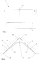
- the sealing element 1 shown in the drawing has an injection-molded plastic part 2 which is L-shaped or Z-shaped in cross section.
- the top view according to Fig. 2 shows that this plastic injection molded part 2 with a rounding 3 is adapted to the shape of a corner of a shower tray, a bathtub or the like.
- the plastic injection-molded part 2 is injection-molded with its narrow sides 5,6 facing away from the corner onto a blank 7,8 of a sealing membrane. These blanks 7, 8 end with the narrow edges 5, 6 on the underside.
- an angle profile 9 protruding on the top is provided in the exemplary embodiment.
- Each leg 10, 11 of the angle profile 9 overlaps with the corresponding blank 7, 8, the legs 10, 11 each being arranged between the wall 4 and the corresponding blank 5, 6.
- the profile 9 as well as the blank 7, 8 connected to the legs 10, 11 each close in one plane.
- Fig. 2 further shows that in the plan view the legs pointing away from the corner each terminate in flat ends 14, 15 on the respective blank 5, 6.
- the ends 14, 15 of the injection-molded plastic part each have a protrusion 16, 17 which ends at the bottom with the injection-molded plastic part 2.
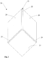
- Figure 3 shows a further embodiment of a sealing element 20 for an inside or outside corner.
- the plastic injection-molded part 21 has three profiles 22-24, each with an L-shaped cross section. Tension these profiles 22-24 the axes of a spatial coordinate system, as it were, and are perpendicular to one another in the exemplary embodiment of the sealing element 20. Other angles are also possible without any problems.
- the legs of the profiles 22-24 are molded directly onto three blanks 25-27. This provides a prefabricated sealing element for an inside or outside corner.
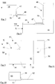
- Sealing element 30 is used to seal a protruding or recessed corner of a construction element.
- the molded plastic part 32 molded onto the blank 31 has a largely dimensionally stable corner 33 protruding from the blank 31.
- the dimensional stability of the corner 33 is achieved by a comparatively large material thickness, compare Figure 6 .
- the one in the Figures 4-6 The lower-side approach of two strips 34, 35 further stiffens the corner 33, even if these are of significantly less material thickness.
- the strips 34, 35 are connected by a rounded section 36 of the plastic injection-molded part 32.
- the strips 34, 35 and the section 36 connecting the strips 34, 35 are weak in material and thus very elastic, so that there is also an irregularly shaped edge of a corner of a construction element can be sealed perfectly.
- the corner 33 is continued in two wing-like projections 37, 38 which overlap with the blank 31 on its inside 39.
- another strip 40 of the injection-molded plastic part 32 follows the fillet 41 of the corner 33.
- the blank 31 therefore also follows this fillet 41 in an upper region 42.
- the strip 40 On the inside of the corner, the strip 40 still overlaps with a section 43 of the blank 31.
- An adhesive strip 44 arranged above it still simplifies the handling of the sealing element 30.
- the sealing element 45 serves to seal a corner, for example a brickwork rising above a floor.
- an L-shaped section 46 of a blank 51 lying on the floor will then encompass the corner of the masonry.
- two further sections 47, 48, connected in one piece with the L-shaped section 46, open vertically and the vertically rising edge of the wall corner is thus reliably sealed.
- plastic injection-molded part 49 which connects a lower edge of section 47 to the edge of L-shaped section 46 at an angle of 90 ° here.
- the plastic injection-molded part 49 further enforces the right angle between the sections 47, 48 of the blank 51 with a bend 50.
- the embodiment of a sealing element 53 according to. the Figures 9 to 11 has two blanks 54, 55 which are connected to one another by a plastic injection-molded part 56.
- a first section 62 of the blank 55, lying in one plane with the blank 54, is connected to the latter by a web 57 of the plastic injection-molded part 56.
- a second section 58 of the blank 55 is angled at right angles to form a rounding of a small radius.
- a third section 60 connects to section 58 with an arch 59. This third section 60 is further connected to the blank 54 via a second web 61 of the plastic injection-molded part 56, forming a right angle.
- the element 67 of the injection-molded plastic part 68 that forms the blank 66 is perpendicular to the plane of the drawing Figure 12 .
- a web 69 of the injection-molded plastic part 68 merely connects the edges of the blank 65 Front view according to Figure 12 an L-shaped area of the blank which lies in a plane formed by the three quarters 70-72.
- the upper right quarter 74 protrudes into the plane of the drawing through the element 67 of the plastic injection-molded part 68, compare Figure 14 .
- an approximately S-arcuate course of the blank 66 according to FIG Figure 14 one.
- Cutting 56 Plastic molded part 57. web 58. section 59. bow 60. section 61. web 62. section 63. 64. 65. Sealing element 66. Cutting 67. element 68. Plastic molded part 69. web 70. quarter 71. quarter 72. quarter 73. quarter
Landscapes
- Engineering & Computer Science (AREA)
- Architecture (AREA)
- Health & Medical Sciences (AREA)
- Public Health (AREA)
- Physics & Mathematics (AREA)
- Electromagnetism (AREA)
- Civil Engineering (AREA)
- Structural Engineering (AREA)
- Epidemiology (AREA)
- General Health & Medical Sciences (AREA)
- Building Environments (AREA)
- Injection Moulding Of Plastics Or The Like (AREA)
Description
- Die Erfindung betrifft ein Dichtungselement für Baufugen, Übergänge, Ecken oder dergleichen Isolations-Fehlstellen, die einer räumlichen Abdichtung bedürfen, und das wenigstens einen Zuschnitt einer Dichtungsbahn aufweist.
- Dichtungsbahnen sind in vielfältigen Ausführungsformen bekannt und bewährt. Zumeist handelt es sich um einen Folienverbund, gegebenenfalls auch um kaschierte Vliese, die je nach Verwendungszweck dampfhemmend oder dampfsperrend sein können. Solche Dichtungsbahnen finden Verwendung bei der Abdichtung von Baufugen, den Anschlüssen von Fenstern oder sanitären Einrichtungen an ein Mauerwerk oder dergleichen mehr. Die Verwendung derartiger Dichtbahnen ist unproblematisch, solange eine Abdichtung in einer Ebene erfolgt. Problematisch ist hingegen eine Abdichtung von Fehlstellen, die in einem hohen Maße räumlich strukturiert sind. Dies können die Übergänge von beispielsweise runden Ecken von Duschtassen, Badewannen oder dergleichen hin zu einer Wand sein, die Ecken aufeinanderstoßender Wände, insbesondere die Ecken von Wänden mit einem Fußboden oder einer Decke und dergleichen mehr.
- Vor diesem Hintergrund macht die Erfindung es sich zur Aufgabe, ein Dichtungselement der eingangs genannten Art zur Verfügung zu stellen, das gleichsam vorkonfektioniert einem Handwerker die Möglichkeit einer schnellen und sicheren Abdichtung derartiger räumlicher Isolations-Fehlstellen ermöglicht.
- Gelöst wird diese technische Problematik bei einem wenigstens einen Zuschnitt einer Dichtungsbahn aufweisenden Dichtungselement für Baufugen, Übergänge, Ecken oder dergleichen Isolations-Fehlstellen, die einer räumlichen Abdichtung bedürfen, gemäß des Anspruchs 1 durch die Maßnahme, dass der wenigstens eine Zuschnitt durch wenigstens ein angespritztes Kunststoffspritzteil eine die Fehlstelle abdeckende, räumliche Gestalt erhält.
- Die Dichtungsbahn kann prinzipiell herkömmlichen Dichtungsbahnen entsprechen. Einer und insbesondere mehrere Zuschnitte dieser Dichtungsbahn, zumeist von rechteckig-quadratischer Form, werden durch das Kunststoffspritzteil in eine räumliche Gestalt gebracht, die geeignet ist, die angesprochenen Isolations-Fehlstellen zu überdecken.
- In vorteilhafterweise ist damit einem Handwerker die Möglichkeit gegeben, Isolations-Fehlstellen in einfacher Form sicher abzudichten. An das Dichtungselement nach der Erfindung können sich dann weitere Dichtungsbahnen, vorzugsweise überlappend, anschließen.
- Ist insbesondere daran gedacht, Isolations-Fehlstellen durch ein angespritztes Kunststoffspritzteil auszufüllen, hat es sich als vorteilhaft erwiesen, wenn dieses Kunststoffspritzteil gummielastisch ist. Hierdurch werden Toleranzen in einfacher Weise ausgeglichen.
- Bevorzugt wird dabei ein Kunststoffspritzteil aus einem TPE, einem thermoplastischen Elastomer. Dessen Shorehärte kann insbesondere 50 oder weniger betragen.
- Überraschenderweise hat es sich gezeigt, dass es durchaus möglich ist, ein solches thermoplastisches Elastomer an eine Dichtungsbahn anzuspritzen.
- Dabei wird grundsätzlich derart vorgegangen, dass die Dichtungsbahn in ein Spritzwerkzeug eingelegt wird und dann das Kunststoffspritzteil angespritzt wird.
- In konstruktiver Ausgestaltung kann daran gedacht sein, dass das Kunststoffspritzteil wenigstens zwei Schmalseiten zweier sich in zwei verschiedenen Ebenen erstreckenden Zuschnitte verbindet. Sind zwei Zuschnitte vorgesehen, handelt es sich insbesondere um ein Dichtungselement für beispielsweise aufeinanderstoßende Wände. Sind drei Zuschnitte vorgesehen, so dient ein solches Dichtungselement der Abdichtung der von zwei Wänden und einer Decke bzw. einem Boden aufgespannten Ecke.
- Dabei kann grundsätzlich das Kunststoffspritzteil mit einer Schmalseite eines Zuschnittes überlappen oder diese beidseits einfassend angespritzt sein.
- Sofern das Kunststoffspritzteil räumlich ausgebildet die Fehlstelle abdichtend überdecken und/oder ausfüllen soll, ist der Formenvielfalt kaum eine Grenze gesetzt. Einfache Blöcke, Keile oder dergleichen sind möglich wie unterschiedlichste, die Zuschnitte verbindende Profile.
- Insbesondere dann kann daran gedacht sein, dass das Kunststoffspritzteil wenigstens einen formstabilen Abschnitt aufweist, bspw. einen eine Ecke ausfüllenden oder umgreifenden Abschnitt.
- Daneben kann das Kunststoffformteil einen einen Einschnitt des Zuschnittes schließenden Abschnitt aufweisen.
- Das Dichtungselement wird anhand der Zeichnung näher erläutert, in der lediglich Ausführungsbeispiele schematisch und nicht maßstabsgerecht dargestellt sind. Insbesondere sind die Materialstärken deutlich überhöht dargestellt. In der Zeichnung zeigt:
- Fig. 1:
- in einer Frontansicht ein erstes Ausführungsbeispiel eines Dichtungselementes,
- Fig. 2:
- eine Draufsicht auf das Dichtungselement nach
Figur 1 , - Fig. 3:
- ein Dichtungselement für das Abdichten einer Innen- und/oder Außenecke,
- Fig. 4:
- eine Draufsicht auf ein weiteres Ausführungsbeispiel,
- Fig. 5:
- eine Ansicht gemäß des Pfeils V in
Figur 4 , - Fig. 6:
- eine Ansicht gemäß des Pfeils VI in
Figur 4 , - Fig. 7:
- eine Seitenansicht eines weiteren Dichtungselements,
- Fig. 8:
- eine Draufsicht auf das Dichtungselement nach
Figur 7 gemäß des Pfeils VIII inFigur 7 , - Fig. 9:
- eine Seitenansicht eines weiteren Ausführungsbeispiels,
- Fig. 10:
- eine Draufsicht gemäß des Pfeils X in
Figur 9 , - Fig. 11:
- eine seitliche Darstellung gemäß des Pfeils XI in
Figur 9 , - Fig. 12:
- eine frontseitige Ansicht eines Dichtungselementes,
- Fig. 13:
- eine seitliche Darstellung gemäß des Pfeils XIII in
Figur 12 und - Fig. 14:
- eine Draufsicht gemäß des Pfeils XIV in
Figur 12 . - Das in den
Figuren 1 und 2 der Zeichnung dargestellte Dichtungselement 1, ein Wandanschlusselement, weist ein in einem Querschnitt L-förmiges oder Z-förmiges Kunststoffspritzteil 2 auf. Die Draufsicht gemäßFig. 2 zeigt auf, dass dieses Kunststoffspritzteil 2 mit einer Abrundung 3 an die Form einer Ecke einer Duschtasse, einer Badewanne oder dergl. angepasst ist. Für den Übergang einer solchen Ecke einer Duschtasse, einer Badewanne oder dergl. auf eine angedeutete Wand 4 ist das Kunststoffspritzteil 2 mit seinen von der Ecke abgewandten Schmalseiten 5,6 jeweils an einen Zuschnitt 7,8 einer Dichtungsbahn angespritzt. Diese Zuschnitte 7,8 schließt dabei unterseitig mit den Schmalkanten 5,6 ab. - Einstückig mit dem Kunststoffspritzteil 2 ist ein oberseitig vorstehendes Winkelprofil 9 bei dem Ausführungsbeispiel vorgesehen. Jeder Schenkel 10,11 des Winkelprofils 9 überlappt mit dem entsprechenden Zuschnitt 7,8, wobei die Schenkel 10,11 jeweils zwischen der Wand 4 und dem entsprechenden Zuschnitt 5,6 angeordnet sind. Oberseitig schließen das Profil 9 sowie jeweils der an die Schenkel 10,11 angebundene Zuschnitt 7,8 in einer Ebene ab.
-
Fig. 2 zeigt weiter auf, dass in der Draufsicht die von der Ecke wegweisenden Schenkel jeweils in flachen Enden 14,15 auf dem jeweiligen Zuschnitt 5,6 auslaufen. Dabei stehen den Enden 14,15 des Kunststoffspritzteils jeweils ein Überstand 16,17 noch vor, der jeweils unterseitig mit dem Kunststoffspritzteil 2 abschließt. -
Figur 3 zeigt ein weiteres Ausführungsbeispiel eines Dichtungselementes 20 für eine Innen- oder Außenecke. - Das Kunststoffspritzteil 21 weist drei jeweils im Querschnitt L-förmige Profile 22-24 auf. Diese Profile 22-24 spannen gleichsam die Achsen eines räumlichen Koordinatensystems auf und stehen bei dem Ausführungsbeispiel des Dichtungselements 20 senkrecht aufeinander. Andere Winkel sind problemlos gleichfalls möglich.
- Die Schenkel der Profile 22-24 sind unmittelbar an drei Zuschnitte 25-27 angespritzt. Hierdurch erhält man ein vorkonfektioniertes Dichtungselement für eine Innen- oder Außenecke.
- Das anhand der
Figuren 4-6 erläuterte Dichtungselement 30 dient der Abdichtung einer vorspringenden oder zurückgenommenen Ecke eines Konstruktionselementes. Hierzu weist das an den Zuschnitt 31 angespritzte Kunststoffformteil 32 eine dem Zuschnitt 31 vorstehende, weitgehend formstabile Ecke 33 auf. Die Formstabilität der Ecke 33 wird durch eine vergleichsweise große Materialstärke erreicht, vergleicheFigur 6 . Der in denFiguren 4-6 unterseitige Ansatz zweier Streifen 34,35 steift die Ecke 33 weiter aus, auch wenn diese von deutlich geringerer Materialstärke sind. Verbunden sind die Streifen 34,35 durch einen abgerundeten Abschnitt 36 des Kunststoffspritzteils 32. Die Streifen 34,35 sowie der die Streifen 34,35 verbindende Abschnitt 36 sind materialschwach und damit sehr elastisch, so dass sich auch eine unregelmäßig ausgebildete Kante einer Ecke eines Konstruktionselementes bestens abdichten lässt. - Die Ecke 33 setzt sich in zwei flügelartigen Ansätzen 37,38 fort, die mit dem Zuschnitt 31 auf dessen Innenseite 39 überlappen. Oberseitig der Ecke 33 folgt ein weiterer Streifen 40 des Kunststoffspritzteils 32 der Ausrundung 41 der Ecke 33. Von daher folgt auch der Zuschnitt 31 in einem oberen Bereich 42 dieser Ausrundung 41.
- Der Streifen 40 überlappt eckeninnenseitig noch mit einem Abschnitt 43 des Zuschnitts 31. Ein darüber noch angeordneter Klebestreifen 44 vereinfacht noch die Handhabung des Dichtungselements 30.
- Auch das Dichtungselement 45 gemäß den
Figuren 7 und 8 dient der Abdichtung einer Ecke, beispielsweise eines über einem Fußboden aufgehenden Mauerwerkes. Bei dieser Verwendung bleibend wird dann ein L-förmiger Abschnitt 46 eines Zuschnitts 51 auf dem Boden liegend die Ecke des Mauerwerks umgreifen. Von diesem L-förmigen Abschnitt 46 gehen zwei weitere Abschnitte 47,48, einstückig mit dem L-förmigen Abschnitt 46 verbunden, vertikal auf und wird so die vertikal aufgehende Kante der Mauerecke sicher abgedichtet. - Hierzu bedarf es lediglich eines Kunststoffspritzteils 49, das eine untere Kante des Abschnitts 47 mit der Kante des L-förmigen Abschnitts 46 unter einem Winkel von hier 90° verbindet. Das Kunststoffspritzteil 49 erzwingt weiter mit einer Abwinklung 50 den rechten Winkel zwischen den Abschnitten 47,48 des Zuschnitts 51.
- Das Ausführungsbeispiel eines Dichtungselementes 53 gem. den
Figuren 9 bis 11 weist zwei Zuschnitte 54,55 auf, die durch ein Kunststoffspritzteil 56 miteinander verbunden sind. Ein erster Abschnitt 62 des Zuschnitts 55 ist in einer Ebene mit dem Zuschnitt 54 liegend durch einen Steg 57 des Kunststoffspritzteils 56 mit diesem verbunden. Ein zweiter Abschnitt 58 des Zuschnitts 55 ist unter Ausbildung einer Rundung von geringem Radius in einem rechten Winkel abgewinkelt. Mit einem Bogen 59 schließt ein dritter Abschnitt 60 an den Abschnitt 58 an. Dieser dritte Abschnitt 60 ist über einen zweiten Steg 61 des Kunststoffspritzteils 56 unter Ausbildung eines rechten Winkels mit dem Zuschnitt 54 weiter verbunden. - Bei dem Ausführungsbeispiel eines Dichtungselements 65 gemäß den
Figuren 12-13 steht das dem Zuschnitt 66 formgebende Element 67 des Kunststoffspritzteils 68 senkrecht zur Zeichenebene derFigur 12 . Ein Steg 69 des Kunststoffspritzteils 68 verbindet lediglich die Ränder des Zuschnitts 65. Aufgrund dieser Maßnahmen ergibt sich in einer Frontansicht gemäßFigur 12 ein L-förmiger Bereich des Zuschnittes, der in einer Ebene liegt, ausgebildet durch die drei Viertel 70-72. Durch das Element 67 des Kunststoffspritzteils 68 verspringt bei dem Ausführungsbeispiel das obere rechte Viertel 74 in die Zeichenebene, vergleicheFigur 14 . Dabei stellt sich, abhängig von der Größe des Elements 67 des Kunststoffspritzteils 68, ein etwa S-bogenförmiger Verlauf des Zuschnitts 66 gemäßFigur 14 ein. - Vergleichbares gilt für den Übergang zwischen dem oberen, rechten Viertel 73 und dem unteren rechten Viertel 72 des Zuschnitts 66.
-
1. Dichtungselement 27. Zuschnitt 2. Kunststoffspritzteil 28. 3. Abrundung 29. 4. Wand 30. Dichtungselement 5. Schmalseite 31. Zuschnitt 6. Schmalseite 32. Kunststoffspritzteil 7. Zuschnitt 33. Ecke 8. Zuschnitt 34. Streifen 9. Winkelprofil 35. Streifen 10. Schenkel 36. Abschnitt 11. Schenkel 37. Ansatz 12. Schenkel 38. Ansatz 13. Schenkel 39. Innenseite 14. Ende 40. Streifen 15. Ende 41. Ausrundung 16. 42. Bereich 17. 43. Abschnitt 18. 44. Klebestreifen 19. 45. Dichtungselement 20. Dichtungselement 46. Abschnitt 21. Kunststoffspritzteil 47. Abschnitt 22. Profil 48. Abschnitt 23. Profil 49. Kunststoffspritzteil 24. Profil 50. Abwinklung 25. Zuschnitt 51. Zuschnitt 26. Zuschnitt 52. 53. Dichtungselement 54. Zuschnitt 55. Zuschnitt 56. Kunststoffspritzteil 57. Steg 58. Abschnitt 59. Bogen 60. Abschnitt 61. Steg 62. Abschnitt 63. 64. 65. Dichtungselement 66. Zuschnitt 67. Element 68. Kunststoffspritzteil 69. Steg 70. Viertel 71. Viertel 72. Viertel 73. Viertel
Claims (9)
- Wenigstens einen Zuschnitt einer Dichtungsbahn aufweisendes Dichtungselement für Baufugen, Übergänge, Ecken oder dergleichen Isolations-Fehlstellen, die einer räumlichen Abdichtung bedürfen, dadurch gekennzeichnet, dass der wenigstens eine Zuschnitt durch wenigstens ein angespritztes Kunststoffspritzteil eine die Fehlstelle abdeckende, räumliche Gestalt erhält.
- Dichtungselement nach Anspruch 1, dadurch gekennzeichnet, dass das Kunststoffspritzteil gummielastisch ist.
- Dichtungselement nach einem oder mehreren der vorangehenden Ansprüche, dadurch gekennzeichnet, dass das Kunststoffspritzteil aus einem TPE besteht.
- Dichtungselement nach einem oder mehreren der vorangehenden Ansprüche, dadurch gekennzeichnet, dass die Shorehärte des Kunststoffspritzteils 50 oder weniger beträgt.
- Dichtungselement nach einem oder mehreren der vorangehenden Ansprüche, dadurch gekennzeichnet, dass das Kunststoffspritzteil wenigstens zwei Schmalseiten zweier sich in zwei verschiedenen Ebenen erstreckenden Zuschnitte verbindet.
- Dichtungselement nach einem oder mehreren der vorangehenden Ansprüche, dadurch gekennzeichnet, dass das Kunststoffspritzteil mit einer Schmalseite eines Zuschnitts überlappend oder diese beidseits einfassend angespritzt ist.
- Dichtungselement nach einem oder mehreren der vorangehenden Ansprüche, dadurch gekennzeichnet, dass das Kunststoffspritzteil räumlich ausgebildet die Fehlstelle abdichtend überdeckt und/oder ausfüllt.
- Dichtungselement nach einem oder mehreren der vorangehenden Ansprüche, dadurch gekennzeichnet, dass das Kunststoffspritzteil wenigstens einen formstabilen Abschnitt aufweist.
- Dichtungselement nach einem oder mehreren der vorangehenden Ansprüche, dadurch gekennzeichnet, dass das Kunststoffformteil einen einen Einschnitt des Zuschnittes schließenden Abschnitt aufweist.
Applications Claiming Priority (1)
| Application Number | Priority Date | Filing Date | Title |
|---|---|---|---|
| DE102015008095.4A DE102015008095A1 (de) | 2015-06-25 | 2015-06-25 | Dichtungselement |
Publications (2)
| Publication Number | Publication Date |
|---|---|
| EP3109369A1 EP3109369A1 (de) | 2016-12-28 |
| EP3109369B1 true EP3109369B1 (de) | 2020-09-30 |
Family
ID=56567331
Family Applications (1)
| Application Number | Title | Priority Date | Filing Date |
|---|---|---|---|
| EP16001419.7A Active EP3109369B1 (de) | 2015-06-25 | 2016-06-24 | Dichtungselement |
Country Status (3)
| Country | Link |
|---|---|
| EP (1) | EP3109369B1 (de) |
| DE (1) | DE102015008095A1 (de) |
| DK (1) | DK3109369T3 (de) |
Family Cites Families (3)
| Publication number | Priority date | Publication date | Assignee | Title |
|---|---|---|---|---|
| DE20121477U1 (de) * | 2001-07-13 | 2002-10-02 | Wedi, Stephan, 48282 Emsdetten | Flexibles Dichtungsband für Badewannen und Duschtassen |
| DE20215528U1 (de) * | 2002-10-09 | 2003-01-02 | Wirz, Peter, 53721 Siegburg | Dichtungsband |
| EP2082674A1 (de) * | 2008-01-22 | 2009-07-29 | Trelleborg Building Systems AB | Wasserdichtes Dichtungsprofil |
-
2015
- 2015-06-25 DE DE102015008095.4A patent/DE102015008095A1/de not_active Withdrawn
-
2016
- 2016-06-24 EP EP16001419.7A patent/EP3109369B1/de active Active
- 2016-06-24 DK DK16001419.7T patent/DK3109369T3/da active
Non-Patent Citations (1)
| Title |
|---|
| None * |
Also Published As
| Publication number | Publication date |
|---|---|
| DK3109369T3 (da) | 2020-11-09 |
| DE102015008095A1 (de) | 2016-12-29 |
| EP3109369A1 (de) | 2016-12-28 |
Similar Documents
| Publication | Publication Date | Title |
|---|---|---|
| DE10233731A1 (de) | Anordnung von Bauteilen mit Verbindungselementen | |
| DE19520723C2 (de) | Schalungselement | |
| DE202013011966U1 (de) | Abdichtungsbahn | |
| WO2005090698A1 (de) | Vakuum-isolations-paneel und verfahren zu dessen herstellung | |
| EP0748179A1 (de) | Zarge zur herstellung von wandabschlüssen | |
| EP3109369B1 (de) | Dichtungselement | |
| CH713242A2 (de) | Dichtelement zur Abdichtung einer Wannenecke gegenüber einer Baukonstruktion und Verfahren dafür. | |
| DE102017107375A1 (de) | Dichtband, Dichtecke und Set bestehend aus Dichtband und Dichtecke | |
| DE19514165A1 (de) | Bauelement sowie damit hergestellte Wandverkleidung | |
| DE1989172U (de) | Hohlplatte zur erstellung von wandverkleidungen, einschubdecken od. dgl. | |
| DE19725734C1 (de) | Doppelbodenplatte mit plattenförmigem Belag und Verfahren zu deren Herstellung | |
| DE2856461A1 (de) | Einbauvorrichtung zur halterung eines plattenfoermigen einbauelements | |
| EP0615033B1 (de) | Wand aus Balken oder dergleichen mit einer Abdichtung | |
| DE102011007873B4 (de) | Dichtklebeband | |
| DE10302961B4 (de) | Wandabschlussleiste | |
| EP0307552A1 (de) | Arbeitsplatteneinheit | |
| EP0437660A1 (de) | Randstreifen aus Linoleum | |
| EP4141196A1 (de) | Systemteil | |
| EP0653526A2 (de) | Abdichtelement und Verfahren zu seiner Herstellung | |
| DE102023103182A1 (de) | Dichtecke | |
| DE29815633U1 (de) | Laibungslehre für Wandöffnungen | |
| DE202010016541U1 (de) | Werkzeug | |
| DE29810180U1 (de) | Vorrichtung zur Ausbildung eines Anschlußüberganges zwischen zwei rechtwinklig aneinander angrenzenden Flächen mit starren Belägen | |
| DE202013008960U1 (de) | Anordnung von Bauelementen aus EPS zur Bildung von Wänden | |
| DE9015980U1 (de) | Dekorplatte mit Kunststoff-Abschlußprofil |
Legal Events
| Date | Code | Title | Description |
|---|---|---|---|
| PUAI | Public reference made under article 153(3) epc to a published international application that has entered the european phase |
Free format text: ORIGINAL CODE: 0009012 |
|
| STAA | Information on the status of an ep patent application or granted ep patent |
Free format text: STATUS: THE APPLICATION HAS BEEN PUBLISHED |
|
| AK | Designated contracting states |
Kind code of ref document: A1 Designated state(s): AL AT BE BG CH CY CZ DE DK EE ES FI FR GB GR HR HU IE IS IT LI LT LU LV MC MK MT NL NO PL PT RO RS SE SI SK SM TR |
|
| AX | Request for extension of the european patent |
Extension state: BA ME |
|
| STAA | Information on the status of an ep patent application or granted ep patent |
Free format text: STATUS: REQUEST FOR EXAMINATION WAS MADE |
|
| 17P | Request for examination filed |
Effective date: 20170622 |
|
| GRAP | Despatch of communication of intention to grant a patent |
Free format text: ORIGINAL CODE: EPIDOSNIGR1 |
|
| STAA | Information on the status of an ep patent application or granted ep patent |
Free format text: STATUS: GRANT OF PATENT IS INTENDED |
|
| INTG | Intention to grant announced |
Effective date: 20200330 |
|
| GRAS | Grant fee paid |
Free format text: ORIGINAL CODE: EPIDOSNIGR3 |
|
| GRAA | (expected) grant |
Free format text: ORIGINAL CODE: 0009210 |
|
| STAA | Information on the status of an ep patent application or granted ep patent |
Free format text: STATUS: THE PATENT HAS BEEN GRANTED |
|
| AK | Designated contracting states |
Kind code of ref document: B1 Designated state(s): AL AT BE BG CH CY CZ DE DK EE ES FI FR GB GR HR HU IE IS IT LI LT LU LV MC MK MT NL NO PL PT RO RS SE SI SK SM TR |
|
| REG | Reference to a national code |
Ref country code: CH Ref legal event code: EP Ref country code: GB Ref legal event code: FG4D Free format text: NOT ENGLISH |
|
| REG | Reference to a national code |
Ref country code: AT Ref legal event code: REF Ref document number: 1318928 Country of ref document: AT Kind code of ref document: T Effective date: 20201015 |
|
| REG | Reference to a national code |
Ref country code: DE Ref legal event code: R096 Ref document number: 502016011287 Country of ref document: DE |
|
| REG | Reference to a national code |
Ref country code: IE Ref legal event code: FG4D Free format text: LANGUAGE OF EP DOCUMENT: GERMAN |
|
| REG | Reference to a national code |
Ref country code: DK Ref legal event code: T3 Effective date: 20201103 |
|
| REG | Reference to a national code |
Ref country code: CH Ref legal event code: NV Representative=s name: SIVIER | BREVETS, MARQUES, DESIGNS, CH |
|
| REG | Reference to a national code |
Ref country code: NO Ref legal event code: T2 Effective date: 20200930 |
|
| REG | Reference to a national code |
Ref country code: SE Ref legal event code: TRGR |
|
| PG25 | Lapsed in a contracting state [announced via postgrant information from national office to epo] |
Ref country code: GR Free format text: LAPSE BECAUSE OF FAILURE TO SUBMIT A TRANSLATION OF THE DESCRIPTION OR TO PAY THE FEE WITHIN THE PRESCRIBED TIME-LIMIT Effective date: 20201231 Ref country code: BG Free format text: LAPSE BECAUSE OF FAILURE TO SUBMIT A TRANSLATION OF THE DESCRIPTION OR TO PAY THE FEE WITHIN THE PRESCRIBED TIME-LIMIT Effective date: 20201230 Ref country code: FI Free format text: LAPSE BECAUSE OF FAILURE TO SUBMIT A TRANSLATION OF THE DESCRIPTION OR TO PAY THE FEE WITHIN THE PRESCRIBED TIME-LIMIT Effective date: 20200930 Ref country code: HR Free format text: LAPSE BECAUSE OF FAILURE TO SUBMIT A TRANSLATION OF THE DESCRIPTION OR TO PAY THE FEE WITHIN THE PRESCRIBED TIME-LIMIT Effective date: 20200930 |
|
| PG25 | Lapsed in a contracting state [announced via postgrant information from national office to epo] |
Ref country code: LV Free format text: LAPSE BECAUSE OF FAILURE TO SUBMIT A TRANSLATION OF THE DESCRIPTION OR TO PAY THE FEE WITHIN THE PRESCRIBED TIME-LIMIT Effective date: 20200930 Ref country code: RS Free format text: LAPSE BECAUSE OF FAILURE TO SUBMIT A TRANSLATION OF THE DESCRIPTION OR TO PAY THE FEE WITHIN THE PRESCRIBED TIME-LIMIT Effective date: 20200930 |
|
| REG | Reference to a national code |
Ref country code: NL Ref legal event code: MP Effective date: 20200930 |
|
| REG | Reference to a national code |
Ref country code: LT Ref legal event code: MG4D |
|
| PG25 | Lapsed in a contracting state [announced via postgrant information from national office to epo] |
Ref country code: CZ Free format text: LAPSE BECAUSE OF FAILURE TO SUBMIT A TRANSLATION OF THE DESCRIPTION OR TO PAY THE FEE WITHIN THE PRESCRIBED TIME-LIMIT Effective date: 20200930 Ref country code: PT Free format text: LAPSE BECAUSE OF FAILURE TO SUBMIT A TRANSLATION OF THE DESCRIPTION OR TO PAY THE FEE WITHIN THE PRESCRIBED TIME-LIMIT Effective date: 20210201 Ref country code: RO Free format text: LAPSE BECAUSE OF FAILURE TO SUBMIT A TRANSLATION OF THE DESCRIPTION OR TO PAY THE FEE WITHIN THE PRESCRIBED TIME-LIMIT Effective date: 20200930 Ref country code: SM Free format text: LAPSE BECAUSE OF FAILURE TO SUBMIT A TRANSLATION OF THE DESCRIPTION OR TO PAY THE FEE WITHIN THE PRESCRIBED TIME-LIMIT Effective date: 20200930 Ref country code: EE Free format text: LAPSE BECAUSE OF FAILURE TO SUBMIT A TRANSLATION OF THE DESCRIPTION OR TO PAY THE FEE WITHIN THE PRESCRIBED TIME-LIMIT Effective date: 20200930 Ref country code: LT Free format text: LAPSE BECAUSE OF FAILURE TO SUBMIT A TRANSLATION OF THE DESCRIPTION OR TO PAY THE FEE WITHIN THE PRESCRIBED TIME-LIMIT Effective date: 20200930 Ref country code: NL Free format text: LAPSE BECAUSE OF FAILURE TO SUBMIT A TRANSLATION OF THE DESCRIPTION OR TO PAY THE FEE WITHIN THE PRESCRIBED TIME-LIMIT Effective date: 20200930 |
|
| PG25 | Lapsed in a contracting state [announced via postgrant information from national office to epo] |
Ref country code: ES Free format text: LAPSE BECAUSE OF FAILURE TO SUBMIT A TRANSLATION OF THE DESCRIPTION OR TO PAY THE FEE WITHIN THE PRESCRIBED TIME-LIMIT Effective date: 20200930 Ref country code: AL Free format text: LAPSE BECAUSE OF FAILURE TO SUBMIT A TRANSLATION OF THE DESCRIPTION OR TO PAY THE FEE WITHIN THE PRESCRIBED TIME-LIMIT Effective date: 20200930 Ref country code: PL Free format text: LAPSE BECAUSE OF FAILURE TO SUBMIT A TRANSLATION OF THE DESCRIPTION OR TO PAY THE FEE WITHIN THE PRESCRIBED TIME-LIMIT Effective date: 20200930 Ref country code: IS Free format text: LAPSE BECAUSE OF FAILURE TO SUBMIT A TRANSLATION OF THE DESCRIPTION OR TO PAY THE FEE WITHIN THE PRESCRIBED TIME-LIMIT Effective date: 20210130 |
|
| PG25 | Lapsed in a contracting state [announced via postgrant information from national office to epo] |
Ref country code: SK Free format text: LAPSE BECAUSE OF FAILURE TO SUBMIT A TRANSLATION OF THE DESCRIPTION OR TO PAY THE FEE WITHIN THE PRESCRIBED TIME-LIMIT Effective date: 20200930 |
|
| REG | Reference to a national code |
Ref country code: DE Ref legal event code: R097 Ref document number: 502016011287 Country of ref document: DE |
|
| PLBE | No opposition filed within time limit |
Free format text: ORIGINAL CODE: 0009261 |
|
| STAA | Information on the status of an ep patent application or granted ep patent |
Free format text: STATUS: NO OPPOSITION FILED WITHIN TIME LIMIT |
|
| 26N | No opposition filed |
Effective date: 20210701 |
|
| PG25 | Lapsed in a contracting state [announced via postgrant information from national office to epo] |
Ref country code: SI Free format text: LAPSE BECAUSE OF FAILURE TO SUBMIT A TRANSLATION OF THE DESCRIPTION OR TO PAY THE FEE WITHIN THE PRESCRIBED TIME-LIMIT Effective date: 20200930 |
|
| PG25 | Lapsed in a contracting state [announced via postgrant information from national office to epo] |
Ref country code: MC Free format text: LAPSE BECAUSE OF FAILURE TO SUBMIT A TRANSLATION OF THE DESCRIPTION OR TO PAY THE FEE WITHIN THE PRESCRIBED TIME-LIMIT Effective date: 20200930 |
|
| PG25 | Lapsed in a contracting state [announced via postgrant information from national office to epo] |
Ref country code: LU Free format text: LAPSE BECAUSE OF NON-PAYMENT OF DUE FEES Effective date: 20210624 |
|
| PG25 | Lapsed in a contracting state [announced via postgrant information from national office to epo] |
Ref country code: IE Free format text: LAPSE BECAUSE OF NON-PAYMENT OF DUE FEES Effective date: 20210624 |
|
| PG25 | Lapsed in a contracting state [announced via postgrant information from national office to epo] |
Ref country code: IS Free format text: LAPSE BECAUSE OF FAILURE TO SUBMIT A TRANSLATION OF THE DESCRIPTION OR TO PAY THE FEE WITHIN THE PRESCRIBED TIME-LIMIT Effective date: 20210130 |
|
| PG25 | Lapsed in a contracting state [announced via postgrant information from national office to epo] |
Ref country code: HU Free format text: LAPSE BECAUSE OF FAILURE TO SUBMIT A TRANSLATION OF THE DESCRIPTION OR TO PAY THE FEE WITHIN THE PRESCRIBED TIME-LIMIT; INVALID AB INITIO Effective date: 20160624 |
|
| PG25 | Lapsed in a contracting state [announced via postgrant information from national office to epo] |
Ref country code: CY Free format text: LAPSE BECAUSE OF FAILURE TO SUBMIT A TRANSLATION OF THE DESCRIPTION OR TO PAY THE FEE WITHIN THE PRESCRIBED TIME-LIMIT Effective date: 20200930 |
|
| PG25 | Lapsed in a contracting state [announced via postgrant information from national office to epo] |
Ref country code: MK Free format text: LAPSE BECAUSE OF FAILURE TO SUBMIT A TRANSLATION OF THE DESCRIPTION OR TO PAY THE FEE WITHIN THE PRESCRIBED TIME-LIMIT Effective date: 20200930 |
|
| PG25 | Lapsed in a contracting state [announced via postgrant information from national office to epo] |
Ref country code: MT Free format text: LAPSE BECAUSE OF FAILURE TO SUBMIT A TRANSLATION OF THE DESCRIPTION OR TO PAY THE FEE WITHIN THE PRESCRIBED TIME-LIMIT Effective date: 20200930 |
|
| PGFP | Annual fee paid to national office [announced via postgrant information from national office to epo] |
Ref country code: GB Payment date: 20250620 Year of fee payment: 10 Ref country code: DK Payment date: 20250618 Year of fee payment: 10 |
|
| PGFP | Annual fee paid to national office [announced via postgrant information from national office to epo] |
Ref country code: NO Payment date: 20250617 Year of fee payment: 10 |
|
| PGFP | Annual fee paid to national office [announced via postgrant information from national office to epo] |
Ref country code: BE Payment date: 20250617 Year of fee payment: 10 |
|
| PGFP | Annual fee paid to national office [announced via postgrant information from national office to epo] |
Ref country code: FR Payment date: 20250626 Year of fee payment: 10 |
|
| PGFP | Annual fee paid to national office [announced via postgrant information from national office to epo] |
Ref country code: AT Payment date: 20250616 Year of fee payment: 10 |
|
| PGFP | Annual fee paid to national office [announced via postgrant information from national office to epo] |
Ref country code: SE Payment date: 20250618 Year of fee payment: 10 |
|
| REG | Reference to a national code |
Ref country code: CH Ref legal event code: R17 Free format text: ST27 STATUS EVENT CODE: U-0-0-R10-R17 (AS PROVIDED BY THE NATIONAL OFFICE) Effective date: 20251008 |
|
| PGFP | Annual fee paid to national office [announced via postgrant information from national office to epo] |
Ref country code: DE Payment date: 20250826 Year of fee payment: 10 |
|
| PGFP | Annual fee paid to national office [announced via postgrant information from national office to epo] |
Ref country code: IT Payment date: 20250630 Year of fee payment: 10 |
|
| PGFP | Annual fee paid to national office [announced via postgrant information from national office to epo] |
Ref country code: CH Payment date: 20250701 Year of fee payment: 10 |
|
| PG25 | Lapsed in a contracting state [announced via postgrant information from national office to epo] |
Ref country code: TR Free format text: LAPSE BECAUSE OF FAILURE TO SUBMIT A TRANSLATION OF THE DESCRIPTION OR TO PAY THE FEE WITHIN THE PRESCRIBED TIME-LIMIT Effective date: 20200930 |