EP3106417A1 - Steueranordnung und verfahren - Google Patents
Steueranordnung und verfahren Download PDFInfo
- Publication number
- EP3106417A1 EP3106417A1 EP15172270.9A EP15172270A EP3106417A1 EP 3106417 A1 EP3106417 A1 EP 3106417A1 EP 15172270 A EP15172270 A EP 15172270A EP 3106417 A1 EP3106417 A1 EP 3106417A1
- Authority
- EP
- European Patent Office
- Prior art keywords
- elevator
- elevator apparatus
- safety gear
- control arrangement
- sequence
- Prior art date
- Legal status (The legal status is an assumption and is not a legal conclusion. Google has not performed a legal analysis and makes no representation as to the accuracy of the status listed.)
- Granted
Links
- 238000000034 method Methods 0.000 title claims description 9
- 230000001960 triggered effect Effects 0.000 claims abstract description 3
- 230000003213 activating effect Effects 0.000 claims abstract 3
- 238000005259 measurement Methods 0.000 claims description 9
- 238000004891 communication Methods 0.000 claims description 7
- 230000000977 initiatory effect Effects 0.000 claims 1
- 238000012423 maintenance Methods 0.000 abstract description 3
- 238000009434 installation Methods 0.000 description 5
- 230000007423 decrease Effects 0.000 description 2
- 230000004913 activation Effects 0.000 description 1
- 238000004590 computer program Methods 0.000 description 1
- 230000001419 dependent effect Effects 0.000 description 1
- JEIPFZHSYJVQDO-UHFFFAOYSA-N iron(III) oxide Inorganic materials O=[Fe]O[Fe]=O JEIPFZHSYJVQDO-UHFFFAOYSA-N 0.000 description 1
- 239000000725 suspension Substances 0.000 description 1
- 238000005303 weighing Methods 0.000 description 1
Images

Classifications
-
- B—PERFORMING OPERATIONS; TRANSPORTING
- B66—HOISTING; LIFTING; HAULING
- B66B—ELEVATORS; ESCALATORS OR MOVING WALKWAYS
- B66B5/00—Applications of checking, fault-correcting, or safety devices in elevators
- B66B5/02—Applications of checking, fault-correcting, or safety devices in elevators responsive to abnormal operating conditions
- B66B5/16—Braking or catch devices operating between cars, cages, or skips and fixed guide elements or surfaces in hoistway or well
- B66B5/18—Braking or catch devices operating between cars, cages, or skips and fixed guide elements or surfaces in hoistway or well and applying frictional retarding forces
-
- B—PERFORMING OPERATIONS; TRANSPORTING
- B66—HOISTING; LIFTING; HAULING
- B66B—ELEVATORS; ESCALATORS OR MOVING WALKWAYS
- B66B1/00—Control systems of elevators in general
- B66B1/02—Control systems without regulation, i.e. without retroactive action
- B66B1/06—Control systems without regulation, i.e. without retroactive action electric
-
- B—PERFORMING OPERATIONS; TRANSPORTING
- B66—HOISTING; LIFTING; HAULING
- B66B—ELEVATORS; ESCALATORS OR MOVING WALKWAYS
- B66B1/00—Control systems of elevators in general
- B66B1/24—Control systems with regulation, i.e. with retroactive action, for influencing travelling speed, acceleration, or deceleration
- B66B1/28—Control systems with regulation, i.e. with retroactive action, for influencing travelling speed, acceleration, or deceleration electrical
- B66B1/32—Control systems with regulation, i.e. with retroactive action, for influencing travelling speed, acceleration, or deceleration electrical effective on braking devices, e.g. acting on electrically controlled brakes
-
- B—PERFORMING OPERATIONS; TRANSPORTING
- B66—HOISTING; LIFTING; HAULING
- B66B—ELEVATORS; ESCALATORS OR MOVING WALKWAYS
- B66B1/00—Control systems of elevators in general
- B66B1/34—Details, e.g. call counting devices, data transmission from car to control system, devices giving information to the control system
- B66B1/3415—Control system configuration and the data transmission or communication within the control system
- B66B1/3446—Data transmission or communication within the control system
- B66B1/3461—Data transmission or communication within the control system between the elevator control system and remote or mobile stations
-
- B—PERFORMING OPERATIONS; TRANSPORTING
- B66—HOISTING; LIFTING; HAULING
- B66B—ELEVATORS; ESCALATORS OR MOVING WALKWAYS
- B66B5/00—Applications of checking, fault-correcting, or safety devices in elevators
- B66B5/0087—Devices facilitating maintenance, repair or inspection tasks
- B66B5/0093—Testing of safety devices
-
- B—PERFORMING OPERATIONS; TRANSPORTING
- B66—HOISTING; LIFTING; HAULING
- B66B—ELEVATORS; ESCALATORS OR MOVING WALKWAYS
- B66B5/00—Applications of checking, fault-correcting, or safety devices in elevators
- B66B5/02—Applications of checking, fault-correcting, or safety devices in elevators responsive to abnormal operating conditions
- B66B5/04—Applications of checking, fault-correcting, or safety devices in elevators responsive to abnormal operating conditions for detecting excessive speed
- B66B5/044—Mechanical overspeed governors
-
- B—PERFORMING OPERATIONS; TRANSPORTING
- B66—HOISTING; LIFTING; HAULING
- B66B—ELEVATORS; ESCALATORS OR MOVING WALKWAYS
- B66B5/00—Applications of checking, fault-correcting, or safety devices in elevators
- B66B5/02—Applications of checking, fault-correcting, or safety devices in elevators responsive to abnormal operating conditions
- B66B5/16—Braking or catch devices operating between cars, cages, or skips and fixed guide elements or surfaces in hoistway or well
- B66B5/18—Braking or catch devices operating between cars, cages, or skips and fixed guide elements or surfaces in hoistway or well and applying frictional retarding forces
- B66B5/24—Braking or catch devices operating between cars, cages, or skips and fixed guide elements or surfaces in hoistway or well and applying frictional retarding forces by acting on guide ropes or cables
-
- B—PERFORMING OPERATIONS; TRANSPORTING
- B66—HOISTING; LIFTING; HAULING
- B66B—ELEVATORS; ESCALATORS OR MOVING WALKWAYS
- B66B9/00—Kinds or types of lifts in, or associated with, buildings or other structures
-
- B—PERFORMING OPERATIONS; TRANSPORTING
- B66—HOISTING; LIFTING; HAULING
- B66B—ELEVATORS; ESCALATORS OR MOVING WALKWAYS
- B66B2201/00—Aspects of control systems of elevators
Definitions
- This invention relates to a solution for maintaining an elevator and in particularly to safety devices of the elevator.
- an elevator has safety devices for stopping the movement of a falling elevator car.
- These safety devices include an over speed governor which can be located in several alternative locations such as in the elevator hoistway or in a machine room.
- the over speed governor utilizes a rope which moves with the elevator car and which is connected to a safety gear in order to provide an actuating force to the safety gear when needed.
- the over speed governor prevents movement of the rope.
- the rope is connected to a safety gear of an elevator car that moves downwards while the rope is prevented from moving, an actuating force caused by the speed difference is provided to the safety gear. Due to this actuating force, the safety gear starts to brake the elevator car until it comes to a stop.
- Figures 1 and 2 illustrate a safety gear 1.
- Figure 1 illustrates the safety gear 1 and a guide rail 3 from above and Figure 2 mainly from the side.
- the illustrated safety gear 1 is of a sliding type, as it during use in an elevator apparatus 2 slides along a vertical guide rail 3 mounted in an elevator hoistway.
- the elevator apparatus may consist of an elevator car or of a counterweight, however, for simplicity in the illustrated examples only an elevator car is illustrated.
- the illustrated safety gear 1 has a roller shaped force element 4 though alternatively a wedge shaped force element could be in use.
- the force element 4 remains in the position illustrated in Figure 2 , in other words in the lower part of the safety gear 1.
- the guide rail 3 has enough space between the force element 4 and the braking surface 5 facing the force element such that no braking occurs while the safety gear 1 slides along the guide rail 3.
- the upward movement of the force element 4 may be implemented via the shaft 7 for instance.
- the safety gear 1 brakes.
- the force element 4 may be moved downwards via the shaft 7 simultaneously as the elevator apparatus 2 is moved upwards via its drive unit, for instance.
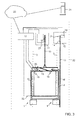
- FIG 3 illustrates an elevator with an elevator apparatus 2.
- This elevator may be provided with one or more of the safety gears 1 illustrated in Figures 1 and 2 for braking the elevator apparatus with the aid of vertical guide rails 3.
- safety gears 1 illustrated in Figures 1 and 2 for braking the elevator apparatus with the aid of vertical guide rails 3.
- the elevator apparatus 2 is provided with a drive unit 11 for driving the elevator apparatus 2 upwards and downwards.
- a drive unit 11 may include an electric motor, a frequency converter and a traction pulley pulling a hoisting rope 10, for instance.
- the drive unit 11 has by way of example been located above the elevator apparatus 2 in the elevator hoistway, but the drive unit 11 could also be located somewhere else such as at the side of the vertical path of the elevator apparatus 2 or in a location below the elevator hoistway, for instance.
- an over speed governor 12 is arranged in the upper part of the elevator hoistway, though the over speed governor 12 could alternatively be located somewhere else such as in a machine room, for instance.
- the over speed governor 12 has a rope 13 arranged to run via an rotatable pulley 14.
- this rope 13 is fixed to the elevator apparatus 2 at a mechanism 15 which via two rods 16 is attached to the shafts 7 of the respective safety gears 1 to move the force elements 14 of the safety gears 1. Therefore, when the pulley 14 is allowed to rotate freely, the rope 13 moves along with the elevator apparatus 2 and no actuating force is transferred via the rope 13 to the safety gears 1. At that stage no braking occurs by means of the safety gears 1.
- the over speed governor 12 may be provided with an activation means based on centrifugal forces, for instance.
- centrifugal forces activate a stopping device 19 in the over speed governor 12 by locking the pulley 14 in order to prevent it from rotating.
- the speed of the rope 13 decreases while the elevator apparatus 2 still moves downwards with the same speed.
- This speed difference generates an actuating force transferred by the rope 13 to the safety gears 1 via the mechanism 15 and the rods 16. Due to the actuating force, the safety gears 1 start to brake, as has been explained in connection with Figures 1 and 2 , for instance.
- the elevator comprises a control arrangement including a controller 17.
- This controller may be implemented with circuitry or as a combination of circuitry and one or more computer programs.
- the controller 17 may be included for the sole purpose of controlling the sequence that will be explained in the following. Alternatively, the same controller 17 may have also other tasks, such as controlling the drive unit 11 and other devices of the elevator while it is being ordinarily used.
- the controller 17 preferably initially ensures that the elevator apparatus 2 is not in use, in particular, if this information is not previously available via other sources.
- a person present in an elevator may be detected by a motion detector, pressure detector, a load weighing device or by the momentum of the motor. This may involve use of a detector 18 suitable for detecting whether or not he elevator apparatus 2 is empty at that moment.
- a detector may consist of a motion detector within the elevator car to detect persons, or of a device in connection with the floor or the suspension of the elevator car that can be used to determine if the elevator car contains additional weight, for instance.
- the stopping device 19 is activated in order to prevent movement of the rope 13 and to generate an actuating force for the safety gear 1.
- the stopping device 19 acts specifically on the pulley 14 in order to prevent it from rotating.
- the stopping device 19 may be implemented to include a solenoid, for instance, which solenoid once activated via a suitable mechanism creates a braking force for the pulley 14.
- a stopping device acting directly of the rope 13, for instance it may be possible to utilize a stopping device acting directly of the rope 13, for instance.
- the controller 17 controls the drive unit 11 to drive the elevator apparatus 2 downwards. Due to this, as the stopping device 19 prevents movement of the rope 13, movement of the elevator apparatus 2 generates an actuating force via the mechanism 15 and the rods 16 to the safety gear 1 and the safety gear 1 starts to brake. While the safety gear brakes, the controller 17 controls the drive unit to drive the elevator apparatus downwards, until the controller 17 determines that the safety gear 1 has stopped the elevator apparatus 1. Depending on the implementation, the controller 17 may receive information from sensors in the elevator hostway about when the elevator apparatus 13 has physically stopped, or from the drive unit 11 about when the momentum at the motor has reached a level indicating that the weight of the elevator apparatus 2 is no longer carried by the drive unit 11, for instance.
- the controller 17 may be configured to trigger the sequence in predetermined situations.
- One alternative is that the sequence is triggered regularly, such as a few times each year, when the elevator is not in use.
- An advantage with such a solution is that the stopping device 19, the mechanism 15 and the safety gears 1 are regularly used which prevents them from being stuck due to dirt or rust, for instance.
- the controller is connected via a communication link 20, such as via the Internet to a service center 21 located outside of the elevator installation site 22.
- a service center 21 may handle maintenance of a plurality of elevators installed at different installations sites.
- service personnel or an automatic elevator management system may trigger the sequence by sending a control command to the controller 17 at the elevator installation site 22 via this communication link 20.
- the controller 17 may be configured to end the sequence by deactivating the stopping device 19 and by controlling the drive unit to move the elevator apparatus 2 upwards such that the braking with the safety gears 1 may end. Thereby the status of the elevator can be normalized such that the elevator is ready for normal use.
- the controller 17 may be configured to record and obtain various measurement results during the sequence.
- the controller 17 may store such results in a local memory to be used by service personnel visiting the installation site 22 of the elevator.
- the controller 17 may be configured to transmit measurement results via the communication link 20 to the service center 21. In this way real time information describing the operating status of the safety gear and the over speed governor can be made available at the service center 21.
- various measurement results may be obtained.
- a measurement result describing the change in the height position in other words the distance that the elevator apparatus 2 moves downwards during the sequence is desirable.
- Such a measurement result can be compared to similar measurement results obtained previously for the same elevator or other other elevators of the same type.
- One alternative is to utilize a sensor 23 located in the elevator hoistway to obtain the height position of the elevator apparatus 2 at different phases of the sequence, such as when the sequence begins and when it ends. During ordinary use of the elevator, such a sensor 23 may also be used to ensure that the elevator car is located at the correct height position in relation to the floor.
- a sensor 24 is also arranged at the pulley 14 to measure the rotation of the pulley 14 during the sequence. When this information is compared to information from a sensor 25 in the drive unit 11 of the elevator that indicates a distance the drive unit has moved the elevator apparatus during the sequence, it is possible to determine the amount of slippage of the rope 13 at the pulley 14.
- the mechanism 15 may be provided with a sensor 26 to detect the moment of time when the mechanism 15 is actuated. When this moment of time is compared to information available from sensor 23 or from the drive unit 11 about the moment of time that the elevator apparatus 2 has stopped, it becomes possible to determine the time period needed by the safety gears 1 to stop the elevator apparatus from the moment the mechanism 15 was actuated.
Landscapes
- Engineering & Computer Science (AREA)
- Automation & Control Theory (AREA)
- Mechanical Engineering (AREA)
- Computer Networks & Wireless Communication (AREA)
- Structural Engineering (AREA)
- Maintenance And Inspection Apparatuses For Elevators (AREA)
Priority Applications (4)
| Application Number | Priority Date | Filing Date | Title |
|---|---|---|---|
| ES15172270.9T ES2694522T3 (es) | 2015-06-16 | 2015-06-16 | Una disposición y procedimiento de control |
| EP15172270.9A EP3106417B1 (de) | 2015-06-16 | 2015-06-16 | Steueranordnung und verfahren |
| US15/170,344 US10399818B2 (en) | 2015-06-16 | 2016-06-01 | Arrangement and a method for testing elevator safety gear |
| CN201610431036.4A CN106256746B (zh) | 2015-06-16 | 2016-06-16 | 控制装置和方法 |
Applications Claiming Priority (1)
| Application Number | Priority Date | Filing Date | Title |
|---|---|---|---|
| EP15172270.9A EP3106417B1 (de) | 2015-06-16 | 2015-06-16 | Steueranordnung und verfahren |
Publications (2)
| Publication Number | Publication Date |
|---|---|
| EP3106417A1 true EP3106417A1 (de) | 2016-12-21 |
| EP3106417B1 EP3106417B1 (de) | 2018-08-08 |
Family
ID=53487199
Family Applications (1)
| Application Number | Title | Priority Date | Filing Date |
|---|---|---|---|
| EP15172270.9A Active EP3106417B1 (de) | 2015-06-16 | 2015-06-16 | Steueranordnung und verfahren |
Country Status (4)
| Country | Link |
|---|---|
| US (1) | US10399818B2 (de) |
| EP (1) | EP3106417B1 (de) |
| CN (1) | CN106256746B (de) |
| ES (1) | ES2694522T3 (de) |
Cited By (5)
| Publication number | Priority date | Publication date | Assignee | Title |
|---|---|---|---|---|
| EP3459890A1 (de) * | 2017-09-20 | 2019-03-27 | Otis Elevator Company | Überwachung des zustands von sicherheitsbremssystemen für aufzüge |
| EP3483108A1 (de) * | 2017-11-09 | 2019-05-15 | KONE Corporation | Aufzugssicherheitsgetriebeauslöser |
| EP3560874A1 (de) * | 2018-04-26 | 2019-10-30 | KONE Corporation | Verfahren und vorrcihtung für die zustandsüberwachung einer induktiven bremsvorrichtung einer aufzugskabine |
| EP3533748A3 (de) * | 2018-03-03 | 2020-01-15 | Otis Elevator Company | Zurücksetzung von regleruntersystemen |
| WO2020016089A1 (en) | 2018-07-20 | 2020-01-23 | Inventio Ag | Method and device for monitoring an operation status of an elevator |
Families Citing this family (3)
| Publication number | Priority date | Publication date | Assignee | Title |
|---|---|---|---|---|
| US20170275136A1 (en) * | 2016-03-24 | 2017-09-28 | Home Conveyance Safety Ltd. | Emergency fall arresting system |
| US10745244B2 (en) * | 2017-04-03 | 2020-08-18 | Otis Elevator Company | Method of automated testing for an elevator safety brake system and elevator brake testing system |
| CN107826919B (zh) * | 2017-10-20 | 2019-09-13 | 中国矿业大学 | 一种提升系统关键部件多状态健康监测装置及监测方法 |
Citations (2)
| Publication number | Priority date | Publication date | Assignee | Title |
|---|---|---|---|---|
| EP1739046A1 (de) * | 2004-04-20 | 2007-01-03 | Mitsubishi Denki Kabushiki Kaisha | Nothaltsystem für aufzug |
| US20080067011A1 (en) * | 2006-06-19 | 2008-03-20 | Nicolas Gremaud | Method of checking elevator braking equipment, a method for placing an elevator in operation and equipment for carrying out placing in operation |
Family Cites Families (24)
| Publication number | Priority date | Publication date | Assignee | Title |
|---|---|---|---|---|
| US4568909A (en) * | 1983-12-19 | 1986-02-04 | United Technologies Corporation | Remote elevator monitoring system |
| DE3911391C5 (de) * | 1989-04-07 | 2010-04-29 | TÜV SÜD Industrie Service GmbH | Verfahren und Vorrichtung zum Überprüfen der Treibfähigkeit |
| US5002158A (en) * | 1990-08-03 | 1991-03-26 | Otis Elevator Company | Elevator safety |
| US5299661A (en) * | 1992-11-03 | 1994-04-05 | Otis Elevator Company | Mechanical overspeed safety device |
| FI95021C (fi) * | 1993-06-08 | 1995-12-11 | Kone Oy | Menetelmä ja laitteisto hissin tarrauslaitteen laukaisemiseksi |
| FI101782B (fi) * | 1996-11-07 | 1998-08-31 | Kone Corp | Liukutarraaja |
| FI103962B1 (fi) * | 1996-11-07 | 1999-10-29 | Kone Corp | Tarraaja |
| US6325179B1 (en) * | 2000-07-19 | 2001-12-04 | Otis Elevator Company | Determining elevator brake, traction and related performance parameters |
| FI118684B (fi) * | 2004-01-09 | 2008-02-15 | Kone Corp | Menetelmä ja järjestelmä hissin jarrujen kunnon testaamiseksi |
| JP4253600B2 (ja) | 2004-03-01 | 2009-04-15 | 株式会社日立製作所 | エレベーター及び非常止め試験方法 |
| WO2005102898A1 (ja) * | 2004-03-30 | 2005-11-03 | Mitsubishi Denki Kabushiki Kaisha | エレベータ制御装置 |
| US7268514B2 (en) * | 2004-11-30 | 2007-09-11 | Rockwell Automation Technologies, Inc. | Motor control for stopping a load and detecting mechanical brake slippage |
| FI120303B (fi) * | 2005-06-23 | 2009-09-15 | Kone Corp | Menetelmä ja laitteisto hissin tarrauslaitteen laukaisemiseksi |
| CN101589300A (zh) * | 2006-02-14 | 2009-11-25 | 奥蒂斯电梯公司 | 电梯制动器状态测试 |
| SG138531A1 (en) | 2006-06-19 | 2008-01-28 | Inventio Ag | Method of checking lift braking equipment, a method for placing a lift installation in operation and equipment for carrying out placing in operation |
| FI118641B (fi) * | 2006-06-21 | 2008-01-31 | Kone Corp | Menetelmä ja järjestelmä hississä hissikorin hallitsemattoman liikkeen tunnistamiseksi ja pysäyttämiseksi |
| CN101163634B (zh) * | 2006-08-03 | 2011-02-09 | 三菱电机株式会社 | 电梯装置 |
| ES2458165T3 (es) * | 2008-06-03 | 2014-04-30 | Otis Elevator Company | Prueba (eléctrica) de zapata de freno individual para ascensores |
| EP2460753A1 (de) * | 2010-12-03 | 2012-06-06 | Inventio AG | Verfahren zur Überprüfung der Bremseinrichtung bei einer Aufzugsanlage |
| NZ611346A (en) * | 2010-12-17 | 2015-01-30 | Inventio Ag | Arrangement for actuating and restoring an intercepting apparatus |
| CN102556797A (zh) | 2012-02-24 | 2012-07-11 | 苏州通润驱动设备股份有限公司 | 一种电梯制动力的自动检测控制方法 |
| CN105189329B (zh) * | 2013-05-22 | 2017-12-15 | 通力股份公司 | 用于测试电梯的机械制动器的故障的方法和测试系统 |
| CN104495547A (zh) | 2014-12-23 | 2015-04-08 | 重庆迈高电梯有限公司 | 一种电梯曳引机制动器的检测方法 |
| CN104495563A (zh) | 2014-12-31 | 2015-04-08 | 允成机电科技(上海)有限公司 | 家用梯灵活式安全钳联动机构 |
-
2015
- 2015-06-16 EP EP15172270.9A patent/EP3106417B1/de active Active
- 2015-06-16 ES ES15172270.9T patent/ES2694522T3/es active Active
-
2016
- 2016-06-01 US US15/170,344 patent/US10399818B2/en active Active
- 2016-06-16 CN CN201610431036.4A patent/CN106256746B/zh active Active
Patent Citations (2)
| Publication number | Priority date | Publication date | Assignee | Title |
|---|---|---|---|---|
| EP1739046A1 (de) * | 2004-04-20 | 2007-01-03 | Mitsubishi Denki Kabushiki Kaisha | Nothaltsystem für aufzug |
| US20080067011A1 (en) * | 2006-06-19 | 2008-03-20 | Nicolas Gremaud | Method of checking elevator braking equipment, a method for placing an elevator in operation and equipment for carrying out placing in operation |
Cited By (8)
| Publication number | Priority date | Publication date | Assignee | Title |
|---|---|---|---|---|
| EP3459890A1 (de) * | 2017-09-20 | 2019-03-27 | Otis Elevator Company | Überwachung des zustands von sicherheitsbremssystemen für aufzüge |
| US11242220B2 (en) | 2017-09-20 | 2022-02-08 | Otis Elevator Company | Safety braking systems for elevators |
| EP3483108A1 (de) * | 2017-11-09 | 2019-05-15 | KONE Corporation | Aufzugssicherheitsgetriebeauslöser |
| EP3533748A3 (de) * | 2018-03-03 | 2020-01-15 | Otis Elevator Company | Zurücksetzung von regleruntersystemen |
| US11040854B2 (en) | 2018-03-03 | 2021-06-22 | Otis Elevator Company | Resetting governor sub-systems |
| EP3560874A1 (de) * | 2018-04-26 | 2019-10-30 | KONE Corporation | Verfahren und vorrcihtung für die zustandsüberwachung einer induktiven bremsvorrichtung einer aufzugskabine |
| US12012306B2 (en) | 2018-04-26 | 2024-06-18 | Kone Corporation | Condition monitoring of an inductive braking device |
| WO2020016089A1 (en) | 2018-07-20 | 2020-01-23 | Inventio Ag | Method and device for monitoring an operation status of an elevator |
Also Published As
| Publication number | Publication date |
|---|---|
| EP3106417B1 (de) | 2018-08-08 |
| US20160368736A1 (en) | 2016-12-22 |
| CN106256746A (zh) | 2016-12-28 |
| US10399818B2 (en) | 2019-09-03 |
| CN106256746B (zh) | 2019-12-27 |
| ES2694522T3 (es) | 2018-12-21 |
Similar Documents
| Publication | Publication Date | Title |
|---|---|---|
| EP3106417B1 (de) | Steueranordnung und verfahren | |
| CN100572244C (zh) | 用于检验电梯制动器状况的方法及系统 | |
| US7669697B2 (en) | Elevator apparatus | |
| EP2526041B1 (de) | Verfahren zur überwachung der bewegung eines fahrkorbs sowie ein aufzugsystem | |
| EP2835334B1 (de) | Verfahren zur Steuerung eines Aufzugs und Aufzug | |
| US20100154527A1 (en) | Elevator Brake Condition Testing | |
| EP2537790A1 (de) | Aufzugsvorrichtung | |
| CN101151203A (zh) | 电梯系统 | |
| US9981825B2 (en) | Monitoring elevator traction rope | |
| US20150251877A1 (en) | Elevator apparatus | |
| CN107922150B (zh) | 电梯控制系统和操作电梯系统的方法 | |
| KR20070120459A (ko) | 승강기 제동 장비의 검사 방법, 승강기 설비의 작동 개시방법 및 작동 개시를 실행하기 위한 장비 | |
| US20170355560A1 (en) | System and method for monitoring elevator brake capability | |
| EP2743225A2 (de) | Aufzugssystem | |
| CN106800232B (zh) | 用于控制电梯的方法 | |
| WO2019167212A1 (ja) | エレベーターのブレーキ性能評価装置 | |
| EP3828115A1 (de) | Notstoppvorrichtung für einen aufzug | |
| EP3954641A1 (de) | Verfahren zum testen von maschinenbremsen in einem aufzug | |
| EP3960673A1 (de) | Aufzugsysteme | |
| CN105829227A (zh) | 具有用于双层轿厢的绝对位置检测系统的电梯设备 | |
| CN117645222A (zh) | 设置救援时间段 |
Legal Events
| Date | Code | Title | Description |
|---|---|---|---|
| PUAI | Public reference made under article 153(3) epc to a published international application that has entered the european phase |
Free format text: ORIGINAL CODE: 0009012 |
|
| STAA | Information on the status of an ep patent application or granted ep patent |
Free format text: STATUS: THE APPLICATION HAS BEEN PUBLISHED |
|
| AK | Designated contracting states |
Kind code of ref document: A1 Designated state(s): AL AT BE BG CH CY CZ DE DK EE ES FI FR GB GR HR HU IE IS IT LI LT LU LV MC MK MT NL NO PL PT RO RS SE SI SK SM TR |
|
| AX | Request for extension of the european patent |
Extension state: BA ME |
|
| STAA | Information on the status of an ep patent application or granted ep patent |
Free format text: STATUS: REQUEST FOR EXAMINATION WAS MADE |
|
| 17P | Request for examination filed |
Effective date: 20170619 |
|
| RBV | Designated contracting states (corrected) |
Designated state(s): AL AT BE BG CH CY CZ DE DK EE ES FI FR GB GR HR HU IE IS IT LI LT LU LV MC MK MT NL NO PL PT RO RS SE SI SK SM TR |
|
| REG | Reference to a national code |
Ref country code: DE Ref legal event code: R079 Ref document number: 602015014531 Country of ref document: DE Free format text: PREVIOUS MAIN CLASS: B66B0005040000 Ipc: B66B0005000000 |
|
| GRAP | Despatch of communication of intention to grant a patent |
Free format text: ORIGINAL CODE: EPIDOSNIGR1 |
|
| RIC1 | Information provided on ipc code assigned before grant |
Ipc: B66B 5/00 20060101AFI20180115BHEP Ipc: B66B 1/32 20060101ALI20180115BHEP |
|
| STAA | Information on the status of an ep patent application or granted ep patent |
Free format text: STATUS: GRANT OF PATENT IS INTENDED |
|
| INTG | Intention to grant announced |
Effective date: 20180222 |
|
| GRAS | Grant fee paid |
Free format text: ORIGINAL CODE: EPIDOSNIGR3 |
|
| RAP1 | Party data changed (applicant data changed or rights of an application transferred) |
Owner name: KONE CORPORATION |
|
| GRAA | (expected) grant |
Free format text: ORIGINAL CODE: 0009210 |
|
| STAA | Information on the status of an ep patent application or granted ep patent |
Free format text: STATUS: THE PATENT HAS BEEN GRANTED |
|
| AK | Designated contracting states |
Kind code of ref document: B1 Designated state(s): AL AT BE BG CH CY CZ DE DK EE ES FI FR GB GR HR HU IE IS IT LI LT LU LV MC MK MT NL NO PL PT RO RS SE SI SK SM TR |
|
| REG | Reference to a national code |
Ref country code: GB Ref legal event code: FG4D |
|
| REG | Reference to a national code |
Ref country code: CH Ref legal event code: EP Ref country code: AT Ref legal event code: REF Ref document number: 1026722 Country of ref document: AT Kind code of ref document: T Effective date: 20180815 |
|
| REG | Reference to a national code |
Ref country code: IE Ref legal event code: FG4D |
|
| REG | Reference to a national code |
Ref country code: DE Ref legal event code: R096 Ref document number: 602015014531 Country of ref document: DE |
|
| REG | Reference to a national code |
Ref country code: NL Ref legal event code: MP Effective date: 20180808 |
|
| REG | Reference to a national code |
Ref country code: ES Ref legal event code: FG2A Ref document number: 2694522 Country of ref document: ES Kind code of ref document: T3 Effective date: 20181221 |
|
| REG | Reference to a national code |
Ref country code: LT Ref legal event code: MG4D |
|
| PG25 | Lapsed in a contracting state [announced via postgrant information from national office to epo] |
Ref country code: FI Free format text: LAPSE BECAUSE OF FAILURE TO SUBMIT A TRANSLATION OF THE DESCRIPTION OR TO PAY THE FEE WITHIN THE PRESCRIBED TIME-LIMIT Effective date: 20180808 Ref country code: IS Free format text: LAPSE BECAUSE OF FAILURE TO SUBMIT A TRANSLATION OF THE DESCRIPTION OR TO PAY THE FEE WITHIN THE PRESCRIBED TIME-LIMIT Effective date: 20181208 Ref country code: SE Free format text: LAPSE BECAUSE OF FAILURE TO SUBMIT A TRANSLATION OF THE DESCRIPTION OR TO PAY THE FEE WITHIN THE PRESCRIBED TIME-LIMIT Effective date: 20180808 Ref country code: BG Free format text: LAPSE BECAUSE OF FAILURE TO SUBMIT A TRANSLATION OF THE DESCRIPTION OR TO PAY THE FEE WITHIN THE PRESCRIBED TIME-LIMIT Effective date: 20181108 Ref country code: NL Free format text: LAPSE BECAUSE OF FAILURE TO SUBMIT A TRANSLATION OF THE DESCRIPTION OR TO PAY THE FEE WITHIN THE PRESCRIBED TIME-LIMIT Effective date: 20180808 Ref country code: NO Free format text: LAPSE BECAUSE OF FAILURE TO SUBMIT A TRANSLATION OF THE DESCRIPTION OR TO PAY THE FEE WITHIN THE PRESCRIBED TIME-LIMIT Effective date: 20181108 Ref country code: RS Free format text: LAPSE BECAUSE OF FAILURE TO SUBMIT A TRANSLATION OF THE DESCRIPTION OR TO PAY THE FEE WITHIN THE PRESCRIBED TIME-LIMIT Effective date: 20180808 Ref country code: GR Free format text: LAPSE BECAUSE OF FAILURE TO SUBMIT A TRANSLATION OF THE DESCRIPTION OR TO PAY THE FEE WITHIN THE PRESCRIBED TIME-LIMIT Effective date: 20181109 Ref country code: LT Free format text: LAPSE BECAUSE OF FAILURE TO SUBMIT A TRANSLATION OF THE DESCRIPTION OR TO PAY THE FEE WITHIN THE PRESCRIBED TIME-LIMIT Effective date: 20180808 Ref country code: PL Free format text: LAPSE BECAUSE OF FAILURE TO SUBMIT A TRANSLATION OF THE DESCRIPTION OR TO PAY THE FEE WITHIN THE PRESCRIBED TIME-LIMIT Effective date: 20180808 |
|
| PG25 | Lapsed in a contracting state [announced via postgrant information from national office to epo] |
Ref country code: LV Free format text: LAPSE BECAUSE OF FAILURE TO SUBMIT A TRANSLATION OF THE DESCRIPTION OR TO PAY THE FEE WITHIN THE PRESCRIBED TIME-LIMIT Effective date: 20180808 Ref country code: AL Free format text: LAPSE BECAUSE OF FAILURE TO SUBMIT A TRANSLATION OF THE DESCRIPTION OR TO PAY THE FEE WITHIN THE PRESCRIBED TIME-LIMIT Effective date: 20180808 Ref country code: HR Free format text: LAPSE BECAUSE OF FAILURE TO SUBMIT A TRANSLATION OF THE DESCRIPTION OR TO PAY THE FEE WITHIN THE PRESCRIBED TIME-LIMIT Effective date: 20180808 |
|
| PG25 | Lapsed in a contracting state [announced via postgrant information from national office to epo] |
Ref country code: IT Free format text: LAPSE BECAUSE OF FAILURE TO SUBMIT A TRANSLATION OF THE DESCRIPTION OR TO PAY THE FEE WITHIN THE PRESCRIBED TIME-LIMIT Effective date: 20180808 Ref country code: EE Free format text: LAPSE BECAUSE OF FAILURE TO SUBMIT A TRANSLATION OF THE DESCRIPTION OR TO PAY THE FEE WITHIN THE PRESCRIBED TIME-LIMIT Effective date: 20180808 Ref country code: CZ Free format text: LAPSE BECAUSE OF FAILURE TO SUBMIT A TRANSLATION OF THE DESCRIPTION OR TO PAY THE FEE WITHIN THE PRESCRIBED TIME-LIMIT Effective date: 20180808 Ref country code: RO Free format text: LAPSE BECAUSE OF FAILURE TO SUBMIT A TRANSLATION OF THE DESCRIPTION OR TO PAY THE FEE WITHIN THE PRESCRIBED TIME-LIMIT Effective date: 20180808 |
|
| REG | Reference to a national code |
Ref country code: DE Ref legal event code: R097 Ref document number: 602015014531 Country of ref document: DE |
|
| PG25 | Lapsed in a contracting state [announced via postgrant information from national office to epo] |
Ref country code: DK Free format text: LAPSE BECAUSE OF FAILURE TO SUBMIT A TRANSLATION OF THE DESCRIPTION OR TO PAY THE FEE WITHIN THE PRESCRIBED TIME-LIMIT Effective date: 20180808 Ref country code: SM Free format text: LAPSE BECAUSE OF FAILURE TO SUBMIT A TRANSLATION OF THE DESCRIPTION OR TO PAY THE FEE WITHIN THE PRESCRIBED TIME-LIMIT Effective date: 20180808 Ref country code: SK Free format text: LAPSE BECAUSE OF FAILURE TO SUBMIT A TRANSLATION OF THE DESCRIPTION OR TO PAY THE FEE WITHIN THE PRESCRIBED TIME-LIMIT Effective date: 20180808 |
|
| PLBE | No opposition filed within time limit |
Free format text: ORIGINAL CODE: 0009261 |
|
| STAA | Information on the status of an ep patent application or granted ep patent |
Free format text: STATUS: NO OPPOSITION FILED WITHIN TIME LIMIT |
|
| 26N | No opposition filed |
Effective date: 20190509 |
|
| PG25 | Lapsed in a contracting state [announced via postgrant information from national office to epo] |
Ref country code: SI Free format text: LAPSE BECAUSE OF FAILURE TO SUBMIT A TRANSLATION OF THE DESCRIPTION OR TO PAY THE FEE WITHIN THE PRESCRIBED TIME-LIMIT Effective date: 20180808 |
|
| PG25 | Lapsed in a contracting state [announced via postgrant information from national office to epo] |
Ref country code: MC Free format text: LAPSE BECAUSE OF FAILURE TO SUBMIT A TRANSLATION OF THE DESCRIPTION OR TO PAY THE FEE WITHIN THE PRESCRIBED TIME-LIMIT Effective date: 20180808 |
|
| REG | Reference to a national code |
Ref country code: CH Ref legal event code: PL |
|
| REG | Reference to a national code |
Ref country code: BE Ref legal event code: MM Effective date: 20190630 |
|
| PG25 | Lapsed in a contracting state [announced via postgrant information from national office to epo] |
Ref country code: TR Free format text: LAPSE BECAUSE OF FAILURE TO SUBMIT A TRANSLATION OF THE DESCRIPTION OR TO PAY THE FEE WITHIN THE PRESCRIBED TIME-LIMIT Effective date: 20180808 |
|
| PG25 | Lapsed in a contracting state [announced via postgrant information from national office to epo] |
Ref country code: IE Free format text: LAPSE BECAUSE OF NON-PAYMENT OF DUE FEES Effective date: 20190616 |
|
| PG25 | Lapsed in a contracting state [announced via postgrant information from national office to epo] |
Ref country code: CH Free format text: LAPSE BECAUSE OF NON-PAYMENT OF DUE FEES Effective date: 20190630 Ref country code: LI Free format text: LAPSE BECAUSE OF NON-PAYMENT OF DUE FEES Effective date: 20190630 Ref country code: LU Free format text: LAPSE BECAUSE OF NON-PAYMENT OF DUE FEES Effective date: 20190616 Ref country code: BE Free format text: LAPSE BECAUSE OF NON-PAYMENT OF DUE FEES Effective date: 20190630 |
|
| PG25 | Lapsed in a contracting state [announced via postgrant information from national office to epo] |
Ref country code: PT Free format text: LAPSE BECAUSE OF FAILURE TO SUBMIT A TRANSLATION OF THE DESCRIPTION OR TO PAY THE FEE WITHIN THE PRESCRIBED TIME-LIMIT Effective date: 20181208 |
|
| REG | Reference to a national code |
Ref country code: AT Ref legal event code: UEP Ref document number: 1026722 Country of ref document: AT Kind code of ref document: T Effective date: 20180808 |
|
| PG25 | Lapsed in a contracting state [announced via postgrant information from national office to epo] |
Ref country code: CY Free format text: LAPSE BECAUSE OF FAILURE TO SUBMIT A TRANSLATION OF THE DESCRIPTION OR TO PAY THE FEE WITHIN THE PRESCRIBED TIME-LIMIT Effective date: 20180808 |
|
| PG25 | Lapsed in a contracting state [announced via postgrant information from national office to epo] |
Ref country code: MT Free format text: LAPSE BECAUSE OF FAILURE TO SUBMIT A TRANSLATION OF THE DESCRIPTION OR TO PAY THE FEE WITHIN THE PRESCRIBED TIME-LIMIT Effective date: 20180808 Ref country code: HU Free format text: LAPSE BECAUSE OF FAILURE TO SUBMIT A TRANSLATION OF THE DESCRIPTION OR TO PAY THE FEE WITHIN THE PRESCRIBED TIME-LIMIT; INVALID AB INITIO Effective date: 20150616 |
|
| PG25 | Lapsed in a contracting state [announced via postgrant information from national office to epo] |
Ref country code: MK Free format text: LAPSE BECAUSE OF FAILURE TO SUBMIT A TRANSLATION OF THE DESCRIPTION OR TO PAY THE FEE WITHIN THE PRESCRIBED TIME-LIMIT Effective date: 20180808 |
|
| P01 | Opt-out of the competence of the unified patent court (upc) registered |
Effective date: 20230525 |
|
| PGFP | Annual fee paid to national office [announced via postgrant information from national office to epo] |
Ref country code: DE Payment date: 20230620 Year of fee payment: 9 |
|
| PGFP | Annual fee paid to national office [announced via postgrant information from national office to epo] |
Ref country code: ES Payment date: 20230829 Year of fee payment: 9 |
|
| PGFP | Annual fee paid to national office [announced via postgrant information from national office to epo] |
Ref country code: GB Payment date: 20240621 Year of fee payment: 10 |
|
| PGFP | Annual fee paid to national office [announced via postgrant information from national office to epo] |
Ref country code: AT Payment date: 20240620 Year of fee payment: 10 |
|
| PGFP | Annual fee paid to national office [announced via postgrant information from national office to epo] |
Ref country code: FR Payment date: 20240628 Year of fee payment: 10 |