EP3106123B1 - Dental-lichthärtgerät - Google Patents
Dental-lichthärtgerät Download PDFInfo
- Publication number
- EP3106123B1 EP3106123B1 EP15172598.3A EP15172598A EP3106123B1 EP 3106123 B1 EP3106123 B1 EP 3106123B1 EP 15172598 A EP15172598 A EP 15172598A EP 3106123 B1 EP3106123 B1 EP 3106123B1
- Authority
- EP
- European Patent Office
- Prior art keywords
- light
- dental
- curing
- wavelength range
- light source
- Prior art date
- Legal status (The legal status is an assumption and is not a legal conclusion. Google has not performed a legal analysis and makes no representation as to the accuracy of the status listed.)
- Active
Links
Images
Classifications
-
- A—HUMAN NECESSITIES
- A61—MEDICAL OR VETERINARY SCIENCE; HYGIENE
- A61C—DENTISTRY; APPARATUS OR METHODS FOR ORAL OR DENTAL HYGIENE
- A61C19/00—Dental auxiliary appliances
- A61C19/003—Apparatus for curing resins by radiation
-
- A—HUMAN NECESSITIES
- A61—MEDICAL OR VETERINARY SCIENCE; HYGIENE
- A61C—DENTISTRY; APPARATUS OR METHODS FOR ORAL OR DENTAL HYGIENE
- A61C19/00—Dental auxiliary appliances
- A61C19/003—Apparatus for curing resins by radiation
- A61C19/004—Hand-held apparatus, e.g. guns
-
- A—HUMAN NECESSITIES
- A61—MEDICAL OR VETERINARY SCIENCE; HYGIENE
- A61C—DENTISTRY; APPARATUS OR METHODS FOR ORAL OR DENTAL HYGIENE
- A61C1/00—Dental machines for boring or cutting ; General features of dental machines or apparatus, e.g. hand-piece design
- A61C1/0007—Control devices or systems
- A61C1/0015—Electrical systems
Definitions
- the invention relates to a provided for curing dental material dental light curing device, according to the preamble of claim 1, and a system of such a dental light curing device and an adhesive crown or adhesive bridge.
- Dental crowns are often glued to tooth stumps by providing either the tooth stump or the crown or both with a suitable adhesive and then pressed together.
- a suitable adhesive For the durability of the adhesive bond, it is essential that the adhesive surfaces are provided over the entire surface with the adhesive.
- adhesion on the surface of the relevant tooth as well as on the opposite surface of the dental restoration has the required quality.
- at least the tooth surface is etched, and so-called adhesion promoters are used.
- the WO 2009/052016 proposes to be able to call two different operating modes via a single control element, which should be achieved by monitoring the operation of the single control element within a specified period of time.
- One-time operation should therefore activate a first, two-time operation another operating mode.
- These modes are intended to include, for example, different light doses, irradiation time or different wavelengths.
- the EP 2 829 252 A1 also describes a light curing device which should be able to emit light radiation with different light output. The delivery of radiation at a reduced power is achieved there by the actuation of a separate triggering element.
- control program "pre-hardening" according to the invention can be triggered automatically. This is ensured according to the invention in a special way by a virtually integrated realized and special proximity sensor.
- the light curing device or its control device detects the approach to the dental restoration with the adhesive excess and automatically triggers the Vorhärtprogramm when the distance is sufficiently low to ensure safe precuring in the desired manner.
- the fixed time selection of, for example, two seconds ensures that the adhesive bead is neither too long nor too short, so that it always exists in the desired gel-like state and can be safely removed even from the interdental spaces. There is no smearing and the need for sanding is completely eliminated.
- control program "pre-curing" is prematurely triggered.
- the light exit surface of the light-conducting rod of the light curing device is at a sufficiently short distance from the tooth surface.
- the differences in the reflection properties between, for example, the oral mucosa and the dental restoration or the tooth are utilized.
- Light curing device initially emits light in a minor wavelength range, for example, green light. This is in a wavelength range which is significantly different from the wavelength range of the sensitivity maximum of the adhesive to be polymerized.
- a sensor is provided adjacent to the light source, which detects light returned by the light guide rod. If now the light exit surface of the light guide rod approaches the adhesive surplus, the light is reflected in the auxiliary wavelength range with a certain intensity. The reflected light is detected by the sensor and a corresponding control signal of the control device for the initiation of the control program "pre-hardening" provided.
- the polymerization light is then emitted in the main wavelength range and the light source for the predetermined pre-curing time, for example, 1 to 3 seconds, is turned on.
- the reflection light For a better differentiation of the reflection light from ambient light, it is preferable to pulse the light in the secondary wavelength range or to emit it in a sinusoidal form. The detection in the sensor then takes place via the magnitude of the detected amplitude of the reflected light, so that ambient light is automatically faded out.
- control program "pre-hardening" is triggered on all four sides, for example, the crown, for example, first from the distal / vestibular side, then from the distal / lingual side, then from the mesio / lingual side and connect from the mesio / vestibular side.
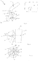
- a dental light curing device 10 is provided, of which only a light guide rod 12 as part of a handpiece in Fig. 1 is apparent.
- the light curing device in a conventional manner, a base station, at least one storage space.
- a light source is provided, which preferably has a plurality of LED chips.
- the LED chips direct the light to the light guide rod 12, and it is emitted according to the arrow 14 from a front end 16 of the light guide rod 12.
- Any reflected light corresponding to the arrows 18 is passed through the light guide rod 12 and passes to sensors which are arranged in the region of the LED chips. Because of the configuration in detail is out Fig. 3 directed.
- a control device 22 which can execute various control programs.
- the selection of the control programs is done partly automatically, but partly also via a dialing device, which can be realized, for example, as a button on the handpiece.
- pre-curing One of the control programs is referred to herein as "pre-curing" and is used according to the invention, as will be described in more detail here.
- FIG. 1 shown light curing device 10 directs light to a dental restoration 24, which is glued to a tooth stump 26.
- the dental restoration is pressed after applying the adhesive in a soft state, so that an adhesive excess 28 emerges laterally circumferentially out of the adhesive gap.
- Neighboring teeth 30 and 32 are disposed adjacent to the dental restoration 24 in the mesial and distal directions, respectively, so that the manner known per se, the interdental space 34 is quite limited.
- an adhesive gap 40 whose width is in Fig. 2 is exaggerated.
- the adhesive excess 28 is provided as a kind of bead laterally of the adhesive gap. According to the invention, it is acted upon by the end 16 of the light-conducting rod 12 of the light curing device 10 with radiation.
- Fig. 3 shows three LED chips with a first wavelength emission maximum, for example 470nm. Another LED chip 48 emits with an emission maximum of 410nm. This area and the area surrounding it represents the main wavelength range.
- an LED chip 50 is designed for a secondary wavelength range Fig. 3 provided in the embodiment according to Fig. 3 is centrally located. For example, green light can be detected in this.
- sensors 52, 54, 56 and 58 Surrounding the LED chips 42, 44, 46 are sensors 52, 54, 56 and 58 which sense the reflected radiation.
- the LED chip in the secondary wave area 50 is first switched on.
- the control device 22 detects when the end 16 according to Fig. 2 the dental restoration 24 and thus the adhesive excess 28 approaches. There, the emitted radiation is reflected according to the arrows 60 and fed to the sensors 52 to 58 via the Lichtleistab 12. If this is the case, according to the invention, the light source in a main wavelength range, ie via the chips 42, 44, 46 and 48 is turned on, for example for 2.2 seconds, so that the adhesive excess 28 is converted into a gel-like state.
- This procedure is carried out from four room corners - based on the dental restoration 24 - to ensure a uniform gelation of the adhesive excess 28.
- the light curing device 10 then turns off automatically, and it can now be manually removed the gel-like adhesive excess 28 easily.
- the type of radiation and also the duration of the exposure in the "pre-curing program" can be adapted to the requirements in a wide range. Also, while the light curing device is turned on in the main wavelength region, the sensors remain active, so that a control of the exposure made can be realized.
- the light source in the handpiece is then not designed as a light guide rod, but as a voltage supply and cooling bar.
- the associated sensor 30 is then arranged at the front end of the handpiece, in addition to the light source, preferably radially outside of this.
Landscapes
- Health & Medical Sciences (AREA)
- Oral & Maxillofacial Surgery (AREA)
- Dentistry (AREA)
- Epidemiology (AREA)
- Life Sciences & Earth Sciences (AREA)
- Animal Behavior & Ethology (AREA)
- General Health & Medical Sciences (AREA)
- Public Health (AREA)
- Veterinary Medicine (AREA)
- Engineering & Computer Science (AREA)
- Water Supply & Treatment (AREA)
- Dental Tools And Instruments Or Auxiliary Dental Instruments (AREA)
- Aviation & Aerospace Engineering (AREA)
- Mechanical Engineering (AREA)
Description
- Die Erfindung betrifft ein für zu härtendes Dentalmaterial vorgesehenes Dental-Lichthärtgerät, gemäß dem Oberbegriff von Anspruch 1, sowie ein System aus einem derartigen Dental-Lichthärtgerät und einer Klebekrone oder einer Klebebrücke.
- Dentale Kronen werden häufig auf Zahnstümpfen aufgeklebt, indem entweder der Zahnstumpf oder die Krone oder beide mit einen hiefür geeigneten Adhäsiv versehen und dann aufeinandergedrückt werden. Für die Haltbarkeit der Klebeverbindung ist es wesentlich, dass die Klebeflächen vollflächig mit dem Adhäsiv versehen sind. Hierzu ist seit langem bekannt, einen Überschuss an Adhäsiv bereitzustellen und dann die zu verklebenden Teile gegeneinander zu drücken, so dass der Überschuss teilweise seitlich herausquillt und jedenfalls eine vollflächige Abdeckung gewährleistet ist.
- Diese seit Jahrzehnten bekannte Maßnahme wird sowohl bei Zahnzement als auch bei anderen geeigneten Adhäsiven verwendet.
- Es ist stets dafür Sorge zu tragen, dass die Haftung sowohl auf der Oberfläche des betreffenden Zahnes als auch auf der gegenüberliegenden Oberfläche der Dentalrestauration die erforderliche Qualität aufweist. Typischerweise wird hierbei mindestens die Zahnoberfläche angeätzt, und es werden sogenannte Haftvermittler verwendet.
- Je nach dem Material der verwendeten Dentalrestauration werden unterschiedliche Adhäsive verwendet. Insbesondere bei Komposit besteht die Tendenz zu lichthärtenden Adhäsiven. Diese quellen dann typischerweise ringsum aus dem Klebespalt hinaus, wenn die Dentalrestauration mit der vorgegebenen Kraft angedrückt wird.
- Selbstverständlich muss dieser sogenannte Klebeüberschuss entfernt werden, wobei es gerade bei lichthärtenden Adhäsiven schwierig ist, den Klebeüberschuss zu entfernen, da er zum Verschmieren neigt.
- Es ist insofern bereits vorgeschlagen worden, den Klebeüberschuss anzuhärten, um ihn in einen gelartigen Zustand zu bringen und einfach abziehen zu können. Die Verwendung von üblichen Lichthärtgeräten hierzu ergab bei Versuchen, dass die Überschussentfernung jedoch Schwierigkeiten bereitet; wenn das Material zu stark ausgehärtet ist, lässt es sich nur sehr aufwändig abschleifen, beziehungsweise in den Zahnzwischenräumen praktisch gar nicht, und wenn es zu wenig ausgehärtet ist, verschmiert es lediglich, wenn versucht wird, das Material zu entfernen.
- Gerade die Belassung von Klebeüberschuss in mesial/distaler Richtung, also in den Zahnzwischenräumen, ist jedoch paradonthoseträchtig, da sich hier in engen und schlecht zugänglichen Innenecken leicht Ablagerungen und Bakterien sammeln können.
- Die
WO 2009/052016 schlägt vor, über ein einziges Bedienelement zwei verschiedene Betriebsmodi aufrufen zu können, was durch die Überwachung der Betätigung des einzigen Bedienelementes innerhalb einer festgelegten Zeitspanne erreicht werden soll. Einmalige Betätigung soll insofern einen ersten, zweimalige Betätigung einen anderen Betriebsmodus aktivieren. Diese Modi sollen bspw. unterschiedliche Lichtdosen, Bestrahlungsdauer oder verschiedene Wellenlängen umfassen können. - Die
EP 2 829 252 A1 beschreibt ebenfalls ein Lichthärtgerät, welches Lichtstrahlung mit unterschiedlicher Lichtleistung abgeben können soll. Die Abgabe von Strahlung mit einer reduzierten Leistung wird dort durch die Betätigung eines gesonderten Auslöseelements erreicht. - Daher liegt der Erfindung die Aufgabe zugrunde, ein für zu härtendes Dentalmaterial vorgesehenes Lichthärtgerät gemäß dem Oberbegriff von Anspruch 1 sowie ein hierzu passendes System gemäß dem Oberbegriff von Anspruch 10 zu schaffen, das die bekannten Probleme nicht aufweist, ohne dass ein zusätzliches Dentallichthärtgerät erforderlich wäre.
- Diese Aufgabe wird erfindungsgemäß durch Anspruch 1 gelöst. Vorteilhafte Weiterbildungen ergeben sich aus den Unteransprüchen.
- Erfindungsgemäß besonders günstig ist es, dass das erfindungsgemäße Steuerprogramm "Vorhärten" automatisch auslösbar ist. Dies wird erfindungsgemäß in besonderer Weise durch einen praktisch integriert realisierten und besonderen Näherungssensor sichergestellt. Wenn das Steuerprogramm einmal angewählt ist, erfasst das Lichthärtgerät bzw. dessen Steuervorrichtung die Annäherung an die Dentalrestauration mit dem Klebeüberschuss und löst das Vorhärtprogramm automatisch aus, wenn der Abstand ausreichend gering ist, um eine sichere Vorhärtung in der gewünschten Weise zu gewährleisten.
- Durch die feste Zeitwahl von beispielsweise zwei Sekunden ist sichergestellt, dass der Klebewulst weder zu lang noch zu kurz angehärtet wird, so dass er stets in dem erwünschten gelartigen Zustand vorliegt und auch aus den Zahnzwischenräumen sicher entfernbar ist. Es kommt nicht zum Verschmieren, und das Erfordernis des Abschleifens entfällt vollständig.
- Es wird erfindungsgemäß auch verhindert, dass Steuerprogramm "Vorhärten" vorzeitig ausgelöst wird. So lässt sich erfindungsgemäß erfassen, wenn die Lichtaustrittsfläche des Lichtleitstabs des Lichthärtgeräts in ausreichend geringem Abstand von der Zahnoberfläche ist. Hierzu werden die Unterschiede der Reflexionseigenschaften zwischen beispielsweise der Mundschleimhaut und der Dentalrestauration bzw. des Zahn ausgenutzt. Das
- Lichthärtgerät emittiert zunächst Licht in einem Nebenwellenlängenbereich, beispielsweise grünes Licht. Dieses ist in einem Wellenlängenbereich, der deutlich verschieden ist, von dem Wellenbereich des Empfindlichkeitsmaximums des zu polymerisierenden Adhäsivs.
- In dem Handstück des Lichthärtgeräts ist ein Sensor der Lichtquelle benachbart vorgesehen, der durch den Lichtleitstab zurückgeleitetes Licht erfasst. Wenn nun die Lichtaustrittsfläche des Lichtleitstabs sich dem Klebeüberschuss annähert, wird das Licht im Nebenwellenlängenbereich mit einer bestimmten Intensität reflektiert. Das reflektierte Licht wird vom Sensor erfasst und ein entsprechendes Steuersignal der Steuervorrichtung für die Auslösung des Steuerprogramms "Vorhärten" bereitgestellt.
- Es versteht sich, dass das Polymerisationslicht dann im Hauptwellenlängenbereich emittiert wird und die Lichtquelle für die vorgegebene Vorhärtzeit, beispielsweise 1 bis 3 Sekunden, eingeschaltet wird.
- Für die bessere Unterscheidung des Reflexionslicht von Umgebungslicht ist es bevorzugt, das Licht im Nebenwellenlängenbereich gepulst oder in Sinusform abzugeben. Die Erfassung in dem Sensor erfolgt dann über die Größe der erfassten Amplitude des reflektierten Lichts, so dass Umgebungslicht automatisch ausgeblendet wird.
- Erfindungsgemäß ist es günstig, wenn das Steuerprogramm "Vorhärten" an allen vier Seiten beispielsweise der Krone ausgelöst wird, also beispielsweise zunächst von der distal/vestibulären Seite, dann von der distal/lingualen Seite, dann von der mesio/lingualen Seite und anschließen von der mesio/vestibulären Seite.
- Die exakte Dosierung erlaubt es, den Klebeüberschuss in einem Wulst abzuziehen, was eine erhebliche Arbeitserleichterung gegenüber der bislang verwendeten problematischen Technik darstellt.
- Weitere Vorteile, Einzelheiten und Merkmale ergeben sich aus der nachfolgenden Beschreibung eines Ausführungsbeispiels der Erfindung anhand der Zeichnungen:
Es zeigen: - Fig. 1
- eine schematische Ansicht eines erfindungsgemäßen Systems aus einem Lichthärtgerät und einer Dentalrestauration mit Klebeüberschuss;
- Fig. 2
- eine vergrößerte Darstellung eines Details aus
Fig. 1 , nämlich des Klebstoffüberschusses und des vorderen Ende des Lichtleitstabs des Lichthärtgeräts und; - Fig. 3
- eine schematische Ansicht der Verteilung von LED-Lichtquellen und Sensoren am rückwärtigen Ende des Lichtleitstabs.
- In der Ausführungsform gemäß
Fig. 1 ist ein Dental-Lichthärtgerät 10 vorgesehen, von dem lediglich ein Lichtleitstab 12 als Teil eines Handstücks inFig. 1 ersichtlich ist. Zusätzlich weist das Lichthärtgerät in an sich bekannter Weise eine Basisstation auf, mindestens einen Lagerplatz. - Am gehäusenahen Ende des Lichtleitstabs 12 ist eine Lichtquelle vorgesehen, die bevorzugt mehrere LED-Chips aufweist. Die LED-Chips leiten das Licht dem Lichtleitstab 12 zu, und es wird entsprechend dem Pfeil 14 aus einem vorderen Ende 16 des Lichtleitstabs 12 emittiert.
- Etwaiges reflektiertes Licht entsprechend den Pfeilen 18 wird durch den Lichtleitstab 12 hindurchgeleitet und gelangt zu Sensoren, die im Bereich der LED-Chips angeordnet sind. Wegen der Ausgestaltung im Einzelnen sei aus
Fig. 3 verwiesen. - Auch wenn hier die Erfindung unter Bezug auf einen Lichtleitstab beschrieben ist, versteht es sich, dass an Stelle dessen beliebige andere Lichtleitvorrichtungen, beispielsweise auch flexible Lichtleiter, realisierbar sind, ohne den Bereich der Erfindung zu verlassen.
- Im schematisch dargestellten Handstück 20 ist eine Steuervorrichtung 22 vorgesehen, die verschiedene Steuerprogramme ausführen kann. Die Auswahl der Steuerprogramme erfolgt teils automatisch, teils aber auch über eine Wählvorrichtung, die beispielsweise als Taster an dem Handstück realisiert sein kann.
- Eines der Steuerprogramme ist hier als "Vorhärten" bezeichnet und wird erfindungsgemäß eingesetzt, wie es hier näher beschrieben wird.
- Das in
Fig. 1 dargestellte Lichthärtgerät 10 leitet Licht einer Dentalrestauration 24 zu, die auf einem Zahnstumpf 26 aufgeklebt ist. Die Dentalrestauration ist nach Applizieren des Adhäsivs in weichem Zustand aufgedrückt, so dass ein Klebeüberschuss 28 seitlich umlaufend aus dem Klebespalt heraustritt. - Dies ist in vergrößerter Darstellung aus
Fig. 2 ersichtlich. - Der Dentalrestauration 24 benachbart in mesial bzw. distaler Richtung sind Nachbarzähne 30 und 32 angeordnet, so dass die an sich bekannter Weise der Zahnzwischenraum 34 recht begrenzt ist.
- Zwischen der Dentalrestauration 24 und dem Zahnstumpf 26 besteht gemäß
Fig. 2 ein Klebespalt 40, dessen Breite inFig. 2 übertrieben dargestellt ist. Der Klebeüberschuss 28 ist als eine Art Wulst seitlich des Klebespalts vorgesehen. Erfindungsgemäß wird er mit dem Ende 16 des Lichtleitstabs 12 des Lichthärtgeräts 10 mit Strahlung beaufschlagt. - Für die Erläuterung des Ablaufs wird auch auf
Fig. 3 Bezug genommen. -
Fig. 3 zeigt drei LED-Chips mit einem ersten Wellenlängenemissionsmaximum, beispielsweise 470nm. Ein weiterer LED-Chip 48 emittiert mit einem Emissionsmaximum von 410nm. Dieser Bereich und der diesen umgebende Bereich stellt den Hauptwellenlängenbereich dar. Zusätzlich ist erfindungsgemäß ein LED-Chip 50 für einen Nebenwellenlängenbereich ausFig. 3 vorgesehen, das in der Ausführungsform gemäßFig. 3 zentral angeordnet ist. Beispielsweise kann grünes Licht in diesem ermittelt werden. - Die LED-Chips 42, 44, 46 umgebend sind Sensoren 52, 54, 56 und 58 vorgesehen, die die reflektierte Strahlung erfassen.
- Im Betrieb wird nun zunächst der LED-Chip im Nebenwellenbereich 50 eingeschaltet. Die Steuervorrichtung 22 erfasst, wenn sich das Ende 16 gemäß
Fig. 2 der Dentalrestauration 24 und damit dem Klebeüberschuss 28 annähert. Dort wird gemäß den Pfeilen 60 die emittierte Strahlung reflektiert und über den Lichtleistab 12 den Sensoren 52 bis 58 zugeleitet. Wenn dies der Fall ist, wird erfindungsgemäß die Lichtquelle in einem Hauptwellenlängenbereich, also über die Chips 42, 44, 46 und 48 eingeschaltet, und zwar beispielsweise für 2,2 Sekunden, so dass der Klebeüberschuss 28 in einen gelartigen Zustand überführt wird. - Dieses Prozedere wird von vier Raumecken aus - bezogen auf die Dentalrestauration 24 - durchgeführt, um eine gleichmäßige Gelierung des Klebeüberschusses 28 zu gewährleisten.
- Hieran anschließend schaltet sich das Lichthärtgerät 10 dann automatisch ab, und es kann nun manuell der gelartige Klebeüberschuss 28 leicht entfernt werden.
- Es versteht sich, dass die Art der Strahlung und auch die Dauer der Belichtung im "Vorhärtprogramm" in weiten Bereichen an die Erfordernisse anpassbar ist. Auch können während des Einschaltens des Lichthärtgeräts im Hauptwellenlängenbereich die Sensoren aktivgeschaltet verbleiben, so dass eine Kontrolle der vorgenommenen Belichtung realisierbar ist.
- In einer weiteren Ausführungsform ist es vorgesehen, die Lichtquelle in dem Handstück an das vordere Ende eines Stabes zu verlagern, der dann nicht als Lichtleitstab, sondern als Spannungsversorgungs- und Kühlstab ausgebildet ist. Auch der zugehörige Sensor 30 ist dann an dem vorderen Ende des Handstücks angeordnet, und zwar neben der Lichtquelle, bevorzugt radial außerhalb dieser.
Claims (10)
- Für zu härtendes Dentalmaterial vorgesehenes Dental-Lichthärtgerät (10), das ein Handstück (20) und eine Basisstation aufweist, wobei das Handstück (20) eine Lichtquelle, insbesondere mit mehreren LED-Chips (42, 44, 46 und 48); die - bezogen auf die optische Achse - nebeneinander angeordnet sind, eine Steuervorrichtung (22) für die Lichtquelle und mindestens einen Sensor aufweist, der der Lichtquelle benachbart angeordnet ist, wobei sich - wiederum bezogen auf die optische Achse - vor der Lichtquelle eine Lichtleitvorrichtung, insbesondere ein Lichtleitstab (12), erstreckt, der einen Durchlassbereich für Wellenlängen aufweist, der mindestens blaues sichtbares Licht umfasst und insbesondere auch grünes sichtbares Licht und UV-Licht, und mit einer Wählvorrichtung für Steuerprogramme der Steuervorrichtung (22), insbesondere einem Taster an dem Handstück (20), wobei die Steuervorrichtung (22) auch ein Steuerprogramm "Vorhärten" aufweist, das mit der Wählvorrichtung anwählbar ist und in welchem das Lichthärtgerät mit einem Nebenwellenlängenbereich einschaltbar ist, der von einem Hauptwellenlängenbereich der Lichthärtung verschieden ist und dessen Lichtstrahlung außerhalb des Empfindlichkeitsbereichs des zu härtenden Dentalmaterials ist, dadurch gekennzeichnet, dass die Steuervorrichtung (22) die Lichtquelle im Hauptwellenlängenbereich automatisch zur Vorhärtung von Klebeüberschuss (28) bei Dentalrestaurationen, insbesondere bei Klebekronen oder Klebebrücken automatisch einschaltet, wenn mindestens ein Sensor das von einer Zahnoberfläche reflektierte Licht im Nebenwellenlängenbereich erfasst.
- Dental-Lichthärtgerät nach Anspruch 1, dadurch gekennzeichnet, dass die Einschaltzeit der Lichtquelle im Nebenwellenlängenbereich für das Vorhärten für die Klebstoffüberschussentfernung der aufgeklebten Krone weniger als 3 Sekunden beträgt, insbesondere 1 bis 2 Sekunden, und automatisch endet.
- Dental-Lichthärtgerät nach Anspruch 1 oder 2, dadurch gekennzeichnet, dass die Lichtquelle für die Zahndetektion gepulstes Licht im Nebenwellenlängenbereich abgibt.
- Dental-Lichthärtgerät nach einem der vorhergehenden Ansprüche, dadurch gekennzeichnet, dass der Nebenwellenlängenbereich im Bereicht grünen Lichts liegt, insbesondere in einem schmalbandigen Bereich mit einem Wellenlängenspektrum von etwa 10 nm im grünen Lichtspektrum.
- Dental-Lichthärtgerät nach einem der vorhergehenden Ansprüche, dadurch gekennzeichnet, dass der Sensor einen spektralen Empfindlichkeitsbereich aufweist, der den Bereich zwischen 400 nm und 570 nm abdeckt und ein Empfindlichkeitsmaximum insbesondere zwischen 460 nm und 480 nm aufweist.
- Dental-Lichthärtgerät nach einem der vorhergehenden Ansprüche, dadurch gekennzeichnet, dass die Steuervorrichtung (22) die Lichtquelle im Hauptwellenlängenbereich dann einschaltet, wenn die von dem Sensor gemessenen Amplituden des reflektierten Lichts einen Schwellenwert übersteigen, der durch das Verhältnis zwischen Impuls und Pause der Einschaltung der Lichtquelle mit dem Nebenwellenlängenbereich vorgegeben ist.
- Dental-Lichthärtgerät nach einem der vorhergehenden Ansprüche, dadurch gekennzeichnet, dass die Lichtleitvorrichtung einen Lichtleitstab (12) aufweist, der austauschbar ist und ein Abkröpfende aufweist, und dass der Lichtleitstab (12), insbesondere zum Vorhärten von Klebstoffüberschüssen im distalen Bereich von Molaren durch einen Lichtleitstab (12) mit einem Abkröpfwinkel austauschbar ist, der deutlich mehr als 45 ° beträgt, insbesondere zwischen 60° und 80°.
- Dental-Lichthärtgerät nach einem der vorhergehenden Ansprüche, dadurch gekennzeichnet, dass die Lichtquelle mehrere LED-Chips (42, 44, 46 und 48) aufweist, die symmetrisch zueinander auf einer Ebene angebracht sind und auf einer gemeinsamen Printplatte montiert sind, wobei ein LED-Chip (50) im Nebenwellenlängenbereich und die übrigen insbesondere zwei bis zehn LED-Chips (42, 44, 46 und 48) im Hauptwellenlängenbereich emittieren.
- Dental-Lichthärtgerät nach einem der vorhergehenden Ansprüche, dadurch gekennzeichnet, dass der mindestens eine Sensor unmittelbar angrenzend an einen Reflektor eines LED-Chips (42, 44, 46 und 48) der Lichtquelle angeordnet ist, insbesondere angrenzend an zwei Reflektoren zweier benachbarter LED-Chips (42, 44, 46 und 48).
- System aus einem Dental-Lichthärtgerät (10) und einer Klebekrone oder einer Klebebrücke, mit den Merkmalen von Anspruch 1.
Priority Applications (7)
| Application Number | Priority Date | Filing Date | Title |
|---|---|---|---|
| EP15172598.3A EP3106123B1 (de) | 2015-06-17 | 2015-06-17 | Dental-lichthärtgerät |
| ES15172598T ES2704242T3 (es) | 2015-06-17 | 2015-06-17 | Dispositivo de fotocurado dental |
| US15/735,469 US10376350B2 (en) | 2015-06-17 | 2016-06-17 | Dental light curing device |
| JP2017565231A JP6592536B2 (ja) | 2015-06-17 | 2016-06-17 | 歯科用光硬化装置 |
| PCT/EP2016/064029 WO2016202992A1 (de) | 2015-06-17 | 2016-06-17 | Dental-lichthärtgerät |
| CN201680034920.2A CN107750149B (zh) | 2015-06-17 | 2016-06-17 | 牙科光固化机 |
| CA2987345A CA2987345A1 (en) | 2015-06-17 | 2016-06-17 | Dental light-curing device |
Applications Claiming Priority (1)
| Application Number | Priority Date | Filing Date | Title |
|---|---|---|---|
| EP15172598.3A EP3106123B1 (de) | 2015-06-17 | 2015-06-17 | Dental-lichthärtgerät |
Publications (2)
| Publication Number | Publication Date |
|---|---|
| EP3106123A1 EP3106123A1 (de) | 2016-12-21 |
| EP3106123B1 true EP3106123B1 (de) | 2018-10-03 |
Family
ID=53404458
Family Applications (1)
| Application Number | Title | Priority Date | Filing Date |
|---|---|---|---|
| EP15172598.3A Active EP3106123B1 (de) | 2015-06-17 | 2015-06-17 | Dental-lichthärtgerät |
Country Status (7)
| Country | Link |
|---|---|
| US (1) | US10376350B2 (de) |
| EP (1) | EP3106123B1 (de) |
| JP (1) | JP6592536B2 (de) |
| CN (1) | CN107750149B (de) |
| CA (1) | CA2987345A1 (de) |
| ES (1) | ES2704242T3 (de) |
| WO (1) | WO2016202992A1 (de) |
Families Citing this family (3)
| Publication number | Priority date | Publication date | Assignee | Title |
|---|---|---|---|---|
| WO2016044549A1 (en) | 2014-09-17 | 2016-03-24 | Garrison Dental Solutions, Llc | Dental curing light |
| US10871326B2 (en) * | 2018-09-06 | 2020-12-22 | Stolle Machinery Company, Llc | Infrared can curing oven |
| EP3991686A1 (de) * | 2020-11-02 | 2022-05-04 | Ivoclar Vivadent AG | Verfahren zum befestigen eines restaurationsteils |
Family Cites Families (13)
| Publication number | Priority date | Publication date | Assignee | Title |
|---|---|---|---|---|
| DE9204621U1 (de) * | 1992-04-03 | 1992-07-30 | Oralia Dentalprodukte Gmbh, 7750 Konstanz, De | |
| DE10107099C2 (de) * | 2001-02-14 | 2003-12-11 | Sirona Dental Systems Gmbh | Einrichtung zur Polymerisation von lichthärtenden Kunststoffen, insbesondere von zahnärztlichen Füll- oder Klebematerialien |
| US6835064B2 (en) * | 2001-11-09 | 2004-12-28 | Ivoclar Vivadent Ag | Light hardening device and method for hardening a polymerizable mass for dental applications |
| AU2003222430A1 (en) * | 2002-05-02 | 2003-11-17 | Cadent Ltd. | Appliance for positioning orthodontic components |
| JP2004275276A (ja) * | 2003-03-13 | 2004-10-07 | Gc Corp | ファイバーロッド及び光照射装置 |
| FR2909276A1 (fr) * | 2006-12-04 | 2008-06-06 | Satelec Sa | Dispositif de photopolymerisation automatique |
| GB0720165D0 (en) * | 2007-10-16 | 2007-11-28 | 3M Innovative Properties Co | Light-emitting device |
| DE102008031094A1 (de) * | 2008-07-01 | 2010-01-07 | Ivoclar Vivadent Ag | Gerät zum Lichthärten eines Dentalobjekts |
| DE102013208838B4 (de) * | 2013-05-14 | 2015-03-05 | Schott Ag | Beleuchtungseinrichtung mit erweitertem Nutzspektrum und deren Verwendung |
| CN203354682U (zh) * | 2013-07-09 | 2013-12-25 | 丹美科技有限公司 | 用于检测牙齿疾病与固化树脂的医疗装置 |
| US11490999B2 (en) * | 2013-07-23 | 2022-11-08 | Ivoclar Vivadent Ag | Light curing device for dental restoration materials and method of curing dental restoration materials |
| EP3308740B1 (de) * | 2013-07-23 | 2023-06-21 | Ivoclar Vivadent AG | Lichthärtgerät für dentalrestaurationsmaterialien |
| US20160113746A1 (en) * | 2014-10-28 | 2016-04-28 | Joseph F. Bringley | Light source, detector and luminescent composite |
-
2015
- 2015-06-17 EP EP15172598.3A patent/EP3106123B1/de active Active
- 2015-06-17 ES ES15172598T patent/ES2704242T3/es active Active
-
2016
- 2016-06-17 CA CA2987345A patent/CA2987345A1/en not_active Abandoned
- 2016-06-17 WO PCT/EP2016/064029 patent/WO2016202992A1/de active Application Filing
- 2016-06-17 JP JP2017565231A patent/JP6592536B2/ja active Active
- 2016-06-17 US US15/735,469 patent/US10376350B2/en active Active
- 2016-06-17 CN CN201680034920.2A patent/CN107750149B/zh active Active
Non-Patent Citations (1)
| Title |
|---|
| None * |
Also Published As
| Publication number | Publication date |
|---|---|
| US20180153668A1 (en) | 2018-06-07 |
| CN107750149B (zh) | 2020-07-03 |
| ES2704242T3 (es) | 2019-03-15 |
| CA2987345A1 (en) | 2016-12-22 |
| US10376350B2 (en) | 2019-08-13 |
| WO2016202992A1 (de) | 2016-12-22 |
| CN107750149A (zh) | 2018-03-02 |
| JP6592536B2 (ja) | 2019-10-16 |
| EP3106123A1 (de) | 2016-12-21 |
| JP2018517524A (ja) | 2018-07-05 |
Similar Documents
| Publication | Publication Date | Title |
|---|---|---|
| DE3910438C2 (de) | ||
| EP3106123B1 (de) | Dental-lichthärtgerät | |
| EP1884217B1 (de) | Handgeführtes Lichthärtgerät | |
| DE10121348A1 (de) | Optische Vorrichtung und Harzhärtungsvorrichtung | |
| WO2014044711A1 (de) | Vorrichtung und verfahren zur applikation von lichtkompositen | |
| WO2002080803A1 (de) | Baueteil eines laserbehandlungsgeräts sowie laserbehandlungsgerät mit beleuchtungssystem | |
| DE10107099C2 (de) | Einrichtung zur Polymerisation von lichthärtenden Kunststoffen, insbesondere von zahnärztlichen Füll- oder Klebematerialien | |
| EP2829252B1 (de) | Lichthärtgerät für Dentalrestaurationsmaterialien | |
| EP3330683B1 (de) | Lichthärtgerät | |
| DE102004019616A1 (de) | Linse zum Aufstrahlen von Härtungslicht auf einen Dentalkleber sowie Systeme und Verfahren zur Verwendung derartiger Linsen | |
| EP0201107B1 (de) | Vorrichtung zum Aushärten von lichthärtendem Fingernagel- und Fussnagelersatz | |
| EP3357452B1 (de) | Lichthärtgerät | |
| EP3394503B1 (de) | Scheinwerfer für fahrzeuge mit zumindest einem laser-lichtmodul | |
| DE202007014172U1 (de) | Modelliervorrichtung für einen strahlungshärtenden Werkstoff | |
| DE202014101021U1 (de) | Therapievorrichtung | |
| EP1260195B1 (de) | Vorsatzelement für Lichtleiter | |
| EP3991687A1 (de) | System aus einem laser und einem adhäsiv zum befestigen eines dentalrestaurationsteils | |
| DE10049778C1 (de) | Dermatologisches Handstück | |
| EP0847254B1 (de) | Zahnärztliches instrument | |
| EP2134285A1 (de) | Zahnärztliches laser-behandlungsinstrument mit licht-auskoppelelement | |
| DE102009049107B4 (de) | Vorrichtung und Verfahren zur Bekantung von Werkstücken | |
| DE102007008116A1 (de) | Zahnärztliche Laser-Behandlungsvorrichtung mit Pilotstrahlung |
Legal Events
| Date | Code | Title | Description |
|---|---|---|---|
| PUAI | Public reference made under article 153(3) epc to a published international application that has entered the european phase |
Free format text: ORIGINAL CODE: 0009012 |
|
| STAA | Information on the status of an ep patent application or granted ep patent |
Free format text: STATUS: THE APPLICATION HAS BEEN PUBLISHED |
|
| AK | Designated contracting states |
Kind code of ref document: A1 Designated state(s): AL AT BE BG CH CY CZ DE DK EE ES FI FR GB GR HR HU IE IS IT LI LT LU LV MC MK MT NL NO PL PT RO RS SE SI SK SM TR |
|
| AX | Request for extension of the european patent |
Extension state: BA ME |
|
| STAA | Information on the status of an ep patent application or granted ep patent |
Free format text: STATUS: REQUEST FOR EXAMINATION WAS MADE |
|
| 17P | Request for examination filed |
Effective date: 20170419 |
|
| RBV | Designated contracting states (corrected) |
Designated state(s): AL AT BE BG CH CY CZ DE DK EE ES FI FR GB GR HR HU IE IS IT LI LT LU LV MC MK MT NL NO PL PT RO RS SE SI SK SM TR |
|
| RIC1 | Information provided on ipc code assigned before grant |
Ipc: B64D 9/00 20060101ALI20180305BHEP Ipc: B64C 1/22 20060101ALI20180305BHEP Ipc: A61C 13/15 20060101AFI20180305BHEP Ipc: B64C 1/20 20060101ALI20180305BHEP |
|
| GRAP | Despatch of communication of intention to grant a patent |
Free format text: ORIGINAL CODE: EPIDOSNIGR1 |
|
| STAA | Information on the status of an ep patent application or granted ep patent |
Free format text: STATUS: GRANT OF PATENT IS INTENDED |
|
| RIC1 | Information provided on ipc code assigned before grant |
Ipc: A61C 13/15 20060101AFI20180326BHEP |
|
| INTG | Intention to grant announced |
Effective date: 20180425 |
|
| GRAS | Grant fee paid |
Free format text: ORIGINAL CODE: EPIDOSNIGR3 |
|
| GRAA | (expected) grant |
Free format text: ORIGINAL CODE: 0009210 |
|
| STAA | Information on the status of an ep patent application or granted ep patent |
Free format text: STATUS: THE PATENT HAS BEEN GRANTED |
|
| AK | Designated contracting states |
Kind code of ref document: B1 Designated state(s): AL AT BE BG CH CY CZ DE DK EE ES FI FR GB GR HR HU IE IS IT LI LT LU LV MC MK MT NL NO PL PT RO RS SE SI SK SM TR |
|
| REG | Reference to a national code |
Ref country code: GB Ref legal event code: FG4D Free format text: NOT ENGLISH |
|
| REG | Reference to a national code |
Ref country code: CH Ref legal event code: EP Ref country code: AT Ref legal event code: REF Ref document number: 1047818 Country of ref document: AT Kind code of ref document: T Effective date: 20181015 |
|
| REG | Reference to a national code |
Ref country code: IE Ref legal event code: FG4D Free format text: LANGUAGE OF EP DOCUMENT: GERMAN Ref country code: DE Ref legal event code: R096 Ref document number: 502015006201 Country of ref document: DE |
|
| REG | Reference to a national code |
Ref country code: CH Ref legal event code: NV Representative=s name: KELLER AND PARTNER PATENTANWAELTE AG, CH |
|
| REG | Reference to a national code |
Ref country code: SE Ref legal event code: TRGR |
|
| REG | Reference to a national code |
Ref country code: NL Ref legal event code: MP Effective date: 20181003 |
|
| REG | Reference to a national code |
Ref country code: LT Ref legal event code: MG4D |
|
| REG | Reference to a national code |
Ref country code: ES Ref legal event code: FG2A Ref document number: 2704242 Country of ref document: ES Kind code of ref document: T3 Effective date: 20190315 |
|
| PG25 | Lapsed in a contracting state [announced via postgrant information from national office to epo] |
Ref country code: NL Free format text: LAPSE BECAUSE OF FAILURE TO SUBMIT A TRANSLATION OF THE DESCRIPTION OR TO PAY THE FEE WITHIN THE PRESCRIBED TIME-LIMIT Effective date: 20181003 |
|
| PG25 | Lapsed in a contracting state [announced via postgrant information from national office to epo] |
Ref country code: HR Free format text: LAPSE BECAUSE OF FAILURE TO SUBMIT A TRANSLATION OF THE DESCRIPTION OR TO PAY THE FEE WITHIN THE PRESCRIBED TIME-LIMIT Effective date: 20181003 Ref country code: LV Free format text: LAPSE BECAUSE OF FAILURE TO SUBMIT A TRANSLATION OF THE DESCRIPTION OR TO PAY THE FEE WITHIN THE PRESCRIBED TIME-LIMIT Effective date: 20181003 Ref country code: NO Free format text: LAPSE BECAUSE OF FAILURE TO SUBMIT A TRANSLATION OF THE DESCRIPTION OR TO PAY THE FEE WITHIN THE PRESCRIBED TIME-LIMIT Effective date: 20190103 Ref country code: FI Free format text: LAPSE BECAUSE OF FAILURE TO SUBMIT A TRANSLATION OF THE DESCRIPTION OR TO PAY THE FEE WITHIN THE PRESCRIBED TIME-LIMIT Effective date: 20181003 Ref country code: CZ Free format text: LAPSE BECAUSE OF FAILURE TO SUBMIT A TRANSLATION OF THE DESCRIPTION OR TO PAY THE FEE WITHIN THE PRESCRIBED TIME-LIMIT Effective date: 20181003 Ref country code: IS Free format text: LAPSE BECAUSE OF FAILURE TO SUBMIT A TRANSLATION OF THE DESCRIPTION OR TO PAY THE FEE WITHIN THE PRESCRIBED TIME-LIMIT Effective date: 20190203 Ref country code: BG Free format text: LAPSE BECAUSE OF FAILURE TO SUBMIT A TRANSLATION OF THE DESCRIPTION OR TO PAY THE FEE WITHIN THE PRESCRIBED TIME-LIMIT Effective date: 20190103 Ref country code: PL Free format text: LAPSE BECAUSE OF FAILURE TO SUBMIT A TRANSLATION OF THE DESCRIPTION OR TO PAY THE FEE WITHIN THE PRESCRIBED TIME-LIMIT Effective date: 20181003 Ref country code: LT Free format text: LAPSE BECAUSE OF FAILURE TO SUBMIT A TRANSLATION OF THE DESCRIPTION OR TO PAY THE FEE WITHIN THE PRESCRIBED TIME-LIMIT Effective date: 20181003 |
|
| PG25 | Lapsed in a contracting state [announced via postgrant information from national office to epo] |
Ref country code: GR Free format text: LAPSE BECAUSE OF FAILURE TO SUBMIT A TRANSLATION OF THE DESCRIPTION OR TO PAY THE FEE WITHIN THE PRESCRIBED TIME-LIMIT Effective date: 20190104 Ref country code: AL Free format text: LAPSE BECAUSE OF FAILURE TO SUBMIT A TRANSLATION OF THE DESCRIPTION OR TO PAY THE FEE WITHIN THE PRESCRIBED TIME-LIMIT Effective date: 20181003 Ref country code: PT Free format text: LAPSE BECAUSE OF FAILURE TO SUBMIT A TRANSLATION OF THE DESCRIPTION OR TO PAY THE FEE WITHIN THE PRESCRIBED TIME-LIMIT Effective date: 20190203 Ref country code: RS Free format text: LAPSE BECAUSE OF FAILURE TO SUBMIT A TRANSLATION OF THE DESCRIPTION OR TO PAY THE FEE WITHIN THE PRESCRIBED TIME-LIMIT Effective date: 20181003 |
|
| REG | Reference to a national code |
Ref country code: DE Ref legal event code: R097 Ref document number: 502015006201 Country of ref document: DE |
|
| PG25 | Lapsed in a contracting state [announced via postgrant information from national office to epo] |
Ref country code: DK Free format text: LAPSE BECAUSE OF FAILURE TO SUBMIT A TRANSLATION OF THE DESCRIPTION OR TO PAY THE FEE WITHIN THE PRESCRIBED TIME-LIMIT Effective date: 20181003 |
|
| PLBE | No opposition filed within time limit |
Free format text: ORIGINAL CODE: 0009261 |
|
| STAA | Information on the status of an ep patent application or granted ep patent |
Free format text: STATUS: NO OPPOSITION FILED WITHIN TIME LIMIT |
|
| PG25 | Lapsed in a contracting state [announced via postgrant information from national office to epo] |
Ref country code: RO Free format text: LAPSE BECAUSE OF FAILURE TO SUBMIT A TRANSLATION OF THE DESCRIPTION OR TO PAY THE FEE WITHIN THE PRESCRIBED TIME-LIMIT Effective date: 20181003 Ref country code: SK Free format text: LAPSE BECAUSE OF FAILURE TO SUBMIT A TRANSLATION OF THE DESCRIPTION OR TO PAY THE FEE WITHIN THE PRESCRIBED TIME-LIMIT Effective date: 20181003 Ref country code: SM Free format text: LAPSE BECAUSE OF FAILURE TO SUBMIT A TRANSLATION OF THE DESCRIPTION OR TO PAY THE FEE WITHIN THE PRESCRIBED TIME-LIMIT Effective date: 20181003 Ref country code: EE Free format text: LAPSE BECAUSE OF FAILURE TO SUBMIT A TRANSLATION OF THE DESCRIPTION OR TO PAY THE FEE WITHIN THE PRESCRIBED TIME-LIMIT Effective date: 20181003 |
|
| 26N | No opposition filed |
Effective date: 20190704 |
|
| PG25 | Lapsed in a contracting state [announced via postgrant information from national office to epo] |
Ref country code: SI Free format text: LAPSE BECAUSE OF FAILURE TO SUBMIT A TRANSLATION OF THE DESCRIPTION OR TO PAY THE FEE WITHIN THE PRESCRIBED TIME-LIMIT Effective date: 20181003 |
|
| PG25 | Lapsed in a contracting state [announced via postgrant information from national office to epo] |
Ref country code: MC Free format text: LAPSE BECAUSE OF FAILURE TO SUBMIT A TRANSLATION OF THE DESCRIPTION OR TO PAY THE FEE WITHIN THE PRESCRIBED TIME-LIMIT Effective date: 20181003 |
|
| REG | Reference to a national code |
Ref country code: BE Ref legal event code: MM Effective date: 20190630 |
|
| PG25 | Lapsed in a contracting state [announced via postgrant information from national office to epo] |
Ref country code: TR Free format text: LAPSE BECAUSE OF FAILURE TO SUBMIT A TRANSLATION OF THE DESCRIPTION OR TO PAY THE FEE WITHIN THE PRESCRIBED TIME-LIMIT Effective date: 20181003 |
|
| PG25 | Lapsed in a contracting state [announced via postgrant information from national office to epo] |
Ref country code: IE Free format text: LAPSE BECAUSE OF NON-PAYMENT OF DUE FEES Effective date: 20190617 |
|
| PG25 | Lapsed in a contracting state [announced via postgrant information from national office to epo] |
Ref country code: LU Free format text: LAPSE BECAUSE OF NON-PAYMENT OF DUE FEES Effective date: 20190617 Ref country code: BE Free format text: LAPSE BECAUSE OF NON-PAYMENT OF DUE FEES Effective date: 20190630 |
|
| REG | Reference to a national code |
Ref country code: CH Ref legal event code: PFA Owner name: IVOCLAR VIVADENT AG, LI Free format text: FORMER OWNER: IVOCLAR VIVADENT AG, LI |
|
| PG25 | Lapsed in a contracting state [announced via postgrant information from national office to epo] |
Ref country code: CY Free format text: LAPSE BECAUSE OF FAILURE TO SUBMIT A TRANSLATION OF THE DESCRIPTION OR TO PAY THE FEE WITHIN THE PRESCRIBED TIME-LIMIT Effective date: 20181003 |
|
| PG25 | Lapsed in a contracting state [announced via postgrant information from national office to epo] |
Ref country code: HU Free format text: LAPSE BECAUSE OF FAILURE TO SUBMIT A TRANSLATION OF THE DESCRIPTION OR TO PAY THE FEE WITHIN THE PRESCRIBED TIME-LIMIT; INVALID AB INITIO Effective date: 20150617 Ref country code: MT Free format text: LAPSE BECAUSE OF FAILURE TO SUBMIT A TRANSLATION OF THE DESCRIPTION OR TO PAY THE FEE WITHIN THE PRESCRIBED TIME-LIMIT Effective date: 20181003 |
|
| PG25 | Lapsed in a contracting state [announced via postgrant information from national office to epo] |
Ref country code: MK Free format text: LAPSE BECAUSE OF FAILURE TO SUBMIT A TRANSLATION OF THE DESCRIPTION OR TO PAY THE FEE WITHIN THE PRESCRIBED TIME-LIMIT Effective date: 20181003 |
|
| P01 | Opt-out of the competence of the unified patent court (upc) registered |
Effective date: 20230607 |
|
| PGFP | Annual fee paid to national office [announced via postgrant information from national office to epo] |
Ref country code: IT Payment date: 20230426 Year of fee payment: 9 Ref country code: FR Payment date: 20230508 Year of fee payment: 9 Ref country code: DE Payment date: 20230522 Year of fee payment: 9 |
|
| PGFP | Annual fee paid to national office [announced via postgrant information from national office to epo] |
Ref country code: SE Payment date: 20230509 Year of fee payment: 9 Ref country code: AT Payment date: 20230509 Year of fee payment: 9 |
|
| PGFP | Annual fee paid to national office [announced via postgrant information from national office to epo] |
Ref country code: GB Payment date: 20230508 Year of fee payment: 9 Ref country code: ES Payment date: 20230704 Year of fee payment: 9 Ref country code: CH Payment date: 20230702 Year of fee payment: 9 |