EP3104150A1 - Sheet for pressure sensor, pressure sensor, and method for producing sheet for pressure sensor - Google Patents
Sheet for pressure sensor, pressure sensor, and method for producing sheet for pressure sensor Download PDFInfo
- Publication number
- EP3104150A1 EP3104150A1 EP15746322.5A EP15746322A EP3104150A1 EP 3104150 A1 EP3104150 A1 EP 3104150A1 EP 15746322 A EP15746322 A EP 15746322A EP 3104150 A1 EP3104150 A1 EP 3104150A1
- Authority
- EP
- European Patent Office
- Prior art keywords
- sheet
- pressure sensor
- pressure
- electrode sheet
- conductive
- Prior art date
- Legal status (The legal status is an assumption and is not a legal conclusion. Google has not performed a legal analysis and makes no representation as to the accuracy of the status listed.)
- Granted
Links
Images



Classifications
-
- G—PHYSICS
- G01—MEASURING; TESTING
- G01L—MEASURING FORCE, STRESS, TORQUE, WORK, MECHANICAL POWER, MECHANICAL EFFICIENCY, OR FLUID PRESSURE
- G01L1/00—Measuring force or stress, in general
- G01L1/20—Measuring force or stress, in general by measuring variations in ohmic resistance of solid materials or of electrically-conductive fluids; by making use of electrokinetic cells, i.e. liquid-containing cells wherein an electrical potential is produced or varied upon the application of stress
-
- G—PHYSICS
- G01—MEASURING; TESTING
- G01L—MEASURING FORCE, STRESS, TORQUE, WORK, MECHANICAL POWER, MECHANICAL EFFICIENCY, OR FLUID PRESSURE
- G01L1/00—Measuring force or stress, in general
- G01L1/20—Measuring force or stress, in general by measuring variations in ohmic resistance of solid materials or of electrically-conductive fluids; by making use of electrokinetic cells, i.e. liquid-containing cells wherein an electrical potential is produced or varied upon the application of stress
- G01L1/22—Measuring force or stress, in general by measuring variations in ohmic resistance of solid materials or of electrically-conductive fluids; by making use of electrokinetic cells, i.e. liquid-containing cells wherein an electrical potential is produced or varied upon the application of stress using resistance strain gauges
- G01L1/2268—Arrangements for correcting or for compensating unwanted effects
-
- D—TEXTILES; PAPER
- D01—NATURAL OR MAN-MADE THREADS OR FIBRES; SPINNING
- D01D—MECHANICAL METHODS OR APPARATUS IN THE MANUFACTURE OF ARTIFICIAL FILAMENTS, THREADS, FIBRES, BRISTLES OR RIBBONS
- D01D5/00—Formation of filaments, threads, or the like
- D01D5/0007—Electro-spinning
- D01D5/0061—Electro-spinning characterised by the electro-spinning apparatus
- D01D5/0076—Electro-spinning characterised by the electro-spinning apparatus characterised by the collecting device, e.g. drum, wheel, endless belt, plate or grid
- D01D5/0084—Coating by electro-spinning, i.e. the electro-spun fibres are not removed from the collecting device but remain integral with it, e.g. coating of prostheses
-
- G—PHYSICS
- G01—MEASURING; TESTING
- G01L—MEASURING FORCE, STRESS, TORQUE, WORK, MECHANICAL POWER, MECHANICAL EFFICIENCY, OR FLUID PRESSURE
- G01L1/00—Measuring force or stress, in general
- G01L1/20—Measuring force or stress, in general by measuring variations in ohmic resistance of solid materials or of electrically-conductive fluids; by making use of electrokinetic cells, i.e. liquid-containing cells wherein an electrical potential is produced or varied upon the application of stress
- G01L1/22—Measuring force or stress, in general by measuring variations in ohmic resistance of solid materials or of electrically-conductive fluids; by making use of electrokinetic cells, i.e. liquid-containing cells wherein an electrical potential is produced or varied upon the application of stress using resistance strain gauges
- G01L1/2287—Measuring force or stress, in general by measuring variations in ohmic resistance of solid materials or of electrically-conductive fluids; by making use of electrokinetic cells, i.e. liquid-containing cells wherein an electrical potential is produced or varied upon the application of stress using resistance strain gauges constructional details of the strain gauges
Definitions
- the present invention relates to a sheet for a pressure sensor, a pressure sensor, and a method for producing a sheet for a pressure sensor.
- Pressure sensors are attracting attention as one such application.
- a pressure sensor is a device that outputs an applied pressure as an electrical signal.
- Pressure sensors are widely used, for example, in artificial skin and robot operations and the like (Patent Document 1). These technologies continue to develop rapidly, and more precise data is now being demanded. In order to obtain more precise data, it is necessary for the pressure sensor to better fit the shape of the object being measured, and for the pressure sensor to be capable of better following movements such as bending and extending. Accordingly, thinner and more flexible pressure sensors are required.
- Patent Document 2 discloses, as a simple matrix pressure-sensitive sensor, a pressure-sensitive sheet obtained by vertically and horizontally weaving a pressure-sensitive wire composed of a cylindrical elastic body, a conductive layer formed as a layer on the outer peripheral surface of the cylindrical elastic body, and a dielectric layer formed on top of the conductive layer.
- Patent Document 3 discloses an active matrix pressure-sensitive sensor that uses electrodes, a pressure-sensitive conductive sheet and a transistor, and also discloses a pressure-sensitive conductive sheet in which graphite is added to a silicon rubber.
- Patent Document 4 discloses a flexible pressure-sensitive sensor having a structure containing two or more layers, the sensor including a pressure-sensitive conductive sheet prepared by forming a resin coating film containing a conductive material on the surface of a rubber substrate.
- the pressure sensor sheets disclosed in Patent Documents 1 to 4 have thicknesses of several hundred ⁇ m to several mm. Accordingly, with these pressure sensor sheets, achieving satisfactory followability of objects having complex shapes or moving objects has been impossible, and precise data has been unobtainable.
- the outer diameter of the cylindrical elastic body that acts as the substrate of the pressure-sensitive wire of the pressure sensor sheet disclosed in Patent Document 2 is 250 ⁇ m ⁇ .
- the document discloses that in order to enable the sheet to function as a pressure sensor sheet, the thickness of the overall pressure sensor must be greater than this outer diameter.
- Patent Document 3 discloses that the thickness of just the rubber substrate that represents one portion of the pressure sensor sheet must be in the order of mm.
- active matrix pressure sensors require that a pressure-sensitive conductive layer and an electrode sheet are disposed on a transistor.
- the pressure-sensitive conductive layer is formed from a black rubber, the bonding surface cannot be viewed visually following mounting of the pressure sensor.
- the pressure-sensitive conductive layer which is formed from an impermeable rubber, does not allow the transmission of moisture or air, and prevents heat dissipation by air flow. Accordingly, discomfort or inflammation of the skin or the like caused by lack of ventilation at the mounting location may sometimes occur.
- the present invention has been developed in light of the above circumstances, and has an object of providing an ultra thin sheet for a pressure sensor having superior flexibility and higher sensitivity, as well as providing a pressure sensor and a method for producing the sheet for a pressure sensor.
- the sheet for a pressure sensor includes a first electrode sheet, a second electrode sheet, and a flocculent pressure-sensitive conductive layer composed of tangled conductive fibers which is disposed between these electrode sheets and undergoes a change in resistance value when compressed.
- the conductive fibers extend along a direction parallel to the electrode sheets, and are stacked in a perpendicular direction. Further, spaces exist between the conductive fibers that constitute the pressure-sensitive conductive layer.
- the pressure applied to the pressure sensor sheet changes, the density of the flocculent tangled conductive fibers changes, and changes occur in the state of the stacking of the conductive fibers. When this stacking state changes, the resistance value between the first electrode sheet and the second electrode sheet changes.
- the conductive fibers have anisotropy in the direction parallel to, and in the direction perpendicular to, the two electrode sheets.
- the change in the resistance value in the stacking direction is extremely large relative to external forces in the perpendicular thickness direction, whereas the change in the resistance value caused by strain in the parallel direction is extremely small.
- the change in resistance value caused by the bending deformation is small. In other words, measurement noise is minimal, meaning high-precision measurements are possible.
- the conductive fibers may be prepared by dispersing a conductive material in a polymer material.
- the conductive fibers may be composed of a polymer material having a first conductive material and a second conductive material dispersed therein, wherein this first conductive material is a filamentous conductive material, and the second conductive material is a particulate (including flake-like) conductive material.
- the filamentous first conductive material electrically connects particles of the particulate second conductive material within the polymer material.
- the mass ratio of the first conductive material in the conductive fibers is smaller than the mass ratio of the second conductive material enables an extremely large dynamic range for the change in resistance value upon pressure application. This is because by dispersing the second conductive material in a large mass ratio, a large reduction in the resistance value can be obtained when a high pressure acts upon the sheet.
- the first conductive material may be carbon nanotubes or carbon nanohorns
- the second conductive material may be graphene or carbon black.
- Conductive materials formed from carbon exhibit superior durability relative to oxygen and moisture, and are most suited to pressure-sensitive conductive layers composed of fibers having a high specific surface area.
- the conductive fibers that constitute the pressure-sensitive conductive layer in those portions contacting the first electrode sheet or the second electrode sheet may be bound to the first electrode sheet or the second electrode sheet. If the state of the connection between the conductive fibers and the electrode sheets is unstable, then considerable noise can occur during measurements under weak pressure. By ensuring that at least a portion of the conductive fibers are bound to the electrode sheets, the state of the electrical connection becomes extremely stable, making low-noise measurements possible.
- the sheet for a pressure sensor may further contain a second pressure-sensitive conductive layer composed of tangled second conductive fibers between the pressure-sensitive conductive layer and the second electrode sheet, wherein at least a portion of the conductive fibers in those portions contacting the first electrode sheet may be bound to the first electrode sheet, and at least a portion of the second conductive fibers in those portions contacting the second electrode sheet may be bound to the second electrode sheet.
- the two pressure-sensitive conductive layers are each bound to one of the electrode sheets, the state of the connection between the pressure-sensitive conductive layers and the electrodes is stable, making low-noise measurements possible.
- the structural and electrical states of the pressure-sensitive conductive layers between the two electrode sheets become highly stable. As a result, measurements of even lower noise become possible.
- an elastomer may be used as the polymer material of the conductive fibers.
- Elastomers are flexible, and undergo extremely minimal changes in mechanical properties, even when exposed to repeated large strain. When pressure acts upon the sheet, large strain develops in the overlapping portions of the fibers, but by using an elastomer as the base material, a sheet for a pressure sensor having a combination of superior flexibility and superior durability can be obtained.
- the first electrode sheet and the second electrode sheet may be transparent electrodes.
- the flocculent pressure-sensitive conductive layer exhibits light transmissivity, and therefore by making the two electrode sheets transparent, a pressure sensor sheet that can transmit light can be realized. As a result, the location of pressure measurement can be observed through the pressure sensor sheet. Further, the development of various other measurements becomes possible, such as simultaneously performing the pressure measurement and a measurement of light from above the pressure sensor sheet.
- the diameter of the conductive fibers may be smaller than the thickness of the first electrode sheet and the second electrode sheet. If the diameter of the conductive fibers is greater than the thickness of the electrode sheets, then localized deformations of the electrode sheets tend to develop more easily along the surfaces of the conductive fibers. If the electrode sheets become prone to localized deformation, then the state of contact between the conductive fibers and the electrode sheets upon pressure application can become irregular. Ensuring that the diameter of the conductive fibers is smaller than the thickness of the first electrode sheet and the second electrode sheet enables suppression of any fluctuations in the change in the resistance value under pressure that may be caused by this type of irregularity in the contact state.
- the diameter of the conductive fibers may be within a range from 100 nm to 10 ⁇ m. Fine conductive fibers undergo a large change in contact state under pressure, and are therefore highly sensitive. In contrast, the resistance change in thick conductive fibers under pressure is of low sensitivity. Extremely fine conductive fibers have low strength, whereas extremely thick conductive fibers have high rigidity. Accordingly, by ensuring that the diameter of the conductive fibers is within the above range, a combination of sensitivity and flexibility can be achieved.
- the thickness of the pressure-sensitive conductive layer may be smaller than the combined thickness of the first electrode sheet and the second electrode sheet, and is preferably smaller than the thickness of the first electrode sheet and the second electrode sheet.
- the rigidity of the sheet relative to bending must be suppressed to low levels, and the stress on the electrodes must also be suppressed.
- the sheet rigidity increases dramatically as the pressure-sensitive conductive layer becomes thicker.
- the stress at the interfaces between the pressure-sensitive conductive layer and the electrode sheets also increases, meaning the stable connection between the conductive fibers and the electrodes is more easily destroyed.
- the thickness of the pressure-sensitive conductive layer is smaller than the combined thickness of the two electrode sheets, unexpected faults during flexion of the electrode sheets and changes in the precision can be suppressed to low levels. This is because the strain at the interfaces between the conductive fibers and the electrode sheets is suppressed to approximately half of the strain at the electrode sheet outer surfaces.
- the thickness of the pressure-sensitive conductive layer is smaller than the thickness of the first electrode sheet and the second electrode sheet, then strain at the connection portions between the conductive fibers and the electrodes can be kept as low as possible.
- the strain acting upon the pressure-sensitive conductive layer when bending is performed can be reduced as far as possible, and the occurrence of errors in the pressure measurements due to the bending can be largely suppressed.
- the first electrode sheet or the second electrode sheet may have air permeability. If both sides of the pressure-sensitive conductive layer are sealed with electrode sheets having no air permeability, then air is trapped inside the sealed space. This sealed air contracts and expands as the temperature changes, generating pressure inside the sheet. This internal pressure causes changes in the resistance value of the pressure-sensitive conductive layer, resulting in measurement errors. Further, even in the step of crimping the electrode sheets, the internal air is compressed, leading to measurement errors. By ensuring that the electrode sheets have air permeability, this internal pressure can be released, and measurement errors can be prevented from occurring.
- Both the first electrode sheet and the second electrode sheet may have air permeability.
- the entire pressure sensor sheet can be imparted with air permeability.
- moisture from the skin or the like is able to dissipate. Accordingly, pressure errors caused by moisture from the skin or the like acting against the body surface can be suppressed, meaning more precise measurements can be performed.
- This type of configuration enables a measurement system to be developed that causes no discomfort and suffers no defects even during long-term installation.
- the thickness of the pressure-sensitive conductive layer may be at least 2 times, but not more than 100 times, the diameter of the conductive fibers.
- the pressure-sensitive conductive layer undergoes a reduction in the resistance value when the contact between the conductive fibers increases due to pressure. This contact between the conductive fibers is one of the principles that enables the pressure to be measured as a resistance value. Accordingly, it is necessary that the thickness of the pressure-sensitive conductive layer is a thickness corresponding with 2 layers, or 3 layers or more, of the conductive fibers. In other words, the thickness of the pressure-sensitive conductive layer must be at least 2 times the diameter of the conductive fibers.
- the number of overlapping layers of the conductive fibers By increasing the number of overlapping layers of the conductive fibers, the number of contacts between the conductive fibers increases, and localized fluctuations in the resistance value across the electrode sheets can be suppressed.
- increasing the number of stacked layers also causes an increase in the bending rigidity of the pressure sensor sheet and an increase in the resistance value.
- the thickness of the pressure-sensitive conductive layer is not more than 100 times the diameter of the conductive fibers, the size of the resistance value, the measurement precision of the resistance value, and the mechanical rigidity can be kept within suitable ranges.
- the thickness of the pressure-sensitive conductive layer is not more than 100 ⁇ m, a flexible sheet for a pressure sensor can be produced.
- non-conductive fibers may be mixed into the pressure-sensitive conductive layer.
- Methods that may be used to lower the sensitivity of the pressure sensor sheet and enable measurements to be performed up to high pressure include a method in which the mass ratio of the conductive material is lowered, and a method in which the conductive fibers are thickened to increase the rigidity.
- reducing the mass ratio makes it difficult to obtain uniform resistance values.
- the fibers are thickened, then the flexibility of the pressure sensor sheet tends to be lost. Accordingly, by mixing non-conductive fibers, the relationship between the pressure and the resistance value can be controlled with good precision.
- a pressure sensor sheet can be prepared that best matches the changes in pressure that are to be measured, meaning the sheets can be applied in all manner of applications.
- the sheet for a pressure sensor is connected to a transistor.
- a pressure sensor sheet having high flexibility is suited to measurements on surfaces having fine undulations. Accordingly, in order to enable measurement of a pressure distribution with high spatial resolution, the electrodes are divided into a multitude of segments, with a plurality of measurement points disposed on a single pressure sensor sheet. In order to enable the plurality of electrode segments to be arranged in a matrix, switching of each of the electrode segments with a transistor is effective. This enables a highly functional pressure sensor to be obtained.
- a dispersion-based liquid containing a polymer material and a conductive material is jetted onto the electrode sheet using an electrospinning deposition method, thereby forming a pressure-sensitive conductive layer composed of tangled conductive fibers.
- the electrospinning method enables the conductive fibers to be bound to the electrode sheet without using any special adhesive or performing any special process. Accordingly, the electrospinning method is ideal for forming a pressure-sensitive conductive layer composed of very fine fibers.
- a method for producing a sheet for a pressure sensor includes a first step of mixing a first conductive material and an ionic liquid with a solvent to obtain a first dispersion system in which the first conductive material is dispersed within the solvent, a second step of mixing a second conductive material with a solvent to obtain a second dispersion system in which the second conductive material is dispersed within the solvent, a third step of mixing the first dispersion system and the second dispersion system to obtain a third dispersion system, a fourth step of adding a polymer material to the third dispersion system and stirring to obtain a fourth dispersion system, and a fifth step of jetting the fourth dispersion system onto a first electrode sheet using an electrospinning deposition method, thereby forming a pressure-sensitive conductive layer composed of tangled conductive fibers.
- the first conductive material and the second conductive material can be dispersed uniformly through the conductive fibers.
- the first conductive material and the second conductive material can be dispersed even more uniformly.
- the fourth step by first synthesizing the third dispersion system in which the first conductive material and the second conductive material have been uniformly dispersed, and subsequently adding the polymer material, the conductive materials can be dispersed more uniformly through the conductive fibers.
- the polymer material is first dissolved in the solvent, and the first conductive material and the second conductive material are then added, then the viscosity of the solution increases upon dissolution of the polymer material, making uniform dispersion of the conductive materials impossible.
- the fourth dispersion system is pulled strongly by a powerful voltage, and therefore the first conductive material and the second conductive material can be dispersed even more uniformly within the conductive fibers.
- a method for producing a sheet for a pressure sensor may include a step of forming a flocculent pressure-sensitive conductive layer composed of tangled first conductive fibers on a first electrode sheet, a step of forming a flocculent second pressure-sensitive conductive layer composed of tangled second conductive fibers on a second electrode sheet, and a step of binding together the pressure-sensitive conductive layer and the second pressure-sensitive conductive layer.
- the sheet for a pressure sensor, the pressure sensor and the method for producing a sheet for a pressure sensor according to the present invention are described below using the drawings.
- portions that illustrate characteristic features may be shown enlarged in order to facilitate understanding of those features, and the dimensional ratios between the various constituent elements may not necessarily be the same as the actual ratios.
- the materials and dimensions and the like mentioned in the following descriptions are merely examples, in no way limit the present invention, and may be changed as appropriate within the scope of the present invention.
- the pressure sensor sheet and the pressure sensor according to the present invention may also include constituent elements such as layers that are not mentioned in the following description, provided they do dot impair the effects of the present invention.
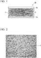
- FIG. 1 is a drawing schematically illustrating a cross-section of a sheet for a pressure sensor according to an embodiment of the present invention.
- FIG. 2 is an optical microscope photograph illustrating a planar view of a pressure-sensitive conductive layer according to an embodiment of the present invention.
- a pressure-sensitive film according to an embodiment of the present invention is described below using FIG. 1 and FIG. 2 .
- a pressure sensor sheet 10 includes a first electrode sheet 1a, a second electrode sheet 1b, and a flocculent pressure-sensitive conductive layer 3 composed of tangled conductive fibers 2, which is disposed between the first electrode sheet 1a and the second electrode sheet 1b and undergoes a change in resistance value when compressed.
- the conductive fibers 2 extend along a direction parallel to the two electrode sheets, and are stacked in the perpendicular direction.
- the pressure-sensitive conductive layer 3 has spaces between the conductive fibers 2 that constitute the layer.
- the conductive fibers may be a polymer material having a conductive material dispersed therein.
- the conductive material may be composed of one type or a plurality of types of fine particles.
- the term fine particles refers to nano-size nanomaterials or pico-size picomaterials, and means particles smaller than millimeter size.
- the flocculent pressure-sensitive conductive layer 3 composed of the tangled conductive fibers 2 is compressed, and therefore the conductive fibers 2 overlap in a dense arrangement.
- the contact surface area between the conductive fibers 2 and the first electrode sheet 1a and the second electrode sheet 1b increases.
- the shapes of the conductive fibers 2 themselves also undergo deformation.
- the pressure is weakened, the overlaps of the conductive fibers 2 become more sparse, the contact surface area between the conductive fibers 2 and the first electrode sheet 1a and the second electrode sheet 1b decreases, and the shapes of the conductive fibers 2 return to their original state.
- the changes in pressure are measured by the change in the resistance value between the first electrode sheet 1a and the second electrode sheet 1b that accompanies the above changes.
- the pressure sensor sheet 10 there are many factors that contribute to the change in resistance value, and the sheet can respond with good sensitivity even to extremely small changes in the applied pressure.
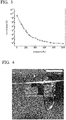
- FIG. 3 is a graph illustrating the change in the resistance value relative to the pressure applied to the pressure sensor sheet 10.
- the pressure sensor sheet 10 exhibits almost no conductivity, with a resistance value in the order of 10 10 ⁇ between the first electrode sheet 1a and the second electrode sheet 1b.
- the overlaps between the conductive fibers 2 strengthen, and the pressure sensor sheet 10 exhibits a resistance value in the order of 10 2 ⁇ between the first electrode sheet 1a and the second electrode sheet 1b. This is because the contact surface area between the conductive fibers 2 and the first electrode sheet 1a and the second electrode sheet 1b increases. In other words, the pressure sensor sheet 10 exhibits changes in the resistance value across a broad range from the order of 10 2 ⁇ to the order of 10 10 ⁇ .
- the change in the resistance value upon application of a weak pressure of 0 to 200 Pa is extremely marked.
- the pressure sensor sheet 10 can function as a sensor with high sensitivity even relative to small pressure changes.
- the conductive fibers 2 extend mainly along directions perpendicular to the direction of pressure application.
- FIG. 1 which illustrates the pressure sensor sheet 10 from a cross-sectional view
- the conductive fibers 2 are aligned mainly in parallel with the two electrode sheets.
- the pressure sensor sheet 10 because the response does not change greatly relative to expansion and contraction in directions parallel to the two electrode sheets, substantially the same response can be obtained in the case where pressure is applied in a bent state, and the case where pressure is applied in an extended state. In other words, the pressure sensor sheet 10 can perform high-precision measurements with minimal measurement noise even for pressure changes in dynamic regions. This type of high-precision measurement has been impossible to achieve with good sensitivity using conventional pressure sensor sheets formed, for example, by dispersing conductive particles in a rubber.
- FIG. 4 is a photograph showing a state in which pressure sensor sheet has been folded and a weight has then been placed on top of the sheet.
- FIG. 5 is a graph illustrating the change in resistance value when the weight shown in FIG. 4 is removed.
- a voltage of 2 V was applied between the two electrode sheets.
- a 0.4 g weight was placed on the pressure sensor sheet 3 seconds after the start of measurements, and this 0.4 g weight was removed from the pressure sensor sheet 8 seconds after the start of measurements.
- a 1.6 g weight was placed on the pressure sensor sheet 14 seconds after the start of measurements, and this 1.6 g weight was removed from the pressure sensor sheet 20 seconds after the start of measurements.
- a change in the resistance value of the pressure sensor sheet 10 occurs even when a pressure is applied with the sheet in a folded state. Further, there is a difference in the amount of current flow for the placements of the 0.4 g weight and the 1.6 g weight, indicating that the pressure sensor sheet 10 is able to detect even small differences in pressure.
- the conductive fibers 2 are tangled with spaces therebetween. As a result, light can pass through those spaces. Observation of the surface state while a pressure is being applied, measurements using light, or the application of light-based stimulus can be performed at the same time as the pressure application.
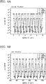
- FIG. 6A and FIG. 6B illustrate the results when a pressure of 2 kPa, 300 Pa or 80 Pa is applied repeatedly for 1,000 cycles to the pressure sensor sheet 10.
- FIG. 6A represents the results for the first 10 cycles
- FIG. 6B represents the results for the last 10 cycles.
- the results of FIGS. 6A and 6B indicate that no significant difference in the signal intensity occurs between the first 10 cycles and the last 10 cycles. In other words, the pressure sensor sheet 10 has superior repetition reproducibility.
- first electrode sheet 1a and the second electrode sheet 1b There are no particular limitations on the first electrode sheet 1a and the second electrode sheet 1b.
- a stretched sheet prepared by a method such as metal rolling may be used, or a sheet prepared by using vacuum deposition or sputtering or the like to form a layer of a metal or a transparent electrode or the like on a thin-film substrate may be used.
- transparent electrode typically used materials such as ITO, IZO and AZO may be used.
- a transparent electrode may also be formed by forming an extremely thin film of metal by vacuum deposition or sputtering or the like.
- the first electrode sheet 1a and the second electrode sheet 1b are preferably transparent electrodes.
- the conductive fibers 2 have spaces therebetween, allowing the transmission of light. Accordingly, by making the electrodes transparent, a pressure sensor sheet that transmits light can be obtained. This enables the location of the pressure measurement to be observed through the pressure sensor sheet. Further, the development of numerous other measurements becomes possible, such as simultaneously performing the pressure measurement and a measurement of light from above the pressure sensor sheet.
- the thickness of the film substrate is preferably at least 1 ⁇ m but not more than 15 ⁇ m, and is more preferably at least 1 ⁇ m but not more than 5 ⁇ m. Provided the film substrate is at least 1 ⁇ m, the film substrate can be produced stably, and sufficient film strength can be achieved. On the other hand, provided the thickness is not more than 15 ⁇ m, the pressure sensor sheet 10 exhibits substantially the same resistance value when the metal sheet is bent, and when the metal sheet is extended from a bent state using the same bend radius. Accordingly, a pressure sensor sheet 10 can be obtained that can satisfactorily accommodate operations such as bending and extending.
- the pressure sensor sheet 10 exhibits almost no change in the resistance value between a bent state and an extended state.
- the pressure sensor sheet 10 can be imparted with sensitivity only to pressure in the perpendicular direction, and the noise when the sheet is used in regions exposed to operations such as bending or extending is reduced, meaning a high degree of sensitivity can be maintained.
- Examples of materials that can be used as the film substrate include polyethylene terephthalate (PET), polyimide (PI), polyvinyl chloride (PVC), polycarbonate (PC), polyethylene naphthalate (PEN) and polyether ether ketone (PEEK).
- PET polyethylene terephthalate
- PI polyimide
- PVC polyvinyl chloride
- PC polycarbonate
- PEN polyethylene naphthalate
- PEEK polyether ether ketone
- metals or the like that can be used for the vacuum deposition or sputtering or the like include Au, Ag, Cu, Cr, Ti, Al, In, Sn, or laminated layers of these metals, and examples of transparent conductive materials that may be used include ITO and PEDOT/PSS.
- the first electrode sheet 1a or the second electrode sheet 1b preferably has air permeability.
- air permeability means the sheets do not completely block the passage of gases.
- the air permeability of the first electrode sheet 1a or the second electrode sheet 1b may be achieved by forming very fine holes in the first electrode sheet 1a or the second electrode sheet 1b, or the first electrode sheet 1a or the second electrode sheet 1b may be formed on a film having air permeability.
- the first electrode sheet 1a and the second electrode sheet 1b also both have air permeability.
- the entire pressure sensor sheet 10 can be imparted with air permeability.
- the pressure sensor sheet 10 is able to measure pressures acting upon the body surface without inhibiting the dissipation of moisture from the skin. This enables the development of a measurement system that causes no discomfort and suffers no defects even during long-term installation.
- the thicknesses of the first electrode sheet 1a and the second electrode sheet 1b are preferably substantially equal.
- the thicknesses of the first electrode sheet 1a and the second electrode sheet 1b are substantially equal, then the strain that acts upon the pressure-sensitive conductive layer 3 when the pressure sensor is subjected to bending can be reduced as far as possible. Consequently, the occurrence of errors in the measured pressure value caused by bending of the pressure sensor sheet 10 can be suppressed.
- the conductive fibers 2 that constitute the pressure-sensitive conductive layer 3 at least a portion of the fibers in those portions contacting the first electrode sheet 1a or the second electrode sheet 1b are preferably bound to the first electrode sheet 1a or the second electrode sheet 1b.
- bound means that among the conductive fibers 2, those conductive fibers 2 that contact the first electrode sheet 1a or the second electrode sheet 1b adhere naturally to the first electrode sheet 1a or the second electrode sheet 1b without the application of any external energy.
- the shapes of the conductive fibers 2 change, and the fibers bind to the first electrode sheet 1 a or the second electrode sheet 1b. If the state of the connection between the conductive fibers 2 and each of the electrode sheets is unstable, then a large amount of noise tends to occur when measurements are performed under weak pressure.
- the connection state becomes extremely stable. As a result, low-noise measurements can be performed using the pressure sensor sheet 10.
- the conductive fibers 2 that constitute the pressure-sensitive conductive layer 3 are preferably bound, at least partially, to both the first electrode sheet 1a and the second electrode sheet 1b. This leads to a structurally stable conductive path formed by the first electrode sheet 1a, the pressure-sensitive conductive layer 3 and the second electrode sheet 1b. Further, this structural stability improves the stability of the electrical state. Accordingly, measurements with even lower noise can be performed using the pressure sensor sheet 10.
- the pressure sensor sheet 10 can be formed extremely easily.
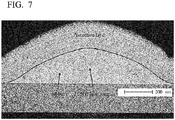
- FIG. 7 is a high-resolution cross-sectional transmission electron microscope image (TEM image) illustrating conductive fibers 2 bound to a substrate when the conductive fibers 2 are sprayed onto the substrate using an electrospinning deposition method.
- TEM image transmission electron microscope image
- the pressure sensor sheet preferably also has a second pressure-sensitive conductive layer composed of tangled second conductive fibers between the pressure-sensitive conductive layer 3 and the second electrode 1b, wherein at least a portion of the conductive fibers 2 in those portions contacting the first electrode sheet 1a are preferably bound to the first electrode sheet 1a, and at least a portion of the second conductive fibers in those portions contacting the second electrode sheet 1b are preferably bound to the second electrode sheet 1b.
- the second conductive fibers that constitute the second pressure-sensitive conductive layer may be the same as the conductive fibers described below. However, the same conductive fibers need not necessarily be used, meaning the conductive fibers and the second conductive fibers may be different.
- the pressure-sensitive conductive layer and the second pressure-sensitive conductive layer are preferably adhered together. Further, the pressure-sensitive conductive layer and the second pressure-sensitive conductive layer are preferably bound together. Adhering the pressure-sensitive conductive layer and the second pressure-sensitive conductive layer improves the structural stability of the pressure sensor sheet 10. This is accompanied by greater stability in the electrical state, making low-noise measurements possible. Furthermore, binding the pressure-sensitive conductive layer and the second pressure-sensitive conductive layer enables greater stability in the electrical state without electrically inhibiting the pressure-sensitive conductive layer and the second pressure-sensitive conductive layer, making measurements with even lower noise possible.
- adhere may describe either a self-organized bonding described as "binding” in the present description, or some other form of bonding that uses an adhesive or the like.
- the pressure-sensitive conductive layer 3 may contain not only the conductive fibers 2, but also mixed non-conductive fibers not shown in the drawings. By adjusting the mixing ratio between the conductive fibers 2 and the non-conductive fibers in the pressure-sensitive conductive layer 3, the sensitivity of the pressure sensor sheet 10 can be adjusted easily. Methods that may be used to lower the sensitivity of the pressure sensor sheet 10 and enable measurements to be performed up to high pressure include a method in which the mass ratio of the conductive material is lowered, and a method in which the conductive fibers 2 are thickened to increase the rigidity. However, reducing the mass ratio of the conductive material makes it difficult to obtain uniform resistance values. On the other hand, if the conductive are thickened, then the flexibility of the pressure sensor sheet 10 tends to be lost.
- the relationship between the pressure and the resistance value can be controlled with high precision.
- the pressure sensor sheet 10 can be prepared to best match the changes in pressure that are to be measured, meaning the sheet can be applied to all manner of applications.
- the thickness of the pressure-sensitive conductive layer 3 is preferably smaller than the combined thickness of the first electrode sheet 1a and the second electrode sheet 1b, and is preferably smaller than the thickness of either one of the first electrode sheet 1a and the second electrode sheet 1b.
- the rigidity of the sheet relative to bending must be suppressed to low levels, and the stress on the electrodes must also be suppressed.
- the sheet rigidity increases dramatically as the pressure-sensitive conductive layer 3 becomes thicker.
- the stress at the interfaces between the conductive fibers 2 and each of the electrode sheets also increases, meaning the stable connection between the conductive fibers 2 and the electrode sheets is more easily destroyed.
- the strain at the interfaces between the conductive fibers 2 and the electrode sheets is suppressed to approximately half of the strain at the electrode sheet outer surfaces, and unexpected faults during flexion of the electrode sheets and changes in the precision can be suppressed to low levels.
- the thickness of the pressure-sensitive conductive layer 3 is smaller than the thickness of either one of the first electrode sheet 1a and the second electrode sheet 1b, then strain at the connection portions between the conductive fibers 2 and each of the electrodes can be suppressed as low as possible.
- the thickness of the pressure-sensitive conductive layer 3 is preferably at least 2 times, but not more than 100 times, the diameter of the conductive fibers 2.
- the pressure-sensitive conductive layer 3 undergoes a reduction in the resistance value when the contact between the conductive fibers 2 increases due to pressure. This contact between the conductive fibers 2 is one of the principles that enables the pressure to be measured as a resistance value.
- the thickness of the pressure-sensitive conductive layer 3 is preferably a thickness corresponding with 2 layers, or 3 layers or more, of the conductive fibers 2. In other words, the thickness of the pressure-sensitive conductive layer 3 is preferably at least 2 times the diameter of the conductive fibers 2.
- the number of overlapping layers of the conductive fibers 2 increases, and localized fluctuations in the resistance value across the electrode sheets can be suppressed.
- increasing the number of stacked layers also causes an increase in the bending rigidity of the pressure sensor sheet 10 and an increase in the resistance value.
- the thickness is preferably not more than 100 ⁇ m, and more preferably 10 ⁇ m or less. If the thickness of the pressure-sensitive conductive layer 3 is 100 ⁇ m or less, then the flexibility is excellent, the sheet can satisfactorily follow objects having complex shapes or moving objects, and the sheet is able to function as a high-sensitivity, flexible sheet for a pressure sensor. If the thickness is 10 ⁇ m or less, then satisfactory transparency can be maintained.
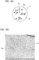
- FIG. 8A is a schematic illustration of the cross-section of the conductive fibers 2 that constitute the pressure sensor sheet 10 according to an embodiment of the present invention
- FIG. 8B is a high-resolution cross-sectional transmission electron microscope image (TEM image) of the conductive fibers 2 that constitute the pressure sensor sheet 10 according to an embodiment of the present invention.
- TEM image transmission electron microscope image
- the conductive fibers 2 preferably include at least a first conductive material 2a, a second conductive material 2b, and a polymer material 2c.
- the first conductive material 2a and the second conductive material 2b are dispersed uniformly within the conductive fibers 2. If these materials are not dispersed uniformly, then the conductive fibers 2 are unable to exhibit favorable conductivity.
- the term "conductive material” refers to a material having a conductive substance of microparticle size as a constituent element.
- the first conductive material 2a is preferably a filamentous conductive material
- the second conductive material 2b is preferably a particulate (including flake-like) conductive material.
- filamentous means that the length of the conductive material is at least 10 times the diameter of the material.
- the filamentous first conductive material 2a electrically connects particles of the particulate second conductive material 2b within the polymer material 2c.
- a weak pressure acts upon the pressure sensor sheet 10
- the conductivity through the filamentous first conductive material 2a changes, causing a reduction in the resistance value of the conductive fibers.
- the filamentous first conductive material 2a also has a secondary effect of improving the dispersion stability of the particulate second conductive material 2b in the production process for the conductive fibers 2.
- the mass ratio of the first conductive material 2a in the conductive fibers is smaller than the mass ratio of the second conductive material 2b enables an extremely large dynamic range for the change in resistance value upon pressure application. This is because by dispersing the second conductive material in a large mass ratio, a large reduction in the resistance value can be obtained when a high pressure acts upon the sheet.
- the first conductive material 2a is preferably carbon nanotubes or carbon nanohorns. Carbon nanotubes and carbon nanohorns have a certain degree of length, and therefore assist the conductivity between the dispersed particles of the second conductive material 2b, and it is thought that the shape of the carbon nanotubes or carbon nanohorns also assist uniform dispersion of the second conductive material 2b.
- Carbon nanotubes have a structure in which a single layer or multiple layers of graphene sheet having carbon atoms arranged in a hexagonal mesh have been rounded into a circular cylindrical shape.
- Single-walled nanotubes (SWNT), double-walled nanotubes (DWNT) or multi-walled nanotubes (MWNT) may be used.
- Single-walled nanotubes (SWNT) are preferable. This is because a more uniform material with better quality stability can be obtained, and because good dispersion stability can be more easily achieved.
- Carbon nanotubes can generally be produced by a laser ablation method, arc discharge method, thermal CVD method, plasma CVD method, gas phase method, or combustion method or the like, and carbon nanotubes produced using any of these types of methods may be used.
- the second conductive material 2b can use materials such as graphene, gold nanoflakes, silver nanoflakes, aluminum flakes, carbon black, gold nanoparticles, silver nanoparticles and copper nanoparticles.
- the second conductive material 2b is preferably graphene or carbon black, as graphene and carbon black exhibit extremely high conductivity and are stable.
- the first conductive material 2a is carbon nanotubes or carbon nanohorns
- the second conductive material 2b is graphene or carbon black.
- Conductive materials composed of carbon exhibit superior durability relative to oxygen and moisture, and are most suited to pressure-sensitive conductive layers 3 composed of fibers having a high specific surface area.
- the mass ratio of the first conductive material 2a is preferably smaller than the mass ratio of the second conductive material 2b.
- the mass ratio of second conductive material 2b : first conductive material 2a is preferably within a range from 3:1 to 25:1. Provided the ratio satisfies this range, the first conductive material 2a and the second conductive material 2b can be dispersed uniformly within the polymer material 2c, and conductive fibers 2 of satisfactory conductivity can be ensured.
- the mass ratio of the first conductive material 2a within the conductive fibers is preferably from 0.5 wt% to 5 wt%, and the mass ratio of the second conductive material 2b is preferably within a range from 5 wt% to 50 wt%.
- the second conductive material 2b is the main contributor to the conductivity, ensuring that the mass ratio of the second conductive material 2b is larger than the mass ratio of the first conductive material 2a can increase the degree of change in the resistance value of the pressure sensor sheet 10, thereby increasing the sensitivity of the pressure sensor sheet 10.
- the pressure sensor sheet 10 functions with higher sensitivity.
- the mass ratio of the combination of the first conductive material 2a and the second conductive material 2b within the conductive fibers 2 is preferably from 20 wt% to 50 wt%, and more preferably from 30 wt% to 40 wt%.
- the polymer material 2c may use a typically used elastomer such as a fluorine-based rubber, urethane-based rubber or silicon-based rubber, or may use a polymer material other than an elastomer, such as an acrylic, nylon or polyester.
- a typically used elastomer such as a fluorine-based rubber, urethane-based rubber or silicon-based rubber
- a polymer material other than an elastomer such as an acrylic, nylon or polyester.
- the use of an elastomer as the polymer material 2c of the conductive fibers 2 is preferable. Elastomers are flexible, and exhibit extremely little change in mechanical properties even when repeatedly subjected to large strain. When pressure is applied, large strain develops in the overlapping portions of the conductive fibers 2, but by using an elastomer as the base material, a combination of superior flexibility and superior durability can be achieved for the pressure sensor sheet.
- the polymer material 2c may be altered in accordance with the intended use of the pressure sensor sheet 10.
- the diameter of the conductive fibers 2 is preferably smaller than the thickness of the first electrode sheet 1a and the second electrode sheet 1b. If the diameter of the conductive fibers 2 is larger than each of the electrode sheets, then each electrode sheet becomes more prone to localized deformation that follows the surface of the conductive fibers 2. As a result, the state of contact between the conductive fibers 2 and the electrode sheets upon pressure application becomes irregular. Ensuring that the diameter of the conductive fibers 2 is smaller than the thickness of the first electrode sheet 1a and the second electrode sheet 1b enables suppression of any fluctuations in the change in the resistance value under pressure that may be caused by this type of irregularity in the contact state.
- the diameter of the conductive fibers 2 is preferably from 100 nm to 10 ⁇ m, and more preferably from 200 nm to 2,000 nm. If the diameter of the conductive fibers 2 changes, then the rigidity and specific surface area of the conductive fibers and the contact surface area between the conductive fibers also change, causing a change in the sensitivity of the pressure sensor sheet 10. If the diameter is from 200 nm to 2,000 nm, then the sheet can function as a pressure sensor sheet of satisfactory sensitivity. Extremely fine conductive fibers 2 have low strength, whereas extremely thick conductive fibers 2 have high rigidity and impair the flexibility of the sensor sheet. Accordingly, by ensuring that the diameter of the conductive fibers 2 is within the above range, a combination of favorable sensitivity and flexibility can be achieved.
- FIG. 9 is a schematic cross-sectional view of a pressure sensor 100 according to an embodiment of the present invention.
- the pressure sensor includes the pressure sensor sheet 10, and a transistor 20 connected to at least one of the first electrode sheet 1a and the second electrode sheet 1b of the pressure sensor sheet 10.
- a pressure sensor sheet 10 having superior flexibility is suited to measurements on surfaces having fine undulations. Accordingly, in order to enable measurement of a pressure distribution with high spatial resolution, the electrodes are divided into a multitude of segments, with a plurality of measurement points disposed on a single pressure sensor sheet 10. In order to enable the plurality of electrode segments to be arranged in a matrix, switching of each of the electrode segments with a transistor is effective. This enables a highly functional pressure sensor to be obtained.
- the pressure sensor 100 when the resistance value of the pressure sensor sheet 10 changes, the amount of current flowing through the transistor 20 changes, and externally outputting a signal corresponding with that current value enables the sensor to function as a pressure sensor 100.
- a field effect transistor such as that illustrated in FIG. 9 is used as the transistor 20
- pressure application causes a reduction in the resistance value of the pressure sensor sheet 10
- the potential difference between a source electrode 21 and a drain electrode 22 increases, and the size of the resultant current flow also increases. If the relationship between the pressure applied to the pressure sensor sheet 10 and the current is ascertained in advance, then the amount of pressure applied to the pressure sensor 100 can be detected by reading the change in the signal output corresponding with the current.
- the total thickness of the pressure sensor 100 is preferably not more than 100 ⁇ m. If the sensor is thinner than 100 ⁇ m, then it can function as an extremely flexible pressure sensor, capable of following complex shapes.
- the transistor 20 is preferably an organic transistor.
- the transistor There are no particular limitations on the construction of the transistor, and for example, a field effect transistor such as that illustrated in FIG. 9 may be used.
- the on-resistance of an organic transistor is in the order of M ⁇ , and therefore in order to cause a change in the potential difference between the source electrode 21 and the drain electrode 22, it has been thought that the change in resistance of the pressure sensor sheet 10 upon pressure application should preferably be in the order of several M ⁇ to 100 k ⁇ .
- the pressure sensor sheet 10 according to the present embodiment exhibits changes in the resistance value across a broad range from the order of 10 2 ⁇ to the order of 10 10 ⁇ , and can therefore be used very favorably.
- a method for producing a sheet for a pressure sensor includes jetting a dispersion-based liquid containing a polymer material and a conductive material onto an electrode sheet using an electrospinning deposition method, thereby forming a pressure-sensitive conductive layer composed of tangled conductive fibers.
- the electrospinning method enables the conductive fibers to be bound to the first electrode sheet without using any special adhesive or performing any special process, and is therefore ideal for forming a pressure-sensitive conductive layer composed of very fine fibers.
- the method for producing a sheet for a pressure sensor preferably includes a first step of mixing a first conductive material and an ionic liquid with a solvent to obtain a first dispersion system in which the first conductive material is dispersed within the solvent, a second step of mixing a second conductive material with a solvent to obtain a second dispersion system in which the second conductive material is dispersed within the solvent, a third step of mixing the first dispersion system and the second dispersion system to obtain a third dispersion system, a fourth step of adding an elastomer to the third dispersion system and stirring to obtain a fourth dispersion system, and a fifth step of jetting the fourth dispersion system onto a first electrode sheet using an electrospinning deposition method, thereby forming a pressure-sensitive conductive layer composed of tangled conductive fibers.
- This method for producing a sheet for a pressure sensor is described below in further detail, based on the preferred production conditions for each of the first to fifth steps.
- a first conductive material and an ionic liquid are mixed with a solvent to obtain a first dispersion system in which the first conductive material is dispersed within the solvent.
- the solvent is preferably 4-methyl-2-pentanone.
- carbon nanotubes, carbon nanohorns, or metal nanowires or the like can be used.
- EMIBF 4 or DEMEBF 4 or the like can be used as the ionic liquid.
- the ionic liquid has the role of preventing aggregation of the first conductive material.
- a shearing force is preferably applied.
- a ball mill, roller mill, vibration mill, or jet mill or the like may be used.
- the first conductive material is preferably added to a first solvent in an amount within a range from 0.2 wt% to 20 wt%. If the proportion of the first conductive material is less than 0.2 wt%, then achieving favorable conductivity becomes difficult. On the other hand, if the proportion of the first conductive material exceeds 20 wt%, then achieving uniform dispersion of the material is difficult.
- the ionic liquid is preferably added to the first solvent in an amount within a range from 1 wt% to 20 wt%. If the proportion of the ionic liquid is less than 1 wt%, then aggregation of the first conductive material cannot be satisfactorily suppressed. On the other hand, if the proportion of the ionic liquid exceeds 20 wt%, then the excess ionic liquid must be removed.
- a second conductive material is mixed with a solvent to obtain a second dispersion system in which the second conductive material is dispersed within the solvent.
- the solvent may employ the same solvent as that used in the first step.
- the second conductive material graphene, gold nanoflakes, silver nanoflakes, aluminum flakes, carbon black, gold nanoparticles, silver nanoparticles, or copper nanoparticles or the like may be used.
- a shearing force is preferably applied during the second step, and the same device as that used in the first step may be used.
- an ionic liquid may also be added and mixed, in a similar manner to the first step.
- the second conductive material is preferably added to a second solvent in an amount within a range from 10 wt% to 80 wt%, and more preferably within a range from 6 wt% to 8 wt%. If the proportion of the second conductive material is less than 10 wt%, then achieving favorable conductivity becomes difficult. On the other hand, if the proportion of the second conductive material exceeds 80 wt%, then achieving uniform dispersion of the material is difficult.
- the first dispersion system and the second dispersion system are mixed to obtain a third dispersion system.
- the solvents used in the first step and the second step are the same, it could be considered that the first conductive material and the second conductive material could simply be added to the solvent in a single batch.
- the first conductive material and the second conductive material are added in a single batch, then achieving uniform dispersion of each of the materials in the solvent tends to become more difficult. Accordingly, it is important that the first dispersion system and the second dispersion system are prepared separately, and are subsequently mixed together to obtain the third dispersion system.
- stirring is preferably performed to ensure thorough mixing of the first dispersion system and the second dispersion system. Mechanical stirring is adequate for this stirring, and heat or the like need not be applied.
- an elastomer is added to the third dispersion system and stirred to obtain a fourth dispersion system.
- a typically used elastomer such as a fluorine-based rubber, urethane-based rubber or silicon-based rubber may be used as the elastomer.
- other polymer materials may also be used, such as an acrylic, nylon or polyester.
- the mass ratio of the elastomer in the fourth dispersion system is preferably from 10 wt% to 50 wt%.
- the mass ratio of the first conductive material in the fourth dispersion system is preferably from 0.1 wt% to 5 wt%, and the mass ratio of the second conductive material is preferably from 0.5 wt% to 25 wt%.
- the mass ratio of the elastomer is less than 10 wt%, then solvent evaporation during the electrospinning process may take too long, and favorable fiber formation may become difficult. On the other hand, if the mass ratio of the elastomer exceeds 50 wt%, then the viscosity increases, making it difficult to achieve uniform dispersion of the first conductive material and the second conductive material.
- the sensitivity and the range of resistance values for the pressure sensor sheet can be modified.
- the stirring in the fourth step is preferably performed for at least 4 hours. Adding the elastomer increases the viscosity of the dispersion system, and therefore performing thorough stirring is necessary.
- the fourth dispersion system is subjected to electrospinning deposition to form a pressure-sensitive conductive layer having tangled conductive fibers.
- the electrospinning deposition method is described using FIG. 10 .
- the fourth dispersion system 4 inside a syringe 5 is forced from the syringe while a high voltage is applied between the needle 5a of the syringe 5 and the first electrode sheet 1a. At this time, because of the potential difference between the needle 5a and the first electrode sheet 1a, the fourth dispersion system 4 is drawn rapidly from the syringe 5 and sprayed toward the first electrode sheet 1a. This sprayed fourth dispersion system 4 is deposited on the top of the first electrode sheet 1a in a flocculent form as the conductive fibers 2.
- the solvent of the fourth dispersion system 4 evaporates almost completely between the needle 5 a and the first electrode sheet 1a, and therefore the majority of the solvent within the conductive fibers 2 has evaporated at the point the fibers are deposited on the first electrode sheet 1a in a flocculent form.
- the solvent within the conductive fibers 2 deposited on the first electrode sheet 1a has not evaporated completely.
- this residual solvent within the conductive fibers 2 evaporates on the first electrode sheet 1a.
- the shape of the conductive fibers 2 changes to a kamaboko-type shape illustrated in FIG. 7 , thereby binding together the first electrode sheet 1a and the conductive fibers 2.
- the first electrode sheet 1a and the conductive fibers 2 can be bound without requiring the use of extra adhesive or the like, and a pressure sensor of higher sensitivity can be produced.
- the distance between the needle 5a and the first electrode sheet 1a is preferably within a range from 10 cm to 50 cm.
- the method may further include a step of jetting a dispersion-based liquid containing a polymer material and a conductive material onto the second electrode sheet using an electrospinning deposition method, thereby forming second a pressure-sensitive conductive layer composed of tangled conductive fibers, and a step of binding together the pressure-sensitive conductive layer formed on the first electrode sheet and the second pressure-sensitive conductive layer formed on the second electrode sheet.
- the pressure-sensitive conductive layer and the second pressure-sensitive conductive layer are each composed of tangled conductive fibers, simply bringing the pressure-sensitive conductive layer and the second pressure-sensitive conductive layer into contact causes the respective conductive fibers to become tangled and bind together, producing satisfactory structural stability.
- the fourth dispersion system 4 is pulled rapidly from the fine aperture of the needle 5a due to the potential difference. At this time, the fourth dispersion system 4 is subjected to shearing forces, and therefore any aggregates of the first conductive material or the second conductive material that had not been completely dispersed within the fourth dispersion system are eliminated. For this reason, the aperture of the needle 5a is preferably within a range from 0.2 mm to 2 mm.
- the pressure-sensitive conductive layer is preferably formed by placing the respective raw materials in two syringes, and performing simultaneous electrodeposition spinning. If the conductive fibers 2 and the non-conductive fibers are formed by sequential deposition by electrodeposition spinning, then regions with conductivity and regions without conductivity may develop within the pressure-sensitive conductive layer, resulting in a lack of uniformity in the conductivity.
- the fifth step is performed within 24 hours of completing the fourth step.
- the fifth step is more preferably performed within 12 hours of the fourth step. If the fourth dispersion system is left to stand for longer than 24 hours, then the dispersed first conductive material and second conductive material may re-aggregate. If the fourth dispersion system is left to stand for longer than 12 hours, then even using the shearing forces that occur as the dispersion system passes through the fine aperture of the needle 5a, re-dispersion of the first conductive material and the second conductive material may become impossible.
- a first step 0.6 wt% of carbon nanotubes and 2 wt% of an ionic liquid were mixed with a solvent of 4-methyl-2-pentanone.
- a high-pressure jet mill homogenizer 60 MPa, Nano-jet pal, JN10, manufactured by Jokoh Co., Ltd.
- a first dispersion system was obtained in which the carbon nanotubes were dispersed uniformly within the solvent composed of 4-methyl-2-pentanone.
- the first dispersion system and the second dispersion system are stirred for 2 hours with a stirrer, thus obtaining a third dispersion system.
- a fluorine-based rubber G-912 product name, manufactured by Daikin Industries, Ltd.
- a fluorine-based rubber G-912 product name, manufactured by Daikin Industries, Ltd.
- the proportions of the elastomer, the carbon nanotubes and the graphene within the fourth dispersion system were 0.3 wt%, 3 wt% and 25 wt% respectively.
- the obtained fourth dispersion system was placed in a syringe having a needle aperture of 20 nm, and an electrode sheet was installed in a position 25 cm from the tip of the needle.
- a voltage of 25 kV was then applied between the needle and the electrode sheet, and the fourth dispersion system was discharged from the syringe at a rate of 10 ⁇ l/min, thus forming a pressure-sensitive conductive layer having a size of 20 cm ⁇ 20 cm square and composed of tangled conductive fibers on the electrode sheet by electrospinning deposition.
- the thickness of the thus obtained pressure-sensitive conductive layer was 4 ⁇ m.
- the electrode sheet was prepared by layering 50 nm of Au on a PET film of 1.4 ⁇ m.
- the diameter of the conductive fibers was 300 nm to 400 nm, the mass ratio of the first conductive material within the conductive fibers was 1 wt%, and the mass ratio of the second conductive material was 12 wt%.
- FIG. 11 is a photograph of the pressure sensor sheet of Example 1. The total thickness of this pressure sensor sheet was 7 ⁇ m.
- Example 2 with the exception of the fifth step, a pressure sensor was prepared using the same production method as that of Example 1.
- another syringe was also prepared containing a solution that differed from the fourth dispersion system only in not containing any conductive material.
- the fourth dispersion system and the solution containing no conductive materials were then discharged simultaneously from the two syringes, forming a pressure-sensitive conductive layer having a size of 20 cm ⁇ 20 cm square on an electrode sheet by electrospinning deposition.
- the diameters of the syringe needles, the distance between the needles and the electrode sheet, and the voltage applied between the needles and the electrode sheet were the same as Example 1.
- the thickness of the thus obtained pressure-sensitive conductive layer was 4 ⁇ m, and the non-conductive fibers were mixed into the pressure-sensitive conductive layer with a ratio of conductive fibers : non-conductive fibers of 1:1.
- the electrode sheet was prepared by layering 50 nm of Au on a PET film of 1.4 ⁇ m.
- the diameter of the conductive fibers was 300 nm to 400 nm, the mass ratio of the first conductive material within the conductive fibers was 1 wt%, and the mass ratio of the second conductive material was 12 wt%.
- the total thickness of this pressure sensor sheet was 7 ⁇ m.
- FIG. 12 is a graph illustrating the change in the resistance value relative to the pressure applied to the pressure sensor sheets of Example 1 and Example 2.
- the pressure sensor sheet of Example 1 exhibited a change in the resistance value within a range from the order of 10 2 ⁇ to the order of 10 10 ⁇
- the pressure sensor sheet of Example 2 exhibited a change in the resistance value within a range from the order of 10 4 ⁇ to the order of 10 10 ⁇ , with both pressure sensor sheets exhibiting extremely large changes in the resistance value relative to applied pressure.
- the pressure sensor sheet of Example 2 Compared with the pressure sensor sheet of Example 1, the pressure sensor sheet of Example 2 exhibited a smaller change in the resistance value and different sensitivity. This is because the pressure sensor sheet of Example 2 included a mixture of conductive fibers and non-conductive fibers, resulting in a duller sensitivity compared with the pressure sensor sheet of Example 1 composed of only conductive fibers. In other words, by changing the mixing ratio between the conductive fibers and the non-conductive fibers in the pressure sensor sheet, the sensitivity of the pressure sensor sheet can easily be adjusted.
- Example 3 with the exception of forming an organic field effect transistor on a PI film of thickness 12.5 ⁇ m, a pressure sensor was prepared using the same production method as Example 1. The thickness of the obtained pressure sensor was 29 ⁇ m.
- Example 4 with the exception of forming an organic field effect transistor on a PI film of thickness 75 ⁇ m, a pressure sensor was prepared using the same production method as Example 1. The thickness of the obtained pressure sensor was 154 ⁇ m.
- FIG. 13 is a graph illustrating the change in the resistance value relative to the bend radius, when the pressure sensor sheets of Example 1, Example 3 and Example 4 were subjected to bending.
- Examples 1 and 2 exhibited the same resistance value at the same bend radius even when exposed to bending and extending, confirming that the sheets were able to satisfactorily accommodate bending and extending and the like, and were able to function as flexible pressure sensor sheets.
- the pressure sensor sheet of Example 1 exhibited no change in the resistance value from the extended state, even in a state where the bend radius was close to 0mm (a state in which the pressure sensor sheet was almost folded in two). In other words, it was evident that the pressure sensor sheet undergoes almost no reaction to pressure applied parallel to the sheet. Hence, only pressure applied in a direction perpendicular to the pressure sensor sheet can be measured with good precision, meaning the sheet is particularly suitable as a pressure sensor sheet for objects having complex shapes or objects that are exposed to movements such as bending and extending.
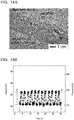
- FIG. 14A is a photograph showing the pressure sensor sheet of Example 1 installed on an artificial blood vessel formed from a silicone tube
- FIG. 14B illustrates the measurement results when the artificial blood vessel was pulsed.
- a blood vessel pulse was simulated by feeding a liquid through the artificial blood vessel at alternating pressures of 80 mmHg and 120 mmHg. As illustrated in FIG. 14B , it is clear that the resulting electric current changed in accordance with the pulses. In other words, the sheet was able to suitably follow a moving object, and was capable of measuring, with superior sensitivity, a pressure applied to the moving object.
- Example 6 differs in that the first step of Example 1 was not performed.
- the pressure sensor sheet of Example 6 differed from the pressure sensor sheet of Example 1 in that only graphene was used as the conductive material within the conductive fibers.
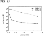
- FIG. 15 is a graph illustrating the change in the resistance value relative to the pressure applied to the pressure sensor sheets according to Example 1 and Example 6. Although the pressure sensor sheet of Example 6 exhibited inferior sensitivity of the change in resistance value relative to applied pressure compared with the pressure sensor sheet of Example 1, it was still capable of functioning satisfactorily as a pressure sensor.
Landscapes
- Engineering & Computer Science (AREA)
- Physics & Mathematics (AREA)
- General Physics & Mathematics (AREA)
- Mechanical Engineering (AREA)
- Textile Engineering (AREA)
- Force Measurement Appropriate To Specific Purposes (AREA)
Abstract
Description
- The present invention relates to a sheet for a pressure sensor, a pressure sensor, and a method for producing a sheet for a pressure sensor.
- Priority is claimed on
Japanese Patent Application No. 2014-021488, filed February 6, 2014 - Due to the flexibility of the materials used, flexible electronics produced using organic semiconductors can be fit to the outer surfaces or insides of the human body. Consequently, the use of flexible electronics to obtain biological information directly from cells or tissues has been garnering much attention in recent years.
- Pressure sensors are attracting attention as one such application. A pressure sensor is a device that outputs an applied pressure as an electrical signal. Pressure sensors are widely used, for example, in artificial skin and robot operations and the like (Patent Document 1). These technologies continue to develop rapidly, and more precise data is now being demanded. In order to obtain more precise data, it is necessary for the pressure sensor to better fit the shape of the object being measured, and for the pressure sensor to be capable of better following movements such as bending and extending. Accordingly, thinner and more flexible pressure sensors are required.
- In order to realize such pressure sensors, the types of investigations described below are being pursued.
-
Patent Document 2 discloses, as a simple matrix pressure-sensitive sensor, a pressure-sensitive sheet obtained by vertically and horizontally weaving a pressure-sensitive wire composed of a cylindrical elastic body, a conductive layer formed as a layer on the outer peripheral surface of the cylindrical elastic body, and a dielectric layer formed on top of the conductive layer. -
Patent Document 3 discloses an active matrix pressure-sensitive sensor that uses electrodes, a pressure-sensitive conductive sheet and a transistor, and also discloses a pressure-sensitive conductive sheet in which graphite is added to a silicon rubber. -
Patent Document 4 discloses a flexible pressure-sensitive sensor having a structure containing two or more layers, the sensor including a pressure-sensitive conductive sheet prepared by forming a resin coating film containing a conductive material on the surface of a rubber substrate. By using a structure containing two or more layers, the hysteresis of changes in the pressure-resistance can be improved. -
- Patent Document 1:
Japanese Unexamined Patent Application, First Publication No. 2013-136141 - Patent Document 2:
Japanese Unexamined Patent Application, First Publication No. 2008-170425 - Patent Document 3:
Japanese Unexamined Patent Application, First Publication No. 2013-068562 - Patent Document 4:
Japanese Unexamined Patent Application, First Publication No. 2012-145447 - However, the pressure sensor sheets disclosed in
Patent Documents 1 to 4 have thicknesses of several hundred µm to several mm. Accordingly, with these pressure sensor sheets, achieving satisfactory followability of objects having complex shapes or moving objects has been impossible, and precise data has been unobtainable. For example, the outer diameter of the cylindrical elastic body that acts as the substrate of the pressure-sensitive wire of the pressure sensor sheet disclosed inPatent Document 2 is 250 µmφ. The document discloses that in order to enable the sheet to function as a pressure sensor sheet, the thickness of the overall pressure sensor must be greater than this outer diameter. Further,Patent Document 3 discloses that the thickness of just the rubber substrate that represents one portion of the pressure sensor sheet must be in the order of mm. - Further, because these pressure sensor sheets exhibit insufficient change in resistance value relative to applied pressure, a small change in pressure cannot be satisfactorily reflected as an output signal. In other words, these pressure sensor sheets have been unable to obtain high-sensitivity data. For example,
Fig.3 ofPatent Documents 2 discloses that the change in the resistance value relative to applied pressure is a mere several hundred kΩ. - When a pressure sensor sheet prepared by incorporating a conductive material in a rubber substrate or a resin coating film is used, not only does the resistance value change upon pressure changes in a direction perpendicular to the pressure sensor sheet, but the resistance value also changes when the pressure sensor sheet stretches in a direction parallel to the sheet. The important change in resistance value which it is desirable to measure occurs in accordance with pressure changes in a direction perpendicular to the pressure sensor sheet. In contrast, changes in the resistance value accompanying stretching in a parallel direction are noise. Accordingly, when a conventional pressure sensor sheet is used, variations in the measurement results occur between the state where the pressure sensor sheet is bent, and the state where the sheet is extended. In other words, these pressure sensor sheets have been unable to achieve high-sensitivity measurement of the pressure applied to objects having complex shapes or moving objects.
- Moreover, active matrix pressure sensors require that a pressure-sensitive conductive layer and an electrode sheet are disposed on a transistor. However, because the pressure-sensitive conductive layer is formed from a black rubber, the bonding surface cannot be viewed visually following mounting of the pressure sensor. Further, when this type of pressure sensor sheet is mounted on a living body (for example, when mounted on the surface of the skin), the pressure-sensitive conductive layer, which is formed from an impermeable rubber, does not allow the transmission of moisture or air, and prevents heat dissipation by air flow. Accordingly, discomfort or inflammation of the skin or the like caused by lack of ventilation at the mounting location may sometimes occur.
- The present invention has been developed in light of the above circumstances, and has an object of providing an ultra thin sheet for a pressure sensor having superior flexibility and higher sensitivity, as well as providing a pressure sensor and a method for producing the sheet for a pressure sensor.
- In order to achieve the above object, the present invention adopts the aspects described below.
- (1) A sheet for a pressure sensor, including a first electrode sheet, a second electrode sheet, and a flocculent pressure-sensitive conductive layer composed of tangled conductive fibers which is disposed between the first electrode sheet and the second electrode sheet and undergoes a change in resistance value when compressed, wherein the conductive fibers extend along a direction parallel to the two electrode sheets and are stacked in a perpendicular direction, and the conductive fibers that constitute the pressure-sensitive conductive layer have spaces provided therebetween.
- (2) The sheet for a pressure sensor according to (1), wherein the conductive fibers contain a conductive material dispersed in a polymer material.
- (3) The sheet for a pressure sensor according to (2), wherein the conductive material is composed of a first conductive material and a second conductive material, the first conductive material is a filamentous conductive material, and the second conductive material is a particulate (including flake-like) conductive material.
- (4) The sheet for a pressure sensor according to (3), wherein the first conductive material is carbon nanotubes or carbon nanohorns, and the second conductive material is graphene or carbon black.
- (5) The sheet for a pressure sensor according to (3) or (4), wherein the mass ratio of the first conductive material within the conductive fibers is smaller than the mass ratio of the second conductive material.
- (6) The sheet for a pressure sensor according to any one of (1) to (5), wherein among the conductive fibers that constitute the pressure-sensitive conductive layer, at least a portion of the fibers in those portions contacting the first electrode sheet or the second electrode sheet are bound to the first electrode sheet or the second electrode sheet.
- (7) The sheet for a pressure sensor according to any one of (1) to (6), further containing a second pressure-sensitive conductive layer composed of tangled second conductive fibers between the pressure-sensitive conductive layer and the second electrode sheet, wherein at least a portion of the conductive fibers in those portions contacting the first electrode sheet are bound to the first electrode sheet, and at least a portion of the second conductive fibers in those portions contacting the second electrode sheet are bound to the second electrode sheet.
- (8) The sheet for a pressure sensor according to (7), wherein the pressure-sensitive conductive layer and the second pressure-sensitive conductive layer are adhered together.
- (9) The sheet for a pressure sensor according to any one of (2) to (7), wherein the polymer material is an elastomer.
- (10) The sheet for a pressure sensor according to any one of (1) to (9), wherein the first electrode sheet and the second electrode sheet are transparent electrodes.
- (11) The sheet for a pressure sensor according to any one of (1) to (10), wherein the pressure-sensitive conductive layer, when viewed from a direction perpendicular to the electrode sheets, has spaces in which no conductive fibers exist.
- (12) The sheet for a pressure sensor according to any one of (1) to (11), wherein the diameter of the conductive fibers is smaller than the thickness of the first electrode sheet and the second electrode sheet.
- (13) The sheet for a pressure sensor according to any one of (1) to (12), wherein the diameter of the conductive fibers is within a range from 100 nm to 10 µm.
- (14) The sheet for a pressure sensor according to any one of (1) to (13), wherein the thickness of the pressure-sensitive conductive layer is smaller than the combined thickness of the first electrode sheet and the second electrode sheet.
- (15) The sheet for a pressure sensor according to any one of (1) to (14), wherein the thicknesses of the first electrode sheet and the second electrode sheet are substantially equal.
- (16) The sheet for a pressure sensor according to any one of (1) to (15), wherein the first electrode sheet or the second electrode sheet has air permeability.
- (17) The sheet for a pressure sensor according to any one of (1) to (16), wherein the thickness of the pressure-sensitive conductive layer is at least 2 times, but not more than 100 times, the diameter of the conductive fibers.
- (18) The sheet for a pressure sensor according to any one of (1) to (17), wherein the thickness of the pressure-sensitive conductive layer is within a range from 0.5 µm to 100 µm.
- (19) The sheet for a pressure sensor according to any one of (1) to (18), wherein non-conductive fibers are mixed within the pressure-sensitive conductive layer.
- (20) A pressure sensor, wherein at least one electrode among the first electrode sheet and the second electrode sheet of the sheet for a pressure sensor according to any one of (1) to (19) is connected to a transistor.
- (21) A method for producing the sheet for a pressure sensor according to any one of (1) to (19), the method including jetting a dispersion-based liquid containing a polymer material and a conductive material onto a first electrode sheet using an electrospinning deposition method, thereby forming a pressure-sensitive conductive layer composed of tangled conductive fibers.
- (22) A method for producing a sheet for a pressure sensor, the method including a first step of mixing a first conductive material and an ionic liquid with a solvent to obtain a first dispersion system in which the first conductive material is dispersed within the solvent, a second step of mixing a second conductive material with a solvent to obtain a second dispersion system in which the second conductive material is dispersed within the solvent, a third step of mixing the first dispersion system and the second dispersion system to obtain a third dispersion system, a fourth step of adding a polymer material to the third dispersion system and stirring to obtain a fourth dispersion system, and a fifth step of jetting the fourth dispersion system onto a first electrode sheet using an electrospinning deposition method, thereby forming a pressure-sensitive conductive layer composed of tangled conductive fibers.
- (23) The method for producing a sheet for a pressure sensor according to (21) or (22), further including a step of jetting a dispersion-based liquid containing the polymer material and the conductive material onto a second electrode sheet using an electrospinning deposition method, thereby forming a second pressure-sensitive conductive layer composed of tangled conductive fibers, and a step of binding the pressure-sensitive conductive layer and the second pressure-sensitive conductive layer.
- The sheet for a pressure sensor according to one aspect of the present invention includes a first electrode sheet, a second electrode sheet, and a flocculent pressure-sensitive conductive layer composed of tangled conductive fibers which is disposed between these electrode sheets and undergoes a change in resistance value when compressed. The conductive fibers extend along a direction parallel to the electrode sheets, and are stacked in a perpendicular direction. Further, spaces exist between the conductive fibers that constitute the pressure-sensitive conductive layer. When the pressure applied to the pressure sensor sheet changes, the density of the flocculent tangled conductive fibers changes, and changes occur in the state of the stacking of the conductive fibers. When this stacking state changes, the resistance value between the first electrode sheet and the second electrode sheet changes. The conductive fibers have anisotropy in the direction parallel to, and in the direction perpendicular to, the two electrode sheets. The change in the resistance value in the stacking direction is extremely large relative to external forces in the perpendicular thickness direction, whereas the change in the resistance value caused by strain in the parallel direction is extremely small. When the sheet for a pressure sensor is subjected to a bending deformation, because the strain caused by the bending deformation is in a direction parallel to the electrode sheets, the change in resistance value caused by the bending deformation is small. In other words, measurement noise is minimal, meaning high-precision measurements are possible.
- In the sheet for a pressure sensor according to one aspect of the present invention, the conductive fibers may be prepared by dispersing a conductive material in a polymer material. Further, the conductive fibers may be composed of a polymer material having a first conductive material and a second conductive material dispersed therein, wherein this first conductive material is a filamentous conductive material, and the second conductive material is a particulate (including flake-like) conductive material. The filamentous first conductive material electrically connects particles of the particulate second conductive material within the polymer material. When a weak pressure acts upon the pressure sensor sheet, the conductivity through the filamentous first conductive material changes, causing a reduction in the resistance value of the conductive fibers. As a result of this effect, the sensor sensitivity at low pressures and the stability of the sensor sensitivity can be improved. The filamentous first conductive material also has a secondary effect of improving the dispersion stability of the particulate second conductive material in the fiber production process.
- Moreover, ensuring that the mass ratio of the first conductive material in the conductive fibers is smaller than the mass ratio of the second conductive material enables an extremely large dynamic range for the change in resistance value upon pressure application. This is because by dispersing the second conductive material in a large mass ratio, a large reduction in the resistance value can be obtained when a high pressure acts upon the sheet.
- In the sheet for a pressure sensor according to one aspect of the present invention, the first conductive material may be carbon nanotubes or carbon nanohorns, and the second conductive material may be graphene or carbon black. Conductive materials formed from carbon exhibit superior durability relative to oxygen and moisture, and are most suited to pressure-sensitive conductive layers composed of fibers having a high specific surface area.
- In the sheet for a pressure sensor according to one aspect of the present invention, at least a portion of the conductive fibers that constitute the pressure-sensitive conductive layer in those portions contacting the first electrode sheet or the second electrode sheet may be bound to the first electrode sheet or the second electrode sheet. If the state of the connection between the conductive fibers and the electrode sheets is unstable, then considerable noise can occur during measurements under weak pressure. By ensuring that at least a portion of the conductive fibers are bound to the electrode sheets, the state of the electrical connection becomes extremely stable, making low-noise measurements possible.
- The sheet for a pressure sensor according to one aspect of the present invention may further contain a second pressure-sensitive conductive layer composed of tangled second conductive fibers between the pressure-sensitive conductive layer and the second electrode sheet, wherein at least a portion of the conductive fibers in those portions contacting the first electrode sheet may be bound to the first electrode sheet, and at least a portion of the second conductive fibers in those portions contacting the second electrode sheet may be bound to the second electrode sheet. Because the two pressure-sensitive conductive layers are each bound to one of the electrode sheets, the state of the connection between the pressure-sensitive conductive layers and the electrodes is stable, making low-noise measurements possible. Moreover, by adhering the two pressure-sensitive conductive layers together, the structural and electrical states of the pressure-sensitive conductive layers between the two electrode sheets become highly stable. As a result, measurements of even lower noise become possible.
- In the sheet for a pressure sensor according to one aspect of the present invention, an elastomer may be used as the polymer material of the conductive fibers. Elastomers are flexible, and undergo extremely minimal changes in mechanical properties, even when exposed to repeated large strain. When pressure acts upon the sheet, large strain develops in the overlapping portions of the fibers, but by using an elastomer as the base material, a sheet for a pressure sensor having a combination of superior flexibility and superior durability can be obtained.
- In the sheet for a pressure sensor according to one aspect of the present invention, the first electrode sheet and the second electrode sheet may be transparent electrodes. The flocculent pressure-sensitive conductive layer exhibits light transmissivity, and therefore by making the two electrode sheets transparent, a pressure sensor sheet that can transmit light can be realized. As a result, the location of pressure measurement can be observed through the pressure sensor sheet. Further, the development of various other measurements becomes possible, such as simultaneously performing the pressure measurement and a measurement of light from above the pressure sensor sheet. Moreover, in order to enhance the light transmissivity of the pressure sensor sheet, it is preferable that when the sheet is viewed from a direction perpendicular to the electrode sheets, spaces exist between the conductive fibers that constitute the pressure-sensitive conductive layer. The presence of these spaces increases the light transmittance, and reduces light scattering, making observation and measurement even easier.
- In the sheet for a pressure sensor according to one aspect of the present invention, the diameter of the conductive fibers may be smaller than the thickness of the first electrode sheet and the second electrode sheet. If the diameter of the conductive fibers is greater than the thickness of the electrode sheets, then localized deformations of the electrode sheets tend to develop more easily along the surfaces of the conductive fibers. If the electrode sheets become prone to localized deformation, then the state of contact between the conductive fibers and the electrode sheets upon pressure application can become irregular. Ensuring that the diameter of the conductive fibers is smaller than the thickness of the first electrode sheet and the second electrode sheet enables suppression of any fluctuations in the change in the resistance value under pressure that may be caused by this type of irregularity in the contact state.
- In the sheet for a pressure sensor according to one aspect of the present invention, the diameter of the conductive fibers may be within a range from 100 nm to 10 µm. Fine conductive fibers undergo a large change in contact state under pressure, and are therefore highly sensitive. In contrast, the resistance change in thick conductive fibers under pressure is of low sensitivity. Extremely fine conductive fibers have low strength, whereas extremely thick conductive fibers have high rigidity. Accordingly, by ensuring that the diameter of the conductive fibers is within the above range, a combination of sensitivity and flexibility can be achieved.
- In the sheet for a pressure sensor according to one aspect of the present invention, the thickness of the pressure-sensitive conductive layer may be smaller than the combined thickness of the first electrode sheet and the second electrode sheet, and is preferably smaller than the thickness of the first electrode sheet and the second electrode sheet. In order to achieve excellent flexibility, and enable accurate pressure measurements to be performed at low noise even when the sheet is subjected to bending deformation, the rigidity of the sheet relative to bending must be suppressed to low levels, and the stress on the electrodes must also be suppressed. In a pressure sensor sheet composed of a pressure-sensitive conductive layer sandwiched between two electrode sheets, the sheet rigidity increases dramatically as the pressure-sensitive conductive layer becomes thicker. Further, the stress at the interfaces between the pressure-sensitive conductive layer and the electrode sheets also increases, meaning the stable connection between the conductive fibers and the electrodes is more easily destroyed. By ensuring that the thickness of the pressure-sensitive conductive layer is smaller than the combined thickness of the two electrode sheets, unexpected faults during flexion of the electrode sheets and changes in the precision can be suppressed to low levels. This is because the strain at the interfaces between the conductive fibers and the electrode sheets is suppressed to approximately half of the strain at the electrode sheet outer surfaces. Moreover, if the thickness of the pressure-sensitive conductive layer is smaller than the thickness of the first electrode sheet and the second electrode sheet, then strain at the connection portions between the conductive fibers and the electrodes can be kept as low as possible. If the thicknesses of the first electrode sheet and the second electrode sheet are substantially equal, then the strain acting upon the pressure-sensitive conductive layer when bending is performed can be reduced as far as possible, and the occurrence of errors in the pressure measurements due to the bending can be largely suppressed.
- In the sheet for a pressure sensor according to one aspect of the present invention, the first electrode sheet or the second electrode sheet may have air permeability. If both sides of the pressure-sensitive conductive layer are sealed with electrode sheets having no air permeability, then air is trapped inside the sealed space. This sealed air contracts and expands as the temperature changes, generating pressure inside the sheet. This internal pressure causes changes in the resistance value of the pressure-sensitive conductive layer, resulting in measurement errors. Further, even in the step of crimping the electrode sheets, the internal air is compressed, leading to measurement errors. By ensuring that the electrode sheets have air permeability, this internal pressure can be released, and measurement errors can be prevented from occurring.
- Both the first electrode sheet and the second electrode sheet may have air permeability. By imparting both electrode sheets with air permeability, in addition to using an air-permeable pressure-sensitive conductive layer, the entire pressure sensor sheet can be imparted with air permeability. As a result, when the sensor sheet is affixed to the surface of sweaty skin or the like, moisture from the skin or the like is able to dissipate. Accordingly, pressure errors caused by moisture from the skin or the like acting against the body surface can be suppressed, meaning more precise measurements can be performed. This type of configuration enables a measurement system to be developed that causes no discomfort and suffers no defects even during long-term installation.
- In the sheet for a pressure sensor according to one aspect of the present invention, the thickness of the pressure-sensitive conductive layer may be at least 2 times, but not more than 100 times, the diameter of the conductive fibers. The pressure-sensitive conductive layer undergoes a reduction in the resistance value when the contact between the conductive fibers increases due to pressure. This contact between the conductive fibers is one of the principles that enables the pressure to be measured as a resistance value. Accordingly, it is necessary that the thickness of the pressure-sensitive conductive layer is a thickness corresponding with 2 layers, or 3 layers or more, of the conductive fibers. In other words, the thickness of the pressure-sensitive conductive layer must be at least 2 times the diameter of the conductive fibers. By increasing the number of overlapping layers of the conductive fibers, the number of contacts between the conductive fibers increases, and localized fluctuations in the resistance value across the electrode sheets can be suppressed. On the other hand, increasing the number of stacked layers also causes an increase in the bending rigidity of the pressure sensor sheet and an increase in the resistance value. By ensuring that the thickness of the pressure-sensitive conductive layer is not more than 100 times the diameter of the conductive fibers, the size of the resistance value, the measurement precision of the resistance value, and the mechanical rigidity can be kept within suitable ranges. By ensuring that the thickness of the pressure-sensitive conductive layer is not more than 100 µm, a flexible sheet for a pressure sensor can be produced.
- In the sheet for a pressure sensor according to one aspect of the present invention, non-conductive fibers may be mixed into the pressure-sensitive conductive layer. Methods that may be used to lower the sensitivity of the pressure sensor sheet and enable measurements to be performed up to high pressure include a method in which the mass ratio of the conductive material is lowered, and a method in which the conductive fibers are thickened to increase the rigidity. However, reducing the mass ratio makes it difficult to obtain uniform resistance values. On the other hand, if the fibers are thickened, then the flexibility of the pressure sensor sheet tends to be lost. Accordingly, by mixing non-conductive fibers, the relationship between the pressure and the resistance value can be controlled with good precision. By mixing non-conductive fibers, a pressure sensor sheet can be prepared that best matches the changes in pressure that are to be measured, meaning the sheets can be applied in all manner of applications.
- In the sheet for a pressure sensor according to one aspect of the present invention, at least one electrode among the first electrode sheet and the second electrode sheet is connected to a transistor. A pressure sensor sheet having high flexibility is suited to measurements on surfaces having fine undulations. Accordingly, in order to enable measurement of a pressure distribution with high spatial resolution, the electrodes are divided into a multitude of segments, with a plurality of measurement points disposed on a single pressure sensor sheet. In order to enable the plurality of electrode segments to be arranged in a matrix, switching of each of the electrode segments with a transistor is effective. This enables a highly functional pressure sensor to be obtained.
- In a method for producing a sheet for a pressure sensor according to one aspect of the present invention, a dispersion-based liquid containing a polymer material and a conductive material is jetted onto the electrode sheet using an electrospinning deposition method, thereby forming a pressure-sensitive conductive layer composed of tangled conductive fibers. The electrospinning method enables the conductive fibers to be bound to the electrode sheet without using any special adhesive or performing any special process. Accordingly, the electrospinning method is ideal for forming a pressure-sensitive conductive layer composed of very fine fibers.
- A method for producing a sheet for a pressure sensor according to one aspect of the present invention includes a first step of mixing a first conductive material and an ionic liquid with a solvent to obtain a first dispersion system in which the first conductive material is dispersed within the solvent, a second step of mixing a second conductive material with a solvent to obtain a second dispersion system in which the second conductive material is dispersed within the solvent, a third step of mixing the first dispersion system and the second dispersion system to obtain a third dispersion system, a fourth step of adding a polymer material to the third dispersion system and stirring to obtain a fourth dispersion system, and a fifth step of jetting the fourth dispersion system onto a first electrode sheet using an electrospinning deposition method, thereby forming a pressure-sensitive conductive layer composed of tangled conductive fibers. By using this method, the first conductive material and the second conductive material can be dispersed uniformly through the conductive fibers.
- In particular, by preparing the first dispersion system and the second dispersion system separately, the first conductive material and the second conductive material can be dispersed even more uniformly. In the fourth step, by first synthesizing the third dispersion system in which the first conductive material and the second conductive material have been uniformly dispersed, and subsequently adding the polymer material, the conductive materials can be dispersed more uniformly through the conductive fibers. In contrast, if the polymer material is first dissolved in the solvent, and the first conductive material and the second conductive material are then added, then the viscosity of the solution increases upon dissolution of the polymer material, making uniform dispersion of the conductive materials impossible. Moreover, by using an electrospinning deposition method in the fifth step, the fourth dispersion system is pulled strongly by a powerful voltage, and therefore the first conductive material and the second conductive material can be dispersed even more uniformly within the conductive fibers.
- A method for producing a sheet for a pressure sensor according to one aspect of the present invention may include a step of forming a flocculent pressure-sensitive conductive layer composed of tangled first conductive fibers on a first electrode sheet, a step of forming a flocculent second pressure-sensitive conductive layer composed of tangled second conductive fibers on a second electrode sheet, and a step of binding together the pressure-sensitive conductive layer and the second pressure-sensitive conductive layer. By reliably binding each of the electrode sheets to conductive fibers, and subsequently binding together the first pressure-sensitive conductive layer and the second pressure-sensitive conductive layer, a pressure sensor sheet that is both structurally and electrically stable can be produced. In particular, a method in which the conductive fibers are stacked on the electrode sheets using an electrospinning deposition method enables the conductive fibers to be bound without using any special adhesive process, resulting in an extremely stable yet rapid production method.
-
-
FIG. 1 is a schematic cross-sectional view schematically illustrating a sheet for a pressure sensor according to an embodiment of the present invention. -
FIG. 2 is an optical microscope photograph illustrating a planar view of a pressure-sensitive conductive layer according to an embodiment of the present invention. -
FIG. 3 is a graph illustrating the change in the resistance value relative to the pressure applied to a sheet for a pressure sensor according to an embodiment of the present invention. -
FIG. 4 is a photograph of a state in which a sheet for a pressure sensor according to an embodiment of the present invention has been folded completely in two, and a weight then placed on top of the sheet. -
FIG. 5 is a graph measuring the change in current flow when a sheet for a pressure sensor according to an embodiment of the present invention is folded, and the pressure applied to the sheet for a pressure sensor is changed. -
FIG. 6A illustrates the measurement results for the first 10 cycles when a pressure of 2 kPa, 300 Pa or 80 Pa is applied repeatedly for 1,000 cycles to a sheet for a pressure sensor according to an embodiment of the present invention. -
FIG. 6B illustrates the measurement results for the last 10 cycles when a pressure of 2 kPa, 300 Pa or 80 Pa is applied repeatedly for 1,000 cycles to a sheet for a pressure sensor according to an embodiment of the present invention. -
FIG. 7 is a schematic cross-sectional view of a sheet for a pressure sensor according to an embodiment of the present invention, and represents a high-resolution cross-sectional transmission electron microscope image (TEM image) illustrating conductive fibers bound to an electrode sheet upon formation of the conductive fibers on the electrode sheet by an electrospinning deposition method. -
FIG. 8A is a schematic illustration of the cross-section of the conductive fibers that constitute a sheet for a pressure sensor according to an embodiment of the present invention. -
FIG. 8B is a high-resolution cross-sectional transmission electron microscope image (TEM image) of the cross-section of the conductive fibers that constitute a sheet for a pressure sensor according to an embodiment of the present invention. -
FIG. 9 is a schematic cross-sectional view of a pressure sensor according to an embodiment of the present invention. -
FIG. 10 is a schematic illustration illustrating an electrospinning deposition method in a fifth step of a method for producing a sheet for a pressure sensor according to an embodiment of the present invention. -
FIG. 11 is a photograph of a sheet for a pressure sensor of the present invention (Example 1). -
FIG. 12 is a graph illustrating the change in the resistance value relative to the pressure applied to pressure sensor sheets according to Example 1 and Example 2. -
FIG. 13 is a graph illustrating the change in the resistance value relative to the bend radius, when the pressure sensor sheets of Example 1, Example 3 and Example 4 are subjected to bending. -
FIG. 14A is a photograph showing a pressure sensor sheet of Example 1 installed on an artificial blood vessel formed from a silicone tube. -
FIG. 14B illustrates the measurement results when the artificial blood vessel on which the pressure sensor sheet of Example 1 is installed is pulsed. -
FIG. 15 is a graph illustrating the change in the resistance value relative to the pressure applied to pressure sensor sheets according to Example 1 and Example 6. - The sheet for a pressure sensor, the pressure sensor and the method for producing a sheet for a pressure sensor according to the present invention are described below using the drawings. In the drawings used in the following descriptions, portions that illustrate characteristic features may be shown enlarged in order to facilitate understanding of those features, and the dimensional ratios between the various constituent elements may not necessarily be the same as the actual ratios. The materials and dimensions and the like mentioned in the following descriptions are merely examples, in no way limit the present invention, and may be changed as appropriate within the scope of the present invention. The pressure sensor sheet and the pressure sensor according to the present invention may also include constituent elements such as layers that are not mentioned in the following description, provided they do dot impair the effects of the present invention.
-
FIG. 1 is a drawing schematically illustrating a cross-section of a sheet for a pressure sensor according to an embodiment of the present invention.FIG. 2 is an optical microscope photograph illustrating a planar view of a pressure-sensitive conductive layer according to an embodiment of the present invention. - A pressure-sensitive film according to an embodiment of the present invention is described below using
FIG. 1 and FIG. 2 . Apressure sensor sheet 10 includes afirst electrode sheet 1a, asecond electrode sheet 1b, and a flocculent pressure-sensitiveconductive layer 3 composed of tangledconductive fibers 2, which is disposed between thefirst electrode sheet 1a and thesecond electrode sheet 1b and undergoes a change in resistance value when compressed. Theconductive fibers 2 extend along a direction parallel to the two electrode sheets, and are stacked in the perpendicular direction. The pressure-sensitiveconductive layer 3 has spaces between theconductive fibers 2 that constitute the layer. The conductive fibers may be a polymer material having a conductive material dispersed therein. The conductive material may be composed of one type or a plurality of types of fine particles. The term fine particles refers to nano-size nanomaterials or pico-size picomaterials, and means particles smaller than millimeter size. - When a pressure is applied to the
pressure sensor sheet 10, the flocculent pressure-sensitiveconductive layer 3 composed of the tangledconductive fibers 2 is compressed, and therefore theconductive fibers 2 overlap in a dense arrangement. As a result, the contact surface area between theconductive fibers 2 and thefirst electrode sheet 1a and thesecond electrode sheet 1b increases. Moreover, the shapes of theconductive fibers 2 themselves also undergo deformation. In contrast, when the pressure is weakened, the overlaps of theconductive fibers 2 become more sparse, the contact surface area between theconductive fibers 2 and thefirst electrode sheet 1a and thesecond electrode sheet 1b decreases, and the shapes of theconductive fibers 2 return to their original state. In thepressure sensor sheet 10, the changes in pressure are measured by the change in the resistance value between thefirst electrode sheet 1a and thesecond electrode sheet 1b that accompanies the above changes. In other words, in thepressure sensor sheet 10, there are many factors that contribute to the change in resistance value, and the sheet can respond with good sensitivity even to extremely small changes in the applied pressure. -
FIG. 3 is a graph illustrating the change in the resistance value relative to the pressure applied to thepressure sensor sheet 10. - In a state where no pressure is applied, the
conductive fibers 2 only overlap weakly, and therefore thepressure sensor sheet 10 exhibits almost no conductivity, with a resistance value in the order of 1010 Ω between thefirst electrode sheet 1a and thesecond electrode sheet 1b. On the other hand, when pressure is applied, the overlaps between theconductive fibers 2 strengthen, and thepressure sensor sheet 10 exhibits a resistance value in the order of 102 Ω between thefirst electrode sheet 1a and the second electrode sheet 1b.This is because the contact surface area between theconductive fibers 2 and thefirst electrode sheet 1a and thesecond electrode sheet 1b increases. In other words, thepressure sensor sheet 10 exhibits changes in the resistance value across a broad range from the order of 102 Ω to the order of 1010 Ω. - In this
pressure sensor sheet 10, the change in the resistance value upon application of a weak pressure of 0 to 200 Pa is extremely marked. In other words, thepressure sensor sheet 10 can function as a sensor with high sensitivity even relative to small pressure changes. - As illustrated in the optical microscope photograph of
FIG. 2 , theconductive fibers 2 extend mainly along directions perpendicular to the direction of pressure application. In other words, inFIG. 1 which illustrates thepressure sensor sheet 10 from a cross-sectional view, theconductive fibers 2 are aligned mainly in parallel with the two electrode sheets. As a result, even if thepressure sensor sheet 10 is pulled widthwise to some extent in a direction parallel to the electrode sheets, no significant change occurs in the resistance value. Accordingly, thepressure sensor sheet 10 enables changes in the pressure to be measured with high sensitivity. - In the
pressure sensor sheet 10, because the response does not change greatly relative to expansion and contraction in directions parallel to the two electrode sheets, substantially the same response can be obtained in the case where pressure is applied in a bent state, and the case where pressure is applied in an extended state. In other words, thepressure sensor sheet 10 can perform high-precision measurements with minimal measurement noise even for pressure changes in dynamic regions. This type of high-precision measurement has been impossible to achieve with good sensitivity using conventional pressure sensor sheets formed, for example, by dispersing conductive particles in a rubber. -
FIG. 4 is a photograph showing a state in which pressure sensor sheet has been folded and a weight has then been placed on top of the sheet.FIG. 5 is a graph illustrating the change in resistance value when the weight shown inFIG. 4 is removed. - During the measurements of
FIG. 5 , a voltage of 2 V was applied between the two electrode sheets. In the measurements ofFIG. 5 , a 0.4 g weight was placed on thepressure sensor sheet 3 seconds after the start of measurements, and this 0.4 g weight was removed from thepressure sensor sheet 8 seconds after the start of measurements. Then, a 1.6 g weight was placed on thepressure sensor sheet 14 seconds after the start of measurements, and this 1.6 g weight was removed from thepressure sensor sheet 20 seconds after the start of measurements. - As illustrated in
FIG. 5 , a change in the resistance value of thepressure sensor sheet 10 occurs even when a pressure is applied with the sheet in a folded state. Further, there is a difference in the amount of current flow for the placements of the 0.4 g weight and the 1.6 g weight, indicating that thepressure sensor sheet 10 is able to detect even small differences in pressure. - As shown in the optical microscope photograph of
FIG. 2 , when viewed from a direction perpendicular to each of the electrode sheets, theconductive fibers 2 are tangled with spaces therebetween. As a result, light can pass through those spaces. Observation of the surface state while a pressure is being applied, measurements using light, or the application of light-based stimulus can be performed at the same time as the pressure application. -
FIG. 6A and FIG. 6B illustrate the results when a pressure of 2 kPa, 300 Pa or 80 Pa is applied repeatedly for 1,000 cycles to thepressure sensor sheet 10.FIG. 6A represents the results for the first 10 cycles, andFIG. 6B represents the results for the last 10 cycles. The results ofFIGS. 6A and 6B indicate that no significant difference in the signal intensity occurs between the first 10 cycles and the last 10 cycles. In other words, thepressure sensor sheet 10 has superior repetition reproducibility. - There are no particular limitations on the
first electrode sheet 1a and thesecond electrode sheet 1b. For example, a stretched sheet prepared by a method such as metal rolling may be used, or a sheet prepared by using vacuum deposition or sputtering or the like to form a layer of a metal or a transparent electrode or the like on a thin-film substrate may be used. For the transparent electrode, typically used materials such as ITO, IZO and AZO may be used. A transparent electrode may also be formed by forming an extremely thin film of metal by vacuum deposition or sputtering or the like. - The
first electrode sheet 1a and thesecond electrode sheet 1b are preferably transparent electrodes. As described above, theconductive fibers 2 have spaces therebetween, allowing the transmission of light. Accordingly, by making the electrodes transparent, a pressure sensor sheet that transmits light can be obtained. This enables the location of the pressure measurement to be observed through the pressure sensor sheet. Further, the development of numerous other measurements becomes possible, such as simultaneously performing the pressure measurement and a measurement of light from above the pressure sensor sheet. - In those cases where a metal or a transparent electrode or the like is formed on a film substrate by vacuum deposition or sputtering or the like, the thickness of the film substrate is preferably at least 1 µm but not more than 15 µm, and is more preferably at least 1 µm but not more than 5 µm. Provided the film substrate is at least 1 µm, the film substrate can be produced stably, and sufficient film strength can be achieved. On the other hand, provided the thickness is not more than 15 µm, the
pressure sensor sheet 10 exhibits substantially the same resistance value when the metal sheet is bent, and when the metal sheet is extended from a bent state using the same bend radius. Accordingly, apressure sensor sheet 10 can be obtained that can satisfactorily accommodate operations such as bending and extending. Moreover, provided the thickness is not more than 5 µm, thepressure sensor sheet 10 exhibits almost no change in the resistance value between a bent state and an extended state. In other words, thepressure sensor sheet 10 can be imparted with sensitivity only to pressure in the perpendicular direction, and the noise when the sheet is used in regions exposed to operations such as bending or extending is reduced, meaning a high degree of sensitivity can be maintained. - Examples of materials that can be used as the film substrate include polyethylene terephthalate (PET), polyimide (PI), polyvinyl chloride (PVC), polycarbonate (PC), polyethylene naphthalate (PEN) and polyether ether ketone (PEEK).
- Examples of metals or the like that can be used for the vacuum deposition or sputtering or the like include Au, Ag, Cu, Cr, Ti, Al, In, Sn, or laminated layers of these metals, and examples of transparent conductive materials that may be used include ITO and PEDOT/PSS.
- The
first electrode sheet 1a or thesecond electrode sheet 1b preferably has air permeability. The expression "air permeability" means the sheets do not completely block the passage of gases. The air permeability of thefirst electrode sheet 1a or thesecond electrode sheet 1b may be achieved by forming very fine holes in thefirst electrode sheet 1a or thesecond electrode sheet 1b, or thefirst electrode sheet 1a or thesecond electrode sheet 1b may be formed on a film having air permeability. - In those cases where the pressure-sensitive
conductive layer 3 is sealed on both sides by two electrode sheets having no air permeability, air is trapped inside a sealed space. As a result, when the temperature changes, this sealed air contracts and expands, generating pressure inside the sheet. This internal pressure causes changes in the resistance value of the pressure-sensitiveconductive layer 3, generating measurement errors. Further, even in the step of crimping the two electrode sheets, the internal air is compressed, and the internal pressure causes measurement errors. By ensuring that each of the electrode sheets has air permeability, this type of internal pressure can be released, and measurement errors can be prevented from occurring. - It is even more preferable that in addition to the pressure-sensitive
conductive layer 3 having air permeability, thefirst electrode sheet 1a and thesecond electrode sheet 1b also both have air permeability. By ensuring that both thefirst electrode sheet 1a and thesecond electrode sheet 1b have air permeability, the entirepressure sensor sheet 10 can be imparted with air permeability. As a result, when the sensor sheet is affixed to the surface of sweaty skin or the like, thepressure sensor sheet 10 is able to measure pressures acting upon the body surface without inhibiting the dissipation of moisture from the skin. This enables the development of a measurement system that causes no discomfort and suffers no defects even during long-term installation. - The thicknesses of the
first electrode sheet 1a and thesecond electrode sheet 1b are preferably substantially equal. - If the thicknesses of the
first electrode sheet 1a and thesecond electrode sheet 1b are substantially equal, then the strain that acts upon the pressure-sensitiveconductive layer 3 when the pressure sensor is subjected to bending can be reduced as far as possible. Consequently, the occurrence of errors in the measured pressure value caused by bending of thepressure sensor sheet 10 can be suppressed. - Among the
conductive fibers 2 that constitute the pressure-sensitiveconductive layer 3, at least a portion of the fibers in those portions contacting thefirst electrode sheet 1a or thesecond electrode sheet 1b are preferably bound to thefirst electrode sheet 1a or thesecond electrode sheet 1b. Here, the term "bound" means that among theconductive fibers 2, thoseconductive fibers 2 that contact thefirst electrode sheet 1a or thesecond electrode sheet 1b adhere naturally to thefirst electrode sheet 1a or thesecond electrode sheet 1b without the application of any external energy. Specifically, when the small amount of residual solvent contained within theconductive fibers 2 formed on thefirst electrode sheet 1a or thesecond electrode sheet 1b evaporates, the shapes of theconductive fibers 2 change, and the fibers bind to thefirst electrode sheet 1 a or thesecond electrode sheet 1b. If the state of the connection between theconductive fibers 2 and each of the electrode sheets is unstable, then a large amount of noise tends to occur when measurements are performed under weak pressure. - By ensuring that, among the
conductive fibers 2 that constitute the pressure-sensitiveconductive layer 3, at least a portion of the fibers in those portions contacting thefirst electrode sheet 1a or thesecond electrode sheet 1b are bound to thefirst electrode sheet 1a or thesecond electrode sheet 1b, the connection state becomes extremely stable. As a result, low-noise measurements can be performed using thepressure sensor sheet 10. - The
conductive fibers 2 that constitute the pressure-sensitiveconductive layer 3 are preferably bound, at least partially, to both thefirst electrode sheet 1a and thesecond electrode sheet 1b. This leads to a structurally stable conductive path formed by thefirst electrode sheet 1a, the pressure-sensitiveconductive layer 3 and thesecond electrode sheet 1b. Further, this structural stability improves the stability of the electrical state. Accordingly, measurements with even lower noise can be performed using thepressure sensor sheet 10. - Furthermore, there is no need to use an adhesive or the like, and the
pressure sensor sheet 10 can be formed extremely easily. -
FIG. 7 is a high-resolution cross-sectional transmission electron microscope image (TEM image) illustratingconductive fibers 2 bound to a substrate when theconductive fibers 2 are sprayed onto the substrate using an electrospinning deposition method. - The pressure sensor sheet preferably also has a second pressure-sensitive conductive layer composed of tangled second conductive fibers between the pressure-sensitive
conductive layer 3 and thesecond electrode 1b, wherein at least a portion of theconductive fibers 2 in those portions contacting thefirst electrode sheet 1a are preferably bound to thefirst electrode sheet 1a, and at least a portion of the second conductive fibers in those portions contacting thesecond electrode sheet 1b are preferably bound to thesecond electrode sheet 1b. - Because the two pressure-sensitive conductive layers are each bound to one of the electrode sheets, the state of the connection between the pressure-sensitive conductive layers and the electrodes is stable, making low-noise measurements possible. The second conductive fibers that constitute the second pressure-sensitive conductive layer may be the same as the conductive fibers described below. However, the same conductive fibers need not necessarily be used, meaning the conductive fibers and the second conductive fibers may be different.
- The pressure-sensitive conductive layer and the second pressure-sensitive conductive layer are preferably adhered together. Further, the pressure-sensitive conductive layer and the second pressure-sensitive conductive layer are preferably bound together. Adhering the pressure-sensitive conductive layer and the second pressure-sensitive conductive layer improves the structural stability of the
pressure sensor sheet 10. This is accompanied by greater stability in the electrical state, making low-noise measurements possible. Furthermore, binding the pressure-sensitive conductive layer and the second pressure-sensitive conductive layer enables greater stability in the electrical state without electrically inhibiting the pressure-sensitive conductive layer and the second pressure-sensitive conductive layer, making measurements with even lower noise possible. - Here, the term "adhere" may describe either a self-organized bonding described as "binding" in the present description, or some other form of bonding that uses an adhesive or the like.
- The pressure-sensitive
conductive layer 3 may contain not only theconductive fibers 2, but also mixed non-conductive fibers not shown in the drawings. By adjusting the mixing ratio between theconductive fibers 2 and the non-conductive fibers in the pressure-sensitiveconductive layer 3, the sensitivity of thepressure sensor sheet 10 can be adjusted easily. Methods that may be used to lower the sensitivity of thepressure sensor sheet 10 and enable measurements to be performed up to high pressure include a method in which the mass ratio of the conductive material is lowered, and a method in which theconductive fibers 2 are thickened to increase the rigidity. However, reducing the mass ratio of the conductive material makes it difficult to obtain uniform resistance values. On the other hand, if the conductive are thickened, then the flexibility of thepressure sensor sheet 10 tends to be lost. Accordingly, by mixing non-conductive fibers, the relationship between the pressure and the resistance value can be controlled with high precision. In other words, thepressure sensor sheet 10 can be prepared to best match the changes in pressure that are to be measured, meaning the sheet can be applied to all manner of applications. - The thickness of the pressure-sensitive
conductive layer 3 is preferably smaller than the combined thickness of thefirst electrode sheet 1a and thesecond electrode sheet 1b, and is preferably smaller than the thickness of either one of thefirst electrode sheet 1a and thesecond electrode sheet 1b. In order to achieve excellent flexibility, and enable accurate pressure measurements to be performed at low noise even when the sheet is subjected to bending deformation, the rigidity of the sheet relative to bending must be suppressed to low levels, and the stress on the electrodes must also be suppressed. In thepressure sensor sheet 10 composed of the pressure-sensitiveconductive layer 3 sandwiched between two electrode sheets, the sheet rigidity increases dramatically as the pressure-sensitiveconductive layer 3 becomes thicker. Further, the stress at the interfaces between theconductive fibers 2 and each of the electrode sheets also increases, meaning the stable connection between theconductive fibers 2 and the electrode sheets is more easily destroyed. By ensuring that the thickness of the pressure-sensitiveconductive layer 3 is smaller than the combined thickness of the two electrode sheets, the strain at the interfaces between theconductive fibers 2 and the electrode sheets is suppressed to approximately half of the strain at the electrode sheet outer surfaces, and unexpected faults during flexion of the electrode sheets and changes in the precision can be suppressed to low levels. Moreover, if the thickness of the pressure-sensitiveconductive layer 3 is smaller than the thickness of either one of thefirst electrode sheet 1a and thesecond electrode sheet 1b, then strain at the connection portions between theconductive fibers 2 and each of the electrodes can be suppressed as low as possible. - The thickness of the pressure-sensitive
conductive layer 3 is preferably at least 2 times, but not more than 100 times, the diameter of theconductive fibers 2. The pressure-sensitiveconductive layer 3 undergoes a reduction in the resistance value when the contact between theconductive fibers 2 increases due to pressure. This contact between theconductive fibers 2 is one of the principles that enables the pressure to be measured as a resistance value. Accordingly, the thickness of the pressure-sensitiveconductive layer 3 is preferably a thickness corresponding with 2 layers, or 3 layers or more, of theconductive fibers 2. In other words, the thickness of the pressure-sensitiveconductive layer 3 is preferably at least 2 times the diameter of theconductive fibers 2. By increasing the number of overlapping layers of theconductive fibers 2, the number of contacts between theconductive fibers 2 increases, and localized fluctuations in the resistance value across the electrode sheets can be suppressed. On the other hand, increasing the number of stacked layers also causes an increase in the bending rigidity of thepressure sensor sheet 10 and an increase in the resistance value. By ensuring that the thickness of the pressure-sensitive conductive layer is not more than 100 times the diameter of the conductive fibers, the size of the resistance value, the measurement precision of the resistance value, and the mechanical rigidity can be kept within suitable ranges. - Furthermore, specifically, the thickness is preferably not more than 100 µm, and more preferably 10 µm or less. If the thickness of the pressure-sensitive
conductive layer 3 is 100 µm or less, then the flexibility is excellent, the sheet can satisfactorily follow objects having complex shapes or moving objects, and the sheet is able to function as a high-sensitivity, flexible sheet for a pressure sensor. If the thickness is 10 µm or less, then satisfactory transparency can be maintained. -
FIG. 8A is a schematic illustration of the cross-section of theconductive fibers 2 that constitute thepressure sensor sheet 10 according to an embodiment of the present invention, andFIG. 8B is a high-resolution cross-sectional transmission electron microscope image (TEM image) of theconductive fibers 2 that constitute thepressure sensor sheet 10 according to an embodiment of the present invention. - The
conductive fibers 2 preferably include at least a firstconductive material 2a, a secondconductive material 2b, and apolymer material 2c. The firstconductive material 2a and the secondconductive material 2b are dispersed uniformly within theconductive fibers 2. If these materials are not dispersed uniformly, then theconductive fibers 2 are unable to exhibit favorable conductivity. In the present invention, the term "conductive material" refers to a material having a conductive substance of microparticle size as a constituent element. - The first
conductive material 2a is preferably a filamentous conductive material, and the secondconductive material 2b is preferably a particulate (including flake-like) conductive material. The term "filamentous" means that the length of the conductive material is at least 10 times the diameter of the material. - The filamentous first
conductive material 2a electrically connects particles of the particulate secondconductive material 2b within thepolymer material 2c. When a weak pressure acts upon thepressure sensor sheet 10, the conductivity through the filamentous firstconductive material 2a changes, causing a reduction in the resistance value of the conductive fibers. As a result of this effect, the sensor sensitivity at low pressures and the stability of the sensor sensitivity can be improved. The filamentous firstconductive material 2a also has a secondary effect of improving the dispersion stability of the particulate secondconductive material 2b in the production process for theconductive fibers 2. - Moreover, ensuring that the mass ratio of the first
conductive material 2a in the conductive fibers is smaller than the mass ratio of the secondconductive material 2b enables an extremely large dynamic range for the change in resistance value upon pressure application. This is because by dispersing the second conductive material in a large mass ratio, a large reduction in the resistance value can be obtained when a high pressure acts upon the sheet. - There are no particular limitations on the first
conductive material 2a. For example, carbon nanotubes, carbon nanohorns, gold nanowires, and silver nanowires and the like can be used. The firstconductive material 2a is preferably carbon nanotubes or carbon nanohorns. Carbon nanotubes and carbon nanohorns have a certain degree of length, and therefore assist the conductivity between the dispersed particles of the secondconductive material 2b, and it is thought that the shape of the carbon nanotubes or carbon nanohorns also assist uniform dispersion of the secondconductive material 2b. - Carbon nanotubes have a structure in which a single layer or multiple layers of graphene sheet having carbon atoms arranged in a hexagonal mesh have been rounded into a circular cylindrical shape. Single-walled nanotubes (SWNT), double-walled nanotubes (DWNT) or multi-walled nanotubes (MWNT) may be used. Single-walled nanotubes (SWNT) are preferable. This is because a more uniform material with better quality stability can be obtained, and because good dispersion stability can be more easily achieved.
- Carbon nanotubes can generally be produced by a laser ablation method, arc discharge method, thermal CVD method, plasma CVD method, gas phase method, or combustion method or the like, and carbon nanotubes produced using any of these types of methods may be used.
- The second
conductive material 2b can use materials such as graphene, gold nanoflakes, silver nanoflakes, aluminum flakes, carbon black, gold nanoparticles, silver nanoparticles and copper nanoparticles. The secondconductive material 2b is preferably graphene or carbon black, as graphene and carbon black exhibit extremely high conductivity and are stable. - In terms of the combination of the first
conductive material 2a and the secondconductive material 2b, it is preferable that the firstconductive material 2a is carbon nanotubes or carbon nanohorns, and the secondconductive material 2b is graphene or carbon black. Conductive materials composed of carbon exhibit superior durability relative to oxygen and moisture, and are most suited to pressure-sensitiveconductive layers 3 composed of fibers having a high specific surface area. - The mass ratio of the first
conductive material 2a is preferably smaller than the mass ratio of the secondconductive material 2b. The mass ratio of secondconductive material 2b : firstconductive material 2a is preferably within a range from 3:1 to 25:1. Provided the ratio satisfies this range, the firstconductive material 2a and the secondconductive material 2b can be dispersed uniformly within thepolymer material 2c, andconductive fibers 2 of satisfactory conductivity can be ensured. - In particular, the mass ratio of the first
conductive material 2a within the conductive fibers is preferably from 0.5 wt% to 5 wt%, and the mass ratio of the secondconductive material 2b is preferably within a range from 5 wt% to 50 wt%. - Because the second
conductive material 2b is the main contributor to the conductivity, ensuring that the mass ratio of the secondconductive material 2b is larger than the mass ratio of the firstconductive material 2a can increase the degree of change in the resistance value of thepressure sensor sheet 10, thereby increasing the sensitivity of thepressure sensor sheet 10. - If the mass ratio of the first
conductive material 2a is from 1 wt% to 5 wt% and the mass ratio of the secondconductive material 2b is from 15 wt% to 50 wt%, then thepressure sensor sheet 10 functions with higher sensitivity. - The mass ratio of the combination of the first
conductive material 2a and the secondconductive material 2b within theconductive fibers 2 is preferably from 20 wt% to 50 wt%, and more preferably from 30 wt% to 40 wt%. By altering the abundance ratio of the combination of the firstconductive material 2a and the secondconductive material 2b in the conductive fibers, the range of values across which the resistance value of thepressure sensor sheet 10 can change can be controlled. If the abundance ratio of the combination of the firstconductive material 2a and the secondconductive material 2b is lower than 20 wt%, then the conductivity when pressure is applied to theconductive fibers 2 remains low, and the sensitivity of thepressure sensor sheet 10 deteriorates. Further, if the abundance ratio of the firstconductive material 2a and the secondconductive material 2b exceeds 50 wt%, then it becomes impossible to uniformly disperse the firstconductive material 2a and the secondconductive material 2b within theconductive fibers 2. - The
polymer material 2c may use a typically used elastomer such as a fluorine-based rubber, urethane-based rubber or silicon-based rubber, or may use a polymer material other than an elastomer, such as an acrylic, nylon or polyester. Among these, the use of an elastomer as thepolymer material 2c of theconductive fibers 2 is preferable. Elastomers are flexible, and exhibit extremely little change in mechanical properties even when repeatedly subjected to large strain. When pressure is applied, large strain develops in the overlapping portions of theconductive fibers 2, but by using an elastomer as the base material, a combination of superior flexibility and superior durability can be achieved for the pressure sensor sheet. - If a hard substance is selected for the
polymer material 2c, then there is a reduction in the amount of overlap of theconductive fibers 2 when a pressure is applied to thepressure sensor sheet 10, meaning the sensitivity of thepressure sensor sheet 10 decreases. Conversely, if a soft material is selected, then the amount of overlap of theconductive fibers 2 increases, and the sensitivity of thepressure sensor sheet 10 can be increased. Accordingly, thepolymer material 2c may be altered in accordance with the intended use of thepressure sensor sheet 10. - The diameter of the
conductive fibers 2 is preferably smaller than the thickness of thefirst electrode sheet 1a and thesecond electrode sheet 1b. If the diameter of theconductive fibers 2 is larger than each of the electrode sheets, then each electrode sheet becomes more prone to localized deformation that follows the surface of theconductive fibers 2. As a result, the state of contact between theconductive fibers 2 and the electrode sheets upon pressure application becomes irregular. Ensuring that the diameter of theconductive fibers 2 is smaller than the thickness of thefirst electrode sheet 1a and thesecond electrode sheet 1b enables suppression of any fluctuations in the change in the resistance value under pressure that may be caused by this type of irregularity in the contact state. - The diameter of the
conductive fibers 2 is preferably from 100 nm to 10 µm, and more preferably from 200 nm to 2,000 nm. If the diameter of theconductive fibers 2 changes, then the rigidity and specific surface area of the conductive fibers and the contact surface area between the conductive fibers also change, causing a change in the sensitivity of thepressure sensor sheet 10. If the diameter is from 200 nm to 2,000 nm, then the sheet can function as a pressure sensor sheet of satisfactory sensitivity. Extremely fineconductive fibers 2 have low strength, whereas extremely thickconductive fibers 2 have high rigidity and impair the flexibility of the sensor sheet. Accordingly, by ensuring that the diameter of theconductive fibers 2 is within the above range, a combination of favorable sensitivity and flexibility can be achieved. -
FIG. 9 is a schematic cross-sectional view of apressure sensor 100 according to an embodiment of the present invention. As illustrated inFIG. 9 , the pressure sensor includes thepressure sensor sheet 10, and atransistor 20 connected to at least one of thefirst electrode sheet 1a and thesecond electrode sheet 1b of thepressure sensor sheet 10. - A
pressure sensor sheet 10 having superior flexibility is suited to measurements on surfaces having fine undulations. Accordingly, in order to enable measurement of a pressure distribution with high spatial resolution, the electrodes are divided into a multitude of segments, with a plurality of measurement points disposed on a singlepressure sensor sheet 10. In order to enable the plurality of electrode segments to be arranged in a matrix, switching of each of the electrode segments with a transistor is effective. This enables a highly functional pressure sensor to be obtained. - In the
pressure sensor 100, when the resistance value of thepressure sensor sheet 10 changes, the amount of current flowing through thetransistor 20 changes, and externally outputting a signal corresponding with that current value enables the sensor to function as apressure sensor 100. For example, when a field effect transistor such as that illustrated inFIG. 9 is used as thetransistor 20, pressure application causes a reduction in the resistance value of thepressure sensor sheet 10, and therefore the potential difference between asource electrode 21 and adrain electrode 22 increases, and the size of the resultant current flow also increases. If the relationship between the pressure applied to thepressure sensor sheet 10 and the current is ascertained in advance, then the amount of pressure applied to thepressure sensor 100 can be detected by reading the change in the signal output corresponding with the current. - The total thickness of the
pressure sensor 100 is preferably not more than 100 µm. If the sensor is thinner than 100 µm, then it can function as an extremely flexible pressure sensor, capable of following complex shapes. - In order to ensure that the
pressure sensor 100 is flexible, thetransistor 20 is preferably an organic transistor. There are no particular limitations on the construction of the transistor, and for example, a field effect transistor such as that illustrated inFIG. 9 may be used. - Generally, the on-resistance of an organic transistor is in the order of MΩ, and therefore in order to cause a change in the potential difference between the
source electrode 21 and thedrain electrode 22, it has been thought that the change in resistance of thepressure sensor sheet 10 upon pressure application should preferably be in the order of several MΩ to 100 kΩ. As mentioned above, thepressure sensor sheet 10 according to the present embodiment exhibits changes in the resistance value across a broad range from the order of 102 Ω to the order of 1010 Ω, and can therefore be used very favorably. - A method for producing a sheet for a pressure sensor according to one aspect of the present invention includes jetting a dispersion-based liquid containing a polymer material and a conductive material onto an electrode sheet using an electrospinning deposition method, thereby forming a pressure-sensitive conductive layer composed of tangled conductive fibers. The electrospinning method enables the conductive fibers to be bound to the first electrode sheet without using any special adhesive or performing any special process, and is therefore ideal for forming a pressure-sensitive conductive layer composed of very fine fibers.
- The method for producing a sheet for a pressure sensor preferably includes a first step of mixing a first conductive material and an ionic liquid with a solvent to obtain a first dispersion system in which the first conductive material is dispersed within the solvent, a second step of mixing a second conductive material with a solvent to obtain a second dispersion system in which the second conductive material is dispersed within the solvent, a third step of mixing the first dispersion system and the second dispersion system to obtain a third dispersion system, a fourth step of adding an elastomer to the third dispersion system and stirring to obtain a fourth dispersion system, and a fifth step of jetting the fourth dispersion system onto a first electrode sheet using an electrospinning deposition method, thereby forming a pressure-sensitive conductive layer composed of tangled conductive fibers. This method for producing a sheet for a pressure sensor is described below in further detail, based on the preferred production conditions for each of the first to fifth steps.
- In the first step, a first conductive material and an ionic liquid are mixed with a solvent to obtain a first dispersion system in which the first conductive material is dispersed within the solvent.
- The solvent is preferably 4-methyl-2-pentanone. For the first conductive material, carbon nanotubes, carbon nanohorns, or metal nanowires or the like can be used. EMIBF4 or DEMEBF4 or the like can be used as the ionic liquid. The ionic liquid has the role of preventing aggregation of the first conductive material.
- In the first step, in order to achieve efficient dispersion with no aggregation of the first conductive material, a shearing force is preferably applied. There are no particular limitations on the method used for applying the shearing force, and a ball mill, roller mill, vibration mill, or jet mill or the like may be used.
- In the first step, the first conductive material is preferably added to a first solvent in an amount within a range from 0.2 wt% to 20 wt%. If the proportion of the first conductive material is less than 0.2 wt%, then achieving favorable conductivity becomes difficult. On the other hand, if the proportion of the first conductive material exceeds 20 wt%, then achieving uniform dispersion of the material is difficult.
- In the first step, the ionic liquid is preferably added to the first solvent in an amount within a range from 1 wt% to 20 wt%. If the proportion of the ionic liquid is less than 1 wt%, then aggregation of the first conductive material cannot be satisfactorily suppressed. On the other hand, if the proportion of the ionic liquid exceeds 20 wt%, then the excess ionic liquid must be removed.
- In the second step, a second conductive material is mixed with a solvent to obtain a second dispersion system in which the second conductive material is dispersed within the solvent.
- The solvent may employ the same solvent as that used in the first step. For the second conductive material, graphene, gold nanoflakes, silver nanoflakes, aluminum flakes, carbon black, gold nanoparticles, silver nanoparticles, or copper nanoparticles or the like may be used. A shearing force is preferably applied during the second step, and the same device as that used in the first step may be used.
- In the second step, an ionic liquid may also be added and mixed, in a similar manner to the first step.
- In the second step, the second conductive material is preferably added to a second solvent in an amount within a range from 10 wt% to 80 wt%, and more preferably within a range from 6 wt% to 8 wt%. If the proportion of the second conductive material is less than 10 wt%, then achieving favorable conductivity becomes difficult. On the other hand, if the proportion of the second conductive material exceeds 80 wt%, then achieving uniform dispersion of the material is difficult.
- In the third step, the first dispersion system and the second dispersion system are mixed to obtain a third dispersion system. Because the solvents used in the first step and the second step are the same, it could be considered that the first conductive material and the second conductive material could simply be added to the solvent in a single batch. However, if the first conductive material and the second conductive material are added in a single batch, then achieving uniform dispersion of each of the materials in the solvent tends to become more difficult. Accordingly, it is important that the first dispersion system and the second dispersion system are prepared separately, and are subsequently mixed together to obtain the third dispersion system.
- In the third step, stirring is preferably performed to ensure thorough mixing of the first dispersion system and the second dispersion system. Mechanical stirring is adequate for this stirring, and heat or the like need not be applied.
- In the fourth step, an elastomer is added to the third dispersion system and stirred to obtain a fourth dispersion system.
- A typically used elastomer such as a fluorine-based rubber, urethane-based rubber or silicon-based rubber may be used as the elastomer. Besides elastomers, other polymer materials may also be used, such as an acrylic, nylon or polyester. By appropriate selection of the elastomer material added to the third dispersion system, the viscosity of the fourth dispersion system can be changed. By changing the viscosity, the diameter and hardness of the final conductive fibers can be changed. This changes the sensitivity of the pressure sensor sheet. In other words, by altering the elastomer, the sensitivity of the pressure sensor sheet can be changed.
- The mass ratio of the elastomer in the fourth dispersion system is preferably from 10 wt% to 50 wt%. The mass ratio of the first conductive material in the fourth dispersion system is preferably from 0.1 wt% to 5 wt%, and the mass ratio of the second conductive material is preferably from 0.5 wt% to 25 wt%.
- If the mass ratio of the elastomer is less than 10 wt%, then solvent evaporation during the electrospinning process may take too long, and favorable fiber formation may become difficult. On the other hand, if the mass ratio of the elastomer exceeds 50 wt%, then the viscosity increases, making it difficult to achieve uniform dispersion of the first conductive material and the second conductive material.
- By adjusting the ratios of the elastomer, the first conductive material and the second conductive material within these respective ranges, the sensitivity and the range of resistance values for the pressure sensor sheet can be modified.
- The stirring in the fourth step is preferably performed for at least 4 hours. Adding the elastomer increases the viscosity of the dispersion system, and therefore performing thorough stirring is necessary.
- In the fifth step, the fourth dispersion system is subjected to electrospinning deposition to form a pressure-sensitive conductive layer having tangled conductive fibers. The electrospinning deposition method is described using
FIG. 10 . - In the electrospinning deposition method used in the present embodiment, the
fourth dispersion system 4 inside asyringe 5 is forced from the syringe while a high voltage is applied between theneedle 5a of thesyringe 5 and thefirst electrode sheet 1a. At this time, because of the potential difference between theneedle 5a and thefirst electrode sheet 1a, thefourth dispersion system 4 is drawn rapidly from thesyringe 5 and sprayed toward thefirst electrode sheet 1a. This sprayedfourth dispersion system 4 is deposited on the top of thefirst electrode sheet 1a in a flocculent form as theconductive fibers 2. The solvent of thefourth dispersion system 4 evaporates almost completely between theneedle 5 a and thefirst electrode sheet 1a, and therefore the majority of the solvent within theconductive fibers 2 has evaporated at the point the fibers are deposited on thefirst electrode sheet 1a in a flocculent form. - It is preferable that the solvent within the
conductive fibers 2 deposited on thefirst electrode sheet 1a has not evaporated completely. By ensuring that a small amount of solvent remains within theconductive fibers 2 deposited on thefirst electrode sheet 1a, this residual solvent within theconductive fibers 2 evaporates on thefirst electrode sheet 1a. As this evaporation occurs, the shape of theconductive fibers 2 changes to a kamaboko-type shape illustrated inFIG. 7 , thereby binding together thefirst electrode sheet 1a and theconductive fibers 2. As a result, thefirst electrode sheet 1a and theconductive fibers 2 can be bound without requiring the use of extra adhesive or the like, and a pressure sensor of higher sensitivity can be produced. Accordingly, the distance between theneedle 5a and thefirst electrode sheet 1a is preferably within a range from 10 cm to 50 cm. - The method may further include a step of jetting a dispersion-based liquid containing a polymer material and a conductive material onto the second electrode sheet using an electrospinning deposition method, thereby forming second a pressure-sensitive conductive layer composed of tangled conductive fibers, and a step of binding together the pressure-sensitive conductive layer formed on the first electrode sheet and the second pressure-sensitive conductive layer formed on the second electrode sheet. By first reliably binding conductive fibers to each of the electrode sheets, and subsequently binding together the pressure-sensitive conductive layer and the second pressure-sensitive conductive layer, a pressure sensor sheet that is structurally and electrically stable can be produced. This binding may be binding achieved through evaporation of the solvent, in the same manner as described above. Because the pressure-sensitive conductive layer and the second pressure-sensitive conductive layer are each composed of tangled conductive fibers, simply bringing the pressure-sensitive conductive layer and the second pressure-sensitive conductive layer into contact causes the respective conductive fibers to become tangled and bind together, producing satisfactory structural stability.
- In the electrospinning deposition method, the
fourth dispersion system 4 is pulled rapidly from the fine aperture of theneedle 5a due to the potential difference. At this time, thefourth dispersion system 4 is subjected to shearing forces, and therefore any aggregates of the first conductive material or the second conductive material that had not been completely dispersed within the fourth dispersion system are eliminated. For this reason, the aperture of theneedle 5a is preferably within a range from 0.2 mm to 2 mm. - In those cases where non-conductive fibers are mixed into the pressure-sensitive conductive layer formed on the electrode sheet, the pressure-sensitive conductive layer is preferably formed by placing the respective raw materials in two syringes, and performing simultaneous electrodeposition spinning. If the
conductive fibers 2 and the non-conductive fibers are formed by sequential deposition by electrodeposition spinning, then regions with conductivity and regions without conductivity may develop within the pressure-sensitive conductive layer, resulting in a lack of uniformity in the conductivity. - It is preferable that the fifth step is performed within 24 hours of completing the fourth step. The fifth step is more preferably performed within 12 hours of the fourth step. If the fourth dispersion system is left to stand for longer than 24 hours, then the dispersed first conductive material and second conductive material may re-aggregate. If the fourth dispersion system is left to stand for longer than 12 hours, then even using the shearing forces that occur as the dispersion system passes through the fine aperture of the
needle 5a, re-dispersion of the first conductive material and the second conductive material may become impossible. - Examples of the present invention are described below. The present invention is not limited solely to the following examples.
- In a first step, 0.6 wt% of carbon nanotubes and 2 wt% of an ionic liquid were mixed with a solvent of 4-methyl-2-pentanone. By subjecting this mixed liquid to shearing forces using a high-pressure jet mill homogenizer (60 MPa, Nano-jet pal, JN10, manufactured by Jokoh Co., Ltd.), a first dispersion system was obtained in which the carbon nanotubes were dispersed uniformly within the solvent composed of 4-methyl-2-pentanone.
- In a similar manner, in a second step, 6 wt% of graphene was mixed with a solvent of 4-methyl-2-pentanone. By subjecting this mixed liquid to shearing forces using a high-pressure jet mill homogenizer (60 MPa, Nano-jet pal, JN10, manufactured by Jokoh Co., Ltd.), a second dispersion system was obtained in which the graphene was dispersed uniformly within the solvent composed of 4-methyl-2-pentanone.
- Subsequently, in a third step, the first dispersion system and the second dispersion system are stirred for 2 hours with a stirrer, thus obtaining a third dispersion system.
- Then, in a fourth step, 25 wt% of a fluorine-based rubber G-912 (product name, manufactured by Daikin Industries, Ltd.) was mixed into the third dispersion system, and the resulting mixture was stirred with a stirrer for 4 hours to obtain a fourth dispersion system. At this point, the proportions of the elastomer, the carbon nanotubes and the graphene within the fourth dispersion system were 0.3 wt%, 3 wt% and 25 wt% respectively.
- Finally, in a fifth step, the obtained fourth dispersion system was placed in a syringe having a needle aperture of 20 nm, and an electrode sheet was installed in a
position 25 cm from the tip of the needle. A voltage of 25 kV was then applied between the needle and the electrode sheet, and the fourth dispersion system was discharged from the syringe at a rate of 10 µl/min, thus forming a pressure-sensitive conductive layer having a size of 20 cm × 20 cm square and composed of tangled conductive fibers on the electrode sheet by electrospinning deposition. - The thickness of the thus obtained pressure-sensitive conductive layer was 4 µm. The electrode sheet was prepared by layering 50 nm of Au on a PET film of 1.4 µm.
- The diameter of the conductive fibers was 300 nm to 400 nm, the mass ratio of the first conductive material within the conductive fibers was 1 wt%, and the mass ratio of the second conductive material was 12 wt%.
-
FIG. 11 is a photograph of the pressure sensor sheet of Example 1. The total thickness of this pressure sensor sheet was 7 µm. - In Example 2, with the exception of the fifth step, a pressure sensor was prepared using the same production method as that of Example 1. In the fifth step of Example 2, in addition to the syringe containing the fourth dispersion system, another syringe was also prepared containing a solution that differed from the fourth dispersion system only in not containing any conductive material. The fourth dispersion system and the solution containing no conductive materials were then discharged simultaneously from the two syringes, forming a pressure-sensitive conductive layer having a size of 20 cm × 20 cm square on an electrode sheet by electrospinning deposition. During this process, the diameters of the syringe needles, the distance between the needles and the electrode sheet, and the voltage applied between the needles and the electrode sheet were the same as Example 1.
- The thickness of the thus obtained pressure-sensitive conductive layer was 4 µm, and the non-conductive fibers were mixed into the pressure-sensitive conductive layer with a ratio of conductive fibers : non-conductive fibers of 1:1. The electrode sheet was prepared by layering 50 nm of Au on a PET film of 1.4 µm. The diameter of the conductive fibers was 300 nm to 400 nm, the mass ratio of the first conductive material within the conductive fibers was 1 wt%, and the mass ratio of the second conductive material was 12 wt%. The total thickness of this pressure sensor sheet was 7 µm.
-
FIG. 12 is a graph illustrating the change in the resistance value relative to the pressure applied to the pressure sensor sheets of Example 1 and Example 2. - The pressure sensor sheet of Example 1 exhibited a change in the resistance value within a range from the order of 102 Ω to the order of 1010 Ω, and the pressure sensor sheet of Example 2 exhibited a change in the resistance value within a range from the order of 104 Ω to the order of 1010 Ω, with both pressure sensor sheets exhibiting extremely large changes in the resistance value relative to applied pressure.
- Compared with the pressure sensor sheet of Example 1, the pressure sensor sheet of Example 2 exhibited a smaller change in the resistance value and different sensitivity. This is because the pressure sensor sheet of Example 2 included a mixture of conductive fibers and non-conductive fibers, resulting in a duller sensitivity compared with the pressure sensor sheet of Example 1 composed of only conductive fibers. In other words, by changing the mixing ratio between the conductive fibers and the non-conductive fibers in the pressure sensor sheet, the sensitivity of the pressure sensor sheet can easily be adjusted.
- In Example 3, with the exception of forming an organic field effect transistor on a PI film of thickness 12.5 µm, a pressure sensor was prepared using the same production method as Example 1. The thickness of the obtained pressure sensor was 29 µm.
- In Example 4, with the exception of forming an organic field effect transistor on a PI film of thickness 75 µm, a pressure sensor was prepared using the same production method as Example 1. The thickness of the obtained pressure sensor was 154 µm.
-
FIG. 13 is a graph illustrating the change in the resistance value relative to the bend radius, when the pressure sensor sheets of Example 1, Example 3 and Example 4 were subjected to bending. - Examples 1 and 2 exhibited the same resistance value at the same bend radius even when exposed to bending and extending, confirming that the sheets were able to satisfactorily accommodate bending and extending and the like, and were able to function as flexible pressure sensor sheets. Among these sheets, the pressure sensor sheet of Example 1 exhibited no change in the resistance value from the extended state, even in a state where the bend radius was close to 0mm (a state in which the pressure sensor sheet was almost folded in two). In other words, it was evident that the pressure sensor sheet undergoes almost no reaction to pressure applied parallel to the sheet. Hence, only pressure applied in a direction perpendicular to the pressure sensor sheet can be measured with good precision, meaning the sheet is particularly suitable as a pressure sensor sheet for objects having complex shapes or objects that are exposed to movements such as bending and extending.
-
FIG. 14A is a photograph showing the pressure sensor sheet of Example 1 installed on an artificial blood vessel formed from a silicone tube, andFIG. 14B illustrates the measurement results when the artificial blood vessel was pulsed. - A blood vessel pulse was simulated by feeding a liquid through the artificial blood vessel at alternating pressures of 80 mmHg and 120 mmHg. As illustrated in
FIG. 14B , it is clear that the resulting electric current changed in accordance with the pulses. In other words, the sheet was able to suitably follow a moving object, and was capable of measuring, with superior sensitivity, a pressure applied to the moving object. - Example 6 differs in that the first step of Example 1 was not performed. In other words, the pressure sensor sheet of Example 6 differed from the pressure sensor sheet of Example 1 in that only graphene was used as the conductive material within the conductive fibers.
-
FIG. 15 is a graph illustrating the change in the resistance value relative to the pressure applied to the pressure sensor sheets according to Example 1 and Example 6. Although the pressure sensor sheet of Example 6 exhibited inferior sensitivity of the change in resistance value relative to applied pressure compared with the pressure sensor sheet of Example 1, it was still capable of functioning satisfactorily as a pressure sensor. -
- 1a:
- First electrode sheet
- 1b:
- Second electrode sheet
- 2:
- Conductive fibers
- 2a:
- First conductive material
- 2b:
- Second conductive material
- 2c:
- Polymer material
- 3:
- Pressure-sensitive conductive layer
- 4:
- Fourth dispersion system
- 5:
- Syringe
- 5a:
- Needle
- 10:
- Pressure sensor sheet
- 20:
- Transistor
- 21:
- Source electrode
- 22:
- Drain electrode
- 100:
- Pressure sensor
Claims (23)
- A sheet for a pressure sensor, comprising a first electrode sheet, a second electrode sheet, and a flocculent pressure-sensitive conductive layer composed of tangled conductive fibers which is disposed between the first electrode sheet and the second electrode sheet and undergoes a change in resistance value when compressed, wherein
the conductive fibers extend along a direction parallel to the two electrode sheets, and are stacked in a perpendicular direction, and
the conductive fibers that constitute the pressure-sensitive conductive layer have spaces provided therebetween. - The sheet for a pressure sensor according to Claim 1, wherein the conductive fibers comprise a conductive material dispersed in a polymer material.
- The sheet for a pressure sensor according to Claim 2, wherein
the conductive material comprises a first conductive material and a second conductive material,
the first conductive material is a filamentous conductive material, and
the second conductive material is a particulate (including flake-like) conductive material. - The sheet for a pressure sensor according to Claim 3, wherein
the first conductive material is carbon nanotubes or carbon nanohorns, and
the second conductive material is graphene or carbon black. - The sheet for a pressure sensor according to Claim 3, wherein within the conductive fibers, a mass ratio of the first conductive material is smaller than a mass ratio of the second conductive material.
- The sheet for a pressure sensor according to Claim 1, wherein among the conductive fibers that constitute the pressure-sensitive conductive layer, at least a portion of the fibers in portions contacting the first electrode sheet or the second electrode sheet are bound to the first electrode sheet or the second electrode sheet.
- The sheet for a pressure sensor according to Claim 1, further comprising a second pressure-sensitive conductive layer composed of tangled second conductive fibers between the pressure-sensitive conductive layer and the second electrode sheet, wherein
at least a portion of the conductive fibers in portions contacting the first electrode sheet are bound to the first electrode sheet, and
at least a portion of the second conductive fibers in portions contacting the second electrode sheet are bound to the second electrode sheet. - The sheet for a pressure sensor according to Claim 7, wherein the pressure-sensitive conductive layer and the second pressure-sensitive conductive layer are adhered together.
- The sheet for a pressure sensor according to Claim 2, wherein the polymer material is an elastomer.
- The sheet for a pressure sensor according to Claim 1, wherein the first electrode sheet and the second electrode sheet are transparent electrodes.
- The sheet for a pressure sensor according to Claim 1, wherein the pressure-sensitive conductive layer, when viewed from a direction perpendicular to the electrode sheets, has spaces in which no conductive fibers exist.
- The sheet for a pressure sensor according to Claim 1, wherein a diameter of the conductive fibers is smaller than a thickness of the first electrode sheet and a thickness of the second electrode sheet.
- The sheet for a pressure sensor according to Claim 1, wherein a diameter of the conductive fibers is within a range from 100 nm to 10 µm.
- The sheet for a pressure sensor according to Claim 1, wherein a thickness of the pressure-sensitive conductive layer is smaller than a combined thickness of the first electrode sheet and the second electrode sheet.
- The sheet for a pressure sensor according to Claim 1, wherein thicknesses of the first electrode sheet and the second electrode sheet are substantially equal.
- The sheet for a pressure sensor according to Claim 1, wherein the first electrode sheet or the second electrode sheet has air permeability.
- The sheet for a pressure sensor according to Claim 1, wherein a thickness of the pressure-sensitive conductive layer is at least 2 times, but not more than 100 times, a diameter of the conductive fibers.
- The sheet for a pressure sensor according to Claim 1, wherein a thickness of the pressure-sensitive conductive layer is within a range from 0.5 µm to 100 µm.
- The sheet for a pressure sensor according to Claim 1, wherein non-conductive fibers are mixed within the pressure-sensitive conductive layer.
- A pressure sensor, wherein at least one electrode among the first electrode sheet and the second electrode sheet of the sheet for a pressure sensor according to Claim 1 is connected to a transistor.
- A method for producing the sheet for a pressure sensor according to Claim 1, the method comprising:jetting a dispersion-based liquid comprising a polymer material and a conductive material onto a first electrode sheet using an electrospinning deposition method, thereby forming a pressure-sensitive conductive layer composed of tangled conductive fibers.
- A method for producing a sheet for a pressure sensor, the method comprising:a first step of mixing a first conductive material and an ionic liquid with a solvent to obtain a first dispersion system in which the first conductive material is dispersed within the solvent,a second step of mixing a second conductive material with a solvent to obtain a second dispersion system in which the second conductive material is dispersed within the solvent,a third step of mixing the first dispersion system and the second dispersion system to obtain a third dispersion system,a fourth step of adding a polymer material to the third dispersion system and stirring to obtain a fourth dispersion system, anda fifth step of jetting the fourth dispersion system onto a first electrode sheet using an electrospinning deposition method, thereby forming a pressure-sensitive conductive layer composed of tangled conductive fibers.
- The method for producing a sheet for a pressure sensor according to Claim 21 or 22, further comprising:a step of jetting a dispersion-based liquid comprising the polymer material and the conductive material onto a second electrode sheet using an electrospinning deposition method, thereby forming a second pressure-sensitive conductive layer composed of tangled conductive fibers, anda step of binding the pressure-sensitive conductive layer and the second pressure-sensitive conductive layer.
Applications Claiming Priority (2)
| Application Number | Priority Date | Filing Date | Title |
|---|---|---|---|
| JP2014021488 | 2014-02-06 | ||
| PCT/JP2015/053287 WO2015119211A1 (en) | 2014-02-06 | 2015-02-05 | Sheet for pressure sensor, pressure sensor, and method for producing sheet for pressure sensor |
Publications (3)
| Publication Number | Publication Date |
|---|---|
| EP3104150A1 true EP3104150A1 (en) | 2016-12-14 |
| EP3104150A4 EP3104150A4 (en) | 2017-10-11 |
| EP3104150B1 EP3104150B1 (en) | 2020-03-11 |
Family
ID=53778012
Family Applications (1)
| Application Number | Title | Priority Date | Filing Date |
|---|---|---|---|
| EP15746322.5A Active EP3104150B1 (en) | 2014-02-06 | 2015-02-05 | Sheet for pressure sensor, pressure sensor, and method for producing sheet for pressure sensor |
Country Status (6)
| Country | Link |
|---|---|
| US (1) | US10401240B2 (en) |
| EP (1) | EP3104150B1 (en) |
| JP (1) | JP6424408B2 (en) |
| KR (1) | KR102254942B1 (en) |
| CN (1) | CN105960581B (en) |
| WO (1) | WO2015119211A1 (en) |
Families Citing this family (33)
| Publication number | Priority date | Publication date | Assignee | Title |
|---|---|---|---|---|
| WO2017062784A1 (en) | 2015-10-07 | 2017-04-13 | The Regents Of The University Of California | Graphene-based multi-modal sensors |
| KR102427788B1 (en) * | 2016-02-02 | 2022-08-02 | 주식회사 아모센스 | Touch Pressure Sensor |
| WO2018037881A1 (en) * | 2016-08-25 | 2018-03-01 | 日本電気株式会社 | Flexible electrode and sensor element |
| US10813257B2 (en) * | 2016-09-05 | 2020-10-20 | Nec Corporation | Electromagnetic wave absorbing material |
| EP3540387B1 (en) * | 2016-11-11 | 2023-02-22 | Fujikura Ltd. | Load detection sensor and load detection sensor unit |
| CN108344532A (en) * | 2017-01-23 | 2018-07-31 | 华邦电子股份有限公司 | Pressure sensor and method for manufacturing the same |
| CN113167576A (en) * | 2018-04-19 | 2021-07-23 | 泰克萨维技术有限公司 | Method and system for estimating topography of at least two parts of body |
| CN110411626B (en) * | 2018-04-28 | 2021-05-11 | 五邑大学 | A dynamometer based on cross structure |
| CN110411620B (en) * | 2018-04-28 | 2021-05-11 | 五邑大学 | Dynamometer with adjustable threshold value |
| JP7059795B2 (en) * | 2018-05-18 | 2022-04-26 | オムロン株式会社 | Pressure sensor, pressure sensor module, and robot hand |
| JP6952645B2 (en) * | 2018-05-22 | 2021-10-20 | ニッタ株式会社 | Pressure sensor |
| CN109029801B (en) * | 2018-05-25 | 2020-04-28 | 苏州大学 | Metal nanowire composite film pressure sensor and preparation method thereof |
| CN109100062B (en) * | 2018-07-10 | 2020-11-24 | 吉林大学 | A method for fabricating piezoresistive sensors by controlling three-dimensional conductive gauze structure |
| KR102154011B1 (en) * | 2018-08-27 | 2020-09-09 | 스피나 시스템즈 주식회사 | A Tooth Occlusion Measuring Instrument Using a Pressure Sensor and Manufacturing Method Thereof |
| CN109211443A (en) * | 2018-09-18 | 2019-01-15 | 常州大学 | A kind of bend-insensitive pressure sensor |
| JP7183700B2 (en) * | 2018-10-29 | 2022-12-06 | セイコーエプソン株式会社 | pressure sensor and hand |
| CN109781315B (en) * | 2019-02-02 | 2020-08-25 | 五邑大学 | a tactile sensor |
| EP3726191A1 (en) * | 2019-04-17 | 2020-10-21 | Nederlandse Organisatie voor toegepast- natuurwetenschappelijk Onderzoek TNO | Pressure sensor |
| WO2020247697A1 (en) * | 2019-06-05 | 2020-12-10 | Liquid Wire Inc. | Deformable sensors with selective restraint |
| CN111256883B (en) * | 2019-08-06 | 2020-10-30 | 清华大学 | Flexible pressure sensing device based on carbon black dust-free paper and its manufacturing method |
| CN110608825B (en) * | 2019-09-12 | 2021-08-20 | 复旦大学 | Flexible pressure sensor based on polyimide substrate microstructure and preparation method thereof |
| DE102019132028B3 (en) * | 2019-11-26 | 2021-04-15 | Deutsche Institute Für Textil- Und Faserforschung Denkendorf | Piezoresistive force sensor |
| WO2021106227A1 (en) * | 2019-11-29 | 2021-06-03 | 村田機械株式会社 | Contact pressure sensor, knitted article equipped with same, and method for producing contact pressure sensor |
| WO2021222164A1 (en) * | 2020-04-27 | 2021-11-04 | Virginia Tech Intellectual Properties Inc. | A stetchable strain-sensing polymer fiber, devices made therewith, method of making stetchable strain-sensing polymer fiber |
| CN111928978A (en) * | 2020-08-06 | 2020-11-13 | 北京纳米能源与系统研究所 | Pressure sensor |
| CN112161738B (en) * | 2020-09-17 | 2022-04-08 | 五邑大学 | Air pressure sensor and method of making the same |
| KR102389249B1 (en) * | 2020-09-24 | 2022-04-22 | 한국과학기술연구원 | Pressure sensor including aligned carbon nanotube sheet and method of manufacturing the same |
| CN113913952B (en) * | 2021-09-29 | 2023-04-14 | 北京航空航天大学 | A kind of polyimide-based electromagnetic shielding film with sandwich structure and preparation method thereof |
| KR102604229B1 (en) * | 2021-12-23 | 2023-11-20 | 광운대학교 산학협력단 | Electrospinning-based hydrogen-bonded hybrid nanofibrous membrane and pressure sensor and method for manufacturing the same |
| CN114993527B (en) * | 2022-05-31 | 2023-02-28 | 电子科技大学 | Flexible resistive pressure sensor based on carbonized electrospun fibers and its preparation |
| CN116913582B (en) * | 2023-08-03 | 2024-02-23 | 广州恒星传导科技股份有限公司 | Cable applied to brake pad abrasion monitoring |
| CN116835523B (en) * | 2023-08-31 | 2023-11-28 | 常州天策电子科技有限公司 | Preparation method of thin film pressure sensor based on nanowire array and pressure sensor |
| CN119984585B (en) * | 2025-01-08 | 2026-03-17 | 广州大学 | A high-precision pressure-sensitive sensor and its fabrication method |
Family Cites Families (39)
| Publication number | Priority date | Publication date | Assignee | Title |
|---|---|---|---|---|
| JPS57132033A (en) * | 1981-02-09 | 1982-08-16 | Sharp Corp | Pressure sensor |
| US7123216B1 (en) * | 1994-05-05 | 2006-10-17 | Idc, Llc | Photonic MEMS and structures |
| US6809280B2 (en) | 2002-05-02 | 2004-10-26 | 3M Innovative Properties Company | Pressure activated switch and touch panel |
| JP2004125571A (en) | 2002-10-01 | 2004-04-22 | National Institute Of Advanced Industrial & Technology | Transparent piezoelectric sensor and input device having the same |
| AU2003266663A1 (en) | 2002-10-01 | 2004-04-23 | National Institute Of Advanced Industrial Science And Technology | Piezoelectric sensor and input device comprising same |
| CN100389472C (en) * | 2003-01-23 | 2008-05-21 | 上海奥威科技开发有限公司 | A kind of hybrid supercapacitor manufacturing method |
| US7367836B2 (en) * | 2004-07-13 | 2008-05-06 | Emerson Network Power-Embedded Computing, Inc. | RTM alignment and keying mechanism |
| JP2006153471A (en) * | 2004-11-25 | 2006-06-15 | Hitachi Cable Ltd | Pressure sensor |
| JP5135757B2 (en) * | 2006-01-13 | 2013-02-06 | 日産自動車株式会社 | Sensors and actuators using fabric made of conductive polymer |
| JP5467322B2 (en) | 2006-12-11 | 2014-04-09 | 国立大学法人名古屋大学 | Pressure sensitive sheet |
| CN101622518A (en) * | 2007-02-23 | 2010-01-06 | 皇家飞利浦电子股份有限公司 | Shear force and pressure measurement in wearable textiles |
| CN101303264B (en) * | 2007-05-09 | 2010-05-26 | 清华大学 | Ionization gauge |
| DE102007040762A1 (en) * | 2007-08-29 | 2009-03-05 | Bayer Materialscience Ag | Device and method for producing electrically conductive nanostructures by means of electrospinning |
| US8108157B2 (en) * | 2008-02-18 | 2012-01-31 | The University Of Akron | Electrospun fibrous nanocomposites as permeable, flexible strain sensors |
| JP2010014694A (en) * | 2008-06-04 | 2010-01-21 | Nissan Motor Co Ltd | Load detection fiber |
| JP2010101827A (en) * | 2008-10-27 | 2010-05-06 | Kuraray Co Ltd | Pressure detector |
| CN102032964B (en) | 2009-09-29 | 2012-05-02 | 张美超 | Pressure-sensitive film and method of using the same |
| US9099224B2 (en) * | 2009-10-01 | 2015-08-04 | Board Of Supervisors Of Louisiana State University And Agricultural And Mechanical College | Apparatus and method for nanocomposite sensors |
| JP5668966B2 (en) * | 2009-10-15 | 2015-02-12 | 株式会社槌屋 | Conductive fabric and touch sensor device using conductive fabric |
| CN102074648B (en) * | 2009-11-24 | 2015-04-15 | 清华大学 | Piezoelectric element and preparation method thereof |
| US8643463B2 (en) * | 2009-11-30 | 2014-02-04 | Nanyang Polytechnic | Porous film sensor |
| FR2953824B1 (en) | 2009-12-11 | 2015-04-24 | Univ Toulouse 3 Paul Sabatier | PIEZOELECTRIC AND / OR PYROELECTRIC COMPOSITE SOLID MATERIAL, PROCESS FOR OBTAINING AND USE OF SUCH MATERIAL |
| CN102136836B (en) * | 2010-01-22 | 2013-02-13 | 清华大学 | Voltage controlled switch, application method thereof and alarming system using voltage controlled switch |
| US20120312585A1 (en) * | 2010-02-24 | 2012-12-13 | Cij. Co., Ltd. | Soft Electrode Material and Manufacturing Method Thereof |
| JP5561599B2 (en) * | 2010-07-20 | 2014-07-30 | 国立大学法人大阪大学 | Conductive wire manufacturing apparatus, conductive wire manufacturing method, and wiring board manufacturing method |
| KR101222028B1 (en) * | 2010-07-20 | 2013-01-14 | 한국표준과학연구원 | Method for fabricating elastic tactile sensor |
| JP5636290B2 (en) | 2011-01-12 | 2014-12-03 | キヤノン化成株式会社 | Pressure sensor |
| EP2682366B1 (en) * | 2011-02-28 | 2016-11-02 | Japan Science And Technology Agency | Method for producing graphene on a substrate |
| TWI442035B (en) | 2011-07-22 | 2014-06-21 | Univ Nat Taiwan | Pressure sensor and sensing array |
| JP2013068562A (en) | 2011-09-26 | 2013-04-18 | Fujikura Ltd | Pressure sensor |
| CN103063332A (en) | 2011-10-19 | 2013-04-24 | 郭松 | Design method of soft sensing materials for soft sensing material pressure sensor |
| JP5924725B2 (en) * | 2011-11-14 | 2016-05-25 | ヤマハ株式会社 | Strain sensor and method for manufacturing strain sensor |
| JP2013136141A (en) | 2011-11-30 | 2013-07-11 | Canon Inc | Grip apparatus, robot apparatus and method for controlling grip apparatus |
| US9400221B2 (en) * | 2012-03-05 | 2016-07-26 | Prysmian S.P.A. | Method for detecting torsion in a cable, electric cable with torsion sensor and method for manufacturing said cable |
| JP2013195331A (en) * | 2012-03-22 | 2013-09-30 | Jsr Corp | Anisotropic conductive sheet and its application |
| CN102717536B (en) | 2012-04-12 | 2014-10-15 | 东华大学 | Method for preparing carbon nano-tube electrical-conductive composite film |
| KR101412623B1 (en) * | 2012-05-10 | 2014-07-01 | 한국표준과학연구원 | Carbon nanotube composites improved of piezo-resistor sensing sensibility and method for manufacturing the same, and pressure responding sensor with thereof |
| CN102692288B (en) * | 2012-06-15 | 2014-03-19 | 青岛大学 | Preparation method of flexible force sensitive sensor |
| CN103208618B (en) | 2013-04-24 | 2015-10-28 | 中国科学院苏州纳米技术与纳米仿生研究所 | Carbon in lithium ion battery sulphur composite positive pole and preparation method thereof |
-
2015
- 2015-02-05 US US15/116,003 patent/US10401240B2/en not_active Expired - Fee Related
- 2015-02-05 JP JP2015561033A patent/JP6424408B2/en not_active Expired - Fee Related
- 2015-02-05 EP EP15746322.5A patent/EP3104150B1/en active Active
- 2015-02-05 CN CN201580007199.3A patent/CN105960581B/en not_active Expired - Fee Related
- 2015-02-05 WO PCT/JP2015/053287 patent/WO2015119211A1/en not_active Ceased
- 2015-02-05 KR KR1020167019596A patent/KR102254942B1/en not_active Expired - Fee Related
Also Published As
| Publication number | Publication date |
|---|---|
| KR102254942B1 (en) | 2021-05-24 |
| CN105960581B (en) | 2022-04-08 |
| JP6424408B2 (en) | 2018-11-21 |
| WO2015119211A1 (en) | 2015-08-13 |
| US10401240B2 (en) | 2019-09-03 |
| KR20160117439A (en) | 2016-10-10 |
| JPWO2015119211A1 (en) | 2017-03-23 |
| CN105960581A (en) | 2016-09-21 |
| US20170167928A1 (en) | 2017-06-15 |
| EP3104150A4 (en) | 2017-10-11 |
| EP3104150B1 (en) | 2020-03-11 |
Similar Documents
| Publication | Publication Date | Title |
|---|---|---|
| EP3104150B1 (en) | Sheet for pressure sensor, pressure sensor, and method for producing sheet for pressure sensor | |
| Chatterjee et al. | Electrically conductive coatings for fiber-based e-textiles | |
| Ma et al. | A highly flexible and sensitive piezoresistive sensor based on MXene with greatly changed interlayer distances | |
| Yoon et al. | Cost-effective stretchable Ag nanoparticles electrodes fabrication by screen printing for wearable strain sensors | |
| Wei et al. | Highly stable and sensitive paper-based bending sensor using silver nanowires/layered double hydroxides hybrids | |
| Garcia et al. | A simple model relating gauge factor to filler loading in nanocomposite strain sensors | |
| Zhao et al. | Highly sensitive flexible strain sensor based on threadlike spandex substrate coating with conductive nanocomposites for wearable electronic skin | |
| TWI682405B (en) | Conductive silver paste | |
| Qiu et al. | Stretchable MoS2 electromechanical sensors with ultrahigh sensitivity and large detection range for skin-on monitoring | |
| Hwang et al. | Piezoresistive behavior and multi-directional strain sensing ability of carbon nanotube–graphene nanoplatelet hybrid sheets | |
| Kulkarni et al. | Transparent flexible multifunctional nanostructured architectures for non-optical readout, proximity, and pressure sensing | |
| JP6212814B2 (en) | Multi-point probe, electronic contact sheet constituting the same, multi-point probe array, and method for manufacturing multi-point probe | |
| Zu et al. | Enhancing electrical conductivity of stretchable liquid metal–silver composites through direct ink writing | |
| An et al. | A wearable and highly sensitive textile-based pressure sensor with Ti3C2Tx nanosheets | |
| EP3056547B1 (en) | Conductive material and transducer using same | |
| TWI684999B (en) | Conductive film | |
| Filiatrault et al. | A self-assembled, low-cost, microstructured layer for extremely stretchable gold films | |
| Wang et al. | Two-stage electrical percolation of metal nanoparticle–polymer nanocomposites | |
| Hwang et al. | Lubricant-added conductive composite for direct writing of a stretchable electrode | |
| Ma et al. | Large area and flexible flexion sensing matrix for detection of strain distribution in bendable and curved surface | |
| Tchantchane et al. | Fabrication and characterization of a soft and stretchable capacitive strain sensor for hand gesture recognition | |
| Li et al. | Stretchable and lithography-compatible interconnects enabled by self-assembled nanofilms with interlocking interfaces | |
| Wang et al. | 3D printing and freeze casting hierarchical MXene pressure sensor | |
| Song et al. | Electrostatic jet engineering of flexible composite pressure sensors for physical applications | |
| Walter et al. | CNT/Graphite/SBS conductive fibers for strain sensing in wearable telerehabilitation devices |
Legal Events
| Date | Code | Title | Description |
|---|---|---|---|
| PUAI | Public reference made under article 153(3) epc to a published international application that has entered the european phase |
Free format text: ORIGINAL CODE: 0009012 |
|
| STAA | Information on the status of an ep patent application or granted ep patent |
Free format text: STATUS: REQUEST FOR EXAMINATION WAS MADE |
|
| 17P | Request for examination filed |
Effective date: 20160728 |
|
| AK | Designated contracting states |
Kind code of ref document: A1 Designated state(s): AL AT BE BG CH CY CZ DE DK EE ES FI FR GB GR HR HU IE IS IT LI LT LU LV MC MK MT NL NO PL PT RO RS SE SI SK SM TR |
|
| AX | Request for extension of the european patent |
Extension state: BA ME |
|
| DAX | Request for extension of the european patent (deleted) | ||
| A4 | Supplementary search report drawn up and despatched |
Effective date: 20170911 |
|
| RIC1 | Information provided on ipc code assigned before grant |
Ipc: G01L 1/22 20060101ALI20170905BHEP Ipc: G01L 1/20 20060101AFI20170905BHEP Ipc: D01D 5/00 20060101ALI20170905BHEP |
|
| STAA | Information on the status of an ep patent application or granted ep patent |
Free format text: STATUS: EXAMINATION IS IN PROGRESS |
|
| 17Q | First examination report despatched |
Effective date: 20181206 |
|
| GRAP | Despatch of communication of intention to grant a patent |
Free format text: ORIGINAL CODE: EPIDOSNIGR1 |
|
| STAA | Information on the status of an ep patent application or granted ep patent |
Free format text: STATUS: GRANT OF PATENT IS INTENDED |
|
| INTG | Intention to grant announced |
Effective date: 20191216 |
|
| GRAS | Grant fee paid |
Free format text: ORIGINAL CODE: EPIDOSNIGR3 |
|
| GRAA | (expected) grant |
Free format text: ORIGINAL CODE: 0009210 |
|
| STAA | Information on the status of an ep patent application or granted ep patent |
Free format text: STATUS: THE PATENT HAS BEEN GRANTED |
|
| AK | Designated contracting states |
Kind code of ref document: B1 Designated state(s): AL AT BE BG CH CY CZ DE DK EE ES FI FR GB GR HR HU IE IS IT LI LT LU LV MC MK MT NL NO PL PT RO RS SE SI SK SM TR |
|
| REG | Reference to a national code |
Ref country code: GB Ref legal event code: FG4D |
|
| REG | Reference to a national code |
Ref country code: CH Ref legal event code: EP |
|
| REG | Reference to a national code |
Ref country code: AT Ref legal event code: REF Ref document number: 1243731 Country of ref document: AT Kind code of ref document: T Effective date: 20200315 |
|
| REG | Reference to a national code |
Ref country code: IE Ref legal event code: FG4D |
|
| REG | Reference to a national code |
Ref country code: DE Ref legal event code: R096 Ref document number: 602015048599 Country of ref document: DE |
|
| PG25 | Lapsed in a contracting state [announced via postgrant information from national office to epo] |
Ref country code: FI Free format text: LAPSE BECAUSE OF FAILURE TO SUBMIT A TRANSLATION OF THE DESCRIPTION OR TO PAY THE FEE WITHIN THE PRESCRIBED TIME-LIMIT Effective date: 20200311 Ref country code: RS Free format text: LAPSE BECAUSE OF FAILURE TO SUBMIT A TRANSLATION OF THE DESCRIPTION OR TO PAY THE FEE WITHIN THE PRESCRIBED TIME-LIMIT Effective date: 20200311 Ref country code: NO Free format text: LAPSE BECAUSE OF FAILURE TO SUBMIT A TRANSLATION OF THE DESCRIPTION OR TO PAY THE FEE WITHIN THE PRESCRIBED TIME-LIMIT Effective date: 20200611 |
|
| REG | Reference to a national code |
Ref country code: NL Ref legal event code: MP Effective date: 20200311 |
|
| PG25 | Lapsed in a contracting state [announced via postgrant information from national office to epo] |
Ref country code: BG Free format text: LAPSE BECAUSE OF FAILURE TO SUBMIT A TRANSLATION OF THE DESCRIPTION OR TO PAY THE FEE WITHIN THE PRESCRIBED TIME-LIMIT Effective date: 20200611 Ref country code: LV Free format text: LAPSE BECAUSE OF FAILURE TO SUBMIT A TRANSLATION OF THE DESCRIPTION OR TO PAY THE FEE WITHIN THE PRESCRIBED TIME-LIMIT Effective date: 20200311 Ref country code: SE Free format text: LAPSE BECAUSE OF FAILURE TO SUBMIT A TRANSLATION OF THE DESCRIPTION OR TO PAY THE FEE WITHIN THE PRESCRIBED TIME-LIMIT Effective date: 20200311 Ref country code: HR Free format text: LAPSE BECAUSE OF FAILURE TO SUBMIT A TRANSLATION OF THE DESCRIPTION OR TO PAY THE FEE WITHIN THE PRESCRIBED TIME-LIMIT Effective date: 20200311 Ref country code: GR Free format text: LAPSE BECAUSE OF FAILURE TO SUBMIT A TRANSLATION OF THE DESCRIPTION OR TO PAY THE FEE WITHIN THE PRESCRIBED TIME-LIMIT Effective date: 20200612 |
|
| REG | Reference to a national code |
Ref country code: LT Ref legal event code: MG4D |
|
| PG25 | Lapsed in a contracting state [announced via postgrant information from national office to epo] |
Ref country code: NL Free format text: LAPSE BECAUSE OF FAILURE TO SUBMIT A TRANSLATION OF THE DESCRIPTION OR TO PAY THE FEE WITHIN THE PRESCRIBED TIME-LIMIT Effective date: 20200311 |
|
| PG25 | Lapsed in a contracting state [announced via postgrant information from national office to epo] |
Ref country code: SK Free format text: LAPSE BECAUSE OF FAILURE TO SUBMIT A TRANSLATION OF THE DESCRIPTION OR TO PAY THE FEE WITHIN THE PRESCRIBED TIME-LIMIT Effective date: 20200311 Ref country code: LT Free format text: LAPSE BECAUSE OF FAILURE TO SUBMIT A TRANSLATION OF THE DESCRIPTION OR TO PAY THE FEE WITHIN THE PRESCRIBED TIME-LIMIT Effective date: 20200311 Ref country code: EE Free format text: LAPSE BECAUSE OF FAILURE TO SUBMIT A TRANSLATION OF THE DESCRIPTION OR TO PAY THE FEE WITHIN THE PRESCRIBED TIME-LIMIT Effective date: 20200311 Ref country code: SM Free format text: LAPSE BECAUSE OF FAILURE TO SUBMIT A TRANSLATION OF THE DESCRIPTION OR TO PAY THE FEE WITHIN THE PRESCRIBED TIME-LIMIT Effective date: 20200311 Ref country code: RO Free format text: LAPSE BECAUSE OF FAILURE TO SUBMIT A TRANSLATION OF THE DESCRIPTION OR TO PAY THE FEE WITHIN THE PRESCRIBED TIME-LIMIT Effective date: 20200311 Ref country code: IS Free format text: LAPSE BECAUSE OF FAILURE TO SUBMIT A TRANSLATION OF THE DESCRIPTION OR TO PAY THE FEE WITHIN THE PRESCRIBED TIME-LIMIT Effective date: 20200711 Ref country code: PT Free format text: LAPSE BECAUSE OF FAILURE TO SUBMIT A TRANSLATION OF THE DESCRIPTION OR TO PAY THE FEE WITHIN THE PRESCRIBED TIME-LIMIT Effective date: 20200805 Ref country code: CZ Free format text: LAPSE BECAUSE OF FAILURE TO SUBMIT A TRANSLATION OF THE DESCRIPTION OR TO PAY THE FEE WITHIN THE PRESCRIBED TIME-LIMIT Effective date: 20200311 |
|
| REG | Reference to a national code |
Ref country code: AT Ref legal event code: MK05 Ref document number: 1243731 Country of ref document: AT Kind code of ref document: T Effective date: 20200311 |
|
| REG | Reference to a national code |
Ref country code: DE Ref legal event code: R097 Ref document number: 602015048599 Country of ref document: DE |
|
| PLBE | No opposition filed within time limit |
Free format text: ORIGINAL CODE: 0009261 |
|
| STAA | Information on the status of an ep patent application or granted ep patent |
Free format text: STATUS: NO OPPOSITION FILED WITHIN TIME LIMIT |
|
| PG25 | Lapsed in a contracting state [announced via postgrant information from national office to epo] |
Ref country code: IT Free format text: LAPSE BECAUSE OF FAILURE TO SUBMIT A TRANSLATION OF THE DESCRIPTION OR TO PAY THE FEE WITHIN THE PRESCRIBED TIME-LIMIT Effective date: 20200311 Ref country code: ES Free format text: LAPSE BECAUSE OF FAILURE TO SUBMIT A TRANSLATION OF THE DESCRIPTION OR TO PAY THE FEE WITHIN THE PRESCRIBED TIME-LIMIT Effective date: 20200311 Ref country code: DK Free format text: LAPSE BECAUSE OF FAILURE TO SUBMIT A TRANSLATION OF THE DESCRIPTION OR TO PAY THE FEE WITHIN THE PRESCRIBED TIME-LIMIT Effective date: 20200311 Ref country code: AT Free format text: LAPSE BECAUSE OF FAILURE TO SUBMIT A TRANSLATION OF THE DESCRIPTION OR TO PAY THE FEE WITHIN THE PRESCRIBED TIME-LIMIT Effective date: 20200311 |
|
| 26N | No opposition filed |
Effective date: 20201214 |
|
| PG25 | Lapsed in a contracting state [announced via postgrant information from national office to epo] |
Ref country code: SI Free format text: LAPSE BECAUSE OF FAILURE TO SUBMIT A TRANSLATION OF THE DESCRIPTION OR TO PAY THE FEE WITHIN THE PRESCRIBED TIME-LIMIT Effective date: 20200311 Ref country code: PL Free format text: LAPSE BECAUSE OF FAILURE TO SUBMIT A TRANSLATION OF THE DESCRIPTION OR TO PAY THE FEE WITHIN THE PRESCRIBED TIME-LIMIT Effective date: 20200311 |
|
| PG25 | Lapsed in a contracting state [announced via postgrant information from national office to epo] |
Ref country code: MC Free format text: LAPSE BECAUSE OF FAILURE TO SUBMIT A TRANSLATION OF THE DESCRIPTION OR TO PAY THE FEE WITHIN THE PRESCRIBED TIME-LIMIT Effective date: 20200311 |
|
| GBPC | Gb: european patent ceased through non-payment of renewal fee |
Effective date: 20210205 |
|
| REG | Reference to a national code |
Ref country code: BE Ref legal event code: MM Effective date: 20210228 |
|
| PG25 | Lapsed in a contracting state [announced via postgrant information from national office to epo] |
Ref country code: LU Free format text: LAPSE BECAUSE OF NON-PAYMENT OF DUE FEES Effective date: 20210205 Ref country code: LI Free format text: LAPSE BECAUSE OF NON-PAYMENT OF DUE FEES Effective date: 20210228 Ref country code: CH Free format text: LAPSE BECAUSE OF NON-PAYMENT OF DUE FEES Effective date: 20210228 |
|
| PG25 | Lapsed in a contracting state [announced via postgrant information from national office to epo] |
Ref country code: IE Free format text: LAPSE BECAUSE OF NON-PAYMENT OF DUE FEES Effective date: 20210205 Ref country code: GB Free format text: LAPSE BECAUSE OF NON-PAYMENT OF DUE FEES Effective date: 20210205 |
|
| PGFP | Annual fee paid to national office [announced via postgrant information from national office to epo] |
Ref country code: DE Payment date: 20220105 Year of fee payment: 8 |
|
| PGFP | Annual fee paid to national office [announced via postgrant information from national office to epo] |
Ref country code: FR Payment date: 20220110 Year of fee payment: 8 |
|
| PG25 | Lapsed in a contracting state [announced via postgrant information from national office to epo] |
Ref country code: BE Free format text: LAPSE BECAUSE OF NON-PAYMENT OF DUE FEES Effective date: 20210228 |
|
| PG25 | Lapsed in a contracting state [announced via postgrant information from national office to epo] |
Ref country code: HU Free format text: LAPSE BECAUSE OF FAILURE TO SUBMIT A TRANSLATION OF THE DESCRIPTION OR TO PAY THE FEE WITHIN THE PRESCRIBED TIME-LIMIT; INVALID AB INITIO Effective date: 20150205 |
|
| PG25 | Lapsed in a contracting state [announced via postgrant information from national office to epo] |
Ref country code: CY Free format text: LAPSE BECAUSE OF FAILURE TO SUBMIT A TRANSLATION OF THE DESCRIPTION OR TO PAY THE FEE WITHIN THE PRESCRIBED TIME-LIMIT Effective date: 20200311 |
|
| REG | Reference to a national code |
Ref country code: DE Ref legal event code: R119 Ref document number: 602015048599 Country of ref document: DE |
|
| PG25 | Lapsed in a contracting state [announced via postgrant information from national office to epo] |
Ref country code: FR Free format text: LAPSE BECAUSE OF NON-PAYMENT OF DUE FEES Effective date: 20230228 Ref country code: DE Free format text: LAPSE BECAUSE OF NON-PAYMENT OF DUE FEES Effective date: 20230901 |
|
| PG25 | Lapsed in a contracting state [announced via postgrant information from national office to epo] |
Ref country code: MK Free format text: LAPSE BECAUSE OF FAILURE TO SUBMIT A TRANSLATION OF THE DESCRIPTION OR TO PAY THE FEE WITHIN THE PRESCRIBED TIME-LIMIT Effective date: 20200311 |
|
| PG25 | Lapsed in a contracting state [announced via postgrant information from national office to epo] |
Ref country code: MT Free format text: LAPSE BECAUSE OF FAILURE TO SUBMIT A TRANSLATION OF THE DESCRIPTION OR TO PAY THE FEE WITHIN THE PRESCRIBED TIME-LIMIT Effective date: 20200311 |
|
| PG25 | Lapsed in a contracting state [announced via postgrant information from national office to epo] |
Ref country code: TR Free format text: LAPSE BECAUSE OF FAILURE TO SUBMIT A TRANSLATION OF THE DESCRIPTION OR TO PAY THE FEE WITHIN THE PRESCRIBED TIME-LIMIT Effective date: 20200311 |