EP3103752B1 - Aufzugsbremsmechanismus und/oder -sicherheitsgetriebe mit geschweisstem bremsbelag - Google Patents
Aufzugsbremsmechanismus und/oder -sicherheitsgetriebe mit geschweisstem bremsbelag Download PDFInfo
- Publication number
- EP3103752B1 EP3103752B1 EP16171665.9A EP16171665A EP3103752B1 EP 3103752 B1 EP3103752 B1 EP 3103752B1 EP 16171665 A EP16171665 A EP 16171665A EP 3103752 B1 EP3103752 B1 EP 3103752B1
- Authority
- EP
- European Patent Office
- Prior art keywords
- welding
- welding bead
- elevator system
- brake
- elevator
- Prior art date
- Legal status (The legal status is an assumption and is not a legal conclusion. Google has not performed a legal analysis and makes no representation as to the accuracy of the status listed.)
- Active
Links
Images


Classifications
-
- F—MECHANICAL ENGINEERING; LIGHTING; HEATING; WEAPONS; BLASTING
- F16—ENGINEERING ELEMENTS AND UNITS; GENERAL MEASURES FOR PRODUCING AND MAINTAINING EFFECTIVE FUNCTIONING OF MACHINES OR INSTALLATIONS; THERMAL INSULATION IN GENERAL
- F16D—COUPLINGS FOR TRANSMITTING ROTATION; CLUTCHES; BRAKES
- F16D69/00—Friction linings; Attachment thereof; Selection of coacting friction substances or surfaces
-
- B—PERFORMING OPERATIONS; TRANSPORTING
- B66—HOISTING; LIFTING; HAULING
- B66B—ELEVATORS; ESCALATORS OR MOVING WALKWAYS
- B66B5/00—Applications of checking, fault-correcting, or safety devices in elevators
- B66B5/02—Applications of checking, fault-correcting, or safety devices in elevators responsive to abnormal operating conditions
- B66B5/16—Braking or catch devices operating between cars, cages, or skips and fixed guide elements or surfaces in hoistway or well
- B66B5/18—Braking or catch devices operating between cars, cages, or skips and fixed guide elements or surfaces in hoistway or well and applying frictional retarding forces
-
- B—PERFORMING OPERATIONS; TRANSPORTING
- B23—MACHINE TOOLS; METAL-WORKING NOT OTHERWISE PROVIDED FOR
- B23K—SOLDERING OR UNSOLDERING; WELDING; CLADDING OR PLATING BY SOLDERING OR WELDING; CUTTING BY APPLYING HEAT LOCALLY, e.g. FLAME CUTTING; WORKING BY LASER BEAM
- B23K26/00—Working by laser beam, e.g. welding, cutting or boring
- B23K26/34—Laser welding for purposes other than joining
-
- B—PERFORMING OPERATIONS; TRANSPORTING
- B66—HOISTING; LIFTING; HAULING
- B66B—ELEVATORS; ESCALATORS OR MOVING WALKWAYS
- B66B5/00—Applications of checking, fault-correcting, or safety devices in elevators
- B66B5/02—Applications of checking, fault-correcting, or safety devices in elevators responsive to abnormal operating conditions
- B66B5/16—Braking or catch devices operating between cars, cages, or skips and fixed guide elements or surfaces in hoistway or well
-
- B—PERFORMING OPERATIONS; TRANSPORTING
- B66—HOISTING; LIFTING; HAULING
- B66B—ELEVATORS; ESCALATORS OR MOVING WALKWAYS
- B66B9/00—Kinds or types of lifts in, or associated with, buildings or other structures
-
- C—CHEMISTRY; METALLURGY
- C09—DYES; PAINTS; POLISHES; NATURAL RESINS; ADHESIVES; COMPOSITIONS NOT OTHERWISE PROVIDED FOR; APPLICATIONS OF MATERIALS NOT OTHERWISE PROVIDED FOR
- C09K—MATERIALS FOR MISCELLANEOUS APPLICATIONS, NOT PROVIDED FOR ELSEWHERE
- C09K3/00—Materials not provided for elsewhere
- C09K3/14—Anti-slip materials; Abrasives
-
- F—MECHANICAL ENGINEERING; LIGHTING; HEATING; WEAPONS; BLASTING
- F16—ENGINEERING ELEMENTS AND UNITS; GENERAL MEASURES FOR PRODUCING AND MAINTAINING EFFECTIVE FUNCTIONING OF MACHINES OR INSTALLATIONS; THERMAL INSULATION IN GENERAL
- F16D—COUPLINGS FOR TRANSMITTING ROTATION; CLUTCHES; BRAKES
- F16D69/00—Friction linings; Attachment thereof; Selection of coacting friction substances or surfaces
- F16D69/02—Composition of linings ; Methods of manufacturing
-
- F—MECHANICAL ENGINEERING; LIGHTING; HEATING; WEAPONS; BLASTING
- F16—ENGINEERING ELEMENTS AND UNITS; GENERAL MEASURES FOR PRODUCING AND MAINTAINING EFFECTIVE FUNCTIONING OF MACHINES OR INSTALLATIONS; THERMAL INSULATION IN GENERAL
- F16D—COUPLINGS FOR TRANSMITTING ROTATION; CLUTCHES; BRAKES
- F16D69/00—Friction linings; Attachment thereof; Selection of coacting friction substances or surfaces
- F16D69/02—Composition of linings ; Methods of manufacturing
- F16D69/027—Compositions based on metals or inorganic oxides
-
- F—MECHANICAL ENGINEERING; LIGHTING; HEATING; WEAPONS; BLASTING
- F16—ENGINEERING ELEMENTS AND UNITS; GENERAL MEASURES FOR PRODUCING AND MAINTAINING EFFECTIVE FUNCTIONING OF MACHINES OR INSTALLATIONS; THERMAL INSULATION IN GENERAL
- F16D—COUPLINGS FOR TRANSMITTING ROTATION; CLUTCHES; BRAKES
- F16D69/00—Friction linings; Attachment thereof; Selection of coacting friction substances or surfaces
- F16D69/04—Attachment of linings
-
- B—PERFORMING OPERATIONS; TRANSPORTING
- B23—MACHINE TOOLS; METAL-WORKING NOT OTHERWISE PROVIDED FOR
- B23K—SOLDERING OR UNSOLDERING; WELDING; CLADDING OR PLATING BY SOLDERING OR WELDING; CUTTING BY APPLYING HEAT LOCALLY, e.g. FLAME CUTTING; WORKING BY LASER BEAM
- B23K2103/00—Materials to be soldered, welded or cut
- B23K2103/08—Non-ferrous metals or alloys
-
- F—MECHANICAL ENGINEERING; LIGHTING; HEATING; WEAPONS; BLASTING
- F16—ENGINEERING ELEMENTS AND UNITS; GENERAL MEASURES FOR PRODUCING AND MAINTAINING EFFECTIVE FUNCTIONING OF MACHINES OR INSTALLATIONS; THERMAL INSULATION IN GENERAL
- F16D—COUPLINGS FOR TRANSMITTING ROTATION; CLUTCHES; BRAKES
- F16D69/00—Friction linings; Attachment thereof; Selection of coacting friction substances or surfaces
- F16D2069/004—Profiled friction surfaces, e.g. grooves, dimples
-
- F—MECHANICAL ENGINEERING; LIGHTING; HEATING; WEAPONS; BLASTING
- F16—ENGINEERING ELEMENTS AND UNITS; GENERAL MEASURES FOR PRODUCING AND MAINTAINING EFFECTIVE FUNCTIONING OF MACHINES OR INSTALLATIONS; THERMAL INSULATION IN GENERAL
- F16D—COUPLINGS FOR TRANSMITTING ROTATION; CLUTCHES; BRAKES
- F16D69/00—Friction linings; Attachment thereof; Selection of coacting friction substances or surfaces
- F16D69/04—Attachment of linings
- F16D2069/0425—Attachment methods or devices
- F16D2069/045—Bonding
- F16D2069/0458—Bonding metallurgic, e.g. welding, brazing, sintering
-
- F—MECHANICAL ENGINEERING; LIGHTING; HEATING; WEAPONS; BLASTING
- F16—ENGINEERING ELEMENTS AND UNITS; GENERAL MEASURES FOR PRODUCING AND MAINTAINING EFFECTIVE FUNCTIONING OF MACHINES OR INSTALLATIONS; THERMAL INSULATION IN GENERAL
- F16D—COUPLINGS FOR TRANSMITTING ROTATION; CLUTCHES; BRAKES
- F16D69/00—Friction linings; Attachment thereof; Selection of coacting friction substances or surfaces
- F16D69/04—Attachment of linings
- F16D2069/0425—Attachment methods or devices
- F16D2069/0491—Tools, machines, processes
Definitions
- the invention relates to an elevator with a progressive safety gear according to the preamble to claim 1 and a method for manufacturing a progressive safety gear for such an elevator.
- progressive safety gears serve to stop uncontrolled movement states of the elevator car and namely the falling or runaway motion of the elevator car as quickly as possible by bringing the elevator car to a standstill by the shortest possible route, i.e. by "catching" it - so that nothing happens, even if the elevator car is fully loaded and falls or runs away in the vicinity of the shaft pit or shaft head.
- progressive safety gears A wide variety of progressive safety gears are known. Most progressive safety gears use the principle of self-locking. After the progressive safety gear is triggered, at least one mobile brake block (i.e. an element that directly embodies the brake lining itself or that is connected to a brake lining) is pulled into a wedge-shaped gap, which is usually elastically delimited at one end by a spring element, until it reaches a position in which the maximum permissible brake force is generated.
- a mobile brake block i.e. an element that directly embodies the brake lining itself or that is connected to a brake lining
- the object of the invention is to disclose an elevator with a wear-resistant progressive safety gear.
- This claim proposes an elevator system with an elevator car, elevator car guide rails, and at least one braking rail.
- the braking rail is not provided in the form of a separate rail arranged so that it extends along the elevator shaft from the bottom of the shaft to the shaft head; instead, at least one of the guide rails functions as a braking rail.
- a pair of elevator car guide rails constitutes a pair of braking rails.
- the elevator system according to the invention is equipped with at least one brake mechanism and/or safety gear that determines the elevator car movement when activated.
- this device is designed among other things so that when an impermissible operating state occurs, the device slows - and most often also stops - the elevator car and in the event of a drop, does so with a deceleration of between 0.2 g and at most 1.5 g with a fully loaded elevator car.
- the brake mechanism and/or safety gear has at least one brake block that is intended to cooperate with the braking rail.
- the brake block is understood not only in the broadest sense to include box-shaped blocks, but also often includes rollers, for example, that are pulled into an open wedge-shaped gap between the surface of the braking rail and the brake caliper, thus jamming and producing friction that likewise acts in a braking or catching fashion.
- the active surface of this brake block that comes into contact with the braking rail is at least one welding bead, which is most often produced on the brake lining support by means of surface-layer welding and whose surface hardness is greater than surface hardness of the braking rail.
- the structure that has a welding bead is significantly more robust relative to the feared local cold welding and re-separation than the structure of the previously used surface-hardened brake blocks without a depositing of material, which were generally profiled by being provided with a milling before the hardening in order to be able to compensate for the almost inevitable crowning of the guide rails or braking rails.
- the use of a welding bead produced by means of surface-layer welding as the brake lining has the advantage that it is possible to intentionally select a material for the welding bead that is not suitable for welding the steels used for manufacturing the braking rail or guide rail. Through such a material combination, it is possible from the outset to avoid the cold welding and re-separation or to reduce them to the negligible range. In this connection, even high costs for the material of which the welding seam is produced are not noticeable to a relevant degree because the percentage of material of the welding bead represents only a fraction of the material that must be used to produce the brake block as a whole.
- welding bead has a preferred narrow meaning and optionally, in the exceptional case initially included here, a broader meaning.
- a "welding bead” refers to a line that extends along a longitudinal axis and whose span in the direction of the longitudinal axis is many times greater than its span perpendicular thereto and covers only a fraction of the surface of the substrate onto which it is deposited so that in the direction transverse to the longitudinal axis L, an uncovered surface of the substrate remains.
- a welding bead in the broader sense that is not preferred here is a coating that has been produced by means of a plurality of adjacent welding beads, which have parallel longitudinal axes and transition directly into one another and have melted together with one another.
- a welding bead in this sense can predominantly or completely cover the surface of the substrate onto which it is deposited.
- the brake lining of this brake block is particularly advantageous and thus very preferable for the brake lining of this brake block to be composed of at least two welding beads that are spaced apart from each other and ideally, for it to be composed of three to ten welding beads that are respectively spaced apart from one another in the direction perpendicular to their longitudinal axes.
- Welding beads that are truly spaced completely apart from one another in the direction perpendicular to their longitudinal axes between which a surface of the substrate remains uncovered by the welding have proven their value to a particular degree in tests. More detailed testing to determine why this is the case have not yet been conducted. But based on everything that has been observed up to this point, it can be assumed that from the standpoint of structural evolution, it is not advantageous to permit a welding bead to first completely cool and then to melt it partially again and to thus join the closest adjacent welding bead to it.
- the welding bead has a semicircular, semi-elliptical, or semi-oval cross-section perpendicular to its longitudinal axis.
- the welding bead is embodied so that it only comes into direct contact with the braking rail along a narrow contact line in the vicinity of its apex.
- This embodiment has turned out to be generally advantageous.
- the welding beads are used as a brake lining without having to undergo further machining such as grinding after the welding.
- the welding beads are embodied so that they are free of scale.
- the welding beads have a circumferential surface, which is continuously smooth viewed macroscopically or with the naked eye, and preferably feature the fact that viewed largely perpendicular to their longitudinal axis, they have the same cross-section, with a deviation of no greater than +/- 0.075 mm between two cross-sections when compared to each other.
- the surface of the at least one welding bead is not remachined, in particular, is not ground, and preferably has also not been subjected to any subsequent heat treatment.
- the apex of the welding bead protrudes by more than 0.5 mm, or better still more than 1.5 mm, from the surface of the brake lining support oriented directly at the braking rail.
- a welding bead that is exposed in this way after the end of the application of welding heat exhibits a cooling behavior that promotes the structural evolution that is desired according to the invention.
- the welding bead contains a carbide, ideally a tungsten carbide.
- the welding bead is composed of a carbide that is integrated into an alloy matrix or is composed of a carbide alloy.
- the alloy matrix in turn has a hardness of between 30 HRC and 50 HRC, measured in accordance with DIN EN ISO 6508-1.
- Such a brake lining is preferably produced in that a mixture is welded onto it, which mixture is composed of ideally spherical carbide particles - in particular tungsten carbide particles - mixed with the metal particles that constitute the matrix in which the carbide is embedded in the course of the welding procedure.
- a carbide not only makes an important contribution to the formation of an extremely hard-wearing brake lining, but also, despite its extreme hardness, does not cause damage to the surface of the guide rails, even with hard braking - which was not expected, especially not with a use in the form of a welding bead (in the narrower sense), which only comes into contact with a small area of the surface of the braking rail or guide rail and with a correspondingly high surface pressure.
- the welding bead is composed of a nickel-based or cobalt-based alloy, preferably in the form of a so-called super alloy.
- Nickel-based or cobalt-based alloys are materials whose main component, respectively, is nickel or cobalt.
- the term "super alloys” refers to materials that are composed of a nickel-based or cobalt-based alloy and contain several additions of the following alloying elements: Co, Ni, Fe, Cr, Mo, W, Re, Ru, Ta, Nb, Al, Ti, Mn, Zr, C, and B.
- iron-based alloys and corresponding super alloys are also conceivable.
- polycrystalline super alloys are used that are highly heat-resistant in that they are able to withstand continuous use temperatures of more than 65% of the melting point.
- the surface does not come anywhere near these temperatures, especially not for long periods of time. Therefore, the super alloys that are commonly used for turbine blades and comparable applications are not appropriate here in the context of the invention. It has turned out, however, that the high heat resistance (which has not been properly taken advantage of) significantly reduces the cold welding tendency that is feared in elevator brake mechanisms and safety gears.
- these super alloys and also the tungsten carbide mentioned above are preferably used in the form of a powdered metal, which is melted with the aid of a laser beam and thus welded onto the substrate surface, i.e. the surface of the brake lining support, and fused to it.
- the welding bead is composed of a material that has at least three different alloying elements, preferably from the above-mentioned list.
- Elements that are contained in a quantity of less than 0.8 wt% in this case are not alloying elements that must be taken into account, but impurities.
- welding beads with a high nickel content or with nickel-based alloys have turned out to have a very low susceptibility to cold welding. Consequently, preferred welding beads are those that contain at least 30 wt%, preferably at least 50 wt% of Ni.
- welding beads with a high cobalt content or with cobalt-based alloys have turned out to be similarly good alternatives. They are also not susceptible to cold welding. Consequently, preferred welding beads are those that contain at least 30 wt%, preferably at least 50 wt% of Co.
- the material of which the welding bead is composed is also alloyed with molybdenum.
- the welding bead contains at least 4 wt% and preferably at least 8 wt% of Mo.
- Welding beads that contain at least 2 wt% tungsten (W) have turned out to exhibit a particularly good grip.
- a structure that turns out to be particularly favorable for the purpose according to the invention because it is homogeneous is produced if the welding bead is melted from a powder.
- the present invention also claims a method for manufacturing an elevator brake block, which features the fact that a brake lining support composed of a weldable steel - which is itself preferably alloyed and ideally low-alloyed - has at least two beads welded onto it that are spaced apart from each other and constitute the brake lining, which is brought into frictional contact with the braking rail during operation.
- low-alloyed refers to steels in which the sum of the alloying elements does not exceed a content of 5 wt%. In general, steels with a carbon content of ⁇ 0.2% are weldable.
- the welding beads are produced by means of laser surface-layer welding using a metal powder.
- Figs. 1 through 4 show a typical safety gear in which the novel brake blocks are used.
- the safety gear is composed of a brake caliper 1, which is to be mounted on the elevator car and whose middle region forms a gap that accommodates the guide rail, not shown here, which generally functions as a braking rail.
- the brake caliper 1 supports a first brake block 2. This is supported, for example, in a sliding block guide 3 with an obliquely extending gap 4.
- the brake caliper has a second brake block 5. The latter is supported on the brake caliper 1, in a way that is predominantly not rigid, but rather with the aid of at least one spring element 6, namely with the aid of the two packets of disc springs in the present case.
- the safety gear is activated by bringing the first brake block 2 into contact with the guide rail. If this occurs, for example when the elevator car is traveling downward, then it is easy to see that the first brake block 2 is therefore yanked upward.
- the diagonally extending gap 4 is used only for guidance, but the back of the first brake block 2 oriented away from the rail has a wedge bevel that travels along a counterpart wedge bevel that is not shown in the figures. Because of this, under the influence of the friction occurring between its brake lining and the guide rail, the first brake block 2 is pressed more forcefully against the surface of the guide rail, the farther the friction forces drive it into the wedge-shaped gap.
- FIGs. 5 through 8 show the first brake block 2, which as explained above, is equipped with a wedge bevel on the back.
- the brake lining support 10 is clearly visible here. It is a block composed of a weldable material, usually steel.
- a structural steel can be used.
- an alloyed steel is used, in particular a chromium steel or chromium manganese steel.
- Such a steel is more available to the surface-layer welding of a high-alloyed or super-alloyed material. It is advantageously possible, for example, to use the quality 16 MnCrS5.
- the brake lining support 10 has a number of welding beads 11 provided on it, which each have a longitudinal axis L and constitute the brake lining. In the present, preferred case, six welding beads spaced apart from one another are provided. These are welding beads in the narrower sense. Preferably, at least 30% of the surface of the brake lining support 10 serving as a substrate for the welding beads remains uncovered. Preferably, the longitudinal axes of the welding beads extend in parallel fashion, (completely or at least essentially) in the travel direction of the elevator car with proper installation of the brake blocks. It is possible for them to extend in a transverse direction or even at 90° to the travel direction, but this is not preferable for effectiveness reasons.
- the longitudinal axes L of the welding beads 11 preferably extend parallel to one another.
- the welding beads preferably all have an identical geometrical form.
- These welding beads 11 constitute the actual brake lining, which, because of the welding, is permanently connected to the brake lining support 10. It is important that during a braking or catching operation, only the surface of the welding beads 11 comes directly into contact with the surface of the guide rail.
- the welding beads have a convex circumferential surface, preferably a circumferential surface that (at least essentially) corresponds to a semi-cylinder, a semi-ellipse, or a semi-oval.
- semi-cylinders are provided, whose circumference surface has a radius R, which is described by the following equation: 0.6 mm ⁇ R ⁇ 2.1 mm.
- the permissible tolerance for the cylindricity along the circumference direction should be +/- 0.15 mm; it is conceivable for there to be a tolerance of up to +/- 0.25 mm.
- the preferred width of a brake block perpendicular to the travel direction when properly installed lies between 15 and 45 mm. Its thickness perpendicular to the rail surface or braking rail surface serving as a braking partner is usually less than this.
- Adjacent welding beads ideally do not touch, but are instead spaced apart from one another by a minimum distance A, which is at least 0.5 times, or better still at least 0.8 times, the maximum span of a welding bead perpendicular to its longitudinal axis L.
- Two directly adjacent welding beads should if possible not be spaced apart by wider than a distance A, which corresponds to 1.5 times the maximum span of a welding bead perpendicular to its longitudinal axis. The spacing of the welding beads helps in the removal of the finer and coarser wear debris.
- the brake lining is better able to adapt to the inevitable crowning of the guide rail surface or braking rail surface serving as a friction partner.
- the welding beads preferably have a width a of at least 2.2 mm. It is advantageous if the bead's apex protrudes or is raised by a height b of at least 1 mm from the surface of the brake lining support 10 that serves as the substrate for the surface-layer welding.
- the distance x between the two center lines of two directly adjacent welding beads preferably lies in the range between 3 and 10 mm, or better still between 3 and 7 mm.
- the welding beads are spaced apart in the direction perpendicular to their longitudinal axis L so that they form a symmetrical pattern on the brake lining support or, even better, so that all directly adjacent welding beads are spaced the same distance x apart from one another, see Fig. 8 .
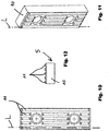
- Figs. 10 through 12 show the second brake block 5. Provided that nothing to the contrary is described below, that which has been said in connection with the first brake block applies analogously to this second brake block.
- this brake block in the region of its left and right outer edges, has respective continuous welding beads extending over its entire length. Between these beads, a plurality of welding beads are provided, preferably 3 or 4 rows of them, which are interrupted in the direction of their longitudinal axis L by an opening, preferably provided with a thread, for fastening this second brake block 5 to the brake caliper 1.
- first and second brake blocks of the indicated type were produced, which were provided with five welding beads completely spaced apart from one another in the direction perpendicular to their longitudinal axes L.
- the welding beads had a width of approximately 4 mm and a contour in the form of a semi-cylindrical shell.
- Two directly adjacent rows were spaced apart from each other by a distance A of about 3 mm.
- the apex of each of the welding beads protruded by approximately 2 mm from the surface of the brake lining support serving as a substrate.
- the welding beads were produced by means of surface-layer welding with the aid of a machine-guided welding laser.
- the raw material from which the welding seams were melted was supplied in powdered form.
- the resulting surface roughness was similar to that of a "porous" surface produced using sand casting; this is not obligatory, but has turned out to be advantageous.
- Their surface roughness when new was preferably Rz > 20, or better still Rz > 50. It is assumed that this surface roughness is responsible for the above-explained wearing-in, i.e. the wear that is pronounced at least in the first braking operation and then levels off significantly.
- corresponding traditional brake blocks were used, which were made of a steel whose surface was uniformly hardened and therefore had a martensitic structure there. They were used to perform catching tests in the same way.
- the brake blocks according to the invention all withstood at least 10 repeated catching operations without exhibiting any significant wear that would have made it necessary to replace the brake blocks.
Landscapes
- Engineering & Computer Science (AREA)
- Mechanical Engineering (AREA)
- General Engineering & Computer Science (AREA)
- Chemical & Material Sciences (AREA)
- Physics & Mathematics (AREA)
- Optics & Photonics (AREA)
- Inorganic Chemistry (AREA)
- Plasma & Fusion (AREA)
- Automation & Control Theory (AREA)
- Structural Engineering (AREA)
- Organic Chemistry (AREA)
- Materials Engineering (AREA)
- Braking Arrangements (AREA)
Claims (18)
- Aufzugsystem mit einem Fahrkorb, Fahrkorb-Führungsschienen, mindestens einer Bremsschiene und einer Bremsvorrichtung und/oder Fangvorrichtung (F), die die Fahrkorbbewegung bestimmt, wenn sie aktiviert ist, und wiederum mindestens einen Bremsklotz (2, 5) aufweist, der mit der Bremsschiene zusammenwirkt, dadurch gekennzeichnet, dass die aktive Fläche dieses Bremsklotzes (2, 5), die in Kontakt mit der Bremsschiene kommt und als der Bremsbelag fungiert, mindestens eine Schweißwulst (11) ist, deren Oberflächenhärte größer ist als die Oberflächenhärte der Bremsschiene.
- Aufzugsystem nach Anspruch 1, dadurch gekennzeichnet, dass der Bremsbelag dieses Bremsklotzes (2, 5) aus mindestens zwei voneinander entfernten Schweißwülsten (11) besteht und idealerweise aus drei bis zehn voneinander entfernten Schweißwülsten (11) besteht.
- Aufzugsystem nach einem der vorangehenden Ansprüche, dadurch gekennzeichnet, dass die Schweißwulst (11) einen halbkreisförmigen, halbelliptischen oder halbovalen Querschnitt senkrecht zu ihrer Längsachse (L) aufweist.
- Aufzugsystem nach Anspruch 1, dadurch gekennzeichnet, dass die Schweißwulst (11) so ausgeführt ist, dass sie zunderfrei ist.
- Aufzugsystem nach einem der vorangehenden Ansprüche, dadurch gekennzeichnet, dass die Oberfläche der mindestens einen Schweißwulst (11) nicht nachgearbeitet ist, insbesondere nicht geschliffen ist und vorzugsweise auch keinerlei anschließender Wärmebehandlung unterzogen wurde.
- Aufzugsystem nach einem der vorangehenden Ansprüche, dadurch gekennzeichnet, dass der Scheitel der Schweißwulst (11) um mehr als das Maß b = 0,5 mm oder noch besser mehr als das Maß b = 1,5 mm im Vergleich zur Oberfläche des direkt an der Bremsschiene orientierten Bremsbelagträgers (10) hervorragt.
- Aufzugsystem nach einem der vorangehenden Ansprüche, dadurch gekennzeichnet, dass die Schweißwulst (11) Karbid, idealerweise Wolframkarbid, enthält.
- Aufzugsystem nach einem der Ansprüche 1 bis 6, dadurch gekennzeichnet, dass die Schweißwulst (11) aus einer nickelbasierten Legierung oder kobaltbasierten Legierung oder in Einzelfällen auch aus einer eisenbasierten Legierung besteht.
- Aufzugsystem nach einem der Ansprüche 1 bis 6, dadurch gekennzeichnet, dass die Schweißwulst (11) aus einer Nickel-, Kobalt-, Chrom- oder Wolframkarbidlegierung oder einem hochlegierten Stahl besteht.
- Aufzugsystem nach dem vorangehenden Anspruch, dadurch gekennzeichnet, dass die Schweißwulst (11) aus einem Material besteht, das mindestens drei verschiedene Legierungsbestandteile aufweist und vorzugsweise aus einer nickelbasierten oder kobaltbasierten Superlegierung besteht, die mit einer Vielzahl - und idealerweise mindestens drei - der folgenden Elemente legiert ist: Co, Ni, Fe, Cr, Mo, W, Re, Ru, Ta, Nb, Al, Ti, Mn, Zr, C und B.
- Aufzugsystem nach einem der vorangehenden Ansprüche, dadurch gekennzeichnet, dass die Schweißwulst (11) mindestens 10 Gew.-%, vorzugsweise mindestens 15 Gew.-%, Cr enthält.
- Aufzugsystem nach einem der vorangehenden Ansprüche, dadurch gekennzeichnet, dass die Schweißwulst (11) mindestens 10 Gew.-%, vorzugsweise mindestens 15 Gew.-%, Ni enthält.
- Aufzugsystem nach einem der vorangehenden Ansprüche, dadurch gekennzeichnet, dass die Schweißwulst (11) mindestens 5 Gew.-%, vorzugsweise mindestens 8 Gew.-%, Mo enthält.
- Aufzugsystem nach einem der vorangehenden Ansprüche, dadurch gekennzeichnet, dass die Schweißwulst (11) mindestens 2 Gew.-% und vorzugsweise höchstens 8 Gew.-%, W enthält.
- Aufzugsystem nach mindestens einem der vorangehenden Ansprüche, dadurch gekennzeichnet, dass die Schweißwulst (11) aus einem Pulver geschmolzen ist.
- Aufzugsystem nach mindestens einem der vorangehenden Ansprüche, dadurch gekennzeichnet, dass der Aufbau der Schweißwulst (11) mittels eines Laser-Auftragschweißens erzeugt wurde.
- Verfahren zum Herstellen eines Aufzug-Bremsklotzes (2, 5), dadurch gekennzeichnet, dass auf einen Bremsbelagträger (10), bestehend aus einem schweißbaren, vorzugsweise niedrig legierten, Stahl zwei Schweißwülste (11) geschweißt werden, die den Bremsbelag bilden, der während des Betriebs in Reibungskontakt mit der Bremsschiene gebracht wird.
- Verfahren nach dem vorangehenden Anspruch, dadurch gekennzeichnet, dass die Schweißwülste (11) mittels eines Laser-Auftragschweißens unter Verwendung eines Metallpulvers erzeugt werden.
Applications Claiming Priority (1)
| Application Number | Priority Date | Filing Date | Title |
|---|---|---|---|
| DE202015102837.7U DE202015102837U1 (de) | 2015-06-01 | 2015-06-01 | Aufzugsbrems- und/oder Fangvorrichtung mit geschweißtem Bremsbelag |
Publications (2)
| Publication Number | Publication Date |
|---|---|
| EP3103752A1 EP3103752A1 (de) | 2016-12-14 |
| EP3103752B1 true EP3103752B1 (de) | 2018-08-01 |
Family
ID=56081387
Family Applications (1)
| Application Number | Title | Priority Date | Filing Date |
|---|---|---|---|
| EP16171665.9A Active EP3103752B1 (de) | 2015-06-01 | 2016-05-27 | Aufzugsbremsmechanismus und/oder -sicherheitsgetriebe mit geschweisstem bremsbelag |
Country Status (6)
| Country | Link |
|---|---|
| US (1) | US10060491B2 (de) |
| EP (1) | EP3103752B1 (de) |
| CN (1) | CN106185527B (de) |
| DE (1) | DE202015102837U1 (de) |
| ES (1) | ES2693112T3 (de) |
| RU (1) | RU2719068C2 (de) |
Families Citing this family (10)
| Publication number | Priority date | Publication date | Assignee | Title |
|---|---|---|---|---|
| GB2544755A (en) * | 2015-11-24 | 2017-05-31 | Stuart Cameron David | Braking element |
| WO2017120235A1 (en) * | 2016-01-04 | 2017-07-13 | Otis Elevator Company | Molybdenum coated elevator safety brakes |
| DE102017200811B3 (de) * | 2017-01-19 | 2018-06-28 | Db Netz Ag | Elektrodynamische Gleisbremse |
| US10214385B2 (en) * | 2017-01-25 | 2019-02-26 | Otis Elevator Company | Elevator brake wedge |
| CN107387605B (zh) * | 2017-06-01 | 2024-01-30 | 凯盛重工有限公司 | 矿用无火花高效制动块 |
| CN109279474B (zh) | 2017-07-21 | 2021-05-07 | 奥的斯电梯公司 | 安全装置,电梯安全系统及电梯系统 |
| CN107553034B (zh) * | 2017-09-11 | 2021-11-09 | 广东精创机械制造有限公司 | 一种电梯安全钳外壳焊接夹具 |
| CN107697767A (zh) * | 2017-11-16 | 2018-02-16 | 苏州文得昌包装设备科技有限公司 | 一种变向对接抑尘提升机 |
| CN110498316A (zh) * | 2019-08-27 | 2019-11-26 | 森赫电梯股份有限公司 | 一种夹轨式无机房电梯救援装置及方法 |
| EP4616083A1 (de) * | 2022-11-07 | 2025-09-17 | Transportation IP Holdings, LLC | Bremsscheiben und verfahren zur herstellung von bremsscheiben |
Family Cites Families (16)
| Publication number | Priority date | Publication date | Assignee | Title |
|---|---|---|---|---|
| SU1255539A1 (ru) * | 1985-02-04 | 1986-09-07 | Центральное Проектно-Конструкторское Бюро По Лифтам Всесоюзного Промышленного Объединения "Союзлифтмаш" | Устройство дл торможени кабины лифта |
| JP2803974B2 (ja) * | 1993-07-30 | 1998-09-24 | 三菱電機株式会社 | エレベーターの非常止め装置 |
| JP3792758B2 (ja) * | 1995-09-06 | 2006-07-05 | 株式会社東芝 | エレベータ非常停止装置用ブレーキシュー、エレベータ非常停止装置および非常停止機能付エレベータ |
| JP3294143B2 (ja) * | 1996-09-10 | 2002-06-24 | 株式会社東芝 | エレベータ非常停止装置用ブレーキシュー、エレベータ用非常停止装置および非常停止機能を有するエレベータ |
| US6371261B1 (en) * | 1997-11-06 | 2002-04-16 | Otis Elevator Company | Molybdenum alloy elevator safety brakes |
| US5964322A (en) * | 1997-11-06 | 1999-10-12 | Otis Elevator Company | Elevator safety brake having a plasma sprayed friction coating |
| US5979615A (en) * | 1997-11-06 | 1999-11-09 | Otis Elevator Company | Carbon--carbon composite elevator safety brakes |
| DE10045881A1 (de) * | 2000-09-14 | 2002-05-08 | Inventio Ag | Sicherheitseinrichtung für einen Aufzug |
| AUPR018700A0 (en) * | 2000-09-18 | 2000-10-12 | Safe Effect Technologies International Limited | A brake shoe and drum brake system incorporating same |
| CA2349795A1 (en) * | 2001-06-07 | 2002-12-07 | Stephen Field | Fenestration sealed frame, insulating glazing panels |
| RU48962U1 (ru) * | 2005-05-24 | 2005-11-10 | Открытое акционерное общество "Одесский машиностроительный завод "Червона Гвардия" | Шахтная лебедка |
| DE102008039672B4 (de) * | 2008-07-24 | 2013-09-19 | Becorit Gmbh | Bremsbelag für eine Scheibenbremse und Bremsbelagsystem |
| CN104271485A (zh) * | 2012-04-30 | 2015-01-07 | 奥的斯电梯公司 | 用于制动器的定制摩擦 |
| BR112015001696A2 (pt) * | 2012-08-02 | 2017-07-04 | Mitsubishi Electric Corp | dispositivo de parada de emergência para elevador |
| WO2014035382A1 (en) * | 2012-08-29 | 2014-03-06 | Otis Elevator Company | Friction brake assembly with an abradable metal foam brake pad |
| ES2710200T3 (es) * | 2013-11-15 | 2019-04-23 | Inventio Ag | Dispositivo de retención para un ascensor |
-
2015
- 2015-06-01 DE DE202015102837.7U patent/DE202015102837U1/de not_active Expired - Lifetime
-
2016
- 2016-05-27 EP EP16171665.9A patent/EP3103752B1/de active Active
- 2016-05-27 ES ES16171665.9T patent/ES2693112T3/es active Active
- 2016-05-31 CN CN201610375182.XA patent/CN106185527B/zh active Active
- 2016-05-31 RU RU2016121403A patent/RU2719068C2/ru active
- 2016-05-31 US US15/169,398 patent/US10060491B2/en active Active
Also Published As
| Publication number | Publication date |
|---|---|
| CN106185527B (zh) | 2020-03-24 |
| RU2016121403A3 (de) | 2019-09-23 |
| CN106185527A (zh) | 2016-12-07 |
| US20160348745A1 (en) | 2016-12-01 |
| US10060491B2 (en) | 2018-08-28 |
| RU2016121403A (ru) | 2017-12-05 |
| RU2719068C2 (ru) | 2020-04-17 |
| ES2693112T3 (es) | 2018-12-07 |
| EP3103752A1 (de) | 2016-12-14 |
| DE202015102837U1 (de) | 2016-09-06 |
Similar Documents
| Publication | Publication Date | Title |
|---|---|---|
| EP3103752A1 (de) | Aufzugsbremsmechanismus und/oder -sicherheitsgetriebe mit geschweisstem bremsbelag | |
| DE10056161A1 (de) | Bremsscheibe und Verfahren zu deren Herstellung | |
| AU2009216933B2 (en) | Rail steel with an excellent combination of wear properties and rolling contact fatigue resistance | |
| KR20140114878A (ko) | 고강도 박강판의 필렛 아크 용접 방법 | |
| US2190611A (en) | Machine for applying wear-resistant plating | |
| US20130188898A1 (en) | Solid bronze bearing with hardness gradient | |
| DE3515198C2 (de) | ||
| JP7410973B2 (ja) | 鉄道車輪の再生用溶接部材およびこれを用いた鉄道車輪の再生方法 | |
| CN104160058A (zh) | 用于生产轨道、轨道交叉口和转辙器的零件的钢以及生产所述零件的方法 | |
| US20240301928A1 (en) | Friction brake, especially for motor vehicles | |
| US20150013518A1 (en) | Composition And Tool For Cutting Metal Sheets | |
| HUE027275T2 (en) | Rail steel, which has an excellent combination of wear properties, resistance to rolling wear and weldability | |
| Hurricks | Overcoming industrial wear | |
| RU2860569C2 (ru) | Фрикционный тормоз, в частности, для транспортных средств с двигателем | |
| CN207029191U (zh) | 一种耐磨铁路货车下芯盘 | |
| JP5632358B2 (ja) | 硬化肉盛用溶接材料とそれによる肉盛溶接層を有する機械部品 | |
| Ramachandran et al. | Comparative evaluation of dry sliding wear behaviour of plasma transferred arc hardfaced surfaces by the pin-on-roller method | |
| US1894819A (en) | Wear resisting ferrous alloy | |
| JPH09194983A (ja) | 耐熱亀裂性に優れたブレーキディスク材 | |
| US2084275A (en) | Weld rod | |
| JPS6024297A (ja) | 継目無鋼管製管用ガイドシユ− | |
| JPH01208415A (ja) | 鋳物の改良処理方法 | |
| KR20000059296A (ko) | 하이 프레스 롤러 크러셔의 롤러 코팅방법 | |
| JPH10212545A (ja) | 疲労強度に優れたブレーキディスク材 | |
| Dadswell et al. | The Manufacture and Properties of Automobile Suspension Springs |
Legal Events
| Date | Code | Title | Description |
|---|---|---|---|
| PUAI | Public reference made under article 153(3) epc to a published international application that has entered the european phase |
Free format text: ORIGINAL CODE: 0009012 |
|
| STAA | Information on the status of an ep patent application or granted ep patent |
Free format text: STATUS: THE APPLICATION HAS BEEN PUBLISHED |
|
| AK | Designated contracting states |
Kind code of ref document: A1 Designated state(s): AL AT BE BG CH CY CZ DE DK EE ES FI FR GB GR HR HU IE IS IT LI LT LU LV MC MK MT NL NO PL PT RO RS SE SI SK SM TR |
|
| AX | Request for extension of the european patent |
Extension state: BA ME |
|
| STAA | Information on the status of an ep patent application or granted ep patent |
Free format text: STATUS: REQUEST FOR EXAMINATION WAS MADE |
|
| 17P | Request for examination filed |
Effective date: 20170609 |
|
| RBV | Designated contracting states (corrected) |
Designated state(s): AL AT BE BG CH CY CZ DE DK EE ES FI FR GB GR HR HU IE IS IT LI LT LU LV MC MK MT NL NO PL PT RO RS SE SI SK SM TR |
|
| GRAP | Despatch of communication of intention to grant a patent |
Free format text: ORIGINAL CODE: EPIDOSNIGR1 |
|
| STAA | Information on the status of an ep patent application or granted ep patent |
Free format text: STATUS: GRANT OF PATENT IS INTENDED |
|
| RIC1 | Information provided on ipc code assigned before grant |
Ipc: B66B 5/18 20060101AFI20180115BHEP Ipc: B66B 5/22 20060101ALN20180115BHEP |
|
| RIC1 | Information provided on ipc code assigned before grant |
Ipc: B66B 5/18 20060101AFI20180131BHEP Ipc: B66B 5/22 20060101ALN20180131BHEP |
|
| INTG | Intention to grant announced |
Effective date: 20180215 |
|
| GRAS | Grant fee paid |
Free format text: ORIGINAL CODE: EPIDOSNIGR3 |
|
| GRAA | (expected) grant |
Free format text: ORIGINAL CODE: 0009210 |
|
| STAA | Information on the status of an ep patent application or granted ep patent |
Free format text: STATUS: THE PATENT HAS BEEN GRANTED |
|
| AK | Designated contracting states |
Kind code of ref document: B1 Designated state(s): AL AT BE BG CH CY CZ DE DK EE ES FI FR GB GR HR HU IE IS IT LI LT LU LV MC MK MT NL NO PL PT RO RS SE SI SK SM TR |
|
| REG | Reference to a national code |
Ref country code: GB Ref legal event code: FG4D |
|
| REG | Reference to a national code |
Ref country code: CH Ref legal event code: EP Ref country code: AT Ref legal event code: REF Ref document number: 1024040 Country of ref document: AT Kind code of ref document: T Effective date: 20180815 |
|
| REG | Reference to a national code |
Ref country code: IE Ref legal event code: FG4D |
|
| REG | Reference to a national code |
Ref country code: DE Ref legal event code: R096 Ref document number: 602016004416 Country of ref document: DE |
|
| REG | Reference to a national code |
Ref country code: NL Ref legal event code: MP Effective date: 20180801 |
|
| REG | Reference to a national code |
Ref country code: ES Ref legal event code: FG2A Ref document number: 2693112 Country of ref document: ES Kind code of ref document: T3 Effective date: 20181207 |
|
| REG | Reference to a national code |
Ref country code: LT Ref legal event code: MG4D |
|
| REG | Reference to a national code |
Ref country code: AT Ref legal event code: MK05 Ref document number: 1024040 Country of ref document: AT Kind code of ref document: T Effective date: 20180801 |
|
| PG25 | Lapsed in a contracting state [announced via postgrant information from national office to epo] |
Ref country code: LT Free format text: LAPSE BECAUSE OF FAILURE TO SUBMIT A TRANSLATION OF THE DESCRIPTION OR TO PAY THE FEE WITHIN THE PRESCRIBED TIME-LIMIT Effective date: 20180801 Ref country code: PL Free format text: LAPSE BECAUSE OF FAILURE TO SUBMIT A TRANSLATION OF THE DESCRIPTION OR TO PAY THE FEE WITHIN THE PRESCRIBED TIME-LIMIT Effective date: 20180801 Ref country code: AT Free format text: LAPSE BECAUSE OF FAILURE TO SUBMIT A TRANSLATION OF THE DESCRIPTION OR TO PAY THE FEE WITHIN THE PRESCRIBED TIME-LIMIT Effective date: 20180801 Ref country code: RS Free format text: LAPSE BECAUSE OF FAILURE TO SUBMIT A TRANSLATION OF THE DESCRIPTION OR TO PAY THE FEE WITHIN THE PRESCRIBED TIME-LIMIT Effective date: 20180801 Ref country code: IS Free format text: LAPSE BECAUSE OF FAILURE TO SUBMIT A TRANSLATION OF THE DESCRIPTION OR TO PAY THE FEE WITHIN THE PRESCRIBED TIME-LIMIT Effective date: 20181201 Ref country code: NO Free format text: LAPSE BECAUSE OF FAILURE TO SUBMIT A TRANSLATION OF THE DESCRIPTION OR TO PAY THE FEE WITHIN THE PRESCRIBED TIME-LIMIT Effective date: 20181101 Ref country code: NL Free format text: LAPSE BECAUSE OF FAILURE TO SUBMIT A TRANSLATION OF THE DESCRIPTION OR TO PAY THE FEE WITHIN THE PRESCRIBED TIME-LIMIT Effective date: 20180801 Ref country code: BG Free format text: LAPSE BECAUSE OF FAILURE TO SUBMIT A TRANSLATION OF THE DESCRIPTION OR TO PAY THE FEE WITHIN THE PRESCRIBED TIME-LIMIT Effective date: 20181101 Ref country code: GR Free format text: LAPSE BECAUSE OF FAILURE TO SUBMIT A TRANSLATION OF THE DESCRIPTION OR TO PAY THE FEE WITHIN THE PRESCRIBED TIME-LIMIT Effective date: 20181102 Ref country code: FI Free format text: LAPSE BECAUSE OF FAILURE TO SUBMIT A TRANSLATION OF THE DESCRIPTION OR TO PAY THE FEE WITHIN THE PRESCRIBED TIME-LIMIT Effective date: 20180801 Ref country code: SE Free format text: LAPSE BECAUSE OF FAILURE TO SUBMIT A TRANSLATION OF THE DESCRIPTION OR TO PAY THE FEE WITHIN THE PRESCRIBED TIME-LIMIT Effective date: 20180801 |
|
| PG25 | Lapsed in a contracting state [announced via postgrant information from national office to epo] |
Ref country code: HR Free format text: LAPSE BECAUSE OF FAILURE TO SUBMIT A TRANSLATION OF THE DESCRIPTION OR TO PAY THE FEE WITHIN THE PRESCRIBED TIME-LIMIT Effective date: 20180801 Ref country code: AL Free format text: LAPSE BECAUSE OF FAILURE TO SUBMIT A TRANSLATION OF THE DESCRIPTION OR TO PAY THE FEE WITHIN THE PRESCRIBED TIME-LIMIT Effective date: 20180801 Ref country code: LV Free format text: LAPSE BECAUSE OF FAILURE TO SUBMIT A TRANSLATION OF THE DESCRIPTION OR TO PAY THE FEE WITHIN THE PRESCRIBED TIME-LIMIT Effective date: 20180801 |
|
| PG25 | Lapsed in a contracting state [announced via postgrant information from national office to epo] |
Ref country code: EE Free format text: LAPSE BECAUSE OF FAILURE TO SUBMIT A TRANSLATION OF THE DESCRIPTION OR TO PAY THE FEE WITHIN THE PRESCRIBED TIME-LIMIT Effective date: 20180801 Ref country code: RO Free format text: LAPSE BECAUSE OF FAILURE TO SUBMIT A TRANSLATION OF THE DESCRIPTION OR TO PAY THE FEE WITHIN THE PRESCRIBED TIME-LIMIT Effective date: 20180801 Ref country code: CZ Free format text: LAPSE BECAUSE OF FAILURE TO SUBMIT A TRANSLATION OF THE DESCRIPTION OR TO PAY THE FEE WITHIN THE PRESCRIBED TIME-LIMIT Effective date: 20180801 |
|
| REG | Reference to a national code |
Ref country code: DE Ref legal event code: R097 Ref document number: 602016004416 Country of ref document: DE |
|
| PG25 | Lapsed in a contracting state [announced via postgrant information from national office to epo] |
Ref country code: SM Free format text: LAPSE BECAUSE OF FAILURE TO SUBMIT A TRANSLATION OF THE DESCRIPTION OR TO PAY THE FEE WITHIN THE PRESCRIBED TIME-LIMIT Effective date: 20180801 Ref country code: DK Free format text: LAPSE BECAUSE OF FAILURE TO SUBMIT A TRANSLATION OF THE DESCRIPTION OR TO PAY THE FEE WITHIN THE PRESCRIBED TIME-LIMIT Effective date: 20180801 Ref country code: SK Free format text: LAPSE BECAUSE OF FAILURE TO SUBMIT A TRANSLATION OF THE DESCRIPTION OR TO PAY THE FEE WITHIN THE PRESCRIBED TIME-LIMIT Effective date: 20180801 |
|
| PLBE | No opposition filed within time limit |
Free format text: ORIGINAL CODE: 0009261 |
|
| STAA | Information on the status of an ep patent application or granted ep patent |
Free format text: STATUS: NO OPPOSITION FILED WITHIN TIME LIMIT |
|
| 26N | No opposition filed |
Effective date: 20190503 |
|
| PG25 | Lapsed in a contracting state [announced via postgrant information from national office to epo] |
Ref country code: SI Free format text: LAPSE BECAUSE OF FAILURE TO SUBMIT A TRANSLATION OF THE DESCRIPTION OR TO PAY THE FEE WITHIN THE PRESCRIBED TIME-LIMIT Effective date: 20180801 |
|
| PG25 | Lapsed in a contracting state [announced via postgrant information from national office to epo] |
Ref country code: MC Free format text: LAPSE BECAUSE OF FAILURE TO SUBMIT A TRANSLATION OF THE DESCRIPTION OR TO PAY THE FEE WITHIN THE PRESCRIBED TIME-LIMIT Effective date: 20180801 |
|
| REG | Reference to a national code |
Ref country code: BE Ref legal event code: MM Effective date: 20190531 |
|
| PG25 | Lapsed in a contracting state [announced via postgrant information from national office to epo] |
Ref country code: LU Free format text: LAPSE BECAUSE OF NON-PAYMENT OF DUE FEES Effective date: 20190527 |
|
| PG25 | Lapsed in a contracting state [announced via postgrant information from national office to epo] |
Ref country code: IE Free format text: LAPSE BECAUSE OF NON-PAYMENT OF DUE FEES Effective date: 20190527 |
|
| PG25 | Lapsed in a contracting state [announced via postgrant information from national office to epo] |
Ref country code: BE Free format text: LAPSE BECAUSE OF NON-PAYMENT OF DUE FEES Effective date: 20190531 |
|
| PG25 | Lapsed in a contracting state [announced via postgrant information from national office to epo] |
Ref country code: PT Free format text: LAPSE BECAUSE OF FAILURE TO SUBMIT A TRANSLATION OF THE DESCRIPTION OR TO PAY THE FEE WITHIN THE PRESCRIBED TIME-LIMIT Effective date: 20181201 |
|
| PG25 | Lapsed in a contracting state [announced via postgrant information from national office to epo] |
Ref country code: CY Free format text: LAPSE BECAUSE OF FAILURE TO SUBMIT A TRANSLATION OF THE DESCRIPTION OR TO PAY THE FEE WITHIN THE PRESCRIBED TIME-LIMIT Effective date: 20180801 |
|
| PG25 | Lapsed in a contracting state [announced via postgrant information from national office to epo] |
Ref country code: HU Free format text: LAPSE BECAUSE OF FAILURE TO SUBMIT A TRANSLATION OF THE DESCRIPTION OR TO PAY THE FEE WITHIN THE PRESCRIBED TIME-LIMIT; INVALID AB INITIO Effective date: 20160527 Ref country code: MT Free format text: LAPSE BECAUSE OF FAILURE TO SUBMIT A TRANSLATION OF THE DESCRIPTION OR TO PAY THE FEE WITHIN THE PRESCRIBED TIME-LIMIT Effective date: 20180801 |
|
| PG25 | Lapsed in a contracting state [announced via postgrant information from national office to epo] |
Ref country code: MK Free format text: LAPSE BECAUSE OF FAILURE TO SUBMIT A TRANSLATION OF THE DESCRIPTION OR TO PAY THE FEE WITHIN THE PRESCRIBED TIME-LIMIT Effective date: 20180801 |
|
| PGFP | Annual fee paid to national office [announced via postgrant information from national office to epo] |
Ref country code: DE Payment date: 20250519 Year of fee payment: 10 |
|
| PGFP | Annual fee paid to national office [announced via postgrant information from national office to epo] |
Ref country code: ES Payment date: 20250616 Year of fee payment: 10 |
|
| PGFP | Annual fee paid to national office [announced via postgrant information from national office to epo] |
Ref country code: IT Payment date: 20250530 Year of fee payment: 10 |
|
| PGFP | Annual fee paid to national office [announced via postgrant information from national office to epo] |
Ref country code: FR Payment date: 20250521 Year of fee payment: 10 |
|
| PGFP | Annual fee paid to national office [announced via postgrant information from national office to epo] |
Ref country code: CH Payment date: 20250601 Year of fee payment: 10 |
|
| PGFP | Annual fee paid to national office [announced via postgrant information from national office to epo] |
Ref country code: TR Payment date: 20250520 Year of fee payment: 10 |
|
| PGFP | Annual fee paid to national office [announced via postgrant information from national office to epo] |
Ref country code: GB Payment date: 20260325 Year of fee payment: 11 |