EP3102964B1 - Proximity sensing systems and methods - Google Patents
Proximity sensing systems and methods Download PDFInfo
- Publication number
- EP3102964B1 EP3102964B1 EP14888815.9A EP14888815A EP3102964B1 EP 3102964 B1 EP3102964 B1 EP 3102964B1 EP 14888815 A EP14888815 A EP 14888815A EP 3102964 B1 EP3102964 B1 EP 3102964B1
- Authority
- EP
- European Patent Office
- Prior art keywords
- ultrasonic
- gain
- signal
- signals
- time
- Prior art date
- Legal status (The legal status is an assumption and is not a legal conclusion. Google has not performed a legal analysis and makes no representation as to the accuracy of the status listed.)
- Active
Links
- 238000000034 method Methods 0.000 title claims description 77
- 230000005540 biological transmission Effects 0.000 claims description 57
- 238000012545 processing Methods 0.000 claims description 27
- 230000002238 attenuated effect Effects 0.000 claims description 22
- 238000001514 detection method Methods 0.000 claims description 15
- 230000004044 response Effects 0.000 claims description 9
- 230000008878 coupling Effects 0.000 claims description 4
- 238000010168 coupling process Methods 0.000 claims description 4
- 238000005859 coupling reaction Methods 0.000 claims description 4
- 238000005259 measurement Methods 0.000 description 61
- 230000008569 process Effects 0.000 description 30
- 239000000523 sample Substances 0.000 description 13
- 238000003199 nucleic acid amplification method Methods 0.000 description 12
- 230000003321 amplification Effects 0.000 description 11
- 238000013459 approach Methods 0.000 description 6
- 230000005236 sound signal Effects 0.000 description 6
- 230000001960 triggered effect Effects 0.000 description 6
- 230000005284 excitation Effects 0.000 description 5
- 230000033001 locomotion Effects 0.000 description 5
- XLYOFNOQVPJJNP-UHFFFAOYSA-N water Substances O XLYOFNOQVPJJNP-UHFFFAOYSA-N 0.000 description 5
- 239000003990 capacitor Substances 0.000 description 4
- 238000004519 manufacturing process Methods 0.000 description 4
- 230000002093 peripheral effect Effects 0.000 description 4
- 238000012360 testing method Methods 0.000 description 4
- 239000011358 absorbing material Substances 0.000 description 3
- 238000004364 calculation method Methods 0.000 description 3
- 230000008859 change Effects 0.000 description 3
- 239000013078 crystal Substances 0.000 description 3
- 238000005265 energy consumption Methods 0.000 description 3
- 238000009434 installation Methods 0.000 description 3
- 239000000463 material Substances 0.000 description 3
- 230000007246 mechanism Effects 0.000 description 3
- 230000009467 reduction Effects 0.000 description 3
- 238000003860 storage Methods 0.000 description 3
- 238000013519 translation Methods 0.000 description 3
- 241001465754 Metazoa Species 0.000 description 2
- XLOMVQKBTHCTTD-UHFFFAOYSA-N Zinc monoxide Chemical compound [Zn]=O XLOMVQKBTHCTTD-UHFFFAOYSA-N 0.000 description 2
- 230000001133 acceleration Effects 0.000 description 2
- 238000004590 computer program Methods 0.000 description 2
- 230000003247 decreasing effect Effects 0.000 description 2
- 238000010586 diagram Methods 0.000 description 2
- 239000010453 quartz Substances 0.000 description 2
- 238000012552 review Methods 0.000 description 2
- VYPSYNLAJGMNEJ-UHFFFAOYSA-N silicon dioxide Inorganic materials O=[Si]=O VYPSYNLAJGMNEJ-UHFFFAOYSA-N 0.000 description 2
- 238000002604 ultrasonography Methods 0.000 description 2
- WKBPZYKAUNRMKP-UHFFFAOYSA-N 1-[2-(2,4-dichlorophenyl)pentyl]1,2,4-triazole Chemical compound C=1C=C(Cl)C=C(Cl)C=1C(CCC)CN1C=NC=N1 WKBPZYKAUNRMKP-UHFFFAOYSA-N 0.000 description 1
- WSMQKESQZFQMFW-UHFFFAOYSA-N 5-methyl-pyrazole-3-carboxylic acid Chemical compound CC1=CC(C(O)=O)=NN1 WSMQKESQZFQMFW-UHFFFAOYSA-N 0.000 description 1
- 241000283690 Bos taurus Species 0.000 description 1
- 241000282465 Canis Species 0.000 description 1
- 241000283073 Equus caballus Species 0.000 description 1
- 241000282324 Felis Species 0.000 description 1
- 241000238631 Hexapoda Species 0.000 description 1
- 239000002033 PVDF binder Substances 0.000 description 1
- 241000283984 Rodentia Species 0.000 description 1
- CZMRCDWAGMRECN-UGDNZRGBSA-N Sucrose Chemical compound O[C@H]1[C@H](O)[C@@H](CO)O[C@@]1(CO)O[C@@H]1[C@H](O)[C@@H](O)[C@H](O)[C@@H](CO)O1 CZMRCDWAGMRECN-UGDNZRGBSA-N 0.000 description 1
- 229930006000 Sucrose Natural products 0.000 description 1
- 238000013473 artificial intelligence Methods 0.000 description 1
- 229910002113 barium titanate Inorganic materials 0.000 description 1
- JRPBQTZRNDNNOP-UHFFFAOYSA-N barium titanate Chemical compound [Ba+2].[Ba+2].[O-][Ti]([O-])([O-])[O-] JRPBQTZRNDNNOP-UHFFFAOYSA-N 0.000 description 1
- 230000004888 barrier function Effects 0.000 description 1
- -1 berlinite Substances 0.000 description 1
- 239000012620 biological material Substances 0.000 description 1
- 210000000988 bone and bone Anatomy 0.000 description 1
- 239000000919 ceramic Substances 0.000 description 1
- 238000004891 communication Methods 0.000 description 1
- 210000003298 dental enamel Anatomy 0.000 description 1
- 210000004268 dentin Anatomy 0.000 description 1
- 238000009795 derivation Methods 0.000 description 1
- 238000013461 design Methods 0.000 description 1
- NKZSPGSOXYXWQA-UHFFFAOYSA-N dioxido(oxo)titanium;lead(2+) Chemical compound [Pb+2].[O-][Ti]([O-])=O NKZSPGSOXYXWQA-UHFFFAOYSA-N 0.000 description 1
- 238000002592 echocardiography Methods 0.000 description 1
- 230000000694 effects Effects 0.000 description 1
- 230000005684 electric field Effects 0.000 description 1
- 238000005516 engineering process Methods 0.000 description 1
- 230000005669 field effect Effects 0.000 description 1
- 230000006870 function Effects 0.000 description 1
- 229910000154 gallium phosphate Inorganic materials 0.000 description 1
- 238000010348 incorporation Methods 0.000 description 1
- 229910052500 inorganic mineral Inorganic materials 0.000 description 1
- HFGPZNIAWCZYJU-UHFFFAOYSA-N lead zirconate titanate Chemical compound [O-2].[O-2].[O-2].[O-2].[O-2].[Ti+4].[Zr+4].[Pb+2] HFGPZNIAWCZYJU-UHFFFAOYSA-N 0.000 description 1
- 229910052451 lead zirconate titanate Inorganic materials 0.000 description 1
- GQYHUHYESMUTHG-UHFFFAOYSA-N lithium niobate Chemical compound [Li+].[O-][Nb](=O)=O GQYHUHYESMUTHG-UHFFFAOYSA-N 0.000 description 1
- 238000000691 measurement method Methods 0.000 description 1
- 239000011707 mineral Substances 0.000 description 1
- 239000002086 nanomaterial Substances 0.000 description 1
- 229920000642 polymer Polymers 0.000 description 1
- 229920002981 polyvinylidene fluoride Polymers 0.000 description 1
- LJCNRYVRMXRIQR-OLXYHTOASA-L potassium sodium L-tartrate Chemical compound [Na+].[K+].[O-]C(=O)[C@H](O)[C@@H](O)C([O-])=O LJCNRYVRMXRIQR-OLXYHTOASA-L 0.000 description 1
- UKDIAJWKFXFVFG-UHFFFAOYSA-N potassium;oxido(dioxo)niobium Chemical compound [K+].[O-][Nb](=O)=O UKDIAJWKFXFVFG-UHFFFAOYSA-N 0.000 description 1
- 230000000644 propagated effect Effects 0.000 description 1
- 239000004065 semiconductor Substances 0.000 description 1
- 235000011006 sodium potassium tartrate Nutrition 0.000 description 1
- XMVONEAAOPAGAO-UHFFFAOYSA-N sodium tungstate Chemical compound [Na+].[Na+].[O-][W]([O-])(=O)=O XMVONEAAOPAGAO-UHFFFAOYSA-N 0.000 description 1
- 239000007787 solid Substances 0.000 description 1
- 238000009987 spinning Methods 0.000 description 1
- 239000000126 substance Substances 0.000 description 1
- 238000006467 substitution reaction Methods 0.000 description 1
- 239000005720 sucrose Substances 0.000 description 1
- 230000001629 suppression Effects 0.000 description 1
- 229920002994 synthetic fiber Polymers 0.000 description 1
- 210000002435 tendon Anatomy 0.000 description 1
- 239000011031 topaz Substances 0.000 description 1
- 229910000218 topaz group Inorganic materials 0.000 description 1
- 229910000231 tourmaline group Inorganic materials 0.000 description 1
- 239000002023 wood Substances 0.000 description 1
- 239000011787 zinc oxide Substances 0.000 description 1
Images


Classifications
-
- G—PHYSICS
- G01—MEASURING; TESTING
- G01B—MEASURING LENGTH, THICKNESS OR SIMILAR LINEAR DIMENSIONS; MEASURING ANGLES; MEASURING AREAS; MEASURING IRREGULARITIES OF SURFACES OR CONTOURS
- G01B17/00—Measuring arrangements characterised by the use of infrasonic, sonic or ultrasonic vibrations
-
- G—PHYSICS
- G01—MEASURING; TESTING
- G01S—RADIO DIRECTION-FINDING; RADIO NAVIGATION; DETERMINING DISTANCE OR VELOCITY BY USE OF RADIO WAVES; LOCATING OR PRESENCE-DETECTING BY USE OF THE REFLECTION OR RERADIATION OF RADIO WAVES; ANALOGOUS ARRANGEMENTS USING OTHER WAVES
- G01S15/00—Systems using the reflection or reradiation of acoustic waves, e.g. sonar systems
- G01S15/02—Systems using the reflection or reradiation of acoustic waves, e.g. sonar systems using reflection of acoustic waves
- G01S15/06—Systems determining the position data of a target
- G01S15/08—Systems for measuring distance only
- G01S15/10—Systems for measuring distance only using transmission of interrupted, pulse-modulated waves
-
- G—PHYSICS
- G01—MEASURING; TESTING
- G01S—RADIO DIRECTION-FINDING; RADIO NAVIGATION; DETERMINING DISTANCE OR VELOCITY BY USE OF RADIO WAVES; LOCATING OR PRESENCE-DETECTING BY USE OF THE REFLECTION OR RERADIATION OF RADIO WAVES; ANALOGOUS ARRANGEMENTS USING OTHER WAVES
- G01S15/00—Systems using the reflection or reradiation of acoustic waves, e.g. sonar systems
- G01S15/88—Sonar systems specially adapted for specific applications
- G01S15/93—Sonar systems specially adapted for specific applications for anti-collision purposes
- G01S15/931—Sonar systems specially adapted for specific applications for anti-collision purposes of land vehicles
-
- G—PHYSICS
- G01—MEASURING; TESTING
- G01S—RADIO DIRECTION-FINDING; RADIO NAVIGATION; DETERMINING DISTANCE OR VELOCITY BY USE OF RADIO WAVES; LOCATING OR PRESENCE-DETECTING BY USE OF THE REFLECTION OR RERADIATION OF RADIO WAVES; ANALOGOUS ARRANGEMENTS USING OTHER WAVES
- G01S15/00—Systems using the reflection or reradiation of acoustic waves, e.g. sonar systems
- G01S15/02—Systems using the reflection or reradiation of acoustic waves, e.g. sonar systems using reflection of acoustic waves
- G01S15/06—Systems determining the position data of a target
- G01S15/08—Systems for measuring distance only
- G01S15/10—Systems for measuring distance only using transmission of interrupted, pulse-modulated waves
- G01S15/101—Particularities of the measurement of distance
-
- G—PHYSICS
- G01—MEASURING; TESTING
- G01S—RADIO DIRECTION-FINDING; RADIO NAVIGATION; DETERMINING DISTANCE OR VELOCITY BY USE OF RADIO WAVES; LOCATING OR PRESENCE-DETECTING BY USE OF THE REFLECTION OR RERADIATION OF RADIO WAVES; ANALOGOUS ARRANGEMENTS USING OTHER WAVES
- G01S15/00—Systems using the reflection or reradiation of acoustic waves, e.g. sonar systems
- G01S15/88—Sonar systems specially adapted for specific applications
- G01S15/93—Sonar systems specially adapted for specific applications for anti-collision purposes
-
- G—PHYSICS
- G01—MEASURING; TESTING
- G01S—RADIO DIRECTION-FINDING; RADIO NAVIGATION; DETERMINING DISTANCE OR VELOCITY BY USE OF RADIO WAVES; LOCATING OR PRESENCE-DETECTING BY USE OF THE REFLECTION OR RERADIATION OF RADIO WAVES; ANALOGOUS ARRANGEMENTS USING OTHER WAVES
- G01S7/00—Details of systems according to groups G01S13/00, G01S15/00, G01S17/00
- G01S7/52—Details of systems according to groups G01S13/00, G01S15/00, G01S17/00 of systems according to group G01S15/00
- G01S7/523—Details of pulse systems
- G01S7/526—Receivers
- G01S7/527—Extracting wanted echo signals
- G01S7/5273—Extracting wanted echo signals using digital techniques
-
- G—PHYSICS
- G01—MEASURING; TESTING
- G01S—RADIO DIRECTION-FINDING; RADIO NAVIGATION; DETERMINING DISTANCE OR VELOCITY BY USE OF RADIO WAVES; LOCATING OR PRESENCE-DETECTING BY USE OF THE REFLECTION OR RERADIATION OF RADIO WAVES; ANALOGOUS ARRANGEMENTS USING OTHER WAVES
- G01S7/00—Details of systems according to groups G01S13/00, G01S15/00, G01S17/00
- G01S7/52—Details of systems according to groups G01S13/00, G01S15/00, G01S17/00 of systems according to group G01S15/00
- G01S7/523—Details of pulse systems
- G01S7/526—Receivers
- G01S7/529—Gain of receiver varied automatically during pulse-recurrence period
-
- G—PHYSICS
- G01—MEASURING; TESTING
- G01S—RADIO DIRECTION-FINDING; RADIO NAVIGATION; DETERMINING DISTANCE OR VELOCITY BY USE OF RADIO WAVES; LOCATING OR PRESENCE-DETECTING BY USE OF THE REFLECTION OR RERADIATION OF RADIO WAVES; ANALOGOUS ARRANGEMENTS USING OTHER WAVES
- G01S7/00—Details of systems according to groups G01S13/00, G01S15/00, G01S17/00
- G01S7/52—Details of systems according to groups G01S13/00, G01S15/00, G01S17/00 of systems according to group G01S15/00
- G01S7/523—Details of pulse systems
- G01S7/524—Transmitters
Definitions
- ultrasonic sensors have been widely used to detect distance to objects.
- ultrasonic sensors are typically configured to generate ultrasonic signals with an ultrasonic transducer and to receive the echo signals reflected back by the objects.
- the distance to an object can be determined based on the propagation speed of sound through the propagation medium such as air.
- Ultrasonic transducers are typically configured to generate ultrasonic signals by high frequency vibrations or resonance caused by an excitation signal. For example, a pulse of electrical energy can cause a piezoelectric transducer to vibrate at a given frequency due to piezoelectricity, thereby generating an ultrasonic sound wave. The echo of the transmitted ultrasonic signal as reflected by an object can then be detected and evaluated to determine a distance to the object.
- the excitation signal e.g., electrical signal
- the vibration of the transducer usually does not stop immediately.
- the transducer typically continues to vibrate for a period of time, albeit in a dampening fashion.
- Such residual vibration or reverberation can be detected by the ultrasonic sensor.
- Reverberation signals can obscure the detection of echo signals.
- the blind zone is the area surrounding the ultrasonic transducer in which echo signals cannot be reliably detected as distinguished from reverberation signals.
- US 5 131 271 A describes an ultrasonic level detector that includes a transducer for generating and receiving bursts of sonic energy at a surface to locate the position of the surface.
- the transducer In response to receiving a burst of energy reflected from the surface, the transducer generates an electrical signal, which is then supplied to a variable gain amplifier. After amplification, the electrical signal is supplied to a comparator and a peak detector. The comparator generates a timing signal upon the electrical signal exceeding a threshold.
- a window generator circuit generates a receive window that controls whether the electrical signal is supplied to the comparator and the magnitude of the threshold on the comparator.
- the peak detector determines the maximum amplitude of the electrical signal, which may be used to vary the amplifier gain and the number of pulses included in an excitation signal which drives the transducer.
- a microprocessor determines the distance between the transducer and the detected surface.
- WO 97/44641 A1 describes an ultrasonic measurement method in an ultrasonic measurement system having an ultrasonic transducer that includes emitting an ultrasonic pulse from the ultrasonic transducer.
- An ultrasonic pulse is received in accordance with a pulse travel time wherein the amplitude of the received ultrasonic pulse varies according to the pulse travel time.
- a first electrical signal is provided representative of the received ultrasonic pulse wherein the amplitude of the first electrical signal varies in accordance with the pulse travel time.
- a second electrical signal is provided in accordance with the first electrical signal wherein the amplitude of the second electrical signal is substantially independent of the pulse travel time.
- variable amplification is applied to the first electrical signal in accordance with the travel time.
- a distance is determined according to the pulse travel time wherein the distance is representative of the distance between the transducer and a material surface.
- the present invention provides methods and systems for reducing or even eliminating the blind zone, thereby decreasing the minimum measuring distance, without increasing the production cost. Unlike the software approach mentioned above, the present invention makes it possible to detect objects located within the blind zone, effectively reduced or eliminating the blind zone. Additionally, the present invention is implemented at the circuit level, thereby avoiding the added cost of production associated with the mechanical approach mentioned above.
- an ultrasonic sensing system comprises an ultrasonic transmitter configured to provide a transmission of ultrasonic signals; an ultrasonic receiver configured to receive ultrasonic signals generated as a result of the transmission including reverberation signals and echo signals; an attenuator circuit connectable to the ultrasonic receiver via a switch, the attenuator circuit operable for attenuating the received ultrasonic signals; and a microcontroller unit (MCU) configured to control the switch to electrically couple the ultrasonic receiver with the attenuator circuit only during a predetermined period of time after the transmission of ultrasonic signals.
- MCU microcontroller unit
- the ultrasonic transmitter is the ultrasonic receiver.
- the predetermined period of time can corresponds to a time period during which the reverberation signals are detectable.
- the predetermined period of time can correspond to a blind zone time period.
- the attenuator circuit is selected based at least in part on a previously-measured amplitude of a reverberation signal or an echo signal.
- the switch includes a single-pole double-throw (SPDT) switch.
- SPDT single-pole double-throw
- the ultrasonic sensing system described herein further comprises a booster configured to increase an energy level associated with the transmission of the ultrasonic signal.
- the booster can be configured to improve the power level of an electric signal that is usable for causing the transmission of ultrasonic signals.
- the ultrasonic sensing system described herein further comprises a gain-adjustable amplifier configured to amplify the echo signals.
- the MCU is further configured to control the gain-adjustable amplifier to vary its gain based at least in part on a value of a timer that corresponds to a measuring distance from the ultrasonic sensing system.
- the MCU may control the gain-adjustable amplifier based on previously-measured data.
- the MCU is further configured to control the switch to electrically couple the ultrasonic receiver with the gain-adjustable amplifier without electrically coupling the attenuator circuit with the gain-adjustable amplifier after the predetermined period of time has elapsed.
- the ultrasonic sensing system described herein further comprises a comparator connected to the gain-adjustable amplifier that is configured to compare an output of the gain-adjustable amplifier with a predetermined threshold value.
- the MCU is further configured to control a gain of the gain-adjustable amplifier based at least in part on an output of the comparator.
- the comparator may or may not be integrated with the MCU.
- the ultrasonic sensing system described herein further comprises an analog-to-digital converter (ADC) connected to the gain-adjustable amplifier that is configured to convert the output of the gain-adjustable amplifier to a digital value.
- ADC analog-to-digital converter
- the gain-adjustable amplifier can be controlled based at least in part on an output of the ADC.
- the ADC may or may not be integrated with the MCU.
- the comparator and the ADC are used in conjunction to determine an occurrence of a peak amplitude.
- a method for ultrasonic sensing can comprise detecting a signal after termination of a transmission of ultrasonic signals, the detected signal can be an echo signal or a reverberation signal; determining whether the detection of the ultrasonic signal occurs within a predetermined period of time from the terminal of the transmission of ultrasonic signals; in response to a determination that the detection of the signal occurs within the predetermined period of time, attenuating the detected signal to sufficiently reduce interference caused by reverberation from the transmission of the ultrasonic signals; and in response to a determination that the detection of the signal occurs after the predetermined period of time has elapsed, processing, without attenuating, the detected signal to determine proximity of an object.
- the predetermined period of time corresponds to a time period during which the reverberation is detectable. In some embodiments, the predetermined period of time corresponds to a blind zone time period.
- the ultrasonic signals transmitted by the transmission are amplified prior to the transmission of the ultrasonic signals, for example, using a booster.
- Attenuating the detected ultrasonic signal is based at least in part on amplitude of one or more previously-measured signal.
- the previously-measured signals can include a reverberation signal, an echo signal, or both.
- processing the detected ultrasonic signal includes determining occurrence of a peak amplitude using a comparator and an analog-to-digital converter (ADC).
- ADC analog-to-digital converter
- Zero, one, or both of the comparator and the ADC can be included in a multi-controller unit (MCU).
- the method described herein can further comprise providing a gain to the detected ultrasonic signal based at least in part on previously-measured data.
- the previously-measured data can correlate a measuring distance and a gain suitable for the measuring distance.
- the method described herein can further comprise providing a gain to the detected ultrasonic signal based at least in part on a timer value.
- an ultrasonic sensing system can comprise an ultrasonic transmitter configured to provide a transmission of ultrasonic signals; an ultrasonic receiver configured to receive ultrasonic signals generated as a result of the transmission including reverberation signals and echo signals; and an attenuator circuit connectable to the ultrasonic receiver, the attenuator circuit operable for eliminating substantially all of the reverberation signals without eliminating the echo signals.
- the ultrasonic transmitter is the ultrasonic receiver.
- the attenuator circuit can be connected to the ultrasonic receiver only during a predetermined period of time.
- the predetermined period of time corresponds to a blind zone time period.
- the attenuator circuit can be selected based at least in part on a previously-measured amplitude of a signal such a reverberation signal or an echo signal.
- the ultrasonic sensing system described herein further comprises a booster configured to increase an energy level associated with the transmission of the ultrasonic signal.
- the booster can be configured to increase a voltage level of an electric signal that is usable for causing the transmission of ultrasonic signals.
- the ultrasonic sensing system described herein further comprises a microcontroller unit (MCU) configured to control a switch to electrically couple the ultrasonic receiver with the attenuator circuit only during a predetermined period of time after the transmission of ultrasound signals.
- the switch can include a single-pole double-throw (SPDT) switch.
- the ultrasonic sensing system described herein further comprises a gain-adjustable amplifier connectable to the ultrasonic receiver via the switch and connected to the attenuator circuit in series, the gain-adjustable amplifier configured to amplify the echo signals.
- the MCU is further configured to control the gain-adjustable amplifier to vary its gain based at least in part on a value of a timer that corresponds to a measuring distance from the ultrasonic sensing system.
- the MCU may control the gain-adjustable amplifier based on previously-measured data.
- the MCU is further configured to control the switch to electrically couple the ultrasonic receiver with the gain-adjustable amplifier without electrically coupling the attenuator circuit with the gain-adjustable amplifier after the predetermined period of time has elapsed.
- the ultrasonic sensing system described herein further comprises a comparator connected to the gain-adjustable amplifier that is configured to compare an output of the gain-adjustable amplifier with a predetermined threshold value.
- the MCU can be further configured to control a gain of the gain-adjustable amplifier based at least in part on an output of the comparator.
- the comparator may or may not be integrated with the MCU.
- the ultrasonic sensing system described herein further comprises an analog-to-digital converter (ADC) connected to the gain-adjustable amplifier that is configured to convert the output of the gain-adjustable amplifier to a digital value.
- ADC analog-to-digital converter
- the gain-adjustable amplifier can be controlled based at least in part on an output of the ADC.
- the ADC may or may not be integrated with the MCU.
- the comparator and the ADC are used in conjunction to determine an occurrence of a peak amplitude.
- a method for ultrasonic sensing comprises detecting an ultrasonic signal after termination of a transmission of ultrasonic signals, wherein the detected ultrasonic signal is an echo signal or a reverberation signal; and attenuating the detected ultrasonic signal, thereby substantially eliminating the reverberation signal without eliminating the echo signal.
- the attenuation of the detected ultrasonic signal is applied only within a predetermined period of time from the transmission of the ultrasonic signals.
- the predetermined period of time can correspond to a blind zone time period.
- the ultrasonic signals transmitted by the transmission are amplified prior to the transmission of the ultrasonic signals, for example, by a booster.
- Attenuating the detected ultrasonic signal is based at least in part on a previously-measured amplitude of a reverberation signal or an echo signal.
- the method described herein further comprises determining occurrence of a peak amplitude using a comparator and an analog-to-digital converter (ADC).
- ADC analog-to-digital converter
- Zero, one or both of the comparator and the ADC can be included in a multi-controller unit (MCU).
- MCU multi-controller unit
- the method described herein further comprises providing a gain to the detected ultrasonic signal based at least in part on previously-measured data.
- the previously-measured data can correlate a measuring distance and a gain suitable for the measuring distance.
- the method described herein further comprises providing a gain to the detected ultrasonic signal based at least in part on a timer value.
- a method for ultrasonic sensing comprises adjusting an amplifier to provide a first gain to received ultrasonic signals based at least in part on previously-measured adjustable gain control (AGC) data; and adjusting the amplifier, at a later point in time, to provide a second gain that is greater than the first gain based at least in part on the previously-measured AGC data.
- AGC adjustable gain control
- the previously-measured AGC data can correlate a measuring distance and a gain suitable for the measuring distance. For instance, the gain can increase, at least in part, as the measuring distance increases.
- the method described herein further comprises adjusting the amplifier to provide increasing gains, over time, until an echo signal is detected or until a predetermined measurement time is reached.
- the received ultrasonic signals are attenuated, prior to being amplified, only if the ultrasonic signals are received during a predetermined period of time.
- the received ultrasonic signals can be attenuated so as to eliminate substantially all of reverberation signals without eliminating echo signals.
- the received ultrasonic signals are attenuated based at least in part on a previously-measured amplitude of a reverberation signal or an echo signal.
- the predetermined period of time can include a blind zone time period.
- the method described herein further comprises determining occurrence of a peak amplitude using a comparator and an analog-to-digital converter (ADC).
- ADC analog-to-digital converter
- Zero, one or both of the comparator and the ADC can be included in a multi-controller unit (MCU).
- MCU multi-controller unit
- an attenuator circuit is introduced to attenuate the received signals during the time period corresponding to the blind zone in order to remove substantially all reverberation signals while preserving substantially all echo signals as reflected from objects.
- the selection and de-selection of the attenuator circuit may be achieved by a controllable switch.
- the amount of attenuation provided by the attenuator circuit may be configurable based on values (e.g., amplitude) of actually measured reverberation signals and echo signals, among other factors.
- a gain-adjustable amplifier may be provided to amplify received signals based on a current measuring distance as indicated by the time that has elapsed since the start of the measurement.
- the amount of gain of the gain-adjustable amplifier may be controlled by a controller based on the measuring distance. The longer the measurement distance, the more attenuated the echo signals tend to be, and hence the more gain is provided by the gain-adjustable amplifier to amplify the echo signals.
- amount of gain is adjusted periodically by the controller based on empirical measurement data.
- the comparator can be used to trigger proximity measurement and the ADC can be used to determine, within a predetermined period of time, a point in time when the relative peak amplitude is received. This point in time can then be used in the calculation of the distance to the object from which the echo signal is reflected. By pinpointing the time of the peak amplitude, the precision and accuracy of the proximity measurement is improved.
- the transmission circuit of the ultrasonic system can include a booster that is configured to increase the electrical power used for the transmission.
- the booster can be implemented by a transformer (e.g., a step-up transformer) configured to increase the voltage level of the electrical signal provided by the controller.
- FIG. 1 illustrates an exemplary ultrasonic sensor 100, in accordance with an embodiment.
- the ultrasonic sensor 100 includes a transmitter 102 and a receiver 104.
- the ultrasonic transmitter is configured to convert electrical signals to sound signals whereas the ultrasonic receiver is configured to convert sound signals to electrical signals.
- the ultrasonic receiver and the ultrasonic transmitter are implemented as separate devices. In other cases, the ultrasonic receiver and the ultrasonic transmitter are implemented by the same device capable of both transmitting and receiving ultrasonic signals.
- the term ultrasonic transducer can refer to an ultrasonic transmitter, ultrasonic receiver, or both.
- the arrow from the ultrasonic transmitter 102 to the ultrasonic receiver 104 illustrates a reverberation 106 that can reach the ultrasonic receiver, e.g., after the transmitter 102 stops actively transmitting ultrasonic signals.
- the ultrasonic transducer (e.g., ultrasonic transmitter, ultrasonic receiver or both) can be constructed using piezoelectric principles.
- the ultrasonic transducer can include a piezoelectric transducer made of natural or synthetic materials that exhibit piezoelectricity such as certain crystals (e.g., quartz, berlinite, sucrose, rochelle salt, topaz, or tourmaline-group minerals), bones, biological materials (e.g., tendon, silk, wood, enamel, dentin, or DNA), synthetic crystals (e.g., gallium orthophosphate or langasite), synthetic ceramics (e.g., lead zirconate titanate, barium titanate, lead titanate, potassium niobate, lithium niobate, lithium tantalate, sodium tungstate, or zinc oxide), polymers (e.g., polyvinylidene fluoride), organic nanostructures, and the like.
- crystals e.g., quartz, berlinite, sucrose, roch
- the ultrasonic transducer can be constructed using non-piezoelectric principles.
- the ultrasonic transducer can comprise magnetostrictive materials that changes size when exposed to magnetic fields.
- the ultrasonic transducer can include a capacitor microphone that uses a thin plate which moves in response to ultrasound waves, causing changes in the electric fields around the plate to convert sound signals to electric currents.
- FIG. 1 also illustrates some exemplary hardware pins provided by an exemplary ultrasonic proximity sensor board.
- the definition of the hardware pins can be defined according to the specific requirement of actual applications. More, less and/or different hardware pins may be provided in various embodiments.
- the hardware pins are defined as follows:
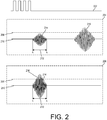
- FIG. 2 illustrates exemplary signals detected by an ultrasonic receiver as a result of an ultrasonic transmission, in accordance with some embodiments.
- an excitation electrical signal or driving pulse 202 causes an ultrasonic transmitter to vibrate and transmit ultrasonic signals.
- the driving pulse 202 is removed at around time t 1 .
- the transmitter does not immediately stop vibrating even though the driving pulse 202 is removed (i.e., voltage level is zero). Instead, the transmitter continues to ring down or residually vibrate, causing residual vibration signal or reverberation signal 214 that can be received by the ultrasonic receiver.
- the signal level as received by the receiver probe is represented by 210.
- the time period t b is thus referred to as the blind zone time period or dead zone time period, indicating a period of time when echo signals cannot be reliable detected as distinctly from the reverberation signals.
- reverberation signals are not suppressed, may be strong enough (e.g., with sufficient amplitude) to trigger the threshold or triggering level 208 of a comparator. Such comparator triggering threshold is often used to determine whether true echo signals have been received.
- the time for the ultrasonic signal to reach the object and travel back to the transducer is less or equal than t b .
- a blind zone refers to an area surrounding the transducer that is covered by the transmission (i.e., a blind zone) within which objects cannot be reliably detected because echoes from the objects tend to be obscured by the presence of reverberation.
- blind zone time period is used to refer to t b , during the ring down of the transducer prevents or obscures the detection of true echo signals.
- shape or size of the blind zone may be determined by the propagation medium, material and/or disposition of the transducer, characteristics of the excitation signal, and other factors. In general, reducing or eliminating blind zone is desirable for increasing the detectable range of proximity sensors, especially for close-range detection.
- FIG. 2 illustrates the receiver signal in two exemplary situations.
- the first scenario 204 an object is located beyond the blind zone of the transducer.
- the echo signal 216 occurs after the blind zone time period, after the occurrence of the reverberation signal 214.
- the echo signal from the object is not obscured by the reverberation signal.
- the echo signal 216 occurs during the same blind zone time period as the reverberation signal 214.
- the reverberation signal 214 can obscure or prevent the detection of the true echo signal 216.
- the reverberation signal 214 is shown as being suppressed or otherwise attenuated (e.g., by a hardware attenuator circuit) to be lower than the triggering value 208 such that the reverberation signal does not falsely trigger the comparator.
- attenuation of the received signals during the blind zone time can be used to effectively reduce or remove the impact of blind zone.
- the true echo signal can also be attenuated if it occurs during the blind zone time period.
- the echo signals are typically stronger than the reverberation signals, especially within close range. Therefore it is possible to attenuate the reverberation signals so as to remove it (e.g., reducing the amplitude to be less than the triggering value of the comparator) while preserving the true echo signal (e.g., leaving the amplitude still greater than triggering value of the comparator).
- the reverberation is typically already weakened by the time it reaches the receiver probe. Other factors contributing to the reduced power of the reverberation signals can include the distance between the receiver and the transmitter, the launch angle of the transmitter and/or other factors.
- the launch angle of the ultrasonic transmitter typically cannot reach 180 degrees.
- Exemplary launch angles can include but not limited to 30, 60, 90, 120, and 150 degrees.
- the echo as reflected by objects located close to the receiver i.e., in the blind zone
- the echo signals are typically stronger than the reverberation signals detected within the blind zone time period. Therefore, it is possible to remove substantially all the reverberation signals while preserving most of the echo signals within the blind zone time period by adjusting the amount of the attenuation.
- the reverberation signal 214 can be substantially or entirely removed (e.g., amplitude of the attenuated reverberation signal 214 is less than the triggering value 208) while substantially preserving the true echo signal 216 (e.g., amplitude of the attenuated echo signal is still greater than the triggering value 208).
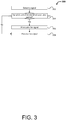
- FIG. 3 illustrates an exemplary process 300 for implementing blind zone reduction, in accordance with an embodiment.
- Some or all aspects of the process 300 may be performed under the control of one or more computers, processors, or control systems configured with executable instructions and may be implemented as code (e.g., executable instructions, one or more computer programs or one or more applications) executing collectively on one or more processors, by hardware or combinations thereof.
- the code may be stored on a computer-readable storage medium, for example, in the form of a computer program comprising a plurality of instructions executable by one or more processors.
- the computer-readable storage medium may be non-transitory.
- the order in which the operations are described is not intended to be construed as a limitation, and any number of the described operations may be combined in any order and/or in parallel to implement the processes.
- aspects of the process 300 can be implemented by components of an ultrasonic sensor system such as illustrated in FIG. 4 .
- the process 300 includes detecting 302 a signal after the termination of a transmission of ultrasonic signals.
- the transmission of the ultrasonic signals can occur in a manner described in FIGs. 1-2 .
- a pulse of electrical energy can be applied to a piezoelectric transmitter, causing it to vibrate or resonate, thereby generating sound waves.
- the transmission is considered terminated.
- the vibration or resonance of the transmitter does not stop immediately. Rather, the transmitter will continue to vibrate, although at dampening amplitudes, for a period of time.
- Such reverberation can be detected by a receiver and converted to an electrical signal (i.e., a reverberation signal).
- the echo may be detected by the receiver and converted to an electrical signal (i.e., an echo signal). From the perspective of the receiver, the detected electrical signal can be either an echo signal or a reverberation signal.
- the process 300 further comprises determining 304 whether the detected signal is detected within a blind zone time period associated with an ultrasonic sensor, such as discussed in FIG. 2 . For example, it can be determined whether the detection of the signal occurs within a predetermined period of time from the terminal of the transmission of ultrasonic signals.
- the predetermined period of time can be the time interval t b discussed above in FIG. 2 that corresponds to the blind zone time period.
- a timer associated with an ultrasonic sensor is started when the transmission of ultrasonic signals terminates or when the transmission starts.
- the current timer value can be compared with a predetermined blind zone time period (e.g., t b ) to determine whether the signal was detected with the blind zone time period.
- the detected signal is attenuated 306 so as to reduce the power (e.g., amplitude) of the signal.
- the detected signal may be an echo signal or reverberation signal that is attenuated during the blind zone time period.
- echo and the detected echo signal
- reverberation tends to be stronger than reverberation (and the detected reverberation signal). This is because the reverberation is typically already weakened by the time it reaches the receiver probe.
- Other factors contributing to the reduced power of the reverberation signals can include the distance between the receiver and the transmitter, the launch angle of the transmitter and/or other factors. For example, the launch angle of the ultrasonic transmitter typically cannot reach 180 degrees.
- Exemplary launch angles can include but not limited to 30, 60, 90, 120, and 150 degrees.
- the echo as reflected by objects located close to the receiver i.e., in the blind zone
- the echo signals are typically stronger than the reverberation signals detected within the blind zone time period. Therefore, it is possible to remove substantially all the reverberation signals while preserving most of the echo signals within the blind zone time period by adjusting the amount of the attenuation.
- the amount of attenuation is selected based on the amplitude of actually measured reverberation signals and/or echo signals. For example, if the maximum amplitude (or other suitable value) based on actually measured reverberation signals is V r and the minimum threshold voltage to trigger proximity measurement is V 0 , (hereinafter the triggering value), then the amount of attenuation may be set to V r - V 0 or greater to ensure that the amplitude of any vibration residual signal is reduced to be at or below the triggering V 0 .
- the attenuation amount can be set to be less than V e - V 0 , where V e is minimum amplitude (or other suitable value) based on actually measured echo signals.
- V e is minimum amplitude (or other suitable value) based on actually measured echo signals.
- the amount of attenuation can be selected to be greater than the difference between the received reverberation signal V r and the triggering value V 0 , but not less than the difference between the received echo signal and the triggering value. However, the amount of attenuation still needs to be less than the minimum echo signal to preserve the echo signals. In other words, ⁇ V > V r ⁇ V 0 ; ⁇ V ⁇ V e ⁇ V 0 ; and ⁇ V ⁇ V e
- the amount of attenuation ⁇ V can be set to be greater than a measured reverberation signal such that V r ⁇ ⁇ V ⁇ V e .
- Vr, Ve, and/or V0 values are determined based on test or calibration measurements. For example, any of the above values may be an average, mean, maximum, minimum, or any other derivation of the measured values.
- the reverberation signals are reduced to zero while the echo signals can be reduced to non-zero values below the triggering value.
- post-attenuation amplification may be necessary to bring the attenuated echo signals above the triggering value in order to trigger proximity measurement processing.
- Amplification can also be necessary to detect echo signals received outside the blind zone time period to compensate for the attenuation caused by the propagation medium.
- the further away an object is from the ultrasonic receiver the more attenuated the echo signal as reflected by the object is.
- greater amplification or gain can be applied as the measurement range increases. Methods for providing dynamically adjusted gain control are discussed in further detail elsewhere in the disclosure.
- the attenuation is switched on and off according to the value of a timer, which may be started at the start or end of the ultrasonic transmission. When the value of the timer is within the blind zone time period, the attenuation is switched on to attenuate the received signals.
- the attenuator When the value of the timer has exceeds the blind zone time period, the attenuation is switched off so that the received signals are no longer attenuated.
- the attenuator may be configured to provide different degrees of attenuation during or beyond the blind zone time period. For example, greater attenuation may be provided during the blind zone time period than outside the blind zone time period.
- processing 308 the signal can include amplifying the signal whether it is attenuated or not. As discussed above, such amplification may be necessary to increase the power of echo signals to a level that is sufficient to trigger the proximity measurement processing. In some embodiments, processing 308 the signal can include calculating the time between the sending of an ultrasonic signal and receiving the echo, thereby measuring the distance to an object. As described in further detail below, methods are provided for improving the precision and accuracy of the proximity measurement.
- FIG. 4 illustrates an exemplary circuit diagram of an ultrasonic sensing system 400, according to an embodiment.
- the ultrasonic sensing system 400 may include more or less components than those shown in FIG. 4 .
- the ultrasonic sensing system 400 can be configured to implement aspects of the techniques discussed herein. For example, the ultrasonic sensing system can be configured to increase the measurement range of the ultrasonic sensing system by reducing or eliminating the blind zone, for example, by applying the time-based attenuation of received signals as discussed in FIG. 3 . Additionally, the ultrasonic sensing system 400 can be configured to maintain or even increase the upper limit of the measurement range of the ultrasonic sensing system by increasing the energy of the ultrasonic transmission and/or by amplifying the received signals. Finally, the ultrasonic sensing system 400 can be configured to provide improved reliability and accuracy of proximity measurement by providing dynamic gain control of the received signals and by using an analog-to-digital converter (ADC) to determine the occurrence of peak amplitude.
- ADC analog-to-digital converter
- the ultrasonic sensing system 400 comprises an ultrasonic transmitter 402 and an ultrasonic receiver 404.
- the ultrasonic transmitter 402 is connected to a transmitter circuit and the ultrasonic receiver 404 is connected to a receiver circuit. Either or both of the transmitter circuit and receiver circuit can be controlled at least in part by a controller 412.
- the ultrasonic transmitter 402 is configured to transmit ultrasonic signals in response to electrical signals and the ultrasonic receiver 404 is configured to convert received sound signals into electrical signals.
- the ultrasonic transmitter 402 and/or an ultrasonic receiver 404 can be implemented by a piezoelectric transducer discussed in connection with FIG. 1 . While the ultrasonic transmitter 402 and the ultrasonic receiver 404 are illustrated as separate devices, in some embodiments, they can be implemented by a single device such as one single piezoelectric transducer.
- boosting of the transmission power is preferable, for example, to overcome the attenuation of the sound signals in the surrounding environment and/or to increase the upper limit of the measurement range.
- sound waves can be absorbed by wave-absorbing materials such as carpet, sponge, and the like. Therefore, when measuring proximity in a carpeted room, the ultrasonic transmission power may need to be increased to compensate for such attenuation.
- ultrasonic transmitter 402 can be connected to a booster circuit 422 (hereinafter booster) that is configured to increase the electrical power used for the transmission.
- the booster 422 can be implemented by a transformer (e.g., a step-up transformer) configured to increase the voltage level of the electrical signal provided by the controller.
- Traditional inverter circuit typically can supply only as much as twice the working voltage to drive the ultrasonic transmitter. Such limited power increase in the transmitted ultrasonic waves may be insufficient to account for the attenuating effect caused wave-absorbing material such as sponge, carpet, and the like in the surrounding environment.
- a booster circuit can boost the transmission voltage by much as six times (or even higher, depends on the hardware design) as the operating voltage. With the significantly improved transmitting power, the reflected wave can be more easily received and used to trigger the receiving circuit even with wave-absorbing materials in the surrounding environment.
- the booster 422 is configured to increase the voltage level of the electrical signal such that the increased voltage level stays within the voltage range associated with the ultrasonic receiver 404.
- additional mechanisms may be required (e.g., when the driving current from the controller 412 is not sufficient) and implemented as part of the transmitter circuit to increase the output current and to maximize the power of the transmission.
- the ultrasonic sensing system 400 provides methods for reducing the impact of blind zone or to realize zero-blind zone (e.g., reducing the size of the blind zone to zero).
- the methods can be similar to that discussed in connection with FIG. 3 .
- reverberation can cause the generation of reverberation signals that can be mistaken for echo signals during the blind zone time period.
- the present invention addresses the above problem at the circuit level by electrically coupling the ultrasonic receiver 404 with an attenuator circuit 408 only during the blind zone time period so as to attenuate or remove substantially all of the reverberation signals while allowing most, if not all, of the echo signals to pass through. Because the attenuation of received signals is implemented at the circuit level, the cost increase is minimal compared with the cost mechanical suppression of reverberation discussed above.
- the ultrasonic receiver 404 is connected to a switch 406 which is controllable by a switch control signal 420 provided by the controller 412.
- the switch control signal 420 can cause the switch 406 to electrically couple the ultrasonic receiver 404 and the attenuator circuit 408 during the blind zone time period so as to attenuate received signals.
- the switch control signal 420 can also cause the switch 406 to electrically decouple the ultrasonic receiver 404 and the attenuator circuit 408 so that the received signals are not attenuated outside the blind zone time period.
- the decision to couple or decouple the attenuator circuit 408 is based on a value of a timer (not shown).
- the timer can be started when the transmitter circuit stops driving the ultrasonic transmitter to transmit ultrasonic signals.
- the switch 406 can remain in a state where the attenuator circuit 408 is selected.
- the switch control signal 420 causes the switch 406 to decouple from the attenuator circuit.
- the switch 406 can include a single-pole, double-throw (SPDT) switch or may include an arbitrary number of poles and/or throws. In other embodiment, switch can include a multiplexer (mux) demultiplexer (demux).
- the switch 406 can also include an electronic switch such as a power metal-oxide-semiconductor field-effect transistor (MOSFET), solid state relay, power transistor, insulated gate bipolar transistor (IGBT) or the like.
- MOSFET power metal-oxide-semiconductor field-effect transistor
- IGBT insulated gate bipolar transistor
- the attenuator circuit 408 can include one or more passive components forming voltage divider networks to reduce the power of an electrical signal.
- the attenuator circuit 408 can include a diode and a capacitor or a resister and a capacitor.
- the components of the attenuator circuit may be arranged in accordance with any arrangement such as the II-type or the T-type.
- the parameters of the attenuator circuit 408 may be configurable to accommodate different circumstances in order to reduce or eliminate reverberation signals without eliminating echo signals.
- the parameters may be adjusted based on actual and/or previous measurement of reverberation signals and/or echo signals. For example, based on the amplitude of the actual reverberation signals and/or echo signals (e.g., as measured by an oscilloscope), parameters of passive components of the attenuator circuit may be selected to achieve the desired amount of attenuation such as discussed in connection with FIG. 3 .
- the capacitance of a capacitor or resistance of a resistor can be selected to increase or decrease the overall amount of attenuation such that it is sufficient to bring the amplitude of reverberation signals below the triggering value and/or to close to zero.
- the characteristics (e.g., amplitude) associated with the actually measured reverberation signals and/or echo signals may be determined by a variety of factors such as parameters or properties of the ultrasonic transmitter/receiver, installation position or method of the ultrasonic transmitter/receiver (e.g., distance between the transmitter probe and the receiver probe, whether mechanical vibration reduction such as padding is in place, etc.), propagation medium, objects in the surrounding environment, and the like. For example, installed using similar methods, different ultrasonic probes may produce different reverberation and/or echo signals. Even the same ultrasonic probes may produce different reverberation and/or echo signals when installed differently.
- the gain value is provided based on the measuring distance.
- a smaller gain is provided for a shorter measuring distance, thereby avoiding over-amplification of the echo from close-range objects.
- the measurement accuracy of ultrasonic sensing systems is improved by the present invention.
- the ultrasonic sensing system 400 includes a gain-adjustable amplifier 410 that is configured to amplify received signals according to an adjustable gain control (AGC) signal 418 provided dynamically by the controller 412.
- AGC adjustable gain control
- the gain-adjustable amplifier 410 can be electrically coupled to the ultrasonic receiver 404 via the switch 406.
- the gain-adjustable amplifier 410 can be connected in series with the attenuator circuit 408 so as to amplify the signals that have been attenuated by the attenuator circuit 408.
- Such post-attenuation amplification may be necessary to bring the attenuated echo signals above the triggering value in order to trigger proximity measurement processing.
- the gain-adjustable amplifier 410 can be used to directly amplify received signals bypassing the attenuator circuit 408 (e.g., via the switch 406). Such amplification of echo signals received outside the blind zone time period can be used to compensate for the attenuation caused by the propagation medium (e.g., air, water) increasing the range and accuracy of the proximity measurement.
- the propagation medium e.g., air, water
- the gain provided by the gain-adjustable amplifier 410 is dynamically adjusted based on the measuring distance. Once the ultrasonic signals are transmitted, the measuring distance of the ultrasonic sensing system increases as transmitted signal is propagated further away. The farther the measuring distance, the more attenuated the echo signal is, due to the attenuation caused by the propagation medium. Hence, more gain generally needs to be provided for the received signals to compensate for the increasing attenuation as the measuring distance increases over time.
- the gain provided by the gain-adjustable amplifier 410 is dynamically adjusted to gradually increase (according to the AGC signal 418) as the measuring distance increases. The adjusted gain may be the same or more than a previously-provided gain.
- the exact attenuation characteristics of the ultrasonic signals may vary depending on the propagation media (e.g., air, water), transmission frequency, transmitter / receiver properties, installation methods, and other factors.
- the AGC signal 418 and hence the gain provided by gain-adjustable amplifier 410 can be provided based at least in part on empirical measurement of the actual gains required to elevate a received echo signal to reach the triggering value or detectable level (e.g., sufficient to trigger an interrupt by a comparator) at varying measuring distances.
- the gain can be automatically adjusted based on the strength of the received signal.
- the gain may be proportional to the strength of the receive signal, for example, in a linear or exponential fashion.
- FIG. 5 illustrates some exemplary AGC gain values (AGC values) associated with various measuring distances or measuring ranges, in accordance with an embodiment.
- AGC values AGC gain values
- the corresponding AGC gain is required to amplify the echo signals received from that measuring distance or range to a detectable level (e.g., exceeding the triggering value defined by a comparator).
- the table on the left side of FIG. 5 shows the measuring ranges ("Range”) in centimeters (cm) in the left column and the corresponding AGC value ("POT AGC Value”) in logarithmic decibel (dB) in the right column.
- the AGC value can be derived based on an input echo signal and an output signal as amplified by a gain-adjustable amplifier and can indicate the degree the input signal is amplified.
- the AGC values may be measured by a potentiometer or other measuring instruments.
- the data shown in FIG.5 illustrates the correlation between AGC value and the measuring distance.
- the chart on the left side of FIG. 5 illustrates the same data.
- the AGC value generally increases as the measuring distance increases. In some cases, the AGC value remains the same for two or more consecutive measuring ranges.
- AGC values may also vary based on the properties of the transmitter / receiver probes, installation methods, propagation medium and other factors.
- a test measurement may be performed to measure and/or calculate the AGC values (such as those illustrated in FIG. 5 ) prior to using the ultrasonic sensing system.
- the echo signals for varying measuring distances can be analyzed (e.g., using an oscillator) to determine the amplitude of the echo signals.
- the measuring distances can be incremented at fixed intervals (e.g., 10 cm).
- the AGC value for the amplifier can be adjusted so as to bring the echo signals to above the triggering value (e.g., the threshold value to trigger a comparator).
- the AGC values derived from such test measurements can be used by the controller of the ultrasonic sensing system to provide gain control signals to the gain-adjustable amplifier so as to attain the desired amount of gain.
- the measuring distances shown in the table and chart of FIG. 5 can be converted to the amount of time that has elapsed since the start of the transmission of ultrasonic signals.
- lookup tables or similar data structures can be created and used for AGC values for particular sensors and/or conditions. Based on such a lookup table, a time-based gain control method can be provided to proximate the distance-based gain control illustrated in FIG. 5 .
- FIG. 6 illustrates an exemplary process 600 for implementing a time-based gain control as described herein, in accordance with an embodiment.
- the process 600 can be used to provide dynamically adjusted gain control to a gain-adjustable amplifier to compensate for varying attenuation of input signals.
- the amount of gain can be adjusted (e.g., incremented or kept the same) as time increases based on the previously measured and/or calculated AGC data.
- aspects of the process 600 can be implemented by the controller 412 of FIG. 4 .
- the process 600 includes waiting 602 for predetermined interrupts.
- predetermined interrupts can indicate the occurrence of predetermined events that require handling, for example, by an interrupt handler or an Interrupt Service Routine (ISR).
- ISR Interrupt Service Routine
- such an interrupt may be triggered by a comparator when the input signal is greater than a predetermined triggering value.
- an interrupt can be triggered when an output of an analog-to-digital converter (ADC) has reached a predetermined threshold value.
- ADC analog-to-digital converter
- the process 600 includes processing 602 the interrupt, for example, by executing the ISR to calculate the proximity to an object. If not, the process 600 includes returning to the waiting block 602.
- the process 600 includes determining 606 whether a predetermined increment of time ⁇ t has elapsed. If so, the AGC gain value is adjusted 608. Otherwise, the process 600 includes returned to the waiting block 602.
- the AGC gain value is adjusted at fixed time intervals.
- the time interval ⁇ t can be configurable to any arbitrary time interval.
- the AGC value can be adjusted at varying time intervals or in response to predetermined events.
- adjusting the AGC gain value can include looking up the empirical AGC data such as illustrated in FIG. 5 or variations thereof to determine a suitable AGC value corresponding to the current measuring distance, or equivalently, the current elapsed time.
- the current timer value it may be determined that the current measuring distance is in the 70-80 cm range (based on the propagation speed of the ultrasonic signal) and the corresponding AGC value is 9 dB according to the table in FIG. 5 .
- the AGC value can be adjusted based on other factors such as an output from a comparator and/or analog-to-digital converter (ADC), various parameters associated with the ultrasonic sensing system, and the like. Based on some or all of these factors, a suitable control signal may be generated by the AGC value and provided to a gain-adjustable amplifier to attain the desirable gain amount.
- process 600 is continued until the time period corresponding to the maximum measuring distance expires. Such maximum measuring distance can configurable.
- the ultrasonic sensing system 400 in FIG. 4 includes a comparator 414 and an ADC 416, each connected to the gain-adjustable amplifier 410.
- the comparator 414 can be configured to compare an input signal from the gain-adjustable amplifier 410 with a predetermined triggering value (e.g., voltage) to provide an indication of whether the input signal is greater than the predetermined triggering value.
- a predetermined triggering value e.g., voltage
- the comparator 414 may be configured to output a "1" if the input signal is greater than the triggering value and a "0" otherwise.
- an output of the comparator can trigger an interrupt such as discussed in FIG. 6 , causing the execution of an ISR.
- the ADC 416 can be configured to convert an analog signal to a digital signal that represents the amplitude (e.g., voltage) of the signal.
- the output of the ADC can be used to trigger an interrupt. For example, such an interrupt can be triggered when the output of the ADC exceeds a predetermined threshold value.
- comparator 414 and/or the ADC 416 can be included as a part of or integrated with the controller 412 such as illustrated in FIG. 4 . Alternatively, the comparator 414 and/or the ADC 416 can be external to the controller 412.
- the comparator 414 and the ADC 416 can be used in conjunction to improve the accuracy and precision of the measurement of the echo signals.
- the comparator 414 can be used to trigger proximity measurement and measurements from the ADC 416 can be used to determine, within a predetermined period of time, a point in time when the relative peak amplitude is received. This point in time can then be used in the calculation of the distance to the object from which the echo signal is received. By pinpointing the time of the peak amplitude, accuracy of the proximity measurement is improved.
- proximity to an object is calculated based on the time interval between the transmission and the receipt of an ultrasonic signal as reflected by the object.
- the transmission of the ultrasonic signal is typically at the time of transmission of the transmitting wave's peak. If the time of the receipt of the ultrasonic signal is set at the time the comparator is triggered by the reflected wave, the measurement is less than accurate because there is a period of time between when a comparator is triggered by the reflected wave (e.g., below the peak amplitude) and when the peak amplitude is reached.
- an ADC it would be relatively easy to detect peak value of the reflected wave and when the peak value is detected. The time when the peak value is detected can then be used to calculate the distance to the object, thereby improving the accuracy of the measurement.
- FIG. 7 illustrates an exemplary process 700 for determining the occurrence of peak amplitude, in accordance with an embodiment.
- the process 700 can be implemented, for example, by software, hardware, or a combination thereof embedded in the controller 412 or elsewhere.
- the process 700 includes determining that the ADC is ready for measurement.
- the ADC is activated for measurement after the comparator is triggered by a received signal.
- an ADC can be configured to take measurement only at certain time intervals. Such time intervals may be configurable by a manufacturer of the ADC, a user of the ADC (e.g., developer, end user, etc.) or the like.
- the current ADC value, ADC curr is obtained 704 using the ADC.
- the ADC value represents the digitalized amplitude value of the input signal to the ADC.
- the current ADC value, ADC curr can be compared with a previously obtained ADC value, ADC old , to determine 706 whether ADC curr > ADC old .
- ADC old is the ADC value in the immediately preceding measurement.
- ADC old is set to 0 at the first ADC measurement and/or after each detection of a peak amplitude (e.g., at or after block 708).
- the process 700 proceeds to block 702 to start the next round of measurement. If, however, the previously obtained ADC value is equal to or greater than the current ADC value, then it means that the peak has been reached.
- the current timer value t peak is recorded 708. In some embodiments, the timer is started at the transmission of the ultrasonic signal. As such, t peak represents the time interval between the transmission and the receiving of the peak of the ultrasonic signal as reflected by an object.
- the process 700 may be used to detect more than one object within the measurement range of an ultrasonic sensor. As such, there can be more than one t peak 's, each associated with a different object. To implement detection of multiple peak amplitude values, the process 700 can include iterating the above process to derive multiple t peak 's as long as the measurement time is not over. Before the start of the iteration of measurement, ADC old may be reset to 0.
- the measurement time typically refers to the time period required to measure a maximum distance from a proximity sensing system implementing the process 700. The measurement time can be determined by the characteristics of the proximity sensing system, the surrounding environment, and/or configurable by a manufacturer, a user, a customer, or the like.
- the process 700 includes determining 710 whether the measurement time is over. If measurement time is over, then the one or more t peak values are returned 712. Otherwise, if the measurement time is not over, the process 700 includes looping back to block 702 to start another iteration of determining when peak amplitude value occurs.
- the comparator 414 and/or ADC 416 can be used to control the gain-adjustable amplifier 410 and/or the switch 406 discussed above.
- the AGC signal 418 and/or the switch control signal 420 may be generated based on an output from the comparator 414 and/or ADC 416.
- the controller 412 can include a microcontroller unit (MCU) on a single integrated circuit board. In some other embodiments, the controller 412 can include a distributed computing system.
- the controller 412 can include a processing unit 424, a memory 426 and input/output peripherals (not shown).
- the processing unit 424 can include one or more processors, such as a programmable processor (e.g., a central processing unit (CPU)).
- the processing unit 424 can be operatively coupled to the memory 426.
- the memory 426 can include one or more units of transitory and/or non-transitory storage media configured to store data, and/or logic, code, and/or program instructions executable by the processing unit 424 for performing one or more routines or functions.
- the memory units may include random access memory (RAM), read-only memory (ROM), erasable programmable read-only memory (PROM), electrically erasable programmable read-only memory (EEPROM), and the like.
- RAM random access memory
- ROM read-only memory
- PROM erasable programmable read-only memory
- EEPROM electrically erasable programmable read-only memory
- the memory units of memory 426 can store data such as the AGC value data or variations thereof discussed in FIG. 5 , input/output data including such as data from the comparator, ADC, timer, sensor, or the like, processing results from the processing unit 424, and the like.
- the memory units of the memory 426 can store operating parameters and/or logic, code and/or program instructions executable by the processing unit 424 to perform any suitable embodiment of the methods described herein.
- the processing unit 424 can be configured to execute instructions causing one or more processors of the processing unit 424 to provide switch control signal 420 to the switch 406 in order to implement the time-based attenuation as discussed in FIG. 3 .
- the processing unit 424 can be configured to execute instructions causing one or more processors of the processing unit 424 to provide AGC control signal to the gain-adjustable amplifier 410 so as to implement the distance-based amplification of received signals such as discussed in connection with FIG. 6 .
- the processing unit 424 can be configured to execute instructions causing one or more processors of the processing unit 424 to determine the occurrence (including the timing) of peak amplitude based on the input from the comparator and the ADC such as discussed above.
- FIG. 4 depicts a single processing unit 424 and a single memory 426, one of skill in the art would appreciate that this is not intended to be limiting, and that the system 400 can include a plurality of processing units and/or memory units of the memory.
- the controller 412 can also include a plurality of input/output peripherals (now shown).
- the controller 412 can include one or more discrete input/out bits, allowing control and/or detection of the logic state of an individual package pin.
- the controller 412 can include one or more serial input/output such as serial ports (e.g., universal asynchronous receiver/transmitters (UARTs)).
- the controller 412 can also include one or more serial communication interfaces such as Inter-Integrated Circuit (I 2 C), Serial Peripheral Interface (SPI) bus, Controller Area Network (CAN) bus, or the like, for system interconnect.
- I 2 C Inter-Integrated Circuit
- SPI Serial Peripheral Interface
- CAN Controller Area Network
- the controller 412 can also include one or more peripherals such as timers, event counters, pulse-width modulation (PWM) generators, clock generator (e.g., an oscillator for quartz timing crystal, resonator or RC circuit), and the like.
- the controller 412 can also include one or more digital-to-analog converters, in-circuit programming and/or debugging support, USB and Ethernet support, and the like.
- the methods and systems described herein can be used by a movable object to provide information with respect the movable object and/or the surrounding environment such as proximity to target objects (e.g., potential obstacles), location of geographical features, location of manmade structures, and the like.
- target objects e.g., potential obstacles
- location of geographical features e.g., location of manmade structures, and the like.
- Such information may be used by the movable object to sense spatial disposition, velocity, and/or acceleration of the movable object (e.g., with respect to up to three degrees of translation and up to three degrees of rotation).
- the information can aid the operations of the movable object including but not limited to path planning, autonomous navigation of the movable object along a predetermined flight path, obstacle avoidance, and the like.
- the movable object may include one or more sensors that may sense the spatial disposition, velocity, and/or acceleration of the movable object (e.g., with respect to up to three degrees of translation and up to three degrees of rotation).
- the one or more sensors can include global positioning system (GPS) sensors, motion sensors, inertial sensors, proximity sensors (e.g., ultrasonic sensor and/or lidar sensor), image sensors, and the like.
- GPS global positioning system
- the proximity sensor can be rotated (e.g., rotated 360°) to obtain distance and position information for a plurality of objects surrounding the movable object.
- the distance and position information for the surrounding objects can be analyzed to determine the spatial disposition and/or motion of the movable object and/or aid in the navigation of the movable object.
- the movable object may also include a controller for controlling the operations of the movable object and/or the components thereof.
- the movable object can also be controlled remotely by a user or controlled locally by an occupant within or on the movable object.
- the movable object is an unmanned movable object, such as an unmanned aerial vehicle (UAV).
- UAV unmanned aerial vehicle
- the movable object can be controlled by a human or an autonomous control system (e.g., a computer control system), or any suitable combination thereof.
- the movable object can be an autonomous or semi-autonomous robot, such as a robot configured with an artificial intelligence.
- aspects of the methods and systems described herein can be implemented by the movable object, a remote control device, or a combination thereof.
- the controller 412 of the proximity sensing system 400 can be implemented by the controller onboard the movable object that is also capable of controlling the operations of the movable object or a controller off board the movable object such as in a remote control device or base station terminal.
- the control signals for the switch and/or the gain-adjustable amplifier in FIG. 4 can be provided by the controller of the movable object and/or the remote control device.
- the proximity measurement and calculation can be performed by the controller of the movable object, a remote control device, a base station or some third-party device.
- the controller of the proximity sensing system may be separate from or integrated with the controller of the movable object.
- the same remote control device may be operable to control the movable object and the proximity sensing system.
- separate remote control devices may be used to control the movable object and the proximity sensing system.
- data provided by the proximity sensing systems described herein may be used alone or in conjunction with data from other sensors or sensing systems onboard and/or off board the movable object such as GPS sensors, motion sensors, inertial sensors, proximity sensors, image sensors, and the like, to provide positional, attitude and/or other state information about the movable object and/or the environment surrounding the movable object.
- the movable object can be configured to move within any suitable environment, such as in air (e.g., a fixed-wing aircraft, a rotary-wing aircraft, or an aircraft having neither fixed wings nor rotary wings), in water (e.g., a ship or a submarine), on ground (e.g., a motor vehicle, such as a car, truck, bus, van, motorcycle; a movable structure or frame such as a stick, fishing pole; or a train), under the ground (e.g., a subway), in space (e.g., a space plane, a satellite, or a probe), or any combination of these environments.
- the movable object can be mounted on a living subject, such as a human or an animal. Suitable animals can include avines, canines, felines, equines, bovines, ovines, porcines, delphines, rodents, or insects.
- the movable object may be capable of moving freely within the environment with respect to six degrees of freedom (e.g., three degrees of freedom in translation and three degrees of freedom in rotation).
- the movement of the movable object can be constrained with respect to one or more degrees of freedom, such as by a predetermined path, track, or orientation.
- the movement can be actuated by any suitable actuation mechanism, such as an engine or a motor.
- the actuation mechanism of the movable object can be powered by any suitable energy source, such as electrical energy, magnetic energy, solar energy, wind energy, gravitational energy, chemical energy, nuclear energy, or any suitable combination thereof.
- the movable object can be a manned or unmanned vehicle.
- Suitable vehicles may include water vehicles, aerial vehicles, space vehicles, or ground vehicles.
- aerial vehicles may be fixed-wing aircraft (e.g., airplane, gliders), rotary-wing aircraft (e.g., helicopters, rotorcraft), aircraft having both fixed wings and rotary wings, or aircraft having neither (e.g., blimps, hot air balloons).
- a vehicle can be self-propelled, such as self-propelled through the air, on or in water, in space, or on or under the ground.
- a self-propelled vehicle can utilize a propulsion system, such as a propulsion system including one or more engines, motors, wheels, axles, magnets, rotors, propellers, blades, nozzles, or any suitable combination thereof.
- the propulsion system can be used to enable the movable object to take off from a surface, land on a surface, maintain its current position and/or orientation (e.g., hover), change orientation, and/or change position.
- the propulsion system can include one or more rotors.
- a rotor can include one or more blades (e.g., one, two, three, four, or more blades) affixed to a central shaft.
- the blades can be disposed symmetrically or asymmetrically about the central shaft.
- the blades can be turned by rotation of the central shaft, which can be driven by a suitable motor or engine.
- the blades can be configured to spin in a clockwise rotation and/or a counterclockwise rotation.
- the rotor can be a horizontal rotor (which may refer to a rotor having a horizontal plane of rotation), a vertically oriented rotor (which may refer to a rotor having a vertical plane of rotation), or a rotor tilted at an intermediate angle between the horizontal and vertical positions.
- horizontally oriented rotors may spin and provide lift to the movable object.
- Vertically oriented rotors may spin and provide thrust to the movable object.
- Rotors oriented an intermediate angle between the horizontal and vertical positions may spin and provide both lift and thrust to the movable object.
- One or more rotors may be used to provide a torque counteracting a torque produced by the spinning of another rotor.
- the movable object can have any suitable size and/or dimensions.
- the movable object may be of a size and/or dimensions to have a human occupant within or on the vehicle.
- the movable object may be of size and/or dimensions smaller than that capable of having a human occupant within or on the vehicle.
- the movable object may be of a size and/or dimensions suitable for being lifted or carried by a human.
- the movable object may be larger than a size and/or dimensions suitable for being lifted or carried by a human.
- the movable object may have a maximum dimension (e.g., length, width, height, diameter, diagonal) of less than or equal to about: 2 cm, 5 cm, 10 cm, 50 cm, 1 m, 2 m, 5 m, or 10 m.
- the maximum dimension may be greater than or equal to about: 2 cm, 5 cm, 10 cm, 50 cm, 1 m, 2 m, 5 m, or 10 m.
- the distance between shafts of opposite rotors of the movable object may be less than or equal to about: 2 cm, 5 cm, 10 cm, 50 cm, 1 m, 2 m, 5 m, or 10 m.
- the distance between shafts of opposite rotors may be greater than or equal to about: 2 cm, 5 cm, 10 cm, 50 cm, 1 m, 2 m, 5 m, or 10 m.
- the movable object may have a volume of less than 100 cm x 100 cm x 100 cm, less than 50 cm x 50 cm x 30 cm, or less than 5 cm x 5 cm x 3 cm.
- the total volume of the movable object may be less than or equal to about: 1 cm 3 , 2 cm 3 , 5 cm 3 , 10 cm 3 , 20 cm 3 , 30 cm 3 , 40 cm 3 , 50 cm 3 , 60 cm 3 , 70 cm 3 , 80 cm 3 , 90 cm 3 , 100 cm 3 , 150 cm 3 , 200 cm 3 , 300 cm 3 , 500 cm 3 , 750 cm 3 , 1000 cm 3 , 5000 cm 3 , 10,000 cm 3 , 100,000 cm 3 , 1 m 3 , or 10 m 3 .
- the total volume of the movable object may be greater than or equal to about: 1 cm 3 , 2 cm 3 , 5 cm 3 , 10 cm 3 , 20 cm 3 , 30 cm 3 , 40 cm 3 , 50 cm 3 , 60 cm 3 , 70 cm 3 , 80 cm 3 , 90 cm 3 , 100 cm 3 , 150 cm 3 , 200 cm 3 , 300 cm 3 , 500 cm 3 , 750 cm 3 , 1000 cm 3 , 5000 cm 3 , 10,000 cm 3 , 100,000 cm 3 , 1 m 3 , or 10 m 3 .
- the movable object may have a footprint (which may refer to the lateral cross-sectional area encompassed by the movable object) less than or equal to about: 32,000 cm 2 , 20,000 cm 2 , 10,000 cm 2 , 1,000 cm 2 , 500 cm 2 , 100 cm 2 , 50 cm 2 , 10 cm 2 , or 5 cm 2 .
- the footprint may be greater than or equal to about: 32,000 cm 2 , 20,000 cm 2 , 10,000 cm 2 , 1,000 cm 2 , 500 cm 2 , 100 cm 2 , 50 cm 2 , 10 cm 2 , or 5 cm 2 .
- the movable object may weigh no more than 1000 kg.
- the weight of the movable object may be less than or equal to about: 1000 kg, 750 kg, 500 kg, 200 kg, 150 kg, 100 kg, 80 kg, 70 kg, 60 kg, 50 kg, 45 kg, 40 kg, 35 kg, 30 kg, 25 kg, 20 kg, 15 kg, 12 kg, 10 kg, 9 kg, 8 kg, 7 kg, 6 kg, 5 kg, 4 kg, 3 kg, 2 kg, 1 kg, 0.5 kg, 0.1 kg, 0.05 kg, or 0.01 kg.
- the weight may be greater than or equal to about: 1000 kg, 750 kg, 500 kg, 200 kg, 150 kg, 100 kg, 80 kg, 70 kg, 60 kg, 50 kg, 45 kg, 40 kg, 35 kg, 30 kg, 25 kg, 20 kg, 15 kg, 12 kg, 10 kg, 9 kg, 8 kg, 7 kg, 6 kg, 5 kg, 4 kg, 3 kg, 2 kg, 1 kg, 0.5 kg, 0.1 kg, 0.05 kg, or 0.01 kg.
- a movable object may be small relative to a load carried by the movable object.
- the load may include a payload and/or a carrier, as described in further detail below.
- a ratio of a movable object weight to a load weight may be greater than, less than, or equal to about 1:1.
- a ratio of a movable object weight to a load weight may be greater than, less than, or equal to about 1:1.
- a ratio of a carrier weight to a load weight may be greater than, less than, or equal to about 1:1.
- the ratio of an movable object weight to a load weight may be less than or equal to: 1:2, 1:3, 1:4, 1:5, 1:10, or even less.
- the ratio of a movable object weight to a load weight can also be greater than or equal to: 2:1, 3:1, 4:1, 5:1, 10:1, or even greater.
- the movable object may have low energy consumption.
- the movable object may use less than about: 5 W/h, 4 W/h, 3 W/h, 2 W/h, 1 W/h, or less.
- a carrier of the movable object may have low energy consumption.
- the carrier may use less than about: 5 W/h, 4 W/h, 3 W/h, 2 W/h, 1 W/h, or less.
- a payload of the movable object may have low energy consumption, such as less than about: 5 W/h, 4 W/h, 3 W/h, 2 W/h, 1 W/h, or less.
Priority Applications (1)
| Application Number | Priority Date | Filing Date | Title |
|---|---|---|---|
| EP20180995.1A EP3736604A1 (en) | 2014-04-11 | 2014-04-11 | Proximity sensing systems and methods |
Applications Claiming Priority (1)
| Application Number | Priority Date | Filing Date | Title |
|---|---|---|---|
| PCT/CN2014/075192 WO2015154308A1 (en) | 2014-04-11 | 2014-04-11 | Proximity sensing systems and methods |
Related Child Applications (2)
| Application Number | Title | Priority Date | Filing Date |
|---|---|---|---|
| EP20180995.1A Division EP3736604A1 (en) | 2014-04-11 | 2014-04-11 | Proximity sensing systems and methods |
| EP20180995.1A Division-Into EP3736604A1 (en) | 2014-04-11 | 2014-04-11 | Proximity sensing systems and methods |
Publications (3)
| Publication Number | Publication Date |
|---|---|
| EP3102964A1 EP3102964A1 (en) | 2016-12-14 |
| EP3102964A4 EP3102964A4 (en) | 2017-03-22 |
| EP3102964B1 true EP3102964B1 (en) | 2020-07-29 |
Family
ID=53732391
Family Applications (2)
| Application Number | Title | Priority Date | Filing Date |
|---|---|---|---|
| EP14888815.9A Active EP3102964B1 (en) | 2014-04-11 | 2014-04-11 | Proximity sensing systems and methods |
| EP20180995.1A Withdrawn EP3736604A1 (en) | 2014-04-11 | 2014-04-11 | Proximity sensing systems and methods |
Family Applications After (1)
| Application Number | Title | Priority Date | Filing Date |
|---|---|---|---|
| EP20180995.1A Withdrawn EP3736604A1 (en) | 2014-04-11 | 2014-04-11 | Proximity sensing systems and methods |
Country Status (5)
| Country | Link |
|---|---|
| US (4) | US9223023B2 (ja) |
| EP (2) | EP3102964B1 (ja) |
| JP (1) | JP6388957B2 (ja) |
| CN (1) | CN104823072B (ja) |
| WO (1) | WO2015154308A1 (ja) |
Families Citing this family (42)
| Publication number | Priority date | Publication date | Assignee | Title |
|---|---|---|---|---|
| CN104823072B (zh) | 2014-04-11 | 2017-07-28 | 深圳市大疆创新科技有限公司 | 距离传感系统及方法 |
| JP6699665B2 (ja) * | 2015-09-08 | 2020-05-27 | ソニー株式会社 | 情報処理装置、情報処理方法及びプログラム |
| US10107902B2 (en) * | 2015-09-29 | 2018-10-23 | Microchip Technology Incorporated | Core independent peripheral based ultrasonic ranging peripheral |
| CN105116406B (zh) * | 2015-09-30 | 2018-11-30 | 长沙开山斧智能科技有限公司 | 一种复合测距仪及其测距方法 |
| US10585178B2 (en) * | 2015-10-21 | 2020-03-10 | Semiconductor Componenents Industries, Llc | Piezo transducer controller and method having adaptively-tuned linear damping |
| US10184797B2 (en) * | 2015-12-18 | 2019-01-22 | Invensense, Inc. | Apparatus and methods for ultrasonic sensor navigation |
| ITUB20161188A1 (it) * | 2016-03-01 | 2017-09-01 | Vodafone Automotive S P A | Determinazione della presenza di un oggetto |
| US10129853B2 (en) | 2016-06-08 | 2018-11-13 | Cognitive Systems Corp. | Operating a motion detection channel in a wireless communication network |
| CN106054199B (zh) * | 2016-06-13 | 2023-12-08 | 零度智控(北京)智能科技有限公司 | 无人机、超声波测距方法及装置 |
| JP6929028B2 (ja) * | 2016-07-29 | 2021-09-01 | キヤノン株式会社 | 測距型センサを用いて人を検知する装置、方法及びプログラム |
| KR101887901B1 (ko) * | 2016-09-08 | 2018-08-13 | 현대오트론 주식회사 | 초음파 센서 구동 장치 및 초음파 센서 구동 방법 |
| CN106526599A (zh) * | 2016-11-21 | 2017-03-22 | 重庆兆洲科技发展有限公司 | 一种超声波测距系统、回波信号接收方法及装置 |
| US10794987B2 (en) | 2016-12-05 | 2020-10-06 | Centrak, Inc. | Hybrid IR-US RTLS system |
| CN108572365B (zh) * | 2017-03-09 | 2020-11-03 | 北京远度互联科技有限公司 | 使用单探头的超声波测距方法、装置及电路 |
| US9989622B1 (en) * | 2017-03-16 | 2018-06-05 | Cognitive Systems Corp. | Controlling radio states for motion detection |
| US10111228B2 (en) | 2017-03-16 | 2018-10-23 | Cognitive Systems Corp. | Selecting wireless communication channels based on signal quality metrics |
| JP6784236B2 (ja) * | 2017-07-10 | 2020-11-11 | 株式会社Soken | 超音波式の物体検出装置 |
| CN109229361A (zh) * | 2017-07-11 | 2019-01-18 | 深圳市道通智能航空技术有限公司 | 电机控制系统及无人机 |
| US10495740B2 (en) | 2017-08-21 | 2019-12-03 | Hamilton Sundstrand Corporation | Short range ultrasonic measurement |
| US10051414B1 (en) | 2017-08-30 | 2018-08-14 | Cognitive Systems Corp. | Detecting motion based on decompositions of channel response variations |
| NO20171742A1 (en) * | 2017-09-15 | 2019-03-18 | Elliptic Laboratories As | User Authentication Control |
| US10109167B1 (en) | 2017-10-20 | 2018-10-23 | Cognitive Systems Corp. | Motion localization in a wireless mesh network based on motion indicator values |
| US10048350B1 (en) | 2017-10-31 | 2018-08-14 | Cognitive Systems Corp. | Motion detection based on groupings of statistical parameters of wireless signals |
| US10228439B1 (en) | 2017-10-31 | 2019-03-12 | Cognitive Systems Corp. | Motion detection based on filtered statistical parameters of wireless signals |
| US10109168B1 (en) | 2017-11-16 | 2018-10-23 | Cognitive Systems Corp. | Motion localization based on channel response characteristics |
| US10108903B1 (en) | 2017-12-08 | 2018-10-23 | Cognitive Systems Corp. | Motion detection based on machine learning of wireless signal properties |
| DE102018201220A1 (de) * | 2018-01-26 | 2019-08-01 | Osram Gmbh | Abstandsdetektionssystem, Verfahren für ein Abstandsdetektionssystem und Fahrzeug |
| WO2020008868A1 (ja) * | 2018-07-06 | 2020-01-09 | 株式会社村田製作所 | 超音波センサ |
| WO2020065701A1 (ja) * | 2018-09-25 | 2020-04-02 | 学校法人 千葉工業大学 | 情報処理装置および移動ロボット |
| CN111198380A (zh) * | 2018-11-19 | 2020-05-26 | 深圳市速腾聚创科技有限公司 | 激光雷达测距系统 |
| EP3884300A4 (en) | 2018-11-19 | 2022-07-27 | Suteng Innovation Technology Co., Ltd. | LIDAR SIGNAL RECEIVING CIRCUITS, LIDAR SIGNAL GAIN CONTROL METHODS, AND LIDARS USING SAME |
| US11137494B2 (en) * | 2018-12-03 | 2021-10-05 | TE Connectivity Services Gmbh | Distance-detection system for determining a time-of-flight measurement and having a reduced dead zone |
| CN109884644A (zh) * | 2019-04-09 | 2019-06-14 | 苏州顺憬志联新材料科技有限公司 | 一种超声波测距芯片 |
| CN111830510B (zh) * | 2019-04-12 | 2024-04-05 | 苏州臻迪智能科技有限公司 | 一种超声波测距方法和超声波检测电路 |
| CN110609161A (zh) * | 2019-09-26 | 2019-12-24 | 江苏理工学院 | 基于stm32的太阳能便携式示波器 |
| EP3862782A1 (en) * | 2020-02-04 | 2021-08-11 | Infineon Technologies AG | Apparatus and method for correcting an input signal |
| CN113495280A (zh) * | 2020-04-07 | 2021-10-12 | 北京万集科技股份有限公司 | 激光雷达测距信息的获取方法、装置、电子设备及存储介质 |
| US11709235B2 (en) | 2020-08-10 | 2023-07-25 | Analog Devices, Inc. | Data reduction techniques in a LIDAR system |
| FR3125330B1 (fr) | 2021-07-19 | 2024-01-12 | Commissariat Energie Atomique | Dispositif d'émission et/ou détection d'ondes acoustiques à fréquence de résonnance variable |
| CN113721229B (zh) * | 2021-11-03 | 2022-02-22 | 汇智机器人科技(深圳)有限公司 | 超声波测距自动增益校准装置、系统及方法 |
| CN114414663B (zh) * | 2022-01-26 | 2023-12-19 | 瀚云科技有限公司 | 一种土壤测量方法、装置、电子设备以及存储介质 |
| WO2024024153A1 (ja) * | 2022-07-29 | 2024-02-01 | 株式会社村田製作所 | 物体検知装置 |
Family Cites Families (39)
| Publication number | Priority date | Publication date | Assignee | Title |
|---|---|---|---|---|
| US4204280A (en) * | 1962-11-21 | 1980-05-20 | The United States Of America As Represented By The Secretary Of The Navy | Underwater signal discrimination system |
| GB1071635A (en) * | 1963-03-02 | 1967-06-07 | Ultra Electronics Ltd | Ultrasonic position sensing equipment |
| US3683324A (en) * | 1970-06-19 | 1972-08-08 | Lowrance Electronics Mfg | Depth meter having improved time varying gain control |
| US4972385A (en) * | 1970-11-16 | 1990-11-20 | The United States Of America, As Represented By The Secretary Of The Navy | Target size classification system |
| CA973632A (en) * | 1973-05-29 | 1975-08-26 | Arthur C. Hudson | Echoencephalograph |
| BE840456A (fr) * | 1975-04-22 | 1976-10-07 | Dispositif de mesure precise des dimensions d'un objet par ultra-sons | |
| US4137777A (en) * | 1977-07-11 | 1979-02-06 | Mediscan Inc. | Ultrasonic body scanner and method |
| US4327738A (en) * | 1979-10-19 | 1982-05-04 | Green Philip S | Endoscopic method & apparatus including ultrasonic B-scan imaging |
| US4325255A (en) * | 1980-04-07 | 1982-04-20 | Energy And Minerals Research Co. | Ultrasonic apparatus and method for measuring the characteristics of materials |
| US4356731A (en) * | 1980-11-03 | 1982-11-02 | General Electric Company | Method and means for generating time gain compensation control signal for use in ultrasonic scanner and the like |
| US4561019A (en) * | 1983-05-16 | 1985-12-24 | Riverside Research Institute | Frequency diversity for image enhancement |
| JPS61241685A (ja) | 1985-04-19 | 1986-10-27 | Hitachi Ltd | 超音波距離計 |
| JPS63256881A (ja) * | 1987-04-14 | 1988-10-24 | Oki Electric Ind Co Ltd | 音響測位装置の送受信装置 |
| JPS6488282A (en) * | 1987-09-30 | 1989-04-03 | Yamatake Honeywell Co Ltd | Ultrasonic switch |
| JP2889661B2 (ja) | 1989-09-21 | 1999-05-10 | 株式会社リコー | 超音波物体認識装置 |
| JP2828689B2 (ja) * | 1989-09-22 | 1998-11-25 | 松下電工株式会社 | 車両周辺監視装置 |
| US4999817A (en) | 1990-02-22 | 1991-03-12 | Halliburton Logging Services, Inc. | Programmable gain control for rotating transducer ultrasonic tools |
| US5131271A (en) * | 1990-04-16 | 1992-07-21 | Magnetrol International, Inc. | Ultrasonic level detector |
| JP2543234B2 (ja) * | 1990-06-29 | 1996-10-16 | 松下電器産業株式会社 | 超音波式物体感知装置 |
| JP2723663B2 (ja) | 1990-09-06 | 1998-03-09 | 日本電気株式会社 | アクティブソーナー装置 |
| US5341345A (en) * | 1993-08-09 | 1994-08-23 | Baker Hughes Incorporated | Ultrasonic stand-off gauge |
| DE19540170C2 (de) * | 1995-10-27 | 1998-01-29 | Endress Hauser Gmbh Co | Verfahren und Anordnung zur Unterdrückung von Festzielechos bei der Abstandsmessung nach dem Impulslaufzeitprinzip |
| US5760309A (en) * | 1996-05-24 | 1998-06-02 | Drexelbrook Engineering Company | Ultrasonic method for material monitoring |
| US5760369A (en) * | 1996-09-20 | 1998-06-02 | Uniek, Inc. | Method of laser cutting paper cards for use in paper sculpture |
| US5917776A (en) | 1996-12-31 | 1999-06-29 | Honeywell Inc. | Means for reducing minimum sensing distance of an ultrasonic proximity sensor |
| JPH1138127A (ja) * | 1997-07-16 | 1999-02-12 | Nec Corp | 残響内目標検出装置及び方法並びに残響内目標検出プログラムを記録した記憶媒体 |
| US6173233B1 (en) * | 1998-12-11 | 2001-01-09 | Eaton Corporation | Back-up proximity sensor for a vehicle employing dual sonic transducers |
| JP3846533B2 (ja) * | 1999-10-04 | 2006-11-15 | 日立工機株式会社 | 超音波センサを用いた距離測定回路の感度調整方法及びその回路を用いた距離測定方法 |
| JP2003248051A (ja) * | 2002-02-26 | 2003-09-05 | Denso Corp | 超音波センサ |
| US6871148B2 (en) * | 2002-07-02 | 2005-03-22 | Battelle Memorial Institute | Ultrasonic system and technique for fluid characterization |
| US7679996B2 (en) * | 2005-06-13 | 2010-03-16 | Robert Ray Gross | Methods and device for ultrasonic range sensing |
| JP2009300233A (ja) * | 2008-06-12 | 2009-12-24 | Toray Eng Co Ltd | 超音波トランスデューサ |
| JP2010078323A (ja) * | 2008-09-23 | 2010-04-08 | Denso Corp | 障害物検知装置 |
| TWI443963B (zh) | 2010-09-17 | 2014-07-01 | Tung Thih Electronic Co Ltd | And a control device capable of suppressing the residual vibration of a piezoelectric element |
| CN102288782A (zh) * | 2011-07-19 | 2011-12-21 | 江苏物联网研究发展中心 | 高精度超声波传感器 |
| DE102012200991A1 (de) * | 2012-01-24 | 2013-07-25 | Robert Bosch Gmbh | Umfelderfassungsvorrichtung und dazugehöriges Verfahren zur Bestimmung der Position und/oder der Bewegung von einem Objekt |
| CN202501858U (zh) * | 2012-02-21 | 2012-10-24 | 同致电子企业股份有限公司 | 超声波传感器装置 |
| CN103235311A (zh) | 2013-03-31 | 2013-08-07 | 四川航达机电技术开发服务中心 | 一种用于汽车倒车的超声波测距系统 |
| CN104823072B (zh) | 2014-04-11 | 2017-07-28 | 深圳市大疆创新科技有限公司 | 距离传感系统及方法 |
-
2014
- 2014-04-11 CN CN201480003033.XA patent/CN104823072B/zh active Active
- 2014-04-11 WO PCT/CN2014/075192 patent/WO2015154308A1/en active Application Filing
- 2014-04-11 EP EP14888815.9A patent/EP3102964B1/en active Active
- 2014-04-11 EP EP20180995.1A patent/EP3736604A1/en not_active Withdrawn
- 2014-04-11 JP JP2016553892A patent/JP6388957B2/ja not_active Expired - Fee Related
- 2014-08-19 US US14/463,578 patent/US9223023B2/en not_active Expired - Fee Related
-
2015
- 2015-11-20 US US14/948,230 patent/US9921057B2/en active Active
-
2018
- 2018-02-02 US US15/887,407 patent/US10852130B2/en active Active
-
2020
- 2020-11-30 US US17/107,098 patent/US20210108915A1/en not_active Abandoned
Non-Patent Citations (1)
| Title |
|---|
| None * |
Also Published As
| Publication number | Publication date |
|---|---|
| US10852130B2 (en) | 2020-12-01 |
| CN104823072A (zh) | 2015-08-05 |
| JP2017508962A (ja) | 2017-03-30 |
| WO2015154308A1 (en) | 2015-10-15 |
| EP3736604A1 (en) | 2020-11-11 |
| JP6388957B2 (ja) | 2018-09-12 |
| US20150292879A1 (en) | 2015-10-15 |
| CN104823072B (zh) | 2017-07-28 |
| EP3102964A1 (en) | 2016-12-14 |
| US9223023B2 (en) | 2015-12-29 |
| US20180172440A1 (en) | 2018-06-21 |
| US20210108915A1 (en) | 2021-04-15 |
| US20160076882A1 (en) | 2016-03-17 |
| EP3102964A4 (en) | 2017-03-22 |
| US9921057B2 (en) | 2018-03-20 |
Similar Documents
| Publication | Publication Date | Title |
|---|---|---|
| US20210108915A1 (en) | Proximity sensing systems and methods | |
| CN207473089U (zh) | 物体检测器 | |
| US8842495B2 (en) | Ultrasonic motion detection | |
| JP6668409B2 (ja) | 超音波感知システムおよび方法 | |
| JP5730300B2 (ja) | 別の無人機から放出されるスプリアスエコーの識別を有する無人機用の超音波テレメトリー法 | |
| CN102139164A (zh) | 一种自动规避障碍物的飞行装置与方法 | |
| US20130286783A1 (en) | Target detection and tracking with multiple ultrasonic transducers | |
| US10935647B2 (en) | Aircraft ground safety for ultrasonic sensors | |
| JP2020522700A5 (ja) | ||
| CN106950983B (zh) | 无人飞行器避障方法及装置 | |
| US10959003B2 (en) | Aircraft ground safety for ultrasonic sensors | |
| EP3735596B1 (en) | Velocity detection in autonomous devices | |
| Stączek | Digital signal processing in ultrasonic based navigation system for mobile robots | |
| Stancovici et al. | Relative positioning system using inter-robot ultrasonic localization turret | |
| JP2010122830A (ja) | 自律移動装置 | |
| JP7265669B1 (ja) | 電波高度計、無人回転翼機 | |
| Liu et al. | Optimization of pMUTs driving waveform based on phase delay to reduce attenuation vibration | |
| CN205809701U (zh) | 无人机 | |
| Ju et al. | RESEARCH AND IMPLEMENTATION OF LONG-DISTANCE ULTRASONIC DETECTION TECHNOLOGY | |
| Generator | Arbitrary Waveform Generator | |
| Wen-cheng et al. | Design of Intelligent Supersonic Rangefinders | |
| JPH07253299A (ja) | 飛しょう体 | |
| CN108873918A (zh) | 定位无人机 |
Legal Events
| Date | Code | Title | Description |
|---|---|---|---|
| PUAI | Public reference made under article 153(3) epc to a published international application that has entered the european phase |
Free format text: ORIGINAL CODE: 0009012 |
|
| STAA | Information on the status of an ep patent application or granted ep patent |
Free format text: STATUS: REQUEST FOR EXAMINATION WAS MADE |
|
| 17P | Request for examination filed |
Effective date: 20160705 |
|
| AK | Designated contracting states |
Kind code of ref document: A1 Designated state(s): AL AT BE BG CH CY CZ DE DK EE ES FI FR GB GR HR HU IE IS IT LI LT LU LV MC MK MT NL NO PL PT RO RS SE SI SK SM TR |
|
| AX | Request for extension of the european patent |
Extension state: BA ME |
|
| REG | Reference to a national code |
Ref country code: DE Ref legal event code: R079 Ref document number: 602014068428 Country of ref document: DE Free format text: PREVIOUS MAIN CLASS: G01S0015000000 Ipc: G01S0015930000 |
|
| A4 | Supplementary search report drawn up and despatched |
Effective date: 20170216 |
|
| RIC1 | Information provided on ipc code assigned before grant |
Ipc: G01S 7/524 20060101ALN20170210BHEP Ipc: G01S 7/527 20060101ALI20170210BHEP Ipc: G01S 15/93 20060101AFI20170210BHEP Ipc: G01S 7/529 20060101ALI20170210BHEP |
|
| DAX | Request for extension of the european patent (deleted) | ||
| GRAP | Despatch of communication of intention to grant a patent |
Free format text: ORIGINAL CODE: EPIDOSNIGR1 |
|
| STAA | Information on the status of an ep patent application or granted ep patent |
Free format text: STATUS: GRANT OF PATENT IS INTENDED |
|
| INTG | Intention to grant announced |
Effective date: 20200302 |
|
| GRAS | Grant fee paid |
Free format text: ORIGINAL CODE: EPIDOSNIGR3 |
|
| GRAA | (expected) grant |
Free format text: ORIGINAL CODE: 0009210 |
|
| STAA | Information on the status of an ep patent application or granted ep patent |
Free format text: STATUS: THE PATENT HAS BEEN GRANTED |
|
| AK | Designated contracting states |
Kind code of ref document: B1 Designated state(s): AL AT BE BG CH CY CZ DE DK EE ES FI FR GB GR HR HU IE IS IT LI LT LU LV MC MK MT NL NO PL PT RO RS SE SI SK SM TR |
|
| REG | Reference to a national code |
Ref country code: CH Ref legal event code: EP |
|
| REG | Reference to a national code |
Ref country code: DE Ref legal event code: R096 Ref document number: 602014068428 Country of ref document: DE |
|
| REG | Reference to a national code |
Ref country code: AT Ref legal event code: REF Ref document number: 1296435 Country of ref document: AT Kind code of ref document: T Effective date: 20200815 |
|
| REG | Reference to a national code |
Ref country code: IE Ref legal event code: FG4D |
|
| REG | Reference to a national code |
Ref country code: LT Ref legal event code: MG4D |
|
| REG | Reference to a national code |
Ref country code: NL Ref legal event code: MP Effective date: 20200729 |
|
| REG | Reference to a national code |
Ref country code: AT Ref legal event code: MK05 Ref document number: 1296435 Country of ref document: AT Kind code of ref document: T Effective date: 20200729 |
|
| PG25 | Lapsed in a contracting state [announced via postgrant information from national office to epo] |
Ref country code: LT Free format text: LAPSE BECAUSE OF FAILURE TO SUBMIT A TRANSLATION OF THE DESCRIPTION OR TO PAY THE FEE WITHIN THE PRESCRIBED TIME-LIMIT Effective date: 20200729 Ref country code: GR Free format text: LAPSE BECAUSE OF FAILURE TO SUBMIT A TRANSLATION OF THE DESCRIPTION OR TO PAY THE FEE WITHIN THE PRESCRIBED TIME-LIMIT Effective date: 20201030 Ref country code: SE Free format text: LAPSE BECAUSE OF FAILURE TO SUBMIT A TRANSLATION OF THE DESCRIPTION OR TO PAY THE FEE WITHIN THE PRESCRIBED TIME-LIMIT Effective date: 20200729 Ref country code: BG Free format text: LAPSE BECAUSE OF FAILURE TO SUBMIT A TRANSLATION OF THE DESCRIPTION OR TO PAY THE FEE WITHIN THE PRESCRIBED TIME-LIMIT Effective date: 20201029 Ref country code: ES Free format text: LAPSE BECAUSE OF FAILURE TO SUBMIT A TRANSLATION OF THE DESCRIPTION OR TO PAY THE FEE WITHIN THE PRESCRIBED TIME-LIMIT Effective date: 20200729 Ref country code: HR Free format text: LAPSE BECAUSE OF FAILURE TO SUBMIT A TRANSLATION OF THE DESCRIPTION OR TO PAY THE FEE WITHIN THE PRESCRIBED TIME-LIMIT Effective date: 20200729 Ref country code: PT Free format text: LAPSE BECAUSE OF FAILURE TO SUBMIT A TRANSLATION OF THE DESCRIPTION OR TO PAY THE FEE WITHIN THE PRESCRIBED TIME-LIMIT Effective date: 20201130 Ref country code: NO Free format text: LAPSE BECAUSE OF FAILURE TO SUBMIT A TRANSLATION OF THE DESCRIPTION OR TO PAY THE FEE WITHIN THE PRESCRIBED TIME-LIMIT Effective date: 20201029 Ref country code: FI Free format text: LAPSE BECAUSE OF FAILURE TO SUBMIT A TRANSLATION OF THE DESCRIPTION OR TO PAY THE FEE WITHIN THE PRESCRIBED TIME-LIMIT Effective date: 20200729 Ref country code: AT Free format text: LAPSE BECAUSE OF FAILURE TO SUBMIT A TRANSLATION OF THE DESCRIPTION OR TO PAY THE FEE WITHIN THE PRESCRIBED TIME-LIMIT Effective date: 20200729 |
|
| PG25 | Lapsed in a contracting state [announced via postgrant information from national office to epo] |
Ref country code: PL Free format text: LAPSE BECAUSE OF FAILURE TO SUBMIT A TRANSLATION OF THE DESCRIPTION OR TO PAY THE FEE WITHIN THE PRESCRIBED TIME-LIMIT Effective date: 20200729 Ref country code: RS Free format text: LAPSE BECAUSE OF FAILURE TO SUBMIT A TRANSLATION OF THE DESCRIPTION OR TO PAY THE FEE WITHIN THE PRESCRIBED TIME-LIMIT Effective date: 20200729 Ref country code: LV Free format text: LAPSE BECAUSE OF FAILURE TO SUBMIT A TRANSLATION OF THE DESCRIPTION OR TO PAY THE FEE WITHIN THE PRESCRIBED TIME-LIMIT Effective date: 20200729 Ref country code: IS Free format text: LAPSE BECAUSE OF FAILURE TO SUBMIT A TRANSLATION OF THE DESCRIPTION OR TO PAY THE FEE WITHIN THE PRESCRIBED TIME-LIMIT Effective date: 20201129 |
|
| PG25 | Lapsed in a contracting state [announced via postgrant information from national office to epo] |
Ref country code: NL Free format text: LAPSE BECAUSE OF FAILURE TO SUBMIT A TRANSLATION OF THE DESCRIPTION OR TO PAY THE FEE WITHIN THE PRESCRIBED TIME-LIMIT Effective date: 20200729 |
|
| PG25 | Lapsed in a contracting state [announced via postgrant information from national office to epo] |
Ref country code: EE Free format text: LAPSE BECAUSE OF FAILURE TO SUBMIT A TRANSLATION OF THE DESCRIPTION OR TO PAY THE FEE WITHIN THE PRESCRIBED TIME-LIMIT Effective date: 20200729 Ref country code: RO Free format text: LAPSE BECAUSE OF FAILURE TO SUBMIT A TRANSLATION OF THE DESCRIPTION OR TO PAY THE FEE WITHIN THE PRESCRIBED TIME-LIMIT Effective date: 20200729 Ref country code: SM Free format text: LAPSE BECAUSE OF FAILURE TO SUBMIT A TRANSLATION OF THE DESCRIPTION OR TO PAY THE FEE WITHIN THE PRESCRIBED TIME-LIMIT Effective date: 20200729 Ref country code: CZ Free format text: LAPSE BECAUSE OF FAILURE TO SUBMIT A TRANSLATION OF THE DESCRIPTION OR TO PAY THE FEE WITHIN THE PRESCRIBED TIME-LIMIT Effective date: 20200729 Ref country code: DK Free format text: LAPSE BECAUSE OF FAILURE TO SUBMIT A TRANSLATION OF THE DESCRIPTION OR TO PAY THE FEE WITHIN THE PRESCRIBED TIME-LIMIT Effective date: 20200729 Ref country code: IT Free format text: LAPSE BECAUSE OF FAILURE TO SUBMIT A TRANSLATION OF THE DESCRIPTION OR TO PAY THE FEE WITHIN THE PRESCRIBED TIME-LIMIT Effective date: 20200729 |
|
| REG | Reference to a national code |
Ref country code: DE Ref legal event code: R097 Ref document number: 602014068428 Country of ref document: DE |
|
| PG25 | Lapsed in a contracting state [announced via postgrant information from national office to epo] |
Ref country code: AL Free format text: LAPSE BECAUSE OF FAILURE TO SUBMIT A TRANSLATION OF THE DESCRIPTION OR TO PAY THE FEE WITHIN THE PRESCRIBED TIME-LIMIT Effective date: 20200729 |
|
| PLBE | No opposition filed within time limit |
Free format text: ORIGINAL CODE: 0009261 |
|
| STAA | Information on the status of an ep patent application or granted ep patent |
Free format text: STATUS: NO OPPOSITION FILED WITHIN TIME LIMIT |
|
| PG25 | Lapsed in a contracting state [announced via postgrant information from national office to epo] |
Ref country code: SK Free format text: LAPSE BECAUSE OF FAILURE TO SUBMIT A TRANSLATION OF THE DESCRIPTION OR TO PAY THE FEE WITHIN THE PRESCRIBED TIME-LIMIT Effective date: 20200729 |
|
| 26N | No opposition filed |
Effective date: 20210430 |
|
| PG25 | Lapsed in a contracting state [announced via postgrant information from national office to epo] |
Ref country code: SI Free format text: LAPSE BECAUSE OF FAILURE TO SUBMIT A TRANSLATION OF THE DESCRIPTION OR TO PAY THE FEE WITHIN THE PRESCRIBED TIME-LIMIT Effective date: 20200729 |
|
| PG25 | Lapsed in a contracting state [announced via postgrant information from national office to epo] |
Ref country code: MC Free format text: LAPSE BECAUSE OF FAILURE TO SUBMIT A TRANSLATION OF THE DESCRIPTION OR TO PAY THE FEE WITHIN THE PRESCRIBED TIME-LIMIT Effective date: 20200729 |
|
| PG25 | Lapsed in a contracting state [announced via postgrant information from national office to epo] |
Ref country code: LU Free format text: LAPSE BECAUSE OF NON-PAYMENT OF DUE FEES Effective date: 20210411 |
|
| REG | Reference to a national code |
Ref country code: BE Ref legal event code: MM Effective date: 20210430 |
|
| PG25 | Lapsed in a contracting state [announced via postgrant information from national office to epo] |
Ref country code: LI Free format text: LAPSE BECAUSE OF NON-PAYMENT OF DUE FEES Effective date: 20210430 Ref country code: CH Free format text: LAPSE BECAUSE OF NON-PAYMENT OF DUE FEES Effective date: 20210430 |
|
| PG25 | Lapsed in a contracting state [announced via postgrant information from national office to epo] |
Ref country code: IE Free format text: LAPSE BECAUSE OF NON-PAYMENT OF DUE FEES Effective date: 20210411 |
|
| PG25 | Lapsed in a contracting state [announced via postgrant information from national office to epo] |
Ref country code: IS Free format text: LAPSE BECAUSE OF FAILURE TO SUBMIT A TRANSLATION OF THE DESCRIPTION OR TO PAY THE FEE WITHIN THE PRESCRIBED TIME-LIMIT Effective date: 20201129 |
|
| PG25 | Lapsed in a contracting state [announced via postgrant information from national office to epo] |
Ref country code: BE Free format text: LAPSE BECAUSE OF NON-PAYMENT OF DUE FEES Effective date: 20210430 |
|
| PGFP | Annual fee paid to national office [announced via postgrant information from national office to epo] |
Ref country code: GB Payment date: 20220425 Year of fee payment: 9 Ref country code: FR Payment date: 20220421 Year of fee payment: 9 Ref country code: DE Payment date: 20220420 Year of fee payment: 9 |
|
| PG25 | Lapsed in a contracting state [announced via postgrant information from national office to epo] |
Ref country code: HU Free format text: LAPSE BECAUSE OF FAILURE TO SUBMIT A TRANSLATION OF THE DESCRIPTION OR TO PAY THE FEE WITHIN THE PRESCRIBED TIME-LIMIT; INVALID AB INITIO Effective date: 20140411 |
|
| P01 | Opt-out of the competence of the unified patent court (upc) registered |
Effective date: 20230523 |
|
| PG25 | Lapsed in a contracting state [announced via postgrant information from national office to epo] |
Ref country code: CY Free format text: LAPSE BECAUSE OF FAILURE TO SUBMIT A TRANSLATION OF THE DESCRIPTION OR TO PAY THE FEE WITHIN THE PRESCRIBED TIME-LIMIT Effective date: 20200729 |
|
| REG | Reference to a national code |
Ref country code: DE Ref legal event code: R119 Ref document number: 602014068428 Country of ref document: DE |
|
| GBPC | Gb: european patent ceased through non-payment of renewal fee |
Effective date: 20230411 |
|
| PG25 | Lapsed in a contracting state [announced via postgrant information from national office to epo] |
Ref country code: GB Free format text: LAPSE BECAUSE OF NON-PAYMENT OF DUE FEES Effective date: 20230411 |
|
| PG25 | Lapsed in a contracting state [announced via postgrant information from national office to epo] |
Ref country code: GB Free format text: LAPSE BECAUSE OF NON-PAYMENT OF DUE FEES Effective date: 20230411 Ref country code: FR Free format text: LAPSE BECAUSE OF NON-PAYMENT OF DUE FEES Effective date: 20230430 Ref country code: DE Free format text: LAPSE BECAUSE OF NON-PAYMENT OF DUE FEES Effective date: 20231103 |