EP3101246B1 - Carter de catalyseur, conduit d'échappement et moteur - Google Patents
Carter de catalyseur, conduit d'échappement et moteur Download PDFInfo
- Publication number
- EP3101246B1 EP3101246B1 EP15742981.2A EP15742981A EP3101246B1 EP 3101246 B1 EP3101246 B1 EP 3101246B1 EP 15742981 A EP15742981 A EP 15742981A EP 3101246 B1 EP3101246 B1 EP 3101246B1
- Authority
- EP
- European Patent Office
- Prior art keywords
- storage case
- oxidation catalysts
- exhaust
- catalyst storage
- cylinder
- Prior art date
- Legal status (The legal status is an assumption and is not a legal conclusion. Google has not performed a legal analysis and makes no representation as to the accuracy of the status listed.)
- Active
Links
- 239000003054 catalyst Substances 0.000 title claims description 140
- 230000003647 oxidation Effects 0.000 claims description 78
- 238000007254 oxidation reaction Methods 0.000 claims description 78
- 239000007789 gas Substances 0.000 description 26
- 238000002485 combustion reaction Methods 0.000 description 14
- MWUXSHHQAYIFBG-UHFFFAOYSA-N Nitric oxide Chemical compound O=[N] MWUXSHHQAYIFBG-UHFFFAOYSA-N 0.000 description 10
- 238000005192 partition Methods 0.000 description 8
- 229910052751 metal Inorganic materials 0.000 description 6
- 239000002184 metal Substances 0.000 description 6
- 239000002699 waste material Substances 0.000 description 6
- JCXJVPUVTGWSNB-UHFFFAOYSA-N nitrogen dioxide Inorganic materials O=[N]=O JCXJVPUVTGWSNB-UHFFFAOYSA-N 0.000 description 5
- 239000000446 fuel Substances 0.000 description 4
- 239000002828 fuel tank Substances 0.000 description 4
- BASFCYQUMIYNBI-UHFFFAOYSA-N platinum Chemical compound [Pt] BASFCYQUMIYNBI-UHFFFAOYSA-N 0.000 description 4
- 238000003466 welding Methods 0.000 description 4
- 238000002347 injection Methods 0.000 description 3
- 239000007924 injection Substances 0.000 description 3
- 239000004215 Carbon black (E152) Substances 0.000 description 2
- CURLTUGMZLYLDI-UHFFFAOYSA-N Carbon dioxide Chemical compound O=C=O CURLTUGMZLYLDI-UHFFFAOYSA-N 0.000 description 2
- UGFAIRIUMAVXCW-UHFFFAOYSA-N Carbon monoxide Chemical compound [O+]#[C-] UGFAIRIUMAVXCW-UHFFFAOYSA-N 0.000 description 2
- KDLHZDBZIXYQEI-UHFFFAOYSA-N Palladium Chemical compound [Pd] KDLHZDBZIXYQEI-UHFFFAOYSA-N 0.000 description 2
- 229910002091 carbon monoxide Inorganic materials 0.000 description 2
- 230000003197 catalytic effect Effects 0.000 description 2
- 229910052878 cordierite Inorganic materials 0.000 description 2
- 239000002283 diesel fuel Substances 0.000 description 2
- JSKIRARMQDRGJZ-UHFFFAOYSA-N dimagnesium dioxido-bis[(1-oxido-3-oxo-2,4,6,8,9-pentaoxa-1,3-disila-5,7-dialuminabicyclo[3.3.1]nonan-7-yl)oxy]silane Chemical compound [Mg++].[Mg++].[O-][Si]([O-])(O[Al]1O[Al]2O[Si](=O)O[Si]([O-])(O1)O2)O[Al]1O[Al]2O[Si](=O)O[Si]([O-])(O1)O2 JSKIRARMQDRGJZ-UHFFFAOYSA-N 0.000 description 2
- 239000012530 fluid Substances 0.000 description 2
- 229930195733 hydrocarbon Natural products 0.000 description 2
- 150000002430 hydrocarbons Chemical class 0.000 description 2
- 230000002452 interceptive effect Effects 0.000 description 2
- 230000001590 oxidative effect Effects 0.000 description 2
- 229910052697 platinum Inorganic materials 0.000 description 2
- 238000011144 upstream manufacturing Methods 0.000 description 2
- MGWGWNFMUOTEHG-UHFFFAOYSA-N 4-(3,5-dimethylphenyl)-1,3-thiazol-2-amine Chemical compound CC1=CC(C)=CC(C=2N=C(N)SC=2)=C1 MGWGWNFMUOTEHG-UHFFFAOYSA-N 0.000 description 1
- 229910002092 carbon dioxide Inorganic materials 0.000 description 1
- 239000001569 carbon dioxide Substances 0.000 description 1
- 239000000969 carrier Substances 0.000 description 1
- 239000000919 ceramic Substances 0.000 description 1
- 238000001816 cooling Methods 0.000 description 1
- 230000007423 decrease Effects 0.000 description 1
- 230000000694 effects Effects 0.000 description 1
- 229910052741 iridium Inorganic materials 0.000 description 1
- GKOZUEZYRPOHIO-UHFFFAOYSA-N iridium atom Chemical compound [Ir] GKOZUEZYRPOHIO-UHFFFAOYSA-N 0.000 description 1
- 239000000463 material Substances 0.000 description 1
- 229910052763 palladium Inorganic materials 0.000 description 1
- 239000013618 particulate matter Substances 0.000 description 1
- 230000000149 penetrating effect Effects 0.000 description 1
- 229910052703 rhodium Inorganic materials 0.000 description 1
- 239000010948 rhodium Substances 0.000 description 1
- MHOVAHRLVXNVSD-UHFFFAOYSA-N rhodium atom Chemical compound [Rh] MHOVAHRLVXNVSD-UHFFFAOYSA-N 0.000 description 1
- HBMJWWWQQXIZIP-UHFFFAOYSA-N silicon carbide Chemical compound [Si+]#[C-] HBMJWWWQQXIZIP-UHFFFAOYSA-N 0.000 description 1
- 229910010271 silicon carbide Inorganic materials 0.000 description 1
- 239000000243 solution Substances 0.000 description 1
- 229910001220 stainless steel Inorganic materials 0.000 description 1
- 239000010935 stainless steel Substances 0.000 description 1
- XLYOFNOQVPJJNP-UHFFFAOYSA-N water Substances O XLYOFNOQVPJJNP-UHFFFAOYSA-N 0.000 description 1
- 229910001868 water Inorganic materials 0.000 description 1
Images


Classifications
-
- F—MECHANICAL ENGINEERING; LIGHTING; HEATING; WEAPONS; BLASTING
- F01—MACHINES OR ENGINES IN GENERAL; ENGINE PLANTS IN GENERAL; STEAM ENGINES
- F01N—GAS-FLOW SILENCERS OR EXHAUST APPARATUS FOR MACHINES OR ENGINES IN GENERAL; GAS-FLOW SILENCERS OR EXHAUST APPARATUS FOR INTERNAL COMBUSTION ENGINES
- F01N3/00—Exhaust or silencing apparatus having means for purifying, rendering innocuous, or otherwise treating exhaust
- F01N3/08—Exhaust or silencing apparatus having means for purifying, rendering innocuous, or otherwise treating exhaust for rendering innocuous
- F01N3/10—Exhaust or silencing apparatus having means for purifying, rendering innocuous, or otherwise treating exhaust for rendering innocuous by thermal or catalytic conversion of noxious components of exhaust
- F01N3/24—Exhaust or silencing apparatus having means for purifying, rendering innocuous, or otherwise treating exhaust for rendering innocuous by thermal or catalytic conversion of noxious components of exhaust characterised by constructional aspects of converting apparatus
- F01N3/28—Construction of catalytic reactors
- F01N3/2882—Catalytic reactors combined or associated with other devices, e.g. exhaust silencers or other exhaust purification devices
-
- F—MECHANICAL ENGINEERING; LIGHTING; HEATING; WEAPONS; BLASTING
- F01—MACHINES OR ENGINES IN GENERAL; ENGINE PLANTS IN GENERAL; STEAM ENGINES
- F01N—GAS-FLOW SILENCERS OR EXHAUST APPARATUS FOR MACHINES OR ENGINES IN GENERAL; GAS-FLOW SILENCERS OR EXHAUST APPARATUS FOR INTERNAL COMBUSTION ENGINES
- F01N13/00—Exhaust or silencing apparatus characterised by constructional features ; Exhaust or silencing apparatus, or parts thereof, having pertinent characteristics not provided for in, or of interest apart from, groups F01N1/00 - F01N5/00, F01N9/00, F01N11/00
- F01N13/011—Exhaust or silencing apparatus characterised by constructional features ; Exhaust or silencing apparatus, or parts thereof, having pertinent characteristics not provided for in, or of interest apart from, groups F01N1/00 - F01N5/00, F01N9/00, F01N11/00 having two or more purifying devices arranged in parallel
- F01N13/017—Exhaust or silencing apparatus characterised by constructional features ; Exhaust or silencing apparatus, or parts thereof, having pertinent characteristics not provided for in, or of interest apart from, groups F01N1/00 - F01N5/00, F01N9/00, F01N11/00 having two or more purifying devices arranged in parallel the purifying devices are arranged in a single housing
-
- F—MECHANICAL ENGINEERING; LIGHTING; HEATING; WEAPONS; BLASTING
- F01—MACHINES OR ENGINES IN GENERAL; ENGINE PLANTS IN GENERAL; STEAM ENGINES
- F01N—GAS-FLOW SILENCERS OR EXHAUST APPARATUS FOR MACHINES OR ENGINES IN GENERAL; GAS-FLOW SILENCERS OR EXHAUST APPARATUS FOR INTERNAL COMBUSTION ENGINES
- F01N3/00—Exhaust or silencing apparatus having means for purifying, rendering innocuous, or otherwise treating exhaust
- F01N3/08—Exhaust or silencing apparatus having means for purifying, rendering innocuous, or otherwise treating exhaust for rendering innocuous
- F01N3/10—Exhaust or silencing apparatus having means for purifying, rendering innocuous, or otherwise treating exhaust for rendering innocuous by thermal or catalytic conversion of noxious components of exhaust
- F01N3/103—Oxidation catalysts for HC and CO only
-
- F—MECHANICAL ENGINEERING; LIGHTING; HEATING; WEAPONS; BLASTING
- F01—MACHINES OR ENGINES IN GENERAL; ENGINE PLANTS IN GENERAL; STEAM ENGINES
- F01N—GAS-FLOW SILENCERS OR EXHAUST APPARATUS FOR MACHINES OR ENGINES IN GENERAL; GAS-FLOW SILENCERS OR EXHAUST APPARATUS FOR INTERNAL COMBUSTION ENGINES
- F01N3/00—Exhaust or silencing apparatus having means for purifying, rendering innocuous, or otherwise treating exhaust
- F01N3/08—Exhaust or silencing apparatus having means for purifying, rendering innocuous, or otherwise treating exhaust for rendering innocuous
- F01N3/10—Exhaust or silencing apparatus having means for purifying, rendering innocuous, or otherwise treating exhaust for rendering innocuous by thermal or catalytic conversion of noxious components of exhaust
- F01N3/24—Exhaust or silencing apparatus having means for purifying, rendering innocuous, or otherwise treating exhaust for rendering innocuous by thermal or catalytic conversion of noxious components of exhaust characterised by constructional aspects of converting apparatus
- F01N3/28—Construction of catalytic reactors
- F01N3/2882—Catalytic reactors combined or associated with other devices, e.g. exhaust silencers or other exhaust purification devices
- F01N3/2885—Catalytic reactors combined or associated with other devices, e.g. exhaust silencers or other exhaust purification devices with exhaust silencers in a single housing
-
- F—MECHANICAL ENGINEERING; LIGHTING; HEATING; WEAPONS; BLASTING
- F01—MACHINES OR ENGINES IN GENERAL; ENGINE PLANTS IN GENERAL; STEAM ENGINES
- F01N—GAS-FLOW SILENCERS OR EXHAUST APPARATUS FOR MACHINES OR ENGINES IN GENERAL; GAS-FLOW SILENCERS OR EXHAUST APPARATUS FOR INTERNAL COMBUSTION ENGINES
- F01N3/00—Exhaust or silencing apparatus having means for purifying, rendering innocuous, or otherwise treating exhaust
- F01N3/08—Exhaust or silencing apparatus having means for purifying, rendering innocuous, or otherwise treating exhaust for rendering innocuous
- F01N3/10—Exhaust or silencing apparatus having means for purifying, rendering innocuous, or otherwise treating exhaust for rendering innocuous by thermal or catalytic conversion of noxious components of exhaust
- F01N3/24—Exhaust or silencing apparatus having means for purifying, rendering innocuous, or otherwise treating exhaust for rendering innocuous by thermal or catalytic conversion of noxious components of exhaust characterised by constructional aspects of converting apparatus
- F01N3/28—Construction of catalytic reactors
- F01N3/2892—Exhaust flow directors or the like, e.g. upstream of catalytic device
-
- F—MECHANICAL ENGINEERING; LIGHTING; HEATING; WEAPONS; BLASTING
- F01—MACHINES OR ENGINES IN GENERAL; ENGINE PLANTS IN GENERAL; STEAM ENGINES
- F01N—GAS-FLOW SILENCERS OR EXHAUST APPARATUS FOR MACHINES OR ENGINES IN GENERAL; GAS-FLOW SILENCERS OR EXHAUST APPARATUS FOR INTERNAL COMBUSTION ENGINES
- F01N2230/00—Combination of silencers and other devices
- F01N2230/04—Catalytic converters
-
- F—MECHANICAL ENGINEERING; LIGHTING; HEATING; WEAPONS; BLASTING
- F01—MACHINES OR ENGINES IN GENERAL; ENGINE PLANTS IN GENERAL; STEAM ENGINES
- F01N—GAS-FLOW SILENCERS OR EXHAUST APPARATUS FOR MACHINES OR ENGINES IN GENERAL; GAS-FLOW SILENCERS OR EXHAUST APPARATUS FOR INTERNAL COMBUSTION ENGINES
- F01N2330/00—Structure of catalyst support or particle filter
- F01N2330/02—Metallic plates or honeycombs, e.g. superposed or rolled-up corrugated or otherwise deformed sheet metal
Definitions
- the present disclosure relates to a catalyst storage case, an exhaust duct, and an engine.
- Patent Document 1 A conventional engine is described for example in JP-A-2013-241860 (Patent Document 1).
- This engine includes a cylinder body having a combustion chamber; an exhaust pipe communicating with an exhaust port of the combustion chamber; and an oxidation catalyst filled in the exhaust pipe.
- the oxidation catalyst oxidizes oxidizable components contained in exhaust gas discharged from the combustion chamber.
- An outboard motor is described for example in EP 1,059,427 (Patent Document 2).
- This motor includes a catalytic system for an engine; a crankshaft disposed vertically; an exhaust passage in communication with an exhaust port formed in the side wall of the engine body; and two catalysts disposed parallel to the exhaust gas stream and connected to the exhaust gas collector on the cylinder head.
- a catalyst storage case as described below includes: a case body having an inlet, an outlet, and an exhaust passage extending from the inlet to the outlet for allowing exhaust gas to pass therethrough; and a plurality of oxidation catalysts disposed in the exhaust passage of the case body, the plurality of oxidation catalysts are arrayed in a direction intersecting a direction along which the exhaust passage extends.
- a plurality of oxidation catalysts are contained and are arrayed in a direction intersecting the direction along which the exhaust passage extends.
- at least one of the plurality of oxidation catalysts experience clogging.
- only the clogged oxidation catalyst may be replaced and the unclogged first oxidation catalyst may be used intactly, thus enabling the waste of the oxidation catalysts to be reduced.
- the catalyst storage case may include a baffle plate disposed between the oxidation catalysts and the inlet in the exhaust passage of the case body, for leading exhaust gas to each of the oxidation catalysts.
- the baffle plate leads exhaust gas to each of the oxidation catalysts, it can substantially uniformly lead exhaust gas to each of the oxidation catalysts so that unevenness of occurrence of clogging in the first and second oxidation catalysts can be reduced.
- An exhaust duct described below includes: the catalyst storage case; and an exhaust muffler communicating with the outlet of the catalyst storage case, the catalyst storage case and the exhaust muffler are integrally connected together.
- the catalyst storage case and the exhaust muffler maybe integrally connected to each other, so that the number of components of the exhaust duct can be reduced, facilitating the assembly of the exhaust duct.
- An engine described below includes: a cylinder block having a cylinder; a cylinder head attached to the cylinder block, the cylinder head having an exhaust port communicating with the interior of the cylinder; and the catalyst storage case attached to the cylinder head, the inlet of the catalyst storage case is in communication with the exhaust port of the cylinder head.
- the waste of the oxidation catalysts can be reduced when replacing the oxidation catalysts .
- the cylinder block has a piston disposed in the cylinder and a crankshaft coupled to the piston; the cylinder block has a load-side end face from which a load-side end of the crankshaft protrudes; the catalyst storage case is disposed toward the load-side end face of the cylinder block; and the longitudinal axes of the plurality of oxidation catalysts in the catalyst storage case are in a plane orthogonal to the axis of the shaft center of the crankshaft.
- the load-side end of the crankshaft refers to an end to which a load member (such as a fluid pressure pump or a pulley) is connected.
- a load member such as a fluid pressure pump or a pulley
- the thickness of the catalyst storage case in the direction of the shaft center of the crankshaft can be suppressed regardless of the presence of the plurality of oxidation catalysts. Therefore, the catalyst storage case can be restrained from protruding toward the load of the cylinder block, preventing the catalyst storage case from interfering with the load member when connecting the load member to the load-side end of the crankshaft of the cylinder block.
- a plurality of oxidation catalysts are contained and are arrayed in a direction intersecting the direction along which the exhaust passage extends, whereby the waste of the oxidation catalysts can be reduced when replacing the oxidation catalysts.
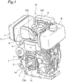
- Fig. 1 is a perspective view showing an engine of a first embodiment of the present disclosure.
- the engine 10 is an air-cooled single cylinder diesel engine.
- the engine 10 has a cylinder block 1, a cylinder head 2, an exhaust duct 3, a fuel tank 8, and an air cleaner 9.
- the cylinder head 2 is fitted to an upper portion of the cylinder block 1, the cylinder head 2 being fitted with the exhaust duct 3, the fuel tank 8, and the air cleaner 9.
- Fig. 2 is a simplified sectional view of the cylinder block 1 and the cylinder head 2.
- the cylinder block 1 has a cylinder 4 and a crankcase 5 fitted to the cylinder 4.
- a piston 11 is reciprocably disposed within the cylinder 4.
- a crankshaft 13 is coupled via a con rod 12 to the piston 11.
- the crankshaft 13 is disposed within the crankcase 5.
- the cylinder head 2 is fitted to the cylinder 4 of the cylinder block 1.
- a combustion chamber 15 is defined by a space enclosed by the cylinder head 2, an inner surface of the cylinder 4, and the piston 11.
- the cylinder head 2 has an intake port 21 and an exhaust port 22.
- the intake port 21 and the exhaust port 22 communicate with the interior (the combustion chamber 15) of the cylinder 4.
- the intake port 21 communicates with the air cleaner 9 (see Fig. 1 ).
- the exhaust port 22 communicates with the exhaust duct 3 (see Fig. 1 ).
- the intake port 21 includes an intake valve 23 that opens or closes between the intake port 21 and the combustion chamber 15.
- the exhaust port 22 includes an exhaust valve 24 that opens or closes between the exhaust port 22 and the combustion chamber 15.
- the cylinder head 2 includes a fuel injection nozzle 25 for injecting fuel into the combustion chamber 15.
- the fuel injection nozzle 25 communicates with the fuel tank 8 (see Fig. 1 ) .
- the cylinder block 1 has a load-side end face 1a from which an end 13a on the load side of the crankshaft 13 protrudes.
- a load member not shown (such as a fluid pressure pump or a pulley) is connected to the load-side end 13a of the crankshaft 13.
- a cooling fan not shown is connected to an end opposite to the load-side end 13a of the crankshaft 13.
- the exhaust duct 3 has a catalyst storage case 6 and an exhaust muffler 7.
- the catalyst storage case 6 is fitted to the cylinder head 2 and communicates with the exhaust port 22 of the cylinder head 2.
- the catalyst storage case 6 is disposed toward the load-side end face 1a of the cylinder block 1.
- the exhaust muffler 7 communicates with the catalyst storage case 6.
- air in the atmosphere is supplied, through the air cleaner 9, from the intake port 21 of the cylinder head 2 into the combustion chamber 15, while diesel fuel in the fuel tank 8 is fed from the fuel injection nozzle 25 into the combustion chamber 15 so that diesel fuel is combusted in the combustion chamber 15.
- This allows the piston 11 to move so that the crankshaft 13 turns around a shaft center L, driving the load member connected to the load-side end 13a of the crankshaft 13.
- High temperature exhaust gas in the combustion chamber 15 is discharged from the exhaust port 22 of the cylinder head 2 through the catalyst storage case 6 and the exhaust muffler 7, in the mentioned order, into the atmosphere while lowering the temperature.
- Fig. 3 is a perspective view of the exhaust duct 3.
- the catalyst storage case 6 and the exhaust muffler 7 are integrally connected to each other. That is, a case body 60 of the catalyst storage case 6 and a case body 70 of the exhaust muffler 7 are integrated.
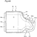
- Fig. 4A is a front view of the catalyst storage case 6.
- Fig. 4B is a left side view of the catalyst storage case 6.
- Fig. 4C is a sectional view of the catalyst storage case 6, as seen from the front.
- the catalyst storage case 6 has the case body 60 and two, first and second oxidation catalysts 61 and 62.
- the case body 60 has an inlet 60a, an outlet 60b, and an exhaust passage 60c extending from the inlet 60a to the outlet 60b for allowing exhaust gas to pass therethrough.
- the inlet 60a communicates with the exhaust port 22 of the cylinder head 2.
- the outlet 60b communicates with the exhaust muffler 7.
- the case body 60 has a first half 161 and a second half 162.
- the first half 161 and the second half 162 are joined together by welding.
- the first half 161 has a flange 167 toward the inlet 60a.
- the flange 167 has a hole 167a.
- a bolt 100 shown in Fig. 1 is inserted into the hole 167a.
- the inlet 60a of the case body 60 is connected via a seal member to the exhaust port 22 of the cylinder head 2.
- An end plate 163 is fitted to the outlet 60b of the case body 60.
- the end plate 163 is fitted with a first tubular part 164 and a second tubular part 165 that pass therethrough. Portions toward the inlet 60a of the first and second tubular parts 164 and 165 are supported by a support plate 166.
- the support plate 166 is fitted to the interior of the case body 60. This allows the inside and the outside of the case body 60 to communicate with each other via the first and second tubular parts 164 and 165.
- the first and the second tubular parts 164 and 165 are arrayed in a direction intersecting the direction along which the exhaust passage 60c extends. Describing specifically, the direction of array of the first and second tubular parts 164 and 165 is orthogonal to the direction of extension of the exhaust passage 60c.
- a portion 160 of the case body 60 between the inlet 60a and the support plate 166 is formed in a flared manner such that the exhaust passage 60c flares from the inlet 60a toward the support plate 166.
- the flared portion 160 is formed so as to introduce exhaust gas into the first and second tubular parts 164 and 165.
- An upper wall 160a of the flared portion 160 includes three inclined surfaces a1, a2, and a3 each having a different inclination.
- the first and the second oxidation catalysts 61 and 62 are arranged in the exhaust passage 60c. That is, the first oxidation catalyst 61 is inserted into the first tubular part 164, while the second oxidation catalyst 62 is inserted into the second tubular part 165.
- the first and the second oxidation catalysts 61 and 62 are arrayed in a direction intersecting the direction along which the execute passage 60c extends. Describing specifically, the direction of array of the first and second oxidation catalysts 61 and 62 is orthogonal to the direction of extension of the exhaust passage 60c. To further describe, the first and second oxidation catalysts 61 and 62 are arrayed in a direction orthogonal to the shaft center L (see Fig. 1 ) of the crankshaft 13. That is, the shaft center L of the crankshaft 13 extends in a direction orthogonal to the plane of Fig. 4C , while the first and second oxidation catalysts 61 and 62 are arrayed vertically on the plane of Fig. 4C .
- the first and the second oxidation catalysts 61 and 62 are of a flattened cylindrical shape.
- the first and second oxidation catalysts 61 and 62 are monolith carriers made of ceramic such as cordierite and have, to increase its specific surface area, a polygonal section partitioned by lattice-shaped or honeycomb-shaped porous partition walls. These partitions walls include a multiplicity of through holes formed in parallel to each other with exhaust gas entrances and exits alternately sealed.
- the partition walls carry catalyst metal such as platinum to thereby exhibit an oxidation catalytic function.
- the catalyst body may have a structure for increasing the specific surface area, and, for example, it may be a mesh ring including a plurality of lattice-shaped metal partition plates arranged therein.
- platinum is used as the catalyst metal, palladium, rhodium, iridium, etc. may be used without being limited thereto.
- the first and the second oxidation catalysts 61 and 62 capture PM (suspended particulate matter) in exhaust gas by the porous partition walls.
- the first and second oxidation catalysts 61 and 62 impart an oxidizing power to nitrogen oxide (NOx), nitrogen monoxide (NO), carbon monoxide (CO), hydrocarbon (HC), etc. in exhaust gas by carrying of the catalyst metal, to generate carbon dioxide, water, nitrogen dioxide NO2, etc.
- the oxidizing power of large amounts of NO2, etc. generated in exhaust gas by the catalyst metal and high temperature of exhaust gas in the vicinity of the exhaust port 22 are utilized to continuously oxidize the collected PM, for combustion and removal.
- Fig. 5 is a sectional view of the exhaust duct 3, as seen from the plane.
- the case body 70 of the exhaust muffler 7 has a first half 171 and a second half 172.
- the first half 171 and the second half 172 are joined together by welding.
- the case body 60 of the catalyst storage case 6 is fitted to the first half 171 in a penetrating manner. That is, the first half 171 and the case body 60 are integrally connected together by welding. The first half 171 and the case body 60 may be integrally connected together by bolts.
- An internal pipe 173 and a discharge pipe 174 are arranged within the interior of the case body 70 of the exhaust muffler 7.
- the interior of the case body 70 is partitioned by a partition plate 175 into a first space S1 and a second space S2.
- the case body 60 (first and second oxidation catalysts 61 and 62) enters the first space S1.
- the internal pipe 173 extends through the partition plate 175 to allow the first space S1 and the second space S2 to communicate with each other.
- the discharge pipe 174 extends through the partition plate 175 and the second half 172 to allow the second space S2 and the exterior of the case body 70 to communicate with each other.
- exhaust gas passing through the first and the second oxidation catalysts 61 and 62 enters the first space S1 and thereafter passes through the internal pipe, entering the second space S2. Afterward, exhaust gas flows from the second space S2 through the discharge pipe 174, being discharged to the outside of the case body 70.
- the first and the second oxidation catalysts 61 and 62 are contained and are arrayed in a direction intersecting the direction along which the exhaust passage 60c extends.
- the first and the second oxidation catalysts 61 and 62 experiences clogging.
- only the clogged second oxidation catalyst 62 may be replaced and the unclogged first oxidation catalyst 61 may be used intactly, thus enabling the waste of the oxidation catalysts 61 and 62 to be reduced.
- the catalyst storage case 6 and the exhaust muffler 7 are integrally connected to each other, with the result that the number of components of the exhaust duct 3 can be reduced, facilitating the assembly of the exhaust duct 3.
- the waste of the oxidation catalysts 61 and 62 can be reduced when replacing the oxidation catalysts 61 and 62.
- the thickness of the catalyst storage case 6 in the direction of the shaft center L of the crankshaft 13 can be suppressed regardless of the presence of the two oxidation catalysts 61 and 62. Therefore, the catalyst storage case 6 can be restrained from protruding toward the load of the cylinder block 1, preventing the catalyst storage case 6 from interfering with the load member when connecting the load member to the load-side end 13a of the crankshaft 13 of the cylinder block 1.
- first and second oxidation catalysts 61 and 62 are arrayed in a direction orthogonal to the shaft center L of the crankshaft 13, the first and second oxidation catalysts 61 and 62 cannot be arrayed along the shaft center L of the crankshaft 13, thus enabling the thickness of the catalyst storage case 6 in the direction of the shaft center L of the crankshaft 13 to be further suppressed.
- Fig. 6 is a sectional view showing a catalyst storage case of a second embodiment of the present disclosure.
- the second embodiment differs from the first embodiment only in the configuration of a baffle plate. Only this different configuration will be described below.
- the same reference numerals as those in the first embodiment denote the same configurations as those in the first embodiment and therefore will not again be described.
- a catalyst storage case 6A of the second embodiment has a baffle plate 65.
- the baffle plate 65 is disposed between the first and second oxidation catalysts 61, 62 and the inlet 60a. That is, the baffle plate 65 is disposed in the flared portion 160 of the case body 60.
- the baffle plate 65 leads exhaust gas to each of the first and second oxidation catalysts 61 and 62.
- the baffle plate 65 is disposed so as to substantially uniformly lead exhaust gas to each of the oxidation catalysts 61 and 62. Describing specifically, the baffle plate 65 is disposed on a plane extending between the first and second oxidation catalysts 61 and 62 and through the center of the inlet 60a.
- the baffle plate 65 leads exhaust gas to each of the oxidation catalysts 61 and 62, it can substantially uniformly lead exhaust gas to each of the oxidation catalysts 61 and 62 so that the unevenness of occurrence of clogging in the first and second oxidation catalysts 61 and 62 can be reduced.
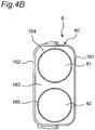
- Fig. 7 is a perspective view showing an exhaust duct of a third embodiment of the present disclosure.
- the third embodiment differs from the first embodiment only in the configuration of the catalyst storage case of the exhaust duct. Only this different configuration will be described below.
- the same reference numerals as those in the first embodiment denote the same configurations as those in the first embodiment and therefore will not again be described.
- a catalyst storage case 6B of an exhaust duct 3B differs from the catalyst storage case 6 of the first embodiment ( Fig. 4A ) in the shape of a flared portion 160B of a case body 60B.
- the upper wall 160a of the flared portion 160 of the first embodiment ( Fig. 4A ) includes three inclined surfaces a1, a2, and a3 each having a different inclination
- an upper wall 160b of the flared portion 160B of the third embodiment ( Fig. 7 ) includes two inclined surfaces b1 and b2 each having a different inclination.
- the upstream inclined surface b1 of Fig. 7 corresponds to the two upstream inclined surfaces a1 and a2 of Fig. 4A
- the downstream inclined surface b2 of Fig 7 corresponds to the downstream inclined surface a3 of Fig. 4A .
- a multicylinder diesel engine may be used.
- the two oxidation catalysts are disposed in the above embodiments, three or more oxidation catalysts may be disposed.
- the two oxidation catalysts are arrayed in a direction orthogonal to the direction along which the exhaust passage extends in the above embodiments, they may be arrayed in a direction intersecting at a predetermined angle, instead of a right angle, with the direction of extension of the exhaust passage.
- the two oxidation catalysts are arrayed in a direction orthogonal to the shaft center of the crankshaft in the above embodiments, they may be arrayed in a direction intersecting at a predetermined angle, instead of a right angle, with the shaft center of the crankshaft.
- the catalyst storage case and the exhaust muffler are integrally connected together by welding in the above embodiments, the catalyst storage case (case body) and the exhaust muffler (case body) may be integrally seamlessly continuously connected together by pressing a single metal plate.
Landscapes
- Chemical & Material Sciences (AREA)
- Engineering & Computer Science (AREA)
- Chemical Kinetics & Catalysis (AREA)
- Combustion & Propulsion (AREA)
- Mechanical Engineering (AREA)
- General Engineering & Computer Science (AREA)
- Health & Medical Sciences (AREA)
- Toxicology (AREA)
- Materials Engineering (AREA)
- Exhaust Gas After Treatment (AREA)
- Exhaust Silencers (AREA)
- Exhaust Gas Treatment By Means Of Catalyst (AREA)
Claims (2)
- Moteur (10) comprenant :un bloc cylindre (1) ayant un cylindre (4) ;une tête de cylindre (2) fixée au bloc cylindre (1), la tête de cylindre (2) ayant un port d'échappement (22) en communication avec l'intérieur du cylindre (4) ; etun boîtier de stockage de catalyseur (6) fixé à la tête de cylindre (2), le boîtier de stockage de catalyseur (6) comprenant :un corps de boîtier (60) ayant un orifice d'entrée (60a), un orifice de sortie (60b) et un passage d'échappement (60c) s'étendant de l'orifice d'entrée (60a) à l'orifice de sortie (60b) pour permettre à un gaz d'échappement de passer à travers celui-ci ; etune pluralité de catalyseurs d'oxydation (61 ; 62) disposés dans le passage d'échappement (60c) du corps de boîtier (60), dans lequella pluralité de catalyseurs d'oxydation sont disposés en rangée suivant une direction entrant en intersection avec une direction le long de laquelle s'étend le passage d'échappement (60c) ; dans lequell'orifice d'entrée du boîtier de stockage de catalyseur (6) est en communication avec le port d'échappement (22) de la tête de cylindre (2) ;le bloc cylindre (1) a un piston (11) disposé dans le cylindre (4) et un vilebrequin (13) couplé au piston (11),le bloc cylindre (1) a une face d'extrémité côté chargement (1a) à partir de laquelle une extrémité côté chargement (13a) du vilebrequin (21) fait saillie, le moteur (10) étant caractérisé en ce que :le boîtier de stockage de catalyseur (6) est disposé vers la face d'extrémité côté chargement (1a) du bloc cylindre (1), etles axes longitudinaux de la pluralité des catalyseurs d'oxydation (61 ; 62) dans le boîtier de stockage de catalyseur (6) sont dans un plan orthogonal à l'axe du centre de l'arbre (L) du vilebrequin (13).
- Moteur selon la revendication 1, dans lequel le boîtier de stockage de catalyseur (6) comprend en outre :
une plaque déflectrice (65) disposée entre les catalyseurs d'oxydation (61 ; 62) et l'orifice d'entrée (60a) dans le passage d'échappement (60c) du corps de boîtier (60) pour orienter le gaz d'échappement vers chacun des catalyseurs d'oxydation (61 ; 62).
Applications Claiming Priority (2)
| Application Number | Priority Date | Filing Date | Title |
|---|---|---|---|
| JP2014017533A JP6165072B2 (ja) | 2014-01-31 | 2014-01-31 | エンジン |
| PCT/JP2015/050326 WO2015115144A1 (fr) | 2014-01-31 | 2015-01-08 | Carter de catalyseur, conduit d'échappement et moteur |
Publications (3)
| Publication Number | Publication Date |
|---|---|
| EP3101246A1 EP3101246A1 (fr) | 2016-12-07 |
| EP3101246A4 EP3101246A4 (fr) | 2017-08-30 |
| EP3101246B1 true EP3101246B1 (fr) | 2020-03-04 |
Family
ID=53756722
Family Applications (1)
| Application Number | Title | Priority Date | Filing Date |
|---|---|---|---|
| EP15742981.2A Active EP3101246B1 (fr) | 2014-01-31 | 2015-01-08 | Carter de catalyseur, conduit d'échappement et moteur |
Country Status (6)
| Country | Link |
|---|---|
| US (1) | US10113467B2 (fr) |
| EP (1) | EP3101246B1 (fr) |
| JP (1) | JP6165072B2 (fr) |
| KR (2) | KR20160108366A (fr) |
| CN (1) | CN105940196B (fr) |
| WO (1) | WO2015115144A1 (fr) |
Families Citing this family (3)
| Publication number | Priority date | Publication date | Assignee | Title |
|---|---|---|---|---|
| DE102016113756A1 (de) * | 2016-07-26 | 2018-02-01 | Motorenfabrik Hatz Gmbh & Co Kg | Schalldämpfer für Einzylinder-Dieselmotor |
| JP6866732B2 (ja) * | 2017-04-03 | 2021-04-28 | スズキ株式会社 | 鞍乗型車両の排気装置 |
| WO2022087279A1 (fr) * | 2020-10-22 | 2022-04-28 | Cummins Emission Solutions Inc. | Système de post-traitement des gaz d'échappement |
Family Cites Families (15)
| Publication number | Priority date | Publication date | Assignee | Title |
|---|---|---|---|---|
| JPS6412015A (en) * | 1987-07-01 | 1989-01-17 | Hino Motors Ltd | Exhaust gas purification device |
| JPH0610409B2 (ja) * | 1987-10-19 | 1994-02-09 | 新キャタピラー三菱株式会社 | エンジンのスモーク低減装置 |
| US4884398A (en) | 1987-10-19 | 1989-12-05 | Shin Caterpillar Mitsubishi Ltd. | Method of and apparatus for reducing engine smoke emissions |
| JPH0610410B2 (ja) * | 1987-10-19 | 1994-02-09 | 新キャタピラー三菱株式会社 | エンジンのスモーク低減方法 |
| JPH068722U (ja) * | 1992-07-08 | 1994-02-04 | 日産ディーゼル工業株式会社 | 内燃機関の触媒装置 |
| JPH0814033A (ja) * | 1994-06-24 | 1996-01-16 | Caterpillar Inc | 内燃エンジン用モジュール触媒コンバータとマフラー |
| JP4330048B2 (ja) * | 1999-06-11 | 2009-09-09 | ヤマハ発動機株式会社 | 船外機用多気筒4サイクルエンジン |
| JP2003083046A (ja) * | 2001-09-11 | 2003-03-19 | Honda Motor Co Ltd | エンジンの排気系冷却装置 |
| JP2003214142A (ja) * | 2002-01-24 | 2003-07-30 | Ooden:Kk | ディーゼル微粒子除去装置及び該除去装置を備えるディーゼル車 |
| JP2003214143A (ja) * | 2002-01-24 | 2003-07-30 | Ooden:Kk | ディーゼル微粒子除去装置及び該除去装置を備えるディーゼル車 |
| JP2006009648A (ja) * | 2004-06-24 | 2006-01-12 | Honda Motor Co Ltd | 自動二輪車の排気浄化装置 |
| JP4654763B2 (ja) * | 2005-05-23 | 2011-03-23 | スズキ株式会社 | エンジンの排気装置 |
| JP5046674B2 (ja) * | 2007-02-07 | 2012-10-10 | 本田技研工業株式会社 | 自動二輪車の触媒配置構造 |
| JP5846381B2 (ja) | 2012-05-18 | 2016-01-20 | 三菱自動車工業株式会社 | 内燃機関の排気浄化装置 |
| WO2015015619A1 (fr) | 2013-08-01 | 2015-02-05 | Miyashita Michiko | Système de purification de gaz d'échappement |
-
2014
- 2014-01-31 JP JP2014017533A patent/JP6165072B2/ja active Active
-
2015
- 2015-01-08 US US15/115,395 patent/US10113467B2/en active Active
- 2015-01-08 KR KR1020167020077A patent/KR20160108366A/ko not_active Application Discontinuation
- 2015-01-08 CN CN201580006584.6A patent/CN105940196B/zh not_active Expired - Fee Related
- 2015-01-08 KR KR1020207012085A patent/KR20200047756A/ko not_active IP Right Cessation
- 2015-01-08 EP EP15742981.2A patent/EP3101246B1/fr active Active
- 2015-01-08 WO PCT/JP2015/050326 patent/WO2015115144A1/fr active Application Filing
Non-Patent Citations (1)
| Title |
|---|
| None * |
Also Published As
| Publication number | Publication date |
|---|---|
| JP2015143510A (ja) | 2015-08-06 |
| KR20200047756A (ko) | 2020-05-07 |
| CN105940196B (zh) | 2019-02-15 |
| EP3101246A1 (fr) | 2016-12-07 |
| JP6165072B2 (ja) | 2017-07-19 |
| WO2015115144A1 (fr) | 2015-08-06 |
| KR20160108366A (ko) | 2016-09-19 |
| CN105940196A (zh) | 2016-09-14 |
| US10113467B2 (en) | 2018-10-30 |
| US20170002712A1 (en) | 2017-01-05 |
| EP3101246A4 (fr) | 2017-08-30 |
Similar Documents
| Publication | Publication Date | Title |
|---|---|---|
| US8015802B2 (en) | Exhaust gas purification device for internal combustion engine | |
| US9341096B2 (en) | Exhaust gas treatment device for use near an engine and motor vehicle having the device | |
| US7836688B2 (en) | Exhaust system | |
| US6767378B2 (en) | Exhaust gas purifying system for internal combustion engine | |
| JP5010679B2 (ja) | 濾過効率を改善させた副流フィルタ | |
| JP2009091982A (ja) | 排気浄化装置 | |
| EP3101246B1 (fr) | Carter de catalyseur, conduit d'échappement et moteur | |
| WO2016194201A1 (fr) | Structure de tuyau d'échappement pour moteur à combustion interne | |
| JP2009197695A5 (fr) | ||
| JP5856641B2 (ja) | 排気ガス浄化装置 | |
| AU2019213090B2 (en) | Exhaust gas purification device | |
| JP2012140964A (ja) | 排気ガス浄化装置 | |
| CN103644015B (zh) | 发动机 | |
| WO2013005452A1 (fr) | Dispositif de purification de gaz d'échappement | |
| JP5368839B2 (ja) | エンジン | |
| US6193935B1 (en) | Catalytic converter | |
| JP2013217378A (ja) | エンジン | |
| JP5368838B2 (ja) | エンジン | |
| US20150064079A1 (en) | Catalyst substrate module for exhaust aftertreatment system | |
| KR102224012B1 (ko) | 배기가스 정화 시스템 | |
| KR20210056236A (ko) | 촉매 컨버터, 배기 가스 후처리 시스템 및 내연 기관 | |
| JP2014211123A (ja) | 内燃機関のディーゼルパティキュレートフィルタ | |
| JP2019214963A (ja) | 排気系構造 |
Legal Events
| Date | Code | Title | Description |
|---|---|---|---|
| PUAI | Public reference made under article 153(3) epc to a published international application that has entered the european phase |
Free format text: ORIGINAL CODE: 0009012 |
|
| STAA | Information on the status of an ep patent application or granted ep patent |
Free format text: STATUS: REQUEST FOR EXAMINATION WAS MADE |
|
| 17P | Request for examination filed |
Effective date: 20160727 |
|
| AK | Designated contracting states |
Kind code of ref document: A1 Designated state(s): AL AT BE BG CH CY CZ DE DK EE ES FI FR GB GR HR HU IE IS IT LI LT LU LV MC MK MT NL NO PL PT RO RS SE SI SK SM TR |
|
| AX | Request for extension of the european patent |
Extension state: BA ME |
|
| DAX | Request for extension of the european patent (deleted) | ||
| A4 | Supplementary search report drawn up and despatched |
Effective date: 20170802 |
|
| RIC1 | Information provided on ipc code assigned before grant |
Ipc: F01N 1/00 20060101ALI20170727BHEP Ipc: F01N 13/00 20100101ALI20170727BHEP Ipc: F01N 3/10 20060101ALI20170727BHEP Ipc: F01N 3/00 20060101ALI20170727BHEP Ipc: F01N 3/28 20060101AFI20170727BHEP Ipc: F01N 3/24 20060101ALI20170727BHEP |
|
| STAA | Information on the status of an ep patent application or granted ep patent |
Free format text: STATUS: EXAMINATION IS IN PROGRESS |
|
| 17Q | First examination report despatched |
Effective date: 20190221 |
|
| GRAP | Despatch of communication of intention to grant a patent |
Free format text: ORIGINAL CODE: EPIDOSNIGR1 |
|
| STAA | Information on the status of an ep patent application or granted ep patent |
Free format text: STATUS: GRANT OF PATENT IS INTENDED |
|
| INTG | Intention to grant announced |
Effective date: 20190924 |
|
| GRAS | Grant fee paid |
Free format text: ORIGINAL CODE: EPIDOSNIGR3 |
|
| GRAA | (expected) grant |
Free format text: ORIGINAL CODE: 0009210 |
|
| STAA | Information on the status of an ep patent application or granted ep patent |
Free format text: STATUS: THE PATENT HAS BEEN GRANTED |
|
| AK | Designated contracting states |
Kind code of ref document: B1 Designated state(s): AL AT BE BG CH CY CZ DE DK EE ES FI FR GB GR HR HU IE IS IT LI LT LU LV MC MK MT NL NO PL PT RO RS SE SI SK SM TR |
|
| REG | Reference to a national code |
Ref country code: GB Ref legal event code: FG4D |
|
| REG | Reference to a national code |
Ref country code: CH Ref legal event code: EP |
|
| REG | Reference to a national code |
Ref country code: AT Ref legal event code: REF Ref document number: 1240615 Country of ref document: AT Kind code of ref document: T Effective date: 20200315 |
|
| REG | Reference to a national code |
Ref country code: DE Ref legal event code: R096 Ref document number: 602015048176 Country of ref document: DE |
|
| REG | Reference to a national code |
Ref country code: IE Ref legal event code: FG4D |
|
| PG25 | Lapsed in a contracting state [announced via postgrant information from national office to epo] |
Ref country code: RS Free format text: LAPSE BECAUSE OF FAILURE TO SUBMIT A TRANSLATION OF THE DESCRIPTION OR TO PAY THE FEE WITHIN THE PRESCRIBED TIME-LIMIT Effective date: 20200304 Ref country code: NO Free format text: LAPSE BECAUSE OF FAILURE TO SUBMIT A TRANSLATION OF THE DESCRIPTION OR TO PAY THE FEE WITHIN THE PRESCRIBED TIME-LIMIT Effective date: 20200604 Ref country code: FI Free format text: LAPSE BECAUSE OF FAILURE TO SUBMIT A TRANSLATION OF THE DESCRIPTION OR TO PAY THE FEE WITHIN THE PRESCRIBED TIME-LIMIT Effective date: 20200304 |
|
| REG | Reference to a national code |
Ref country code: NL Ref legal event code: MP Effective date: 20200304 |
|
| PG25 | Lapsed in a contracting state [announced via postgrant information from national office to epo] |
Ref country code: BG Free format text: LAPSE BECAUSE OF FAILURE TO SUBMIT A TRANSLATION OF THE DESCRIPTION OR TO PAY THE FEE WITHIN THE PRESCRIBED TIME-LIMIT Effective date: 20200604 Ref country code: SE Free format text: LAPSE BECAUSE OF FAILURE TO SUBMIT A TRANSLATION OF THE DESCRIPTION OR TO PAY THE FEE WITHIN THE PRESCRIBED TIME-LIMIT Effective date: 20200304 Ref country code: LV Free format text: LAPSE BECAUSE OF FAILURE TO SUBMIT A TRANSLATION OF THE DESCRIPTION OR TO PAY THE FEE WITHIN THE PRESCRIBED TIME-LIMIT Effective date: 20200304 Ref country code: HR Free format text: LAPSE BECAUSE OF FAILURE TO SUBMIT A TRANSLATION OF THE DESCRIPTION OR TO PAY THE FEE WITHIN THE PRESCRIBED TIME-LIMIT Effective date: 20200304 Ref country code: GR Free format text: LAPSE BECAUSE OF FAILURE TO SUBMIT A TRANSLATION OF THE DESCRIPTION OR TO PAY THE FEE WITHIN THE PRESCRIBED TIME-LIMIT Effective date: 20200605 |
|
| REG | Reference to a national code |
Ref country code: LT Ref legal event code: MG4D |
|
| PG25 | Lapsed in a contracting state [announced via postgrant information from national office to epo] |
Ref country code: NL Free format text: LAPSE BECAUSE OF FAILURE TO SUBMIT A TRANSLATION OF THE DESCRIPTION OR TO PAY THE FEE WITHIN THE PRESCRIBED TIME-LIMIT Effective date: 20200304 |
|
| REG | Reference to a national code |
Ref country code: DE Ref legal event code: R082 Ref document number: 602015048176 Country of ref document: DE Representative=s name: DOMPATENT VON KREISLER SELTING WERNER - PARTNE, DE Ref country code: DE Ref legal event code: R081 Ref document number: 602015048176 Country of ref document: DE Owner name: YANMAR POWER TECHNOLOGY CO., LTD., JP Free format text: FORMER OWNER: YANMAR CO., LTD., OSAKA-SHI, JP |
|
| PG25 | Lapsed in a contracting state [announced via postgrant information from national office to epo] |
Ref country code: IS Free format text: LAPSE BECAUSE OF FAILURE TO SUBMIT A TRANSLATION OF THE DESCRIPTION OR TO PAY THE FEE WITHIN THE PRESCRIBED TIME-LIMIT Effective date: 20200704 Ref country code: SK Free format text: LAPSE BECAUSE OF FAILURE TO SUBMIT A TRANSLATION OF THE DESCRIPTION OR TO PAY THE FEE WITHIN THE PRESCRIBED TIME-LIMIT Effective date: 20200304 Ref country code: LT Free format text: LAPSE BECAUSE OF FAILURE TO SUBMIT A TRANSLATION OF THE DESCRIPTION OR TO PAY THE FEE WITHIN THE PRESCRIBED TIME-LIMIT Effective date: 20200304 Ref country code: EE Free format text: LAPSE BECAUSE OF FAILURE TO SUBMIT A TRANSLATION OF THE DESCRIPTION OR TO PAY THE FEE WITHIN THE PRESCRIBED TIME-LIMIT Effective date: 20200304 Ref country code: SM Free format text: LAPSE BECAUSE OF FAILURE TO SUBMIT A TRANSLATION OF THE DESCRIPTION OR TO PAY THE FEE WITHIN THE PRESCRIBED TIME-LIMIT Effective date: 20200304 Ref country code: CZ Free format text: LAPSE BECAUSE OF FAILURE TO SUBMIT A TRANSLATION OF THE DESCRIPTION OR TO PAY THE FEE WITHIN THE PRESCRIBED TIME-LIMIT Effective date: 20200304 Ref country code: RO Free format text: LAPSE BECAUSE OF FAILURE TO SUBMIT A TRANSLATION OF THE DESCRIPTION OR TO PAY THE FEE WITHIN THE PRESCRIBED TIME-LIMIT Effective date: 20200304 Ref country code: PT Free format text: LAPSE BECAUSE OF FAILURE TO SUBMIT A TRANSLATION OF THE DESCRIPTION OR TO PAY THE FEE WITHIN THE PRESCRIBED TIME-LIMIT Effective date: 20200729 Ref country code: ES Free format text: LAPSE BECAUSE OF FAILURE TO SUBMIT A TRANSLATION OF THE DESCRIPTION OR TO PAY THE FEE WITHIN THE PRESCRIBED TIME-LIMIT Effective date: 20200304 |
|
| REG | Reference to a national code |
Ref country code: AT Ref legal event code: MK05 Ref document number: 1240615 Country of ref document: AT Kind code of ref document: T Effective date: 20200304 |
|
| REG | Reference to a national code |
Ref country code: DE Ref legal event code: R097 Ref document number: 602015048176 Country of ref document: DE |
|
| PLBE | No opposition filed within time limit |
Free format text: ORIGINAL CODE: 0009261 |
|
| STAA | Information on the status of an ep patent application or granted ep patent |
Free format text: STATUS: NO OPPOSITION FILED WITHIN TIME LIMIT |
|
| PG25 | Lapsed in a contracting state [announced via postgrant information from national office to epo] |
Ref country code: DK Free format text: LAPSE BECAUSE OF FAILURE TO SUBMIT A TRANSLATION OF THE DESCRIPTION OR TO PAY THE FEE WITHIN THE PRESCRIBED TIME-LIMIT Effective date: 20200304 Ref country code: AT Free format text: LAPSE BECAUSE OF FAILURE TO SUBMIT A TRANSLATION OF THE DESCRIPTION OR TO PAY THE FEE WITHIN THE PRESCRIBED TIME-LIMIT Effective date: 20200304 |
|
| 26N | No opposition filed |
Effective date: 20201207 |
|
| PG25 | Lapsed in a contracting state [announced via postgrant information from national office to epo] |
Ref country code: SI Free format text: LAPSE BECAUSE OF FAILURE TO SUBMIT A TRANSLATION OF THE DESCRIPTION OR TO PAY THE FEE WITHIN THE PRESCRIBED TIME-LIMIT Effective date: 20200304 Ref country code: PL Free format text: LAPSE BECAUSE OF FAILURE TO SUBMIT A TRANSLATION OF THE DESCRIPTION OR TO PAY THE FEE WITHIN THE PRESCRIBED TIME-LIMIT Effective date: 20200304 |
|
| PG25 | Lapsed in a contracting state [announced via postgrant information from national office to epo] |
Ref country code: MC Free format text: LAPSE BECAUSE OF FAILURE TO SUBMIT A TRANSLATION OF THE DESCRIPTION OR TO PAY THE FEE WITHIN THE PRESCRIBED TIME-LIMIT Effective date: 20200304 |
|
| REG | Reference to a national code |
Ref country code: CH Ref legal event code: PL |
|
| PG25 | Lapsed in a contracting state [announced via postgrant information from national office to epo] |
Ref country code: LU Free format text: LAPSE BECAUSE OF NON-PAYMENT OF DUE FEES Effective date: 20210108 |
|
| REG | Reference to a national code |
Ref country code: BE Ref legal event code: MM Effective date: 20210131 |
|
| PG25 | Lapsed in a contracting state [announced via postgrant information from national office to epo] |
Ref country code: FR Free format text: LAPSE BECAUSE OF NON-PAYMENT OF DUE FEES Effective date: 20210131 |
|
| PG25 | Lapsed in a contracting state [announced via postgrant information from national office to epo] |
Ref country code: LI Free format text: LAPSE BECAUSE OF NON-PAYMENT OF DUE FEES Effective date: 20210131 Ref country code: CH Free format text: LAPSE BECAUSE OF NON-PAYMENT OF DUE FEES Effective date: 20210131 |
|
| PG25 | Lapsed in a contracting state [announced via postgrant information from national office to epo] |
Ref country code: IE Free format text: LAPSE BECAUSE OF NON-PAYMENT OF DUE FEES Effective date: 20210108 |
|
| PGFP | Annual fee paid to national office [announced via postgrant information from national office to epo] |
Ref country code: GB Payment date: 20220119 Year of fee payment: 8 Ref country code: DE Payment date: 20220119 Year of fee payment: 8 |
|
| PG25 | Lapsed in a contracting state [announced via postgrant information from national office to epo] |
Ref country code: BE Free format text: LAPSE BECAUSE OF NON-PAYMENT OF DUE FEES Effective date: 20210131 |
|
| PG25 | Lapsed in a contracting state [announced via postgrant information from national office to epo] |
Ref country code: IT Free format text: LAPSE BECAUSE OF NON-PAYMENT OF DUE FEES Effective date: 20210108 |
|
| PG25 | Lapsed in a contracting state [announced via postgrant information from national office to epo] |
Ref country code: HU Free format text: LAPSE BECAUSE OF FAILURE TO SUBMIT A TRANSLATION OF THE DESCRIPTION OR TO PAY THE FEE WITHIN THE PRESCRIBED TIME-LIMIT; INVALID AB INITIO Effective date: 20150108 |
|
| PG25 | Lapsed in a contracting state [announced via postgrant information from national office to epo] |
Ref country code: CY Free format text: LAPSE BECAUSE OF FAILURE TO SUBMIT A TRANSLATION OF THE DESCRIPTION OR TO PAY THE FEE WITHIN THE PRESCRIBED TIME-LIMIT Effective date: 20200304 |
|
| REG | Reference to a national code |
Ref country code: DE Ref legal event code: R119 Ref document number: 602015048176 Country of ref document: DE |
|
| GBPC | Gb: european patent ceased through non-payment of renewal fee |
Effective date: 20230108 |
|
| PG25 | Lapsed in a contracting state [announced via postgrant information from national office to epo] |
Ref country code: GB Free format text: LAPSE BECAUSE OF NON-PAYMENT OF DUE FEES Effective date: 20230108 Ref country code: DE Free format text: LAPSE BECAUSE OF NON-PAYMENT OF DUE FEES Effective date: 20230801 |
|
| PG25 | Lapsed in a contracting state [announced via postgrant information from national office to epo] |
Ref country code: MK Free format text: LAPSE BECAUSE OF FAILURE TO SUBMIT A TRANSLATION OF THE DESCRIPTION OR TO PAY THE FEE WITHIN THE PRESCRIBED TIME-LIMIT Effective date: 20200304 |