EP3101202B1 - Schliessvorrichtung mit panikschaltung - Google Patents
Schliessvorrichtung mit panikschaltung Download PDFInfo
- Publication number
- EP3101202B1 EP3101202B1 EP15003581.4A EP15003581A EP3101202B1 EP 3101202 B1 EP3101202 B1 EP 3101202B1 EP 15003581 A EP15003581 A EP 15003581A EP 3101202 B1 EP3101202 B1 EP 3101202B1
- Authority
- EP
- European Patent Office
- Prior art keywords
- operating state
- nut
- activating unit
- closing
- closure device
- Prior art date
- Legal status (The legal status is an assumption and is not a legal conclusion. Google has not performed a legal analysis and makes no representation as to the accuracy of the status listed.)
- Active
Links
- 230000000903 blocking effect Effects 0.000 claims description 32
- 230000003213 activating effect Effects 0.000 claims 11
- 230000004913 activation Effects 0.000 description 22
- 238000010276 construction Methods 0.000 description 4
- 210000003813 thumb Anatomy 0.000 description 2
- 241001449342 Chlorocrambe hastata Species 0.000 description 1
- 230000000694 effects Effects 0.000 description 1
- 210000003746 feather Anatomy 0.000 description 1
Images
Classifications
-
- E—FIXED CONSTRUCTIONS
- E05—LOCKS; KEYS; WINDOW OR DOOR FITTINGS; SAFES
- E05B—LOCKS; ACCESSORIES THEREFOR; HANDCUFFS
- E05B13/00—Devices preventing the key or the handle or both from being used
- E05B13/002—Devices preventing the key or the handle or both from being used locking the handle
- E05B13/004—Devices preventing the key or the handle or both from being used locking the handle by locking the spindle, follower, or the like
-
- E—FIXED CONSTRUCTIONS
- E05—LOCKS; KEYS; WINDOW OR DOOR FITTINGS; SAFES
- E05B—LOCKS; ACCESSORIES THEREFOR; HANDCUFFS
- E05B13/00—Devices preventing the key or the handle or both from being used
- E05B13/10—Devices preventing the key or the handle or both from being used formed by a lock arranged in the handle
- E05B13/106—Devices preventing the key or the handle or both from being used formed by a lock arranged in the handle for handles pivoted about an axis perpendicular to the wing
- E05B13/108—Devices preventing the key or the handle or both from being used formed by a lock arranged in the handle for handles pivoted about an axis perpendicular to the wing the lock coaxial with spindle
-
- E—FIXED CONSTRUCTIONS
- E05—LOCKS; KEYS; WINDOW OR DOOR FITTINGS; SAFES
- E05B—LOCKS; ACCESSORIES THEREFOR; HANDCUFFS
- E05B65/00—Locks or fastenings for special use
- E05B65/10—Locks or fastenings for special use for panic or emergency doors
- E05B65/1086—Locks with panic function, e.g. allowing opening from the inside without a ley even when locked from the outside
Definitions
- the present invention relates to a locking device with an integrated in a lock housing closing and opening mechanism, wherein the closing and opening mechanism is blocked in a first operating state in a closed position and is in a second operating state in an open position, and with a trigger means for actuating the Closing and opening mechanism in the second operating state, which is operatively connected via a nut with the closing and opening mechanism.
- Such a closure device is well known in the art. Regularly, for example, a door is closed with such a closing device, the pusher then remains movable. There are locking systems in which in the closed position of a locking device, the pusher is blocked. Such locking systems are eg off US0159486 or off AT357431 known. It would be desirable if the blockage of the pusher in the closed position of the latch could be optionally canceled.
- the object of the present invention is to develop a locking device of the type mentioned in such a way that a locked door with a locked pusher can be opened manually.
- the trigger means comprises an activation unit which cancels the achieved by the electromagnetic door opener blockage of the closing and opening mechanism in the first operating state with manual operation by a user and thereby causes the second operating state of the open position.
- the activation unit cooperates with a blocking device which blocks the nut in the first operating state against rotation and releases it in the second operating state.
- a blocking device which blocks the nut in the first operating state against rotation and releases it in the second operating state.
- This construction makes it possible to easily influence the rotation of the nut.
- About the rotation of the nut is effected in the closing and opening mechanism that, for. a latch element and / or a locking element can withdraw from a closed position / can. So if these components are in a closed position, the blockage of the nut also leads to a blockage of the locking element and / or latch element.
- the blocking device comprises a blocking element, which in the first operating state is located at least partially in the movement path of the push rod and in the second operating state is pushed out of the movement path by the push rod. This optimizes the effect of the pushrod as a "spearhead".
- the blocking device is arranged transversely to the activation unit. This makes it possible to prevent the action of the activation unit from one side using the blocking device.
- the activation unit comprises a push rod that moves on actuation of the activation unit on a movement path. Such a push rod can be integrated in a conventional pusher. This allows the pushrod to be used as a "spear tip" to clear the way, so that the nut can rotate.
- Another advantage is also that the blocking element is biased in the direction of the movement path of the push rod. This ensures that the blocking element is always safely in the first operating state during automatic operations and can be brought out of this safe first operating state only by a manual action against the bias.
- the blocking element is a row of balls of several, abutting balls, which is guided in a spring housing, wherein in the first operating state, a ball with its half ball diameter in the movement path of the push rod and in the second operating state in the spring housing is pushed back. This can be done with little effort and low mechanical effort effective unlocking of the nut.
- the blocking element is a blocking pin, which in the first operating state extends into the movement path of the push rod, and in the second operating state is turned out of the movement path.
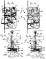
- Fig. 1a 1 is a schematic representation of a first embodiment of a closing device 1 intended to be installed in a door (not shown), so that a locking element 3 and / or a trapping element 5 protrude beyond a cuff rail 6 and can engage in adapted openings (not shown) of a striking plate (not shown).
- the closing device 1 comprises a lock housing 7, in which a closing and opening mechanism 9 is arranged.
- This closing and opening mechanism 9 is known per se and not the subject of the present invention. Of importance for the invention is only one nut 11, the rotatable (right / left in the plan view of Fig.
- a pusher device 17 is shown, which is operatively connected via the nut 11 with the closing and opening mechanism 9.
- the pusher device 17 comprises a pusher 19, in which an activation unit 21 is integrated, which is formed in the present embodiment as a push rod 22.
- the push rod 22 projects with a first end 23 out of the pusher 19, so that this free end 23 can be used as a push button, which can be actuated eg by means of thumb.
- An opposite second end 24 of the push rod 22 is convex and, in the illustrated embodiment, is a ball. In other embodiments, the convex end may be a hemisphere or a portion of a spherical surface.
- the push rod 22 is connected via a locking device 25 in the in Fig. 1b Locked position shown.
- a blocking device 27 with a blocking element 28.
- this comprises a spring channel 29, which thus extends transversely to the activation unit 21 and, in the present embodiment, also transversely to the push rod 22.
- the Spring channel 29 extends through a spring housing 30 adjoining the nut 11 and through a wall of the nut 11, into the nut opening.
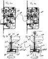
- the convex second end 24 presses against the first of the balls 31 in the spring channel 29 and pushes the whole ball chain against the spring force of the spring 33 in the direction of spring 33, so far, until the ball 31, which has been located with approximately its largest diameter exactly on the boundary between the spring housing 30 and wall of the nut 11, is now displaced in the spring housing 30, so that now an interface between two balls 31 exactly on the Border between spring housing 30 and wall of the nut 11 is located.
- the activation unit 21 and in the present embodiment, the push rod 22 can rotate this / these counterclockwise (arrow in FIG Fig. 2b ) and thereby lock on the locking device 25. Due to the small force acting on the aforementioned interface between the two balls 31, the nut 11 can now rotate, so that a manual opening by means of the pusher device 17 or by means of Pusher 19 is possible.
- the locking device 25 comprises in the present embodiment, a locking pin 25.1, which is mounted approximately perpendicular to the activation unit 21 and the push rod 22 and projects through an L-shaped recess 25.2, which serves as a latch pin guide.
- the locking pin 25.1 is located at a remote from the nut 11 end 25.3 of the L-shaped recess and in the in Fig. 2b the locking pin 25.1 is located on one of the nut 11 closer center position in the L-shaped recess 25.2 and in a locked in this second operating state position, so after rotation of the activation unit 21 and push rod 22, the locking pin is 25.1 one of the nut 11 nearer end 25. 4 of the L-shaped recess 25.2.
- the activation unit 21 or the push rod 22 is biased away from the nut 11 in the direction of the first end 23.
- the activation unit 21 and also the push rod 22 can also be designed in several parts and then also in different materials.
- FIGS. 3a, 3b, 4a and 4b a second embodiment of the present invention is shown.
- the basic construction is identical to that of the first embodiment. Different is the design of the blocking device.
- the description of the second embodiment reference is made expressly to the description of the first embodiment.
- the components referred to in the description of the second embodiment will be given the same reference numerals with a "*" even if they are structurally different from those of the first embodiment.
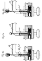
- a pusher device 17 * which over the nut 11 * with the closing and opening mechanism 9 * is operatively connected.
- the pusher device 17 * comprises a pusher 19 *, in which an activation unit 21 * is integrated, which is formed in the present embodiment as a push rod 22 *.
- the push rod 22 * protrudes with a first end 23 * out of the pusher 19 *, so that this free end 23 * can be used as a push button, which can be actuated eg by means of thumbs.
- a blocking device 27 * At an opposite second end 24 *.
- Blockierlement 28 * a blocking pin 36 *, which is connected to the activation unit 21 * and the push rod 22 *, and a recess 38 * in the lock housing 7 *, in which the blocking pin 36 * in the in Fig. 3b engages shown first operating state.
- the activation unit 21 * or the push rod 22 * is biased by an activation spring 37 * in the direction of the first free end 23 * (push button), so that the blocking pin 36 * is fixed in the recess 38 *.
- the push rod 22 is connected via a locking device 25 * in the in Fig. 3b Locked position shown.
- the unlocking is carried out as in the first embodiment by pressing and then rotating the activation unit 21 and the push rod 22.
- the nut 11 * can then be rotated manually, so that the in Fig. 4a illustrated opening position and thus the second operating state is achieved.
- Fig. 4a corresponds to Fig. 2a ,
- FIGS. 5a. 5b and 5c In each case, a variant of the locking device 25 is shown for the first embodiment, which of course also for other embodiments and in particular for the second embodiment can be used.
- Fig. 5a shows the locking device 25 as a screw clamp.
- a screw 39 is from the outside through the pusher device 17 and the pusher 19 through in the Actuating unit 21 and the push rod 22 screwed and clamped this easily, so that a frictional engagement between the activation unit 21 and push rod 22 and pusher device 17 and pusher 19 is formed.
- Fig. 5b shows the locking device 25 as a bayonet coil.
- the pressing is omitted before turning. It then has to be turned exclusively to get from the first operating state to the second operating state and back again.
- Fig. 5c shows the locking device 25 as a bayonet lever. This corresponds to the construction of the locking device 25, 25 * described above for the first and second embodiments.
Description
- Die vorliegende Erfindung betrifft eine Schließvorrichtung mit einer in einem Schlossgehäuse integrierten Schließ- und Öffnungsmechanik, wobei die Schließ- und Öffnungsmechanik in einem ersten Betriebszustand in einer Schließstellung blockiert ist und sich in einem zweiten Betriebszustand in einer Öffnungsstellung befindet, und mit einer Drückereinrichtung zum Betätigen der Schließ- und Öffnungsmechanik im zweiten Betriebszustand, die über eine Nuss mit der Schließ- und Öffnungsmechanik wirkverbunden ist.
- Eine solche Schließvorrichtung ist aus dem Stand der Technik allgemein bekannt. Regelmäßig wird z.B. eine Tür mit einer solchen Schließvorrichtung abgeschlossen, wobei der Drücker dann beweglich bleibt. Es gibt Schließsysteme, bei denen in der Schließstellung einer Schließvorrichtung der Drücker blockiert ist. Solche Schließsysteme sind z.B. aus
US0159486 oder ausAT357431 - Die Aufgabe der vorliegenden Erfindung ist, eine Schließvorrichtung der eingangs genannten Art derart weiterzubilden, dass eine verriegelte Tür mit blockiertem Drücker manuell geöffnet werden kann.
- Die Aufgabe wird erfindungsgemäß dadurch gelöst, dass die Drückereinrichtung eine Aktivierungseinheit aufweist, welche bei manueller Betätigung durch einen Benutzer die durch den elektromagnetischen Türöffner erzielte Blockade der Schließ- und Öffnungsmechanik im ersten Betriebszustand aufhebt und dadurch den zweiten Betriebszustand der Öffnungsstellung herbeiführt.
- Mit der erfindungsgemäßen Schließvorrichtung kann der Benutzer von innen eine automatisch verriegelte Tür ohne Panik wieder manuell öffnen. Erfindungsgemäß wirkt die Aktivierungseinheit mit einer Blockiereinrichtung zusammen, welche die Nuss im ersten Betriebszustand gegen eine Drehung blockiert und im zweiten Betriebszustand freigibt. Durch diese Konstruktion ist es möglich, auf einfache Weise auf die Drehung der Nuss Einfluss zu nehmen. Über die Drehbarkeit der Nuss wird in der Schließ- und Öffnungsmechanik bewirkt, dass sich z.B. ein Fallenelement und/oder einer Riegelelement aus eine Schließstellung zurückziehen kann/können. Wenn sich also diese Bauteile in einer Schließstellung befinden, führt die Blockade der Nuss auch zu einer Blockade des Riegelelements und/oder Fallenelements. Erfindungsgemäß umfasst die Blockiereinrichtung ein Blockierelement, das sich in dem ersten Betriebszustand wenigstens teilweise in der Bewegungsbahn der Druckstange befindet und im zweiten Betriebszustand von der Druckstange aus der Bewegungsbahn herausgedrückt ist. Dadurch wird die Wirkung der Druckstange als "Speerspitze" optimiert.
- Ein weiterer Vorteil der vorliegenden Erfindung ist, dass die Blockiereinrichtung quer zur Aktivierungseinheit angeordnet ist. Dadurch ist es möglich, die Aktion der Aktivierungseinheit von einer Seite aus mithilfe der Blockiereinrichtung zu unterbinden. Ein weiterer Vorteil ist, dass die Aktivierungseinheit eine Druckstange umfasst, die sich bei Betätigung der Aktivierungseinheit auf einer Bewegungsbahn bewegt. Eine solche Druckstange kann in einem an sich üblichen Drücker integriert werden. Dadurch kann die Druckstange als "Speerspitze" verwendet werden, um den Weg freizumachen, derart, dass sich die Nuss drehen kann.
- Ein weiterer Vorteil ist auch, dass das Blockierelement in Richtung der Bewegungsbahn der Druckstange vorgespannt ist. Dadurch ist sichergestellt, dass sich das Blockierelement beim automatischen Betriebe immer sicher im ersten Betriebszustand befindet und nur durch eine manuelle Einwirkung gegen die Vorspannung aus diesem sicheren ersten Betriebszustand herausgebracht werden kann.
- In einer ersten Ausführungsform ist es von Vorteil, dass das Blockierelement eine Kugelreihe aus mehreren, aneinander anstoßenden Kugeln ist, die in einem Federgehäuse geführt ist, wobei im ersten Betriebszustand eine Kugel mit ihrem halben Kugeldurchmesser in der Bewegungsbahn der Druckstange liegt und im zweiten Betriebszustand in das Federgehäuse zurückgedrückt ist. Dadurch kann mit geringem Kraftaufwand und geringem mechanischen Aufwand eine wirksame Entsperrung der Nuss erfolgen.
- In einer zweiten Ausführungsform ist es von Vorteil, dass das Blockierlement ein Blockierstift ist, der sich in dem ersten Betriebszustand in die Bewegungsbahn der Druckstange erstreckt, und im zweiten Betriebszustand aus der Bewegungsbahn herausgedreht ist.
- Diese Konstruktion ist auch ganz wirkungsvoll und stellt eine praktische Alternative zur Kugellösung dar.
- Weitere Vorteile der vorliegenden Erfindung ergeben sich aus den Merkmalen der weiteren Unteransprüche.
- Ausführungsformen der vorliegenden Erfindung werden im Folgenden anhand der Zeichnung näher beschrieben. Es zeigen:
- Fig. 1a
- eine schematische Darstellung einer Schließvorrichtung gemäß einer ersten Ausführungsform der vorliegenden Erfindung im verriegelten Zustand, in der wichtige Bauteile fett wiedergegeben sind;
- Fig. 1b
- eine schematische Darstellung einer Drückereinrichtung für die Schließvorrichtung in der Situation aus
Fig. 1a ; - Fig. 2a
- eine schematische Darstellung der Schließvorrichtung aus
Fig. 1a im entriegelten Zustand, in der wichtige Bauteile fett wiedergegeben sind; - Fig. 2b
- eine schematische Darstellung einer Drückereinrichtung für die Schließvorrichtung in der Situation aus
Fig. 2a ; - Fig. 3a
- eine schematische Darstellung einer Schließvorrichtung gemäß einer zweiten Ausführungsform der vorliegenden Erfindung im verriegelten Zustand, in der wichtige Bauteile fett wiedergegeben sind;
- Fig. 3b
- eine schematische Darstellung einer Drückereinrichtung für die Schließvorrichtung in der Situation aus
Fig. 3a ; - Fig. 4a
- eine schematische Darstellung der Schließvorrichtung aus
Fig. 3a im entriegelten Zustand, in der wichtige Bauteile fett wiedergegeben sind; - Fig. 4b
- eine schematische Darstellung einer Drückereinrichtung für die Schließvorrichtung in der Situation aus
Fig. 4a ; - Fig. 5a
- eine schematische Darstellung der Drückereinrichtung mit einer ersten Variante einer Druckstangenverriegelung;
- Fig. 5b
- eine schematische Darstellung der Drückereinrichtung mit einer zweiten Variante einer Druckstangenverriegelung; und
- Fig. 5c
- eine schematische Darstellung der Drückereinrichtung mit einer dritten Variante einer Druckstangenverriegelung.
- In
Fig. 1a ist schematische eine erste Ausführungsform einer Schließvorrichtung 1 dargestellt, die dazu vorgesehen ist, in eine Tür (nicht dargestellt) eingebaut zu werden, so dass ein Riegelelement 3 und oder ein Fallenelement 5 über eine Stulpschiene 6 vorstehen und in angepasste Öffnungen (nicht dargestellt) eines Schließblechs (nicht dargestellt) eingreifen können. Die Schließvorrichtung 1 umfasst ein Schlossgehäuse 7, in dem eine Schließ- und Öffnungsmechanik 9 angeordnet ist. Diese Schließ- und Öffnungsmechanik 9 ist an sich bekannt und nicht Gegenstand der vorliegenden Erfindung. Für die Erfindung von Bedeutung ist nur eine Nuss 11, die drehbar (rechts/links in der Draufsicht ausFig. 1a ) gelagert ist und mit einem Hebel 13 verbunden ist, der mit dem Fallenelement 5 zusammenwirkt, und das von der Schließ- und Öffnungsmechanik 9 auslösbare Riegelelement 3. In der inFig. 1a dargestellten Situation hält der Hebel 13 das Fallenelement 5 gegen eine Federkraft in einer Schließstellung. Zudem lässt sich die Nuss 11 nicht drehen. Diese Schließstellung stellt im Sinne der vorliegenden Erfindung einen ersten Betriebszustand der Schließ- und Öffnungsmechanik 9 dar. - In
Fig. 1b ist schematisch eine Drückereinrichtung 17 dargestellt, die über die Nuss 11 mit der Schließ- und Öffnungsmechanik 9 wirkverbunden ist. Die Drückereinrichtung 17 umfasst einen Drücker 19, in dem eine Aktivierungseinheit 21 integriert ist, die in der vorliegenden Ausführungsform als Druckstange 22 ausgebildet ist. Die Druckstange 22 ragt mit einem ersten Ende 23 aus dem Drücker 19 heraus, so dass dieses freie Ende 23 als Druckknopf verwendet werden kann, der z.B. mittels Daumen betätigt werden kann. Ein entgegengesetztes zweites Ende 24 der Druckstange 22 ist konvex ausgebildet und ist in der dargestellten Ausführungsform eine Kugel. In anderen Ausführungsformen kann das konvexe Ende eine Halbkugel oder ein Teilstück einer Kugelfläche sein. - Die Druckstange 22 ist über eine Verriegelungseinrichtung 25 in der in
Fig. 1b dargestellten Position verriegelbar. Am zweiten Ende 24 befindet sich eine Blockiereinrichtung 27 mit einem Blockierlement 28. Diese umfasst in der vorliegenden Ausführungsform einen Federkanal 29, der quer zur Aktivierungseinheit 21 und in der vorliegenden Ausführungsform somit auch quer zur Druckstange 22 verläuft. Der Federkanal 29 erstreckt sich durch ein sich an die Nuss 11 angrenzendes Federgehäuse 30 und durch eine Wand der Nuss 11 hindurch, bis in die Nussöffnung hinein. In dem Federkanal 29 sind als Blockierelement 28 mehrere Kugeln 31 lose angeordnet, die durch eine Feder 33 am Federkanalboden 35 in Richtung Nussöffnung vorgespannt sind, derart, dass genau eine Kugel 31 mit ungefähr ihrem größten Durchmesser auf der Grenze zwischen Federgehäuse 30 und der Wand der Nuss 11 liegt. Aufgrund der Sperrung durch das konvexe zweite Ende 24 bilden die Kugeln 31 eine kinematische Kette, wirken also wie ein durchgehender Stab und blockieren die Nuss 11 in der inFig. 1a und Fig. 1b jeweils dargestellten Position. - Durch eine Betätigung der Druckstange 22 durch Drücken auf das erste Ende 23 wird die in
Fig. 2b dargestellt Freigabeposition erreicht, so dass die Schließ- und Öffnungsmechanik9 durch ein Drehen der Nuss 11 mittels Drückereinrichtung 17, wie inFig. 1a gezeigt, betätigt und eine Öffnungsstellung erreicht wird, in welcher das Riegelelement 3 und das Fallenelement 5 in das Schlossgehäuse 7 zurückgezogen sind. Das stellt im Sinne der vorliegenden Erfindung einen zweiten Betriebszustand der Schließ- und Öffnungsmechanik 9 dar. Das konvexe zweite Ende 24 drückt gegen die erste der Kugeln 31 im Federkanal 29 und drückt die ganze Kugelkette gegen die Federkraft der Feder 33 in Richtung Feder 33, so weit, bis sich die Kugel 31, welche mit ungefähr ihrem größten Durchmesser genau auf der Grenze zwischen Federgehäuse 30 und Wand der Nuss 11 gelegen hat, nun in das Federgehäuse 30 verschoben ist, so dass sich nun eine Grenzfläche zwischen zwei Kugeln 31 genau auf der Grenze zwischen Federgehäuse 30 und Wand der Nuss 11 befindet. In dieser Position der Aktivierungseinheit 21 und in der vorliegenden Ausführungsform der Druckstange 22 lässt sich dieses/diese gegen den Uhrzeigersinn drehen (Pfeil inFig. 2b ) und dadurch an der Verriegelungseinrichtung 25 verriegeln. Aufgrund der geringen Kraftwirkung an der vorgenannten Grenzfläche zwischen den beiden Kugeln 31 lässt sich die Nuss 11 nun drehen, so dass eine manuelle Öffnung mittels der Drückereinrichtung 17 bzw. mittels Drücker 19 möglich ist. - Die Verriegelungseinrichtung 25 umfasst in der vorliegenden Ausführungsform einen Riegelstift 25.1, der in etwa senkrecht an der Aktivierungseinheit 21 bzw. der Druckstange 22 angebracht ist und durch eine L-förmige Ausnehmung 25.2 vorsteht, die als Riegelstiftführung dient. In dem in
Fig. 1b dargestellten ersten Betriebszustand befindet sich der Riegelstift 25.1 an einem von der Nuss 11 entfernteren Ende 25.3 der L-förmigen Ausnehmung und in dem inFig. 2b dargestellten zweiten Betriebszustand befindet sich der Riegelstift 25.1 an einer der Nuss 11 näheren Mittellage in der L-förmigen Ausnehmung 25.2 und in einer in diesem zweiten Betriebszustand verriegelten Position, also nach einer Drehung der Aktivierungseinheit 21 bzw. Druckstange 22, befindet sich der Riegelstift 25.1 an einem der Nuss 11 näheren Ende 25. 4 der L-förmigen Ausnehmung 25.2. Die Aktivierungseinheit 21 bzw. die Druckstange 22 ist von der Nuss 11 weg in Richtung des ersten Endes 23 vorgespannt. - Die Aktivierungseinheit 21 und auch die Druckstange 22 können auch mehrteilig und dann auch in unterschiedlichen Materialien ausgebildet sein.
- In den
Figuren 3a, 3b, 4a und 4b ist eine zweite Ausführungsform der vorliegenden Erfindung dargestellt. Die grundlegende Konstruktion ist mit derjenigen der ersten Ausführungsform identisch. Unterschiedlich ist die Ausgestaltung der Blockiereinrichtung. Für die Beschreibung der zweiten Ausführungsform wird auf die Beschreibung der ersten Ausführungsform ausdrücklich Bezug genommen. Aus Gründen der Klarheit erhalten die im Rahmen der Beschreibung der zweiten Ausführungsform genannten Bauteile die gleichen Bezugszeichen mit einem "*", auch dann, wenn sie sich baulich nicht von denen der ersten Ausführungsform unterscheiden. - In
Fig. 3b ist schematisch eine Drückereinrichtung 17* dargestellt, die über die Nuss 11* mit der Schließ- und Öffnungsmechanik 9* wirkverbunden ist. Die Drückereinrichtung 17* umfasst einen Drücker 19*, in dem eine Aktivierungseinheit 21* integriert ist, die in der vorliegenden Ausführungsform als Druckstange 22* ausgebildet ist. Die Druckstange 22* ragt mit einem ersten Ende 23* aus dem Drücker 19* heraus, so dass dieses freie Ende 23* als Druckknopf verwendet werden kann, der z.B. mittels Daumen betätigt werden kann. An einem entgegengesetzten zweiten Ende 24* befindet sich eine Blockiereinrichtung 27*. Diese umfasst als Blockierlement 28* einen Blockierstift 36*, der mit der Aktivierungseinheit 21* bzw. mit der Druckstange 22* verbunden ist, und eine Aussparung 38* im Schlossgehäuse 7*, in welche der Blockierstift 36* in dem inFig. 3b dargestellten ersten Betriebszustand eingreift. Die Aktivierungseinheit 21* bzw. die Druckstange 22* ist durch eine Aktivierungsfeder 37* in Richtung des ersten freien Endes 23* (Druckknopf) vorgespannt, so dass der Blockierstift 36* fest in der Aussparung 38* liegt. - Die Druckstange 22 ist über eine Verriegelungseinrichtung 25* in der in
Fig. 3b dargestellten Position verriegelbar. Die Entriegelung erfolgt wie in der ersten Ausführungsform durch ein Drücken und anschließendes Drehen der Aktivierungseinheit 21 bzw. der Druckstange 22.Die Nuss 11* lässt sich dann manuell drehen, so dass die inFig. 4a dargestellte Öffnungsstellung und somit der zweite Betriebszustand erreicht wird.Fig. 4a entsprichtFig. 2a . - In den
Figuren 5a. 5b und 5c ist jeweils eine Variante der Verriegelungseinrichtung 25 für die erste Ausführungsform dargestellt, die jeweils natürlich auch für andere Ausführungsformen und insbesondere auch für die zweite Ausführungsform verwendet werden können. -
Fig. 5a zeigt die Verriegelungseinrichtung 25 als Schraubenklemmung. Eine Schraube 39 wird von außen durch die Drückereinrichtung 17 bzw. den Drücker 19 hindurch in die Aktivierungseinheit 21 bzw. die Druckstange 22 geschraubt und klemmt diese leicht, so dass ein Reibschluss zwischen Aktivierungseinheit 21 bzw. Druckstange 22 und Drückereinrichtung 17 bzw. Drücker 19 entsteht. -
Fig. 5b zeigt die Verriegelungseinrichtung 25 als Bajonetwendel. In dieser Variante entfällt das Drücken vor dem Drehen. Es muss dann ausschließlich gedreht werden, um von dem ersten Betriebszustand in den zweiten Betriebszustand und wieder zurück zu gelangen.Fig. 5c zeigt die Verriegelungseinrichtung 25 als Bajonethebel. Dies entspricht der Bauweise der vorstehend zur ersten und zweiten Ausführungsform beschriebenen Verriegelungseinrichtung 25, 25*. -
- 1
- Schließvorrichtung
- 3
- Riegelelement
- 5
- Fallenelement
- 7
- Schlossgehäuse
- 9
- Schließ- und Öffnungsmechanik
- 9*
- Schließ- und Öffnungsmechanik
- 11
- Nuss
- 11*
- Nuss
- 13
- Hebel
- 17
- Drückereinrichtung
- 17*
- Drückereinrichtung
- 19
- Drücker
- 19*
- Drücker
- 21
- Aktivierungseinheit
- 21*
- Aktivierungseinheit
- 22
- Druckstange
- 22*
- Druckstange
- 23
- erstes Ende
- 24
- zweites Ende
- 24*
- zweites Ende
- 25
- Verriegelungseinrichtung nicht angezogen
- 25*
- Verriegelungseinrichtung
- 25.1
- Riegelstift
- 25.2
- L-förmige Ausnehmung
- 25.3
- entfernteres Ende
- 25.4
- näheres Ende
- 25*
- Riegelstift
- 27
- Blockiereinrichtung
- 27*
- Blockiereinrichtung
- 28
- Blockierelement
- 28*
- Blockierelement
- 29
- Federkanal
- 30
- Federgehäuse
- 31
- Kugeln
- 33
- Feder
- 35
- Federkanalboden
- 36*
- Blockierstift
- 37*
- Aktivierungsfeder
- 38*
- Aussparung
- 39
- Schraube
Claims (9)
- Schließvorrichtung (1) mit einer in einem Schlossgehäuse (7) integrierten Schließ- und Öffnungsmechanik (9; 9*), die mittels eines elektromagnetischen Türöffners automatisch betätigt wird, wobei die Schließ- und Öffnungsmechanik (9; 9*) in einem ersten Betriebszustand in einer Schließstellung blockiert ist und sich in einem zweiten Betriebszustand in einer Öffnungsstellung befindet, und mit einer Drückereinrichtung (17) zum Betätigen der Schließ- und Öffnungsmechanik (9; 9*) im zweiten Betriebszustand, die über eine Nuss (11; 11*) mit der Schließ- und Öffnungsmechanik (9) wirkverbunden ist, wobei die Drückereinrichtung (17; 17*) eine Aktivierungseinheit (21; 21*; 22; 22*) aufweist, welche bei manueller Betätigung durch einen Benutzer die durch den elektromagnetischen Türöffner erzielte Blockade der Schließ- und Öffnungsmechanik (9) im ersten Betriebsszustand aufhebt und dadurch den zweiten Betriebszustand der Öffnungsstellung herbeiführt, wobei die Aktivierungseinheit(21; 21*; 22; 22*) mit einer Blockiereinrichtung (27; 27*) zusammenwirkt, welche die Nuss (11) im ersten Betriebszustand gegen eine Drehung blockiert und im zweiten Betriebszustand freigibt.
dadurch gekennzeichnet,
dass die Blockiereinrichtung (27; 27*) ein Blockierelement (28; 28*) umfasst, das sich in dem ersten Betriebszustand wenigstens teilweise in der Bewegungsbahn der Aktivierungseinheit (21; 21*; 22; 22*) befindet und im zweiten Betriebszustand von der Aktivierungseinheit (21; 21*; 22; 22*) aus der Bewegungsbahn herausgedrückt ist. - Schließvorrichtung nach Anspruch 1,
dadurch gekennzeichnet,
dass die Blockiereinrichtung (27; 27*) quer zur Aktivierungseinheit (21; 21*; 22; 22*) angeordnet ist. - Schließvorrichtung nach Anspruch 1 oder 2,
dadurch gekennzeichnet,
dass die Aktivierungseinheit (21; 21*; 22; 22*) eine Druckstange (22; 22*) umfasst, die sich bei Betätigung der Aktivierungseinheit (21; 21*; 22; 22*) auf einer Bewegungsbahn bewegt. - Schließvorrichtung nach einem der Ansprüche 1 bis 3,
dadurch gekennzeichnet,
dass das Blockierelement (28) in Richtung einer Nussöffnung vorgespannt ist. - Schließvorrichtung nach einem der Ansprüche 1 bis 4,
dadurch gekennzeichnet,
dass das Blockierelement (28) aus einer Reihe von Kugeln (31) gebildet ist, die eine kinematische Kette bilden und in einem Federkanal (29) geführt sind, der teilweise in einem Federgehäuse (30) und in der Nuss (11) ausgebildet ist, wobei im ersten Betriebszustand eine Kugel (31) mit ihrem größten Kugeldurchmesser auf einer Grenze zwischen Federgehäuse (30) und Nuss (11) liegt und im zweiten Betriebszustand eine Grenzfläche zwischen zwei aneinander anstoßenden Kugeln (31) auf der Grenze zwischen Federgehäuse (30) und Nuss (11) liegt. - Schließvorrichtung nach einem der Ansprüche 1 bis 3,
dadurch gekennzeichnet,
dass das Blockierlement (28*) ein Blockierstift (36*) ist, der in dem ersten Betriebszustand in eine Aussparung (38*) im Schlossgehäuse (7*) eingreift und sich in die Bewegungsbahn der Aktivierungseinheit (21; 21*; 22; 22*) erstreckt, und im zweiten Betriebszustand aus der Aussparung (38*) herausgedreht ist. - Schließvorrichtung nach Anspruch 6,
dadurch gekennzeichnet,
dass die Aktivierungseinheit (21*; 22*) in Richtung eines ersten freien Endes (23*) vorgespannt ist. - Schließvorrichtung nach einem der vorstehenden Ansprüche,
dadurch gekennzeichnet,
dass die Aktivierungseinheit (21; 21*; 22; 22*) mit einer Verriegelungseinrichtung (25; 25*) versehen ist. - Schließvorrichtung nach Anspruch 8,
dadurch gekennzeichnet,
dass die Verriegelungseinrichtung (25; 25*) einen Riegelstift (25.1) und eine L-förmige Ausnehmung (25.2) umfasst, wobei der Riegelstift (25.1) an der Aktivierungseinheit (21; 21*; 22; 22*) ausgebildet ist und die L-förmige Ausnehmung (25.2) an der Drückereinrichtung (17; 17*) ausgebildet ist.
Priority Applications (1)
| Application Number | Priority Date | Filing Date | Title |
|---|---|---|---|
| PL15003581T PL3101202T3 (pl) | 2015-01-16 | 2015-12-16 | Urządzenie zamykające z funkcją antypaniczną |
Applications Claiming Priority (1)
| Application Number | Priority Date | Filing Date | Title |
|---|---|---|---|
| DE201520000396 DE202015000396U1 (de) | 2015-01-16 | 2015-01-16 | Schließvorrichtung mit Panikschaltung |
Publications (2)
| Publication Number | Publication Date |
|---|---|
| EP3101202A1 EP3101202A1 (de) | 2016-12-07 |
| EP3101202B1 true EP3101202B1 (de) | 2018-07-04 |
Family
ID=52830048
Family Applications (1)
| Application Number | Title | Priority Date | Filing Date |
|---|---|---|---|
| EP15003581.4A Active EP3101202B1 (de) | 2015-01-16 | 2015-12-16 | Schliessvorrichtung mit panikschaltung |
Country Status (5)
| Country | Link |
|---|---|
| EP (1) | EP3101202B1 (de) |
| DE (1) | DE202015000396U1 (de) |
| ES (1) | ES2689727T3 (de) |
| PL (1) | PL3101202T3 (de) |
| TR (1) | TR201814252T4 (de) |
Family Cites Families (6)
| Publication number | Priority date | Publication date | Assignee | Title |
|---|---|---|---|---|
| US159486A (en) * | 1875-02-02 | Improvement in door-knob fastenings | ||
| US2070149A (en) * | 1934-05-17 | 1937-02-09 | Turner John | Door lock |
| JPS5929098Y2 (ja) * | 1976-08-24 | 1984-08-21 | ワイケイケイ株式会社 | ドアハンドル |
| AT357431B (de) * | 1978-11-27 | 1980-07-10 | Wasserfaller G | Tuerschloss |
| GB2183284A (en) * | 1985-11-22 | 1987-06-03 | David George Whitworth | Window closure device |
| DE8704432U1 (de) * | 1987-03-25 | 1988-07-21 | Wehag Leichtmetall Gmbh, 5628 Heiligenhaus, De |
-
2015
- 2015-01-16 DE DE201520000396 patent/DE202015000396U1/de not_active Expired - Lifetime
- 2015-12-16 TR TR2018/14252T patent/TR201814252T4/tr unknown
- 2015-12-16 PL PL15003581T patent/PL3101202T3/pl unknown
- 2015-12-16 ES ES15003581.4T patent/ES2689727T3/es active Active
- 2015-12-16 EP EP15003581.4A patent/EP3101202B1/de active Active
Non-Patent Citations (1)
| Title |
|---|
| None * |
Also Published As
| Publication number | Publication date |
|---|---|
| DE202015000396U1 (de) | 2015-03-27 |
| ES2689727T3 (es) | 2018-11-15 |
| EP3101202A1 (de) | 2016-12-07 |
| TR201814252T4 (tr) | 2018-11-21 |
| PL3101202T3 (pl) | 2019-02-28 |
Similar Documents
| Publication | Publication Date | Title |
|---|---|---|
| EP3109384B1 (de) | Schliessvorrichtung mit starker riegeldruckfeder | |
| DE102007012613B4 (de) | Panikschloss | |
| EP1970505A2 (de) | Panikschloss | |
| DE102013220382A1 (de) | Kraftfahrzeugtürverschluss | |
| DE102012111881B4 (de) | Motorisch betreibbares Standflügelschloss mit Riegel- und Fallenauswerfer | |
| DE102012108242A1 (de) | Schloss für eine Tür | |
| EP2666938B1 (de) | Schloss für eine tür | |
| EP3101202B1 (de) | Schliessvorrichtung mit panikschaltung | |
| EP3026201A1 (de) | Zusatzverriegelung | |
| EP3628801B1 (de) | Schlossvorrichtung für eine tür und verfahren zum öffnen einer tür | |
| EP3112564A1 (de) | Selbstverriegelndes fallenschloss | |
| DE102013013547B4 (de) | Schloss mit Riegel mit Entriegelungspin | |
| EP3216952B1 (de) | Verriegelungseinrichtung | |
| DE2313611A1 (de) | Tuerschloss | |
| DE102013106142A1 (de) | Schloss für eine Tür mit einem Schlossgehäuse | |
| DE102017000346B4 (de) | Schloss mit Fallensperre | |
| DE849056C (de) | Selbstschliessendes Fallriegelschloss mit automatischer Verschluss-sperrung, insbesondere fuer Autobus- und Waggontueren | |
| DE102015100381B4 (de) | Schwenkhebelverschluss mit einer Sperreinrichtung für das Verriegelungsteil | |
| DE202014002240U1 (de) | Einsteckschloss für eine Tür, ein Fenster oder dergleichen | |
| AT516516B1 (de) | Schloss | |
| WO2015010670A1 (de) | Schliessvorrichtung mit notöffnung | |
| DE102014000724A1 (de) | Hubbett für Land-, Wasser- und Luftfahrzeuge mit Betätigungseinrichtung | |
| DE313911C (de) | ||
| DE1553430C (de) | Verschlußeinrichtung an Geldschrank und Tresorturen od dgl | |
| EP3569801A1 (de) | Schloss, insbesondere panikschloss |
Legal Events
| Date | Code | Title | Description |
|---|---|---|---|
| PUAI | Public reference made under article 153(3) epc to a published international application that has entered the european phase |
Free format text: ORIGINAL CODE: 0009012 |
|
| AK | Designated contracting states |
Kind code of ref document: A1 Designated state(s): AL AT BE BG CH CY CZ DE DK EE ES FI FR GB GR HR HU IE IS IT LI LT LU LV MC MK MT NL NO PL PT RO RS SE SI SK SM TR |
|
| AX | Request for extension of the european patent |
Extension state: BA ME |
|
| 17P | Request for examination filed |
Effective date: 20170606 |
|
| RBV | Designated contracting states (corrected) |
Designated state(s): AL AT BE BG CH CY CZ DE DK EE ES FI FR GB GR HR HU IE IS IT LI LT LU LV MC MK MT NL NO PL PT RO RS SE SI SK SM TR |
|
| RIC1 | Information provided on ipc code assigned before grant |
Ipc: E05B 65/10 20060101ALN20171130BHEP Ipc: E05B 13/10 20060101ALI20171130BHEP Ipc: E05B 13/00 20060101AFI20171130BHEP |
|
| GRAP | Despatch of communication of intention to grant a patent |
Free format text: ORIGINAL CODE: EPIDOSNIGR1 |
|
| INTG | Intention to grant announced |
Effective date: 20180124 |
|
| GRAS | Grant fee paid |
Free format text: ORIGINAL CODE: EPIDOSNIGR3 |
|
| GRAA | (expected) grant |
Free format text: ORIGINAL CODE: 0009210 |
|
| AK | Designated contracting states |
Kind code of ref document: B1 Designated state(s): AL AT BE BG CH CY CZ DE DK EE ES FI FR GB GR HR HU IE IS IT LI LT LU LV MC MK MT NL NO PL PT RO RS SE SI SK SM TR |
|
| REG | Reference to a national code |
Ref country code: GB Ref legal event code: FG4D Free format text: NOT ENGLISH |
|
| REG | Reference to a national code |
Ref country code: CH Ref legal event code: EP |
|
| REG | Reference to a national code |
Ref country code: AT Ref legal event code: REF Ref document number: 1014675 Country of ref document: AT Kind code of ref document: T Effective date: 20180715 |
|
| REG | Reference to a national code |
Ref country code: IE Ref legal event code: FG4D Free format text: LANGUAGE OF EP DOCUMENT: GERMAN |
|
| REG | Reference to a national code |
Ref country code: DE Ref legal event code: R096 Ref document number: 502015004889 Country of ref document: DE |
|
| REG | Reference to a national code |
Ref country code: NL Ref legal event code: MP Effective date: 20180704 |
|
| REG | Reference to a national code |
Ref country code: ES Ref legal event code: FG2A Ref document number: 2689727 Country of ref document: ES Kind code of ref document: T3 Effective date: 20181115 |
|
| REG | Reference to a national code |
Ref country code: LT Ref legal event code: MG4D |
|
| PG25 | Lapsed in a contracting state [announced via postgrant information from national office to epo] |
Ref country code: NL Free format text: LAPSE BECAUSE OF FAILURE TO SUBMIT A TRANSLATION OF THE DESCRIPTION OR TO PAY THE FEE WITHIN THE PRESCRIBED TIME-LIMIT Effective date: 20180704 |
|
| PG25 | Lapsed in a contracting state [announced via postgrant information from national office to epo] |
Ref country code: CZ Free format text: LAPSE BECAUSE OF FAILURE TO SUBMIT A TRANSLATION OF THE DESCRIPTION OR TO PAY THE FEE WITHIN THE PRESCRIBED TIME-LIMIT Effective date: 20180704 Ref country code: FI Free format text: LAPSE BECAUSE OF FAILURE TO SUBMIT A TRANSLATION OF THE DESCRIPTION OR TO PAY THE FEE WITHIN THE PRESCRIBED TIME-LIMIT Effective date: 20180704 Ref country code: SE Free format text: LAPSE BECAUSE OF FAILURE TO SUBMIT A TRANSLATION OF THE DESCRIPTION OR TO PAY THE FEE WITHIN THE PRESCRIBED TIME-LIMIT Effective date: 20180704 Ref country code: LT Free format text: LAPSE BECAUSE OF FAILURE TO SUBMIT A TRANSLATION OF THE DESCRIPTION OR TO PAY THE FEE WITHIN THE PRESCRIBED TIME-LIMIT Effective date: 20180704 Ref country code: IS Free format text: LAPSE BECAUSE OF FAILURE TO SUBMIT A TRANSLATION OF THE DESCRIPTION OR TO PAY THE FEE WITHIN THE PRESCRIBED TIME-LIMIT Effective date: 20181104 Ref country code: RS Free format text: LAPSE BECAUSE OF FAILURE TO SUBMIT A TRANSLATION OF THE DESCRIPTION OR TO PAY THE FEE WITHIN THE PRESCRIBED TIME-LIMIT Effective date: 20180704 Ref country code: NO Free format text: LAPSE BECAUSE OF FAILURE TO SUBMIT A TRANSLATION OF THE DESCRIPTION OR TO PAY THE FEE WITHIN THE PRESCRIBED TIME-LIMIT Effective date: 20181004 Ref country code: GR Free format text: LAPSE BECAUSE OF FAILURE TO SUBMIT A TRANSLATION OF THE DESCRIPTION OR TO PAY THE FEE WITHIN THE PRESCRIBED TIME-LIMIT Effective date: 20181005 Ref country code: BG Free format text: LAPSE BECAUSE OF FAILURE TO SUBMIT A TRANSLATION OF THE DESCRIPTION OR TO PAY THE FEE WITHIN THE PRESCRIBED TIME-LIMIT Effective date: 20181004 |
|
| PG25 | Lapsed in a contracting state [announced via postgrant information from national office to epo] |
Ref country code: AL Free format text: LAPSE BECAUSE OF FAILURE TO SUBMIT A TRANSLATION OF THE DESCRIPTION OR TO PAY THE FEE WITHIN THE PRESCRIBED TIME-LIMIT Effective date: 20180704 Ref country code: HR Free format text: LAPSE BECAUSE OF FAILURE TO SUBMIT A TRANSLATION OF THE DESCRIPTION OR TO PAY THE FEE WITHIN THE PRESCRIBED TIME-LIMIT Effective date: 20180704 Ref country code: LV Free format text: LAPSE BECAUSE OF FAILURE TO SUBMIT A TRANSLATION OF THE DESCRIPTION OR TO PAY THE FEE WITHIN THE PRESCRIBED TIME-LIMIT Effective date: 20180704 |
|
| REG | Reference to a national code |
Ref country code: DE Ref legal event code: R097 Ref document number: 502015004889 Country of ref document: DE |
|
| PG25 | Lapsed in a contracting state [announced via postgrant information from national office to epo] |
Ref country code: EE Free format text: LAPSE BECAUSE OF FAILURE TO SUBMIT A TRANSLATION OF THE DESCRIPTION OR TO PAY THE FEE WITHIN THE PRESCRIBED TIME-LIMIT Effective date: 20180704 Ref country code: RO Free format text: LAPSE BECAUSE OF FAILURE TO SUBMIT A TRANSLATION OF THE DESCRIPTION OR TO PAY THE FEE WITHIN THE PRESCRIBED TIME-LIMIT Effective date: 20180704 |
|
| PLBE | No opposition filed within time limit |
Free format text: ORIGINAL CODE: 0009261 |
|
| STAA | Information on the status of an ep patent application or granted ep patent |
Free format text: STATUS: NO OPPOSITION FILED WITHIN TIME LIMIT |
|
| PG25 | Lapsed in a contracting state [announced via postgrant information from national office to epo] |
Ref country code: SM Free format text: LAPSE BECAUSE OF FAILURE TO SUBMIT A TRANSLATION OF THE DESCRIPTION OR TO PAY THE FEE WITHIN THE PRESCRIBED TIME-LIMIT Effective date: 20180704 Ref country code: DK Free format text: LAPSE BECAUSE OF FAILURE TO SUBMIT A TRANSLATION OF THE DESCRIPTION OR TO PAY THE FEE WITHIN THE PRESCRIBED TIME-LIMIT Effective date: 20180704 Ref country code: SK Free format text: LAPSE BECAUSE OF FAILURE TO SUBMIT A TRANSLATION OF THE DESCRIPTION OR TO PAY THE FEE WITHIN THE PRESCRIBED TIME-LIMIT Effective date: 20180704 |
|
| 26N | No opposition filed |
Effective date: 20190405 |
|
| PG25 | Lapsed in a contracting state [announced via postgrant information from national office to epo] |
Ref country code: SI Free format text: LAPSE BECAUSE OF FAILURE TO SUBMIT A TRANSLATION OF THE DESCRIPTION OR TO PAY THE FEE WITHIN THE PRESCRIBED TIME-LIMIT Effective date: 20180704 Ref country code: LU Free format text: LAPSE BECAUSE OF NON-PAYMENT OF DUE FEES Effective date: 20181216 Ref country code: MC Free format text: LAPSE BECAUSE OF FAILURE TO SUBMIT A TRANSLATION OF THE DESCRIPTION OR TO PAY THE FEE WITHIN THE PRESCRIBED TIME-LIMIT Effective date: 20180704 |
|
| REG | Reference to a national code |
Ref country code: IE Ref legal event code: MM4A |
|
| PG25 | Lapsed in a contracting state [announced via postgrant information from national office to epo] |
Ref country code: IE Free format text: LAPSE BECAUSE OF NON-PAYMENT OF DUE FEES Effective date: 20181216 |
|
| PG25 | Lapsed in a contracting state [announced via postgrant information from national office to epo] |
Ref country code: MT Free format text: LAPSE BECAUSE OF FAILURE TO SUBMIT A TRANSLATION OF THE DESCRIPTION OR TO PAY THE FEE WITHIN THE PRESCRIBED TIME-LIMIT Effective date: 20180704 |
|
| PG25 | Lapsed in a contracting state [announced via postgrant information from national office to epo] |
Ref country code: PT Free format text: LAPSE BECAUSE OF FAILURE TO SUBMIT A TRANSLATION OF THE DESCRIPTION OR TO PAY THE FEE WITHIN THE PRESCRIBED TIME-LIMIT Effective date: 20180704 |
|
| PG25 | Lapsed in a contracting state [announced via postgrant information from national office to epo] |
Ref country code: MK Free format text: LAPSE BECAUSE OF NON-PAYMENT OF DUE FEES Effective date: 20180704 Ref country code: CY Free format text: LAPSE BECAUSE OF FAILURE TO SUBMIT A TRANSLATION OF THE DESCRIPTION OR TO PAY THE FEE WITHIN THE PRESCRIBED TIME-LIMIT Effective date: 20180704 Ref country code: HU Free format text: LAPSE BECAUSE OF FAILURE TO SUBMIT A TRANSLATION OF THE DESCRIPTION OR TO PAY THE FEE WITHIN THE PRESCRIBED TIME-LIMIT; INVALID AB INITIO Effective date: 20151216 |
|
| PGFP | Annual fee paid to national office [announced via postgrant information from national office to epo] |
Ref country code: GB Payment date: 20221223 Year of fee payment: 8 Ref country code: FR Payment date: 20221222 Year of fee payment: 8 Ref country code: AT Payment date: 20221221 Year of fee payment: 8 |
|
| PGFP | Annual fee paid to national office [announced via postgrant information from national office to epo] |
Ref country code: PL Payment date: 20221208 Year of fee payment: 8 Ref country code: BE Payment date: 20221223 Year of fee payment: 8 |
|
| PGFP | Annual fee paid to national office [announced via postgrant information from national office to epo] |
Ref country code: TR Payment date: 20221215 Year of fee payment: 8 Ref country code: ES Payment date: 20230119 Year of fee payment: 8 Ref country code: CH Payment date: 20230104 Year of fee payment: 8 |
|
| PGFP | Annual fee paid to national office [announced via postgrant information from national office to epo] |
Ref country code: IT Payment date: 20221228 Year of fee payment: 8 Ref country code: DE Payment date: 20230131 Year of fee payment: 8 |
|
| PGFP | Annual fee paid to national office [announced via postgrant information from national office to epo] |
Ref country code: ES Payment date: 20240216 Year of fee payment: 9 |