EP3095070B1 - Détection thermique - Google Patents
Détection thermique Download PDFInfo
- Publication number
- EP3095070B1 EP3095070B1 EP14824493.2A EP14824493A EP3095070B1 EP 3095070 B1 EP3095070 B1 EP 3095070B1 EP 14824493 A EP14824493 A EP 14824493A EP 3095070 B1 EP3095070 B1 EP 3095070B1
- Authority
- EP
- European Patent Office
- Prior art keywords
- temperature
- temperature sensor
- control module
- thermopile array
- sensing region
- Prior art date
- Legal status (The legal status is an assumption and is not a legal conclusion. Google has not performed a legal analysis and makes no representation as to the accuracy of the status listed.)
- Not-in-force
Links
- 238000005286 illumination Methods 0.000 claims description 36
- XLYOFNOQVPJJNP-UHFFFAOYSA-N water Substances O XLYOFNOQVPJJNP-UHFFFAOYSA-N 0.000 claims description 26
- 238000001514 detection method Methods 0.000 claims description 21
- 230000007613 environmental effect Effects 0.000 claims description 13
- 238000010521 absorption reaction Methods 0.000 claims description 7
- 230000035945 sensitivity Effects 0.000 claims description 7
- 238000004590 computer program Methods 0.000 claims description 5
- 239000002352 surface water Substances 0.000 claims description 2
- 230000007423 decrease Effects 0.000 description 8
- 238000012544 monitoring process Methods 0.000 description 5
- 230000005855 radiation Effects 0.000 description 4
- 239000010426 asphalt Substances 0.000 description 3
- 230000001419 dependent effect Effects 0.000 description 2
- 238000010586 diagram Methods 0.000 description 2
- 230000000694 effects Effects 0.000 description 2
- 238000005265 energy consumption Methods 0.000 description 2
- 238000012545 processing Methods 0.000 description 2
- 230000004044 response Effects 0.000 description 2
- XUIMIQQOPSSXEZ-UHFFFAOYSA-N Silicon Chemical compound [Si] XUIMIQQOPSSXEZ-UHFFFAOYSA-N 0.000 description 1
- 238000013459 approach Methods 0.000 description 1
- 238000009529 body temperature measurement Methods 0.000 description 1
- 238000001816 cooling Methods 0.000 description 1
- 238000005516 engineering process Methods 0.000 description 1
- 238000002474 experimental method Methods 0.000 description 1
- 230000006870 function Effects 0.000 description 1
- 238000010438 heat treatment Methods 0.000 description 1
- 238000009434 installation Methods 0.000 description 1
- 238000013507 mapping Methods 0.000 description 1
- 239000000463 material Substances 0.000 description 1
- 230000003287 optical effect Effects 0.000 description 1
- 238000005375 photometry Methods 0.000 description 1
- 239000004576 sand Substances 0.000 description 1
- 229910052710 silicon Inorganic materials 0.000 description 1
- 239000010703 silicon Substances 0.000 description 1
Images


Classifications
-
- H—ELECTRICITY
- H05—ELECTRIC TECHNIQUES NOT OTHERWISE PROVIDED FOR
- H05B—ELECTRIC HEATING; ELECTRIC LIGHT SOURCES NOT OTHERWISE PROVIDED FOR; CIRCUIT ARRANGEMENTS FOR ELECTRIC LIGHT SOURCES, IN GENERAL
- H05B47/00—Circuit arrangements for operating light sources in general, i.e. where the type of light source is not relevant
- H05B47/10—Controlling the light source
- H05B47/105—Controlling the light source in response to determined parameters
- H05B47/115—Controlling the light source in response to determined parameters by determining the presence or movement of objects or living beings
- H05B47/13—Controlling the light source in response to determined parameters by determining the presence or movement of objects or living beings by using passive infrared detectors
-
- F—MECHANICAL ENGINEERING; LIGHTING; HEATING; WEAPONS; BLASTING
- F21—LIGHTING
- F21S—NON-PORTABLE LIGHTING DEVICES; SYSTEMS THEREOF; VEHICLE LIGHTING DEVICES SPECIALLY ADAPTED FOR VEHICLE EXTERIORS
- F21S8/00—Lighting devices intended for fixed installation
- F21S8/08—Lighting devices intended for fixed installation with a standard
- F21S8/085—Lighting devices intended for fixed installation with a standard of high-built type, e.g. street light
- F21S8/086—Lighting devices intended for fixed installation with a standard of high-built type, e.g. street light with lighting device attached sideways of the standard, e.g. for roads and highways
-
- G—PHYSICS
- G01—MEASURING; TESTING
- G01J—MEASUREMENT OF INTENSITY, VELOCITY, SPECTRAL CONTENT, POLARISATION, PHASE OR PULSE CHARACTERISTICS OF INFRARED, VISIBLE OR ULTRAVIOLET LIGHT; COLORIMETRY; RADIATION PYROMETRY
- G01J5/00—Radiation pyrometry, e.g. infrared or optical thermometry
- G01J5/0037—Radiation pyrometry, e.g. infrared or optical thermometry for sensing the heat emitted by liquids
-
- G—PHYSICS
- G01—MEASURING; TESTING
- G01J—MEASUREMENT OF INTENSITY, VELOCITY, SPECTRAL CONTENT, POLARISATION, PHASE OR PULSE CHARACTERISTICS OF INFRARED, VISIBLE OR ULTRAVIOLET LIGHT; COLORIMETRY; RADIATION PYROMETRY
- G01J5/00—Radiation pyrometry, e.g. infrared or optical thermometry
- G01J5/10—Radiation pyrometry, e.g. infrared or optical thermometry using electric radiation detectors
- G01J5/12—Radiation pyrometry, e.g. infrared or optical thermometry using electric radiation detectors using thermoelectric elements, e.g. thermocouples
-
- G—PHYSICS
- G06—COMPUTING; CALCULATING OR COUNTING
- G06V—IMAGE OR VIDEO RECOGNITION OR UNDERSTANDING
- G06V10/00—Arrangements for image or video recognition or understanding
- G06V10/10—Image acquisition
- G06V10/12—Details of acquisition arrangements; Constructional details thereof
- G06V10/14—Optical characteristics of the device performing the acquisition or on the illumination arrangements
- G06V10/141—Control of illumination
-
- G—PHYSICS
- G06—COMPUTING; CALCULATING OR COUNTING
- G06V—IMAGE OR VIDEO RECOGNITION OR UNDERSTANDING
- G06V20/00—Scenes; Scene-specific elements
- G06V20/50—Context or environment of the image
- G06V20/52—Surveillance or monitoring of activities, e.g. for recognising suspicious objects
-
- H—ELECTRICITY
- H05—ELECTRIC TECHNIQUES NOT OTHERWISE PROVIDED FOR
- H05B—ELECTRIC HEATING; ELECTRIC LIGHT SOURCES NOT OTHERWISE PROVIDED FOR; CIRCUIT ARRANGEMENTS FOR ELECTRIC LIGHT SOURCES, IN GENERAL
- H05B47/00—Circuit arrangements for operating light sources in general, i.e. where the type of light source is not relevant
- H05B47/10—Controlling the light source
- H05B47/105—Controlling the light source in response to determined parameters
-
- F—MECHANICAL ENGINEERING; LIGHTING; HEATING; WEAPONS; BLASTING
- F21—LIGHTING
- F21S—NON-PORTABLE LIGHTING DEVICES; SYSTEMS THEREOF; VEHICLE LIGHTING DEVICES SPECIALLY ADAPTED FOR VEHICLE EXTERIORS
- F21S2/00—Systems of lighting devices, not provided for in main groups F21S4/00 - F21S10/00 or F21S19/00, e.g. of modular construction
-
- F—MECHANICAL ENGINEERING; LIGHTING; HEATING; WEAPONS; BLASTING
- F21—LIGHTING
- F21W—INDEXING SCHEME ASSOCIATED WITH SUBCLASSES F21K, F21L, F21S and F21V, RELATING TO USES OR APPLICATIONS OF LIGHTING DEVICES OR SYSTEMS
- F21W2131/00—Use or application of lighting devices or systems not provided for in codes F21W2102/00-F21W2121/00
- F21W2131/10—Outdoor lighting
- F21W2131/103—Outdoor lighting of streets or roads
-
- G—PHYSICS
- G01—MEASURING; TESTING
- G01J—MEASUREMENT OF INTENSITY, VELOCITY, SPECTRAL CONTENT, POLARISATION, PHASE OR PULSE CHARACTERISTICS OF INFRARED, VISIBLE OR ULTRAVIOLET LIGHT; COLORIMETRY; RADIATION PYROMETRY
- G01J5/00—Radiation pyrometry, e.g. infrared or optical thermometry
- G01J5/10—Radiation pyrometry, e.g. infrared or optical thermometry using electric radiation detectors
- G01J5/12—Radiation pyrometry, e.g. infrared or optical thermometry using electric radiation detectors using thermoelectric elements, e.g. thermocouples
- G01J2005/123—Thermoelectric array
-
- Y—GENERAL TAGGING OF NEW TECHNOLOGICAL DEVELOPMENTS; GENERAL TAGGING OF CROSS-SECTIONAL TECHNOLOGIES SPANNING OVER SEVERAL SECTIONS OF THE IPC; TECHNICAL SUBJECTS COVERED BY FORMER USPC CROSS-REFERENCE ART COLLECTIONS [XRACs] AND DIGESTS
- Y02—TECHNOLOGIES OR APPLICATIONS FOR MITIGATION OR ADAPTATION AGAINST CLIMATE CHANGE
- Y02B—CLIMATE CHANGE MITIGATION TECHNOLOGIES RELATED TO BUILDINGS, e.g. HOUSING, HOUSE APPLIANCES OR RELATED END-USER APPLICATIONS
- Y02B20/00—Energy efficient lighting technologies, e.g. halogen lamps or gas discharge lamps
- Y02B20/40—Control techniques providing energy savings, e.g. smart controller or presence detection
Definitions
- the present disclosure relates to the thermal sensing of an outdoor space to control one or more lighting devices.
- thermopile array sensors can measure temperature of a specified area without any contact to an object. It is known to use thermopile array sensors to control the light source(s) of a lighting system.
- WO2011055261A1 discloses an object-sensing lighting network and an intelligent control system.
- the control system dynamically determines the at least one lighting fixture's relationship to a plurality of other lighting fixtures.
- the light output level of a light source of the at least one lighting fixture is based at least partially on the at least one lighting fixture's relationship to the other lighting fixtures.
- thermopile array sensor for detecting motion of an object to control light source(s)
- the output of thermopile array sensor can be re-used to determine additional information about the scene around the lighting system to provide enhanced control of the light source(s).
- a controller comprising: an output for controlling one or more outdoor lighting devices to illuminate an outdoor environment, wherein the one or more outdoor lighting devices emit light at an illumination level; an input for receiving temperature information from a temperature sensor comprising a plurality of temperature sensing elements; and a control module configured to: use the temperature information received from the temperature sensor to detect motion in a sensing region of the temperature sensor and control the illumination level of the one or more lighting devices based on the detected motion; and use the temperature information received from the temperature sensor to detect environmental conditions of the environment in the sensing region and further control a threshold of temperature for motion detection based on the detected environmental conditions.
- the control module may be further configured to classify the object as one of a plurality of object types and control the one or more lighting device based on the object type.
- the detected conditions of the environment in the sensing region comprise road layout information
- the control module is configured to control the one or more lighting device based on the detected road layout information
- the detected conditions of the environment in the sensing region comprise weather conditions
- the control module is configured to : detect the weather conditions based on a ratio of a peak temperature measured by the temperature sensor when no object is present in the sensing region of the temperature sensor and a peak temperature measured by the temperature sensor when an object is present in the sensing region of the temperature sensor; and control the one or more lighting device based on the detected weather conditions.
- the control module may be configured to adapt its motion detection sensitivity based on the ratio of a peak temperature measured by the temperature sensor when no object is present in the sensing region of the temperature sensor and a peak temperature measured by the temperature sensor when an object is present in the sensing region of the temperature sensor.
- control module is configured to adapt its motion detection sensitivity based on (i) temperature information received from a further temperature sensor coupled to the control module, or (ii) time of day information received from a timer coupled to the control module.
- control module is configured to detect rainfall in the environment in the sensing region using the temperature information received from the temperature sensor and further control the one or more lighting device based on the detected rainfall.
- the detected conditions of the environment in the sensing region comprise stagnation of water on a surface in the sensing region, wherein the control module is configured to control the one or more lighting device based on the detected water stagnation.
- the detected conditions of the environment in the sensing region comprise absorption of water in a surface in the sensing region, wherein the control module is configured to control the one or more lighting device based on the detected surface water absorption.
- the temperature sensor is a one dimensional thermopile array sensor and the control module is further configured to: detect the direction of motion of an object in the sensing region of the one dimensional thermopile array sensor based on the temperature information received from the one dimensional thermopile array sensor; and control the one or more lighting device based on the detected direction of motion.
- a lighting system comprising the controller, the one or more lighting device, and the temperature sensor.
- the orientation of the sensing region of the temperature sensor may be controlled based on the detected conditions of the environment in the sensing region using orientation control means coupled to the temperature sensor.
- the temperature sensor may comprise an input for receiving orientation information from a remote source, and the orientation of the sensing region of the temperature sensor is controlled based on the received orientation information.
- the temperature sensor may for example be a thermopile array sensor.
- a computer program product for controlling one or more outdoor lighting devices to illuminate an environment, wherein the one or more outdoor lighting devices emit light at an illumination level
- the computer program product comprising code embodied on a computer-readable medium and being configured so as when executed on a processor to: receive temperature information from a temperature sensor comprising a plurality of temperature sensing elements; use the temperature information received from the temperature sensor to detect motion in a sensing region of the temperature sensor and control the illumination level of the one or more lighting devices based on the detected motion; and use the temperature information received from the temperature sensor to detect environmental conditions of the environment in the sensing region and further control a threshold of temperature for motion detection based on the detected environmental conditions.
- Figure 1 illustrates a schematic block diagram of a lighting system 100.
- the lighting system 100 comprises a controller 1 coupled to a temperature sensor 2 comprising a plurality of temperature sensing elements, and one or more outdoor lighting devices 4 in the form of one or more luminaires operable to emit light to illuminate an outdoor environment of the lighting system 100.
- Figure 1 shows the temperature sensor 2 as a thermopile array sensor.
- thermopile is a passive infrared radiation (IR) detector made up of a series of electrically connected thermocouple pairs to convert thermal energy into electrical energy.
- the thermopile array sensor 2 comprises multiple thermopiles arranged as pixels on a silicon chip.
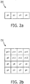
- the multiple thermopiles may be arranged in a line to form a one dimensional thermopile array 200 (comprising pixels p1-p4) as shown in Figure 2a .
- the multiple thermopiles may be arranged in a grid to form a two dimensional thermopile array 250 as shown in Figure 2b .
- the grid may comprise for example a 4x4 array comprising 16 pixels in total (p1-p16), an 8x8 array comprising 64 pixels in total, or any other sized array.
- the thermopile array sensor 2 may be one or two dimensional, comprising any number of pixels.
- the thermopile array sensor 2 provides an output signal which represents real temperature data for each pixel.
- the output interface of the thermopile array sensor 2 may comprise for example an I 2 C interface.
- the controller 1 comprises a control module 5 which is coupled to the thermopile array sensor 2 via a first interface 6a.
- the control module 5 is configured to receive temperature information from the thermopile array sensor 2 via the first interface 6a.
- the control module 5 is further configured to control the amount of light emitted from the luminaire(s) 4 by transmitting appropriate control signals to the luminaire(s) 4 via an interface 6b.
- the luminaire(s) 4 are configured to operate in a plurality of operating states as will be described in further detail herein.
- the functionality of the control module 5 of the controller 1 may be implemented in code (software) stored on a memory comprising one or more storage media, and arranged for execution on a processor comprising on or more processing units.
- the code is configured so as when fetched from the memory and executed on the processor to perform operations in line with embodiments discussed below.
- it is not excluded that some or all of the functionality of the control module 5 is implemented in dedicated hardware circuitry, or configurable hardware circuitry like an FPGA.
- the lighting system 100 may be placed in an outdoor environment, for example the one or more lighting devices 4 may be a component of an outdoor street light 300 suitable for lighting car parks and roads etc.
- the thermopile array sensor 2 Whilst Figure 3 shows the thermopile array sensor 2 being fully integrated into the outdoor street light 300, one or more of the controller 1 and the thermopile array sensor 2 may be housed in a unit separate to the outdoor street light 300, albeit connected to the one or more lighting devices 4 of the outdoor street light 300.
- thermopile array sensor 2 uses a lens (which may be integrated into, or coupled to, the thermopile array sensor 2) to measure the temperature within a sensing region (SR) 302 associated with the thermopile array sensor 2.
- the thermopile array sensor 2 may measure the temperature within its SR 302 at a certain frame rate (for example 10 frames/sec or 1 frame/sec).
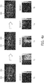
- thermopile array sensor 2 comprising a 4x4 pixel array.
- the object is a vehicle.
- Scenes 402, 404 and 406 illustrate the SR 302 of thermopile array sensor 2 being focused on a road.
- thermopile array sensor 2 In scene 402 a vehicle is approaching, but has not yet entered the SR 302 of thermopile array sensor 2. At this time (t 1 ) a sample (sample 3) of temperature data for each pixel is captured by the thermopile array sensor 2 and supplied to the control module 5 via interface 6a. Based on receiving this temperature data the control module 5 is able to identify a temperature range measured by the pixels in the pixel array which corresponds to when no object is present in the SR 302 of the thermopile array sensor 2 and control the luminaire(s) 4 to operate in a first operating state during which the luminaire(s) 4 illuminate the environment of the lighting system 100 by emitting light at a first illumination level (this may include when the luminaire(s) 4 emit no light i.e.
- illumination level refers to the amount of light output from the luminaire(s) 4.
- the illumination level can be expressed in terms of illuminance (in lux) i.e. in terms of the amount of light emitted from the luminaire(s) 4 that is incident over a plane of interest (e.g. a road surface). It will be appreciated that other photometry units may also be used to express the amount of light output from the luminaire(s) 4.
- thermopile array sensor 2 As the vehicle passes through the SR 302 of thermopile array sensor 2 (shown in scene 404) samples of temperature data for each pixel is captured by the thermopile array sensor 2 and supplied to the control module 5 via interface 6a. As shown in Figure 4a the temperature measured by pixels in the pixel array increases (represented by a lighter shade) due to the presence of the vehicle in the SR 302 of thermopile array sensor 2.
- the control module 5 is configured to monitor the temperature data received from the thermopile array sensor 2. If the temperature data measured by one or more pixel of the pixel array of the thermopile array sensor 2 has reached a predetermined threshold temperature or increases by a predetermined amount above the peak temperature measured by a pixel in the pixel array when no object is present in the SR 302 of the thermopile array sensor 2, then the control module 5 is configured to control the luminaire(s) 4 to operate in a second operating state during which the luminaire(s) 4 illuminate the environment of the lighting system 100 by emitting light at a second illumination level, the second illumination level being higher than the first illumination level.
- thermopile array sensor 2 In scene 406, the vehicle has exited the SR 302 of thermopile array sensor 2. At this time (t 5 ) a sample (sample 7) of temperature data for each pixel is captured by the thermopile array sensor 2 and supplied to the control module 5 via interface 6a. Following a predetermined period during which the temperature measured by the pixels remains in the above temperature range (no object is present in the SR 302 of the thermopile array sensor 2), the control module 5 controls the luminaire(s) 4 to return to operate in the first operating state during which the luminaire(s) 4 illuminate the environment of the lighting system 100 by emitting light at the first illumination level.
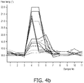
- Figure 4b illustrates the temperature measured by each of the sixteen pixels in the pixel array of the thermopile array sensor 2 over a plurality of samples, in particular the increase in temperate measured by pixels in the pixel array in response to a vehicle passing through the SR 302 of thermopile array sensor 2.
- thermopile array sensor 2 Whilst motion detection of an object performed by a thermopile array sensor 2 is described above with reference to a vehicle passing through the SR 302 of thermopile array sensor 2, it will be appreciated that objects other than vehicles (for example pedestrians) may pass through the SR 302 of thermopile array sensor 2.
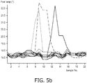
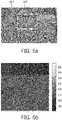
- Figure 5a shows scenes 502, 504 and 506 in which a pedestrian approaches, enters and exits the SR 302 of thermopile array sensor 2 which is being focused on a road.
- thermopile array sensor 2 comprising a 4x4 pixel array in the same manner as that for detecting motion of a vehicle.
- thermopile array sensor 2 when a vehicle passes through the SR 302 of thermopile array sensor 2 differ to the spatiotemporal temperature signatures detected by the thermopile array sensor 2 when a pedestrian passes through the SR 302 of thermopile array sensor 2.
- the control module 5 may be coupled to a memory 3.
- Memory 3 may be arranged to store spatiotemporal temperature signature information for various object types that may pass through the SR 302 of thermopile array sensor 2.
- the control module 5 may be configured to classify the object as one of a plurality of object types (e.g. vehicle or pedestrian) and control the luminaire(s) 4 accordingly.
- thermopile array sensor 2 in response to a pedestrian passing through the SR 302 of thermopile array sensor 2 (shown in scene 504) samples of temperature data for each pixel are captured by the thermopile array sensor 2 and supplied to the control module 5 via interface 6a. As shown in Figure 5a the temperature measured by pixels in the pixel array increases due to the presence of the pedestrian in the SR 302 of thermopile array sensor 2.
- the control module 5 is configured to monitor the temperature data received from the thermopile array sensor 2.
- control module 5 is configured to classify the object as a pedestrian and thereby control the luminaire(s) 4 to operate in a second operating state during which the luminaire(s) 4 illuminate the environment of the lighting system 100 by emitting light at a second illumination level.
- the second illumination level when a pedestrian is detected in the SR 302 of thermopile array sensor 2 may be higher than the second illumination level when a vehicle is detected in the SR 302 of thermopile array sensor 2.
- the second illumination level when a vehicle is detected in the SR 302 of thermopile array sensor 2 may be higher than the second illumination level when a pedestrian is detected in the SR 302 of thermopile array sensor 2.
- control module 5 is configured to control the level of increase of light emitted from the luminaire(s) 4 when an object is detected depending on the type of object detected in the SR 302 of thermopile array sensor 2.
- thermopile array sensor 2 for motion detection and object classification as described above, additional details about the scene around the lighting installation, in particular conditions of the environment in the SR 302 the thermopile array sensor 2, can be of direct value to the lighting infrastructure. That is, the temperature information received from the thermopile array sensor 2 can be re-used by the control module 5 to provide enhanced control of the luminaire(s) 4 based on detected conditions of the environment in the SR 302 of the thermopile array sensor 2.
- thermopile array sensor 2 The various types of conditions of the environment in the SR 302 of the thermopile array sensor 2 which can be detected by the control module 5 based on the temperature information received from the thermopile array sensor 2 are outlined below.
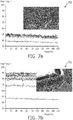
- FIG. 6a shows scene 602 illustrating the SR 302 of thermopile array sensor 2 being focused on both a road and pavement.
- thermopile array sensor 2 The different material properties of asphalt (road) and sand (pavement) result in the pixels of the pixel array of the thermopile array sensor 2 which are focused on the pavement measuring different temperatures to the pixels of the pixel array of the thermopile array sensor 2 which are focused on the road.
- Figure 6b shows the measured temperature for each pixel of the pixel array of the thermopile array sensor 2 captured in one sample.
- the temperature measured by pixels p14, p15, and p16 (focused on the pavement) is lower than the temperature measured by the remaining pixels of the pixel array of the thermopile array sensor 2.
- Figure 6c illustrates this effect over a period of time by showing the measured temperature for each pixel of the pixel array of the thermopile array sensor 2 captured in a plurality of samples.
- the control module 5 may be configured to estimate the road layout based on the temperature data received from the thermopile array sensor 2. For example, the control module 5 may estimate the road layout based by identifying differences in the temperatures measured by pixels of the pixel array of the thermopile array sensor 2.
- the estimated road layout information may be used by the control module 5 to control the plurality of luminaires.
- the control module 5 may control the outdoor lighting devices 4 such that some of the outdoor lighting devices 4 emit light at a higher illumination level than others such that the light which is incident on the pavement is at a different (i.e. higher or lower) illumination level than the light which is incident on the road.
- the controller 1 may be coupled to one or more further sensors (not shown in Figure 1 ) that have a spatial mapping of their SR with the SR 302 of the thermopile array sensor 2.
- the estimated road layout gives an indication of traffic type (pedestrian on kerbside, vehicles on road, etc.) traffic speeds, and direction of travel.
- This information can be used by the control module 5 to tune the one or more further sensors. For example, this information can be used by the control module 5 to mask/filter the processing of the one or more further sensors such that the one or more further sensors are responsive to objects only with specific/desired patterns (detecting vehicles within a particular direction/speed limit, or detect motion differently on different spatial areas/zones).
- Weather conditions of the environment in the SR 302 of the thermopile array sensor 2 can also be detected by the control module 5 based on the temperature data received from the thermopile array sensor 2.
- control module 5 is able to identify weather conditions based on the ratio of the peak temperature measured by a pixel in the pixel array when no object is present in the SR 302 of the thermopile array sensor 2 and the peak temperature measured by a pixel in the pixel array when an object is present in the SR 302 of the thermopile array sensor 2.
- control module 5 may identify a peak temperature measured by a pixel in the pixel array when no object is present in the SR 302 of the thermopile array sensor 2 of approximately 18.5°C, and a peak temperature measured by a pixel in the pixel array when an object is present in the SR 302 of the thermopile array sensor 2 of approximately 21.5°C.
- control module 5 may identify a peak temperature measured by a pixel in the pixel array when no object is present in the SR 302 of the thermopile array sensor 2 of approximately 15°C, and a peak temperature measured by a pixel in the pixel array when an object is present in the SR 302 of the thermopile array sensor 2 of approximately 19°C.
- control module 5 may identify a peak temperature measured by a pixel in the pixel array when no object is present in the SR 302 of the thermopile array sensor 2 of approximately 9°C, and a peak temperature measured by a pixel in the pixel array when an object is present in the SR 302 of the thermopile array sensor 2 of approximately 17.5°C.
- the temperature values above are provided to merely give an indication of the way the temperature readings (and the ratio of the peak temperature measured by a pixel in the pixel array when no object is present in the SR 302 of the thermopile array sensor 2 and the peak temperature measured by a pixel in the pixel array when an object is present in the SR 302 of the thermopile array sensor 2) changes depending on weather conditions and are not intended to limit the present disclosure in any way.
- the control module 5 may be configured to vary the light to be emitted by the luminaire(s) 4 when operating in the first operating state (adjust the first illumination level).
- the illumination level of the light emitted by the luminaire(s) 4 when no object is present in the SR 302 of the thermopile array sensor 2 may vary in dependence of the weather conditions of the SR 302 of the thermopile array sensor 2.
- the control module 5 may be configured to vary the light to be emitted by the luminaire(s) 4 when operating in the second operating state (adjusts the second illumination level).
- the illumination level of the light emitted by the luminaire(s) 4 when an object is present in the SR 302 of the thermopile array sensor 2 may vary in dependence of the weather conditions of the SR 302 of the thermopile array sensor 2.
- the inventors have also recognised that objects in outdoor conditions are exposed to various conditions of sunlight during the course of the day, thereby having an impact on the way the control module 5 detects motion of an object in the SR 302 of the thermopile array sensor 2.
- the inventors have identified that the robustness of the thermopile array sensor 2 decreases in periods of sunset and sundown, and detectability of motion of an object in the SR 302 of the thermopile array sensor 2 by the control module 5 is dependent on ambient temperature. This can result in missed motion detections by the control module 5, thereby bringing down the performance of the lighting system 100.
- control module is configured to detect weather conditions of the environment in the SR 302 of the thermopile array sensor 2 based on the above described peak temperature contrast ratio, and based on the detected weather conditions, select an appropriate threshold temperature that must be measured by one or more pixel of the pixel array of the thermopile array sensor 2 in order for the control module 5 to detect motion in the SR 302 of thermopile array sensor 2 and control the luminaire(s) 4 to operate in the second operating state during which the luminaire(s) 4 illuminate the environment of the lighting system 100 by emitting light at a second illumination level.
- control module 5 is configured to detect weather conditions of the environment in the SR 302 of the thermopile array sensor 2 based on the above described peak temperature contrast ratio, and based on the detected weather conditions, select an appropriate threshold temperature increase (above the peak temperature measured by a pixel in the pixel array when no object is present in the SR 302 of the thermopile array sensor 2) that must be measured by one or more pixel of the pixel array of the thermopile array sensor 2 in order for the control module 5 to detect motion in the SR 302 of thermopile array sensor 2 and control the luminaire(s) 4 to operate in the second operating state during which the luminaire(s) 4 illuminate the environment of the lighting system 100 by emitting light at the second illumination level.
- an appropriate threshold temperature increase above the peak temperature measured by a pixel in the pixel array when no object is present in the SR 302 of the thermopile array sensor 2
- the control module 5 to detect motion in the SR 302 of thermopile array sensor 2 and control the luminaire(s) 4 to operate in the second
- control module 5 may be configured to adapt its motion detection sensitivity based on the detected weather conditions (contrast of the object temperature against the background temperature in the scene).
- the control module 5 may receive the temperature information from a source other than from the thermopile array sensor 2.
- the temperature information can be obtained from a further temperature sensor (not shown in Figure 1 ) coupled to the control module 5.
- the temperature information may be estimated based on receiving time of day information from a timer (not shown in Figure 1 ) coupled to the control module 5.
- the further temperature sensor and timer may be internal components of the controller 1. Alternatively the further temperature sensor and timer may be external to the controller 1.
- thermopile array sensor 2 can also be detected by the control module 5 based on the temperature data received from the thermopile array sensor 2. This is described with reference to Figure 8 .
- Figure 8 illustrates how detection of an object in the SR 302 of the thermopile array sensor 2 is affected by rainfall.
- Figure 8 shows the temperature measured by a single pixel in the pixel array of the thermopile array sensor 2 whilst an object remains in the SR 302 of the thermopile array sensor 2 both during no rainfall and during rainfall.
- the control module 5 is configured to detect when an increase in measured temperature caused by presence of an object in the SR 302 of the thermopile array sensor 2 has increased to a temperature that is lower than a range of increased temperatures that are typically reported due to presence of an object in the SR 302 of the thermopile array sensor 2, in order to detect rainfall.
- control module 5 may be configured to vary the light to be emitted by the luminaire(s) 4 when operating in the first operating state (adjusts the first illumination level).
- the illumination level of the light emitted by the luminaire(s) 4 when no object is present in the SR 302 of the thermopile array sensor 2 may vary in dependence on detected rainfall in the SR 302 of the thermopile array sensor 2.
- control module 5 may be configured to vary the light to be emitted by the luminaire(s) 4 when operating in the second operating state (adjusts the second illumination level).
- the illumination level of the light emitted by the luminaire(s) 4 when an object is present in the SR 302 of the thermopile array sensor 2 may vary in dependence on detected rainfall in the SR 302 of the thermopile array sensor 2.
- thermopile array sensor 2 Stagnation of water (i.e. puddles) on a surface (e.g. road) in the SR 302 the thermopile array sensor 2, and absorption of water into a surface in the SR 302 the thermopile array sensor 2 can also be detected by the control module 5 based on the temperature data received from the thermopile array sensor 2. In particular by the control module 5 monitoring the heating up / cooling down properties of the surface.
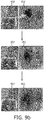
- Figure 9a illustrates how the control module 5 can detect stagnation of water 902 on a surface (e.g. road) in the SR 302 the thermopile array sensor 2 by detecting that the temperature measured by a concentration of pixels of the pixel array of the thermopile array sensor 2 is below a temperature range measured by the remaining pixels of the pixel array of the thermopile array sensor 2.
- the thermal signature shown in Figure 9a illustrates how pixels 952 focused on the stagnation of water 902 report a lower temperature (represented by the darker shade) than pixels not focused on the stagnation of water 902.
- thermopile array sensor 2 Over time the stagnation of water 902 will be absorbed into the surface in the SR 302 the thermopile array sensor 2. For example, water on an asphalt surface is absorbed into the asphalt surface over time.
- thermopile array sensor 2 The absorption of water into a surface (e.g. road) in the SR 302 the thermopile array sensor 2 can also be detected by the control module 5 monitoring the temperature data received from the thermopile array sensor 2.
- Figure 9b illustrates how the control module 5 can detect absorption of water into a surface (e.g. road) in the SR 302 the thermopile array sensor 2 by monitoring how the temperature measured by the initial concentration of pixels 952 and the temperature measured by the pixels of the pixel array of the thermopile array sensor 2 adjacent to the initial concentration of pixels 952, changes over time.
- a surface e.g. road
- control module 5 may be configured to vary the light to be emitted by the luminaire(s) 4 when operating in the first operating state (adjusts the first illumination level).
- the illumination level of the light emitted by the luminaire(s) 4 when no object is present in the SR 302 of the thermopile array sensor 2 may vary in dependence on detecting stagnated water on a surface (or absorbed water in a surface) of the SR 302 of the thermopile array sensor 2.
- control module 5 may be configured to vary the light to be emitted by the luminaire(s) 4 when operating in the second operating state (adjusts the second illumination level).
- the illumination level of the light emitted by the luminaire(s) 4 when an object is present in the SR 302 of the thermopile array sensor 2 may vary in dependence on detecting stagnated water on a surface (or absorbed water in a surface) of the SR 302 of the thermopile array sensor 2.
- thermopile array sensor 2 various types of conditions (road layout, weather conditions, rainfall, road conditions) of the environment in the SR 302 of the thermopile array sensor 2 can be detected by the control module 5 based on the temperature information received from the thermopile array sensor 2 and used to control the luminaire(s) 4.
- the weather conditions, rainfall information, and road condition information may be reported by the controller 1 via an interface (not shown in Figure 1 ) to an external service (i.e. weather monitoring station or highways management station) to alert people to the conditions in the environment of the thermopile array sensor 2.
- an external service i.e. weather monitoring station or highways management station
- the SR 302 of the thermopile array sensor 2 may optionally be controllable using orientation control means (not shown in Figure 1 ) coupled to the thermopile array sensor 2, whereby the orientation control means is configured to control the SR 302 of the thermopile array sensor 2 in dependence on the conditions (road layout, weather conditions, rainfall, road conditions) of the environment in the SR 302 of the thermopile array sensor 2.
- the orientation control means may comprise one or more electro-mechanical motors.
- thermopile array sensor 2 may comprise an input (not shown in Figure 1 ) via which orientation information may be received from a remote source such that the SR 302 of the thermopile array sensor 2 can be monitored and corrected or compensated for.
- thermopile array sensor 2 may be one or two dimensional, comprising any number of pixels.
- movement of an object is expected to be in a certain direction. For example, at a pedestrian crossing a person is expected to move within the confines of the pedestrian crossing to cross a road, along a sidewalk a person is expected to move along the sidewalk in one of two expected directions, and a vehicle is expected to move in a certain direction as it travels on a highway.
- the inventors have identified that when the SR 302 associated with a one dimensional thermopile array sensor 2 is focused on such a road topology, the one dimensional thermopile array sensor 2 can be optimally oriented such that the control module 5 is able to estimate the direction of motion in the SR 302 of the one dimensional thermopile array sensor 2 (which otherwise requires a two dimensional thermopile array sensor) based on the temperature data output from each pixel of the one dimensional thermopile array sensor 2.
- Figure 10 illustrates the SR of the one dimensional thermopile array 200 (comprising pixels p1-p4) shown in Figure 2a . Whilst Figure 10 shows the one dimensional thermopile array 200 being fully integrated into an outdoor street light 1000, at least one of the controller 1 and the one dimensional thermopile array 200 may be housed in a unit separate to the outdoor street light 300, albeit connected to the one or more lighting devices 4 of the outdoor street light 300.
- thermopile array sensor 200 In order to illustrate how direction information can be extracted from the temperature data output from each pixel of the one dimensional thermopile array sensor 200, we refer to an example scenario in which a person starting from a position indicated by 'A' in Figure 10 crosses a road to a position indicated by 'B' in Figure 10 (in a first direction), and then returns to position 'A' in the opposite direction.
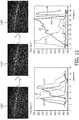
- Figure 11 shows scenes 1102, 1104 and 1106 in which a person starting from position A crosses a road and walks through the SR 302 of thermopile array sensor 2 and arrives at position B (note that Figure 11 does not show scenes in relation to when a person crosses the road and returns from position B to position A).
- the left-hand graph illustrates the temperature measured by each of the four pixels (p1-p4) in the pixel array of the one dimensional thermopile array 200 over a plurality of samples, in particular the increase and subsequent decrease in temperature measured by each of the four pixels as a person starting from position A crosses a road and walks through the SR 302 of thermopile array sensor 2 and arrives at position B.
- the right-hand graph illustrates the temperature measured by each of the four pixels (p1-p4) in the pixel array of the one dimensional thermopile array 200 over a plurality of samples, in particular the increase and subsequent decrease in temperature measured by each of the four pixels as a person starting from position B crosses the road and walks through the SR 302 of thermopile array sensor 2 and arrives at position A.
- control module 5 is configured to estimate the direction of motion in the SR 302 of the one dimensional thermopile array sensor 200 based on identifying the order that the pixels of the array report an increase in measured temperature. For example, when a person walks from position A to position B, as shown in the left-hand graph of Figure 11 pixel p4 first reports an increase in measured temperature, followed by pixel p3, then pixel p2 and finally pixel p1. However when a person walks from position B to position A, as shown in the right-hand graph of Figure 11 pixel p1 first reports an increase in measured temperature, followed by pixel p2, then pixel p3 and finally pixel p4.
- the control module 5 may identify an increase is measured temperature of a pixel when the temperature measured by that pixel has reached a predetermined threshold temperature or increases by a predetermined amount above the peak temperature measured by a pixel in the pixel array when no object is present in the SR 302 of the one dimensional thermopile array sensor 200,
- control module 5 has a priori knowledge of the expected order that the pixels of the array report an increase in measured temperature when an object moves in the expected direction(s) of movement of an object in the SR 302 of the one dimensional thermopile array sensor 200 given the road topology.
- the control module 5 is configured to only control the luminaire(s) 4 in dependence on detecting motion in the expected direction(s) (identified based on the order that the pixels of the array report an increase in measured temperature).
- Crosstalk refers to the phenomenon where radiation received at one pixel radiates outwards to affect neighboring pixels.
- the cross-talk between neighbouring pixels impacts the way a temperature reading is observed on a pixel, and its neighbours. Often efforts are made to minimize this crosstalk; however the inventors have recognized that the spatiotemporal crosstalk between neighbouring pixels of the one dimensional thermopile array sensor 200 can be exploited to estimate the direction of motion in the SR 302 of the one dimensional thermopile array sensor 200.
- the inventors have recognized that the direction of incident radiation varies the crosstalk experienced by the one dimensional thermopile array sensor 200, in particular that the crosstalk affects the gradient of a measured temperature increase output from a pixel and the gradient of a measured temperature decrease output from a pixel, and that the direction of incident radiation varies the gradients of measured temperature increases and temperature decreases output from the pixels of the one dimensional thermopile array sensor 200
- control module 5 is configured to estimate the direction of motion in the SR 302 of the one dimensional thermopile array sensor 200 based on the gradients of measured temperature increases and temperature decreases output from the pixels of the one dimensional thermopile array sensor 200.
- control module 5 has a priori knowledge of the expected gradients of measured temperature increases and temperature decreases output from the pixels of the one dimensional thermopile array sensor 200 when an object moves in the expected direction(s) of movement of an object in the SR 302 of the one dimensional thermopile array sensor 200 given the road topology.
- the control module 5 is configured to only control the luminaire(s) 4 in dependence on detecting motion in the expected direction(s) (identified based on gradients of measured temperature increases and temperature decreases output from the pixels of the one dimensional thermopile array sensor 200).
- the orientation of the one dimensional thermopile array sensor 200 should be offset from its most sensitive direction (which is the same as the expected direction) by an angle ⁇ in either direction of rotation (clockwise or anti-clockwise).
- the angle ⁇ may be in the range of 0° ⁇ ⁇ ⁇ 90° in dependence on the sensitivity/efficiency of the one dimensional thermopile array sensor 200.
- the temperature sensor 2 may be any sensor comprising a plurality of temperature sensing elements that provides an output signal which represents real temperature data for each temperature sensing element.
- the temperature sensor 2 may comprise a set of cascaded PIR elements (e.g. in a PIR curtain motion detector).
- a computer program may be stored/distributed on a suitable medium, such as an optical storage medium or a solid-state medium supplied together with or as part of other hardware, but may also be distributed in other forms, such as via the Internet or other wired or wireless telecommunication systems. Any reference signs in the claims should not be construed as limiting the scope.
Landscapes
- Physics & Mathematics (AREA)
- General Physics & Mathematics (AREA)
- Engineering & Computer Science (AREA)
- Spectroscopy & Molecular Physics (AREA)
- General Engineering & Computer Science (AREA)
- Multimedia (AREA)
- Theoretical Computer Science (AREA)
- Circuit Arrangement For Electric Light Sources In General (AREA)
- Arrangement Of Elements, Cooling, Sealing, Or The Like Of Lighting Devices (AREA)
Claims (15)
- Dispositif de commande (1) comprenant :une sortie (6b) pour commander un ou plusieurs dispositifs d'éclairage extérieur (4) pour éclairer un environnement extérieur, dans lequel les un ou plusieurs dispositifs d'éclairage extérieur émettent une lumière à un niveau d'éclairement ;une entrée (6a) pour recevoir des informations de température à partir d'un capteur de température (2) comprenant une pluralité d'éléments de détection de température ; etun module de commande (5) configuré pour :utiliser les informations de température reçues à partir du capteur de température pour détecter un mouvement d'un objet dans une région de détection du capteur de température et commander le niveau d'éclairement des un ou plusieurs dispositifs d'éclairage sur la base du mouvement détecté ; etutiliser les informations de température reçues à partir du capteur de température pour détecter des conditions environnementales dudit environnement dans ladite région de détection et en outre commander un seuil de température pour la détection de mouvement sur la base des conditions environnementales détectées.
- Dispositif de commande selon la revendication 1, dans lequel le module de commande est en outre configuré pour classer l'objet comme étant l'un d'une pluralité de types d'objet et commander les un ou plusieurs dispositifs d'éclairage sur la base du type d'objet.
- Dispositif de commande selon la revendication 1 ou 2, dans lequel les conditions environnementales détectées dudit environnement dans ladite région de détection comprennent des informations sur la configuration de la route, dans lequel le module de commande est configuré pour commander les un ou plusieurs dispositifs d'éclairage sur la base des informations détectées sur la configuration de la route.
- Dispositif de commande selon une quelconque revendication précédente, dans lequel les conditions environnementales détectées dudit environnement dans ladite région de détection comprennent les conditions météorologiques, dans lequel le module de commande est configuré pour :
détecter lesdites conditions météorologiques sur la base d'un rapport d'une température maximale mesurée par le capteur de température lorsqu'aucun objet n'est présent dans la région de détection du capteur de température et d'une température maximale mesurée par le capteur de température lorsqu'un objet est présent dans la région de détection du capteur de température ; et commander les un ou plusieurs dispositifs d'éclairage sur la base des conditions météorologiques détectées. - Dispositif de commande selon la revendication 4, dans lequel le module de commande est configuré pour adapter sa sensibilité de détection de mouvement sur la base du rapport d'une température maximale mesurée par le capteur de température lorsqu'aucun objet n'est présent dans la région de détection du capteur de température et d'une température maximale mesurée par le capteur de température lorsqu'un objet est présent dans la région de détection du capteur de température.
- Dispositif de commande selon l'une quelconque des revendications 1 à 4, dans lequel le module de commande est configuré pour adapter sa sensibilité de détection de mouvement sur la base (i) des informations de température reçues à partir d'un capteur de température supplémentaire couplé audit module de commande, ou (ii) des informations sur le moment de la journée reçues à partir d'une minuterie couplée audit module de commande.
- Dispositif de commande selon une quelconque revendication précédente, dans lequel le module de commande est configuré pour détecter des précipitations dans ledit environnement dans ladite région de détection en utilisant les informations de température reçues à partir du capteur de température et en outre commander les un ou plusieurs dispositifs d'éclairage sur la base des précipitations détectées.
- Dispositif de commande selon une quelconque revendication précédente, dans lequel les conditions environnementales détectées dudit environnement dans ladite région de détection comprennent une stagnation d'eau sur une surface dans ladite région de détection, dans lequel le module de commande est configuré pour commander les un ou plusieurs dispositifs d'éclairage sur la base de la stagnation d'eau détectée.
- Dispositif de commande selon une quelconque revendication précédente, dans lequel les conditions environnementales détectées dudit environnement dans ladite région de détection comprennent l'absorption d'eau dans une surface dans ladite région de détection, dans lequel le module de commande est configuré pour commander les un ou plusieurs dispositifs d'éclairage sur la base de l'absorption d'eau détectée dans la surface.
- Dispositif de commande selon une quelconque revendication précédente, dans lequel le capteur de température est un capteur à réseau de thermopiles unidimensionnel (200) et le module de commande est en outre configuré pour :détecter la direction de mouvement d'un objet dans la région de détection du capteur à réseau de thermopiles unidimensionnel sur la base des informations de température reçues à partir du capteur à réseau de thermopiles unidimensionnel ; etcommander les un ou plusieurs dispositifs d'éclairage sur la base de la direction de mouvement détectée.
- Système d'éclairage extérieur (100) comprenant :le dispositif de commande (1) selon une quelconque revendication précédente ;les un ou plusieurs dispositifs d'éclairage (4) ; etle capteur de température (2).
- Système d'éclairage extérieur selon la revendication 11, dans lequel l'orientation de la région de détection du capteur de température est commandée sur la base des conditions environnementales détectées dudit environnement dans ladite région de détection en utilisant un moyen de commande d'orientation couplé au capteur de température.
- Système d'éclairage extérieur selon la revendication 11, dans lequel le capteur de température comprend une entrée pour recevoir des informations d'orientation à partir d'une source distante, et l'orientation de la région de détection du capteur de température est commandée sur la base desdites informations d'orientation reçues.
- Système d'éclairage extérieur selon l'une quelconque des revendications 11 à 13, dans lequel le capteur de température est un capteur à réseau de thermopiles.
- Produit de programme informatique pour commander un ou plusieurs dispositifs d'éclairage extérieur (4) pour éclairer un environnement extérieur, dans lequel les un ou plusieurs dispositifs d'éclairage extérieur émettent une lumière à un niveau d'éclairement, le produit de programme informatique comprenant un code incorporé sur un support lisible par ordinateur et étant configuré, lorsqu'il est exécuté sur un processeur, pour :recevoir des informations de température à partir d'un capteur de température (2) comprenant une pluralité d'éléments de détection de température ;utiliser les informations de température reçues à partir du capteur de température pour détecter un mouvement dans une région de détection du capteur de température et commander le niveau d'éclairement des un ou plusieurs dispositifs d'éclairage sur la base du mouvement détecté ; etutiliser les informations de température reçues à partir du capteur de température pour détecter les conditions environnementales dudit environnement dans ladite région de détection et en outre commander un seuil de température pour la détection de mouvement sur la base des conditions environnementales détectées.
Priority Applications (1)
| Application Number | Priority Date | Filing Date | Title |
|---|---|---|---|
| EP14824493.2A EP3095070B1 (fr) | 2014-01-16 | 2014-12-30 | Détection thermique |
Applications Claiming Priority (3)
| Application Number | Priority Date | Filing Date | Title |
|---|---|---|---|
| EP14151454 | 2014-01-16 | ||
| PCT/EP2014/079423 WO2015106949A1 (fr) | 2014-01-16 | 2014-12-30 | Détection thermique |
| EP14824493.2A EP3095070B1 (fr) | 2014-01-16 | 2014-12-30 | Détection thermique |
Publications (2)
| Publication Number | Publication Date |
|---|---|
| EP3095070A1 EP3095070A1 (fr) | 2016-11-23 |
| EP3095070B1 true EP3095070B1 (fr) | 2019-11-20 |
Family
ID=49955953
Family Applications (1)
| Application Number | Title | Priority Date | Filing Date |
|---|---|---|---|
| EP14824493.2A Not-in-force EP3095070B1 (fr) | 2014-01-16 | 2014-12-30 | Détection thermique |
Country Status (6)
| Country | Link |
|---|---|
| US (1) | US10136502B2 (fr) |
| EP (1) | EP3095070B1 (fr) |
| JP (1) | JP6422984B2 (fr) |
| CN (1) | CN106133749B (fr) |
| RU (1) | RU2669547C2 (fr) |
| WO (1) | WO2015106949A1 (fr) |
Families Citing this family (5)
| Publication number | Priority date | Publication date | Assignee | Title |
|---|---|---|---|---|
| CN107409462B (zh) * | 2015-04-01 | 2020-01-17 | 飞利浦照明控股有限公司 | 降水感测照明器 |
| EP3380898B1 (fr) | 2015-11-24 | 2020-01-08 | Signify Holding B.V. | Système et procédé permettant de surveiller de drainage de l'eau |
| CN110462698B (zh) * | 2017-04-06 | 2022-05-17 | 昕诺飞控股有限公司 | 照明系统和控制照明系统的方法 |
| EP3789978B1 (fr) * | 2019-09-04 | 2021-07-28 | Rade Tecnologías, S. L. | Système et procédé pour fournir des informations relatives à la présence dans un espace |
| CN115298525A (zh) * | 2020-04-02 | 2022-11-04 | 昕诺飞控股有限公司 | 传感器设备 |
Family Cites Families (24)
| Publication number | Priority date | Publication date | Assignee | Title |
|---|---|---|---|---|
| JP3586922B2 (ja) | 1995-03-31 | 2004-11-10 | 松下電工株式会社 | 照明制御システム |
| US5839821A (en) | 1996-12-23 | 1998-11-24 | Lezotte; Bruce A. | Flashlight with forward looking sensing of thermal bodies |
| JPH10239450A (ja) | 1997-02-21 | 1998-09-11 | Honda Denshi Giken:Kk | 赤外線人体検知装置 |
| JP3991544B2 (ja) | 2000-01-26 | 2007-10-17 | 松下電工株式会社 | 熱線センサ付ライト |
| JP2002043068A (ja) * | 2000-07-24 | 2002-02-08 | Sofutekku:Kk | 街灯用点灯システム及びこのシステムを用いた街灯 |
| JP2008026235A (ja) * | 2006-07-24 | 2008-02-07 | Sumitomo Electric Ind Ltd | 車両検知装置及び信号制御システム |
| KR20090049587A (ko) * | 2006-09-11 | 2009-05-18 | 컴라이트 에이에스 | 공공 조명을 위한 제어 장치, 시스템 및 방법 |
| JP2007073058A (ja) * | 2006-09-28 | 2007-03-22 | Sumitomo Electric Ind Ltd | 車両検知器 |
| WO2008122935A1 (fr) | 2007-04-04 | 2008-10-16 | Koninklijke Philips Electronics N.V. | Mesure et affichage à distance |
| DE102008062674B3 (de) * | 2008-12-17 | 2010-06-17 | Osram Gesellschaft mit beschränkter Haftung | Verfahren zum Steuern des Abstrahlverhaltens von Leuchten in einer Anordnung aus einer Mehrzahl von Leuchten sowie Anordnung aus Mehrzahl von Leuchten |
| KR20090108971A (ko) * | 2008-04-14 | 2009-10-19 | 홍익대학교 산학협력단 | 계절 및 온도에 따른 조명조절용 유비쿼터스 가로등 |
| KR101037093B1 (ko) | 2009-07-24 | 2011-05-26 | 이화랑 | 복합센서를 이용한 가로등 제어장치 |
| US20120217880A1 (en) * | 2009-11-03 | 2012-08-30 | Koninklijke Philips Electronics, N.V. | Object-sensing lighting network and control system therefor |
| US8344660B2 (en) * | 2009-12-16 | 2013-01-01 | Enlighted, Inc. | Lighting control |
| CN201688296U (zh) * | 2010-06-04 | 2010-12-29 | 闾卫星 | 一种照度路灯系统 |
| CN102014560B (zh) * | 2010-11-24 | 2012-11-28 | 四川省桑瑞光辉标识系统股份有限公司 | 一种自适应led照明装置及其控制方法 |
| US8890435B2 (en) * | 2011-03-11 | 2014-11-18 | Ilumi Solutions, Inc. | Wireless lighting control system |
| KR20130016660A (ko) * | 2011-08-08 | 2013-02-18 | (주) 유원컴텍 | 카메라센서의 모션 감지 기능을 이용하여 조명 램프의 점멸 혹은 조도를 조절하는 기능을 제공하는 가로등 |
| KR20130031727A (ko) | 2011-09-21 | 2013-03-29 | 주식회사 유멘토스 | 인체 유무 감지를 통한 에너지 절감 시스템 |
| CN202484677U (zh) | 2012-03-01 | 2012-10-10 | 浙江亿科智能科技有限公司 | 光随人动灯 |
| US9137878B2 (en) * | 2012-03-21 | 2015-09-15 | Osram Sylvania Inc. | Dynamic lighting based on activity type |
| JP5890261B2 (ja) * | 2012-06-21 | 2016-03-22 | アズビル株式会社 | 温度検出範囲特定装置および方法 |
| US9271375B2 (en) * | 2013-02-25 | 2016-02-23 | Leviton Manufacturing Company, Inc. | System and method for occupancy sensing with enhanced functionality |
| US9277630B2 (en) * | 2013-11-08 | 2016-03-01 | Zachary Leonid Braunstein | Apparatus intelligent parallel view LED light, methods of configuration and controls |
-
2014
- 2014-12-30 JP JP2016546459A patent/JP6422984B2/ja not_active Expired - Fee Related
- 2014-12-30 US US15/111,924 patent/US10136502B2/en not_active Expired - Fee Related
- 2014-12-30 RU RU2016133379A patent/RU2669547C2/ru active
- 2014-12-30 CN CN201480073339.2A patent/CN106133749B/zh not_active Expired - Fee Related
- 2014-12-30 EP EP14824493.2A patent/EP3095070B1/fr not_active Not-in-force
- 2014-12-30 WO PCT/EP2014/079423 patent/WO2015106949A1/fr active Application Filing
Non-Patent Citations (1)
| Title |
|---|
| None * |
Also Published As
| Publication number | Publication date |
|---|---|
| CN106133749A (zh) | 2016-11-16 |
| EP3095070A1 (fr) | 2016-11-23 |
| RU2669547C2 (ru) | 2018-10-11 |
| US20160338175A1 (en) | 2016-11-17 |
| JP6422984B2 (ja) | 2018-11-14 |
| WO2015106949A1 (fr) | 2015-07-23 |
| CN106133749B (zh) | 2019-07-23 |
| RU2016133379A (ru) | 2018-02-20 |
| US10136502B2 (en) | 2018-11-20 |
| RU2016133379A3 (fr) | 2018-05-24 |
| JP2017503325A (ja) | 2017-01-26 |
Similar Documents
| Publication | Publication Date | Title |
|---|---|---|
| US20140112537A1 (en) | Systems and methods for intelligent monitoring of thoroughfares using thermal imaging | |
| EP3095070B1 (fr) | Détection thermique | |
| US11143749B2 (en) | Object detection system and method | |
| US9801257B2 (en) | Light reflectance based detection | |
| EP3039947B1 (fr) | Réseau de capteurs ayant des paramètres de détection adaptatifs basés sur des informations d'état provenant des luminaires voisins et/ou des dispositifs connectés | |
| CA2691141C (fr) | Systeme d'eclairage avec fonctions de gestion de trafic | |
| EP3850916B1 (fr) | Système de luminaire permettant de déterminer des informations météorologiques | |
| NL2010323C2 (en) | Motion detector system, lighting system with such system and method for detecting moving vehicles and/or pedestrians. | |
| KR100962434B1 (ko) | 감시 카메라 | |
| KR101667350B1 (ko) | Cctv 카메라와 조명이 연동 가능한 보안 시스템 | |
| Mohring et al. | A controlled trial of a commodity sensors for a streetlight-mounted traffic detection system | |
| KR102679895B1 (ko) | 블랙 아이스 생성 방지 시스템 | |
| Bos et al. | Outdoor lighting versus surveillance camera systems in electrical substations ČEPS |
Legal Events
| Date | Code | Title | Description |
|---|---|---|---|
| PUAI | Public reference made under article 153(3) epc to a published international application that has entered the european phase |
Free format text: ORIGINAL CODE: 0009012 |
|
| 17P | Request for examination filed |
Effective date: 20160816 |
|
| AK | Designated contracting states |
Kind code of ref document: A1 Designated state(s): AL AT BE BG CH CY CZ DE DK EE ES FI FR GB GR HR HU IE IS IT LI LT LU LV MC MK MT NL NO PL PT RO RS SE SI SK SM TR |
|
| AX | Request for extension of the european patent |
Extension state: BA ME |
|
| DAX | Request for extension of the european patent (deleted) | ||
| RIN1 | Information on inventor provided before grant (corrected) |
Inventor name: BROERS, HARRY Inventor name: RAJAGOPALAN, RUBEN |
|
| RAP1 | Party data changed (applicant data changed or rights of an application transferred) |
Owner name: PHILIPS LIGHTING HOLDING B.V. |
|
| RAP1 | Party data changed (applicant data changed or rights of an application transferred) |
Owner name: SIGNIFY HOLDING B.V. |
|
| STAA | Information on the status of an ep patent application or granted ep patent |
Free format text: STATUS: EXAMINATION IS IN PROGRESS |
|
| 17Q | First examination report despatched |
Effective date: 20190417 |
|
| GRAP | Despatch of communication of intention to grant a patent |
Free format text: ORIGINAL CODE: EPIDOSNIGR1 |
|
| STAA | Information on the status of an ep patent application or granted ep patent |
Free format text: STATUS: GRANT OF PATENT IS INTENDED |
|
| RIC1 | Information provided on ipc code assigned before grant |
Ipc: G06K 9/00 20060101AFI20190613BHEP Ipc: F21W 131/103 20060101ALI20190613BHEP Ipc: G01J 5/00 20060101ALI20190613BHEP Ipc: F21S 2/00 20160101ALI20190613BHEP Ipc: G01J 5/12 20060101ALI20190613BHEP |
|
| INTG | Intention to grant announced |
Effective date: 20190628 |
|
| GRAA | (expected) grant |
Free format text: ORIGINAL CODE: 0009210 |
|
| STAA | Information on the status of an ep patent application or granted ep patent |
Free format text: STATUS: THE PATENT HAS BEEN GRANTED |
|
| GRAS | Grant fee paid |
Free format text: ORIGINAL CODE: EPIDOSNIGR3 |
|
| AK | Designated contracting states |
Kind code of ref document: B1 Designated state(s): AL AT BE BG CH CY CZ DE DK EE ES FI FR GB GR HR HU IE IS IT LI LT LU LV MC MK MT NL NO PL PT RO RS SE SI SK SM TR |
|
| REG | Reference to a national code |
Ref country code: GB Ref legal event code: FG4D |
|
| REG | Reference to a national code |
Ref country code: CH Ref legal event code: EP |
|
| REG | Reference to a national code |
Ref country code: IE Ref legal event code: FG4D |
|
| REG | Reference to a national code |
Ref country code: DE Ref legal event code: R096 Ref document number: 602014057218 Country of ref document: DE |
|
| REG | Reference to a national code |
Ref country code: AT Ref legal event code: REF Ref document number: 1204998 Country of ref document: AT Kind code of ref document: T Effective date: 20191215 |
|
| REG | Reference to a national code |
Ref country code: NL Ref legal event code: MP Effective date: 20191120 |
|
| REG | Reference to a national code |
Ref country code: LT Ref legal event code: MG4D |
|
| PG25 | Lapsed in a contracting state [announced via postgrant information from national office to epo] |
Ref country code: BG Free format text: LAPSE BECAUSE OF FAILURE TO SUBMIT A TRANSLATION OF THE DESCRIPTION OR TO PAY THE FEE WITHIN THE PRESCRIBED TIME-LIMIT Effective date: 20200220 Ref country code: FI Free format text: LAPSE BECAUSE OF FAILURE TO SUBMIT A TRANSLATION OF THE DESCRIPTION OR TO PAY THE FEE WITHIN THE PRESCRIBED TIME-LIMIT Effective date: 20191120 Ref country code: SE Free format text: LAPSE BECAUSE OF FAILURE TO SUBMIT A TRANSLATION OF THE DESCRIPTION OR TO PAY THE FEE WITHIN THE PRESCRIBED TIME-LIMIT Effective date: 20191120 Ref country code: NL Free format text: LAPSE BECAUSE OF FAILURE TO SUBMIT A TRANSLATION OF THE DESCRIPTION OR TO PAY THE FEE WITHIN THE PRESCRIBED TIME-LIMIT Effective date: 20191120 Ref country code: LV Free format text: LAPSE BECAUSE OF FAILURE TO SUBMIT A TRANSLATION OF THE DESCRIPTION OR TO PAY THE FEE WITHIN THE PRESCRIBED TIME-LIMIT Effective date: 20191120 Ref country code: LT Free format text: LAPSE BECAUSE OF FAILURE TO SUBMIT A TRANSLATION OF THE DESCRIPTION OR TO PAY THE FEE WITHIN THE PRESCRIBED TIME-LIMIT Effective date: 20191120 Ref country code: NO Free format text: LAPSE BECAUSE OF FAILURE TO SUBMIT A TRANSLATION OF THE DESCRIPTION OR TO PAY THE FEE WITHIN THE PRESCRIBED TIME-LIMIT Effective date: 20200220 Ref country code: GR Free format text: LAPSE BECAUSE OF FAILURE TO SUBMIT A TRANSLATION OF THE DESCRIPTION OR TO PAY THE FEE WITHIN THE PRESCRIBED TIME-LIMIT Effective date: 20200221 |
|
| PG25 | Lapsed in a contracting state [announced via postgrant information from national office to epo] |
Ref country code: IS Free format text: LAPSE BECAUSE OF FAILURE TO SUBMIT A TRANSLATION OF THE DESCRIPTION OR TO PAY THE FEE WITHIN THE PRESCRIBED TIME-LIMIT Effective date: 20200320 Ref country code: HR Free format text: LAPSE BECAUSE OF FAILURE TO SUBMIT A TRANSLATION OF THE DESCRIPTION OR TO PAY THE FEE WITHIN THE PRESCRIBED TIME-LIMIT Effective date: 20191120 Ref country code: RS Free format text: LAPSE BECAUSE OF FAILURE TO SUBMIT A TRANSLATION OF THE DESCRIPTION OR TO PAY THE FEE WITHIN THE PRESCRIBED TIME-LIMIT Effective date: 20191120 |
|
| PG25 | Lapsed in a contracting state [announced via postgrant information from national office to epo] |
Ref country code: AL Free format text: LAPSE BECAUSE OF FAILURE TO SUBMIT A TRANSLATION OF THE DESCRIPTION OR TO PAY THE FEE WITHIN THE PRESCRIBED TIME-LIMIT Effective date: 20191120 |
|
| PG25 | Lapsed in a contracting state [announced via postgrant information from national office to epo] |
Ref country code: EE Free format text: LAPSE BECAUSE OF FAILURE TO SUBMIT A TRANSLATION OF THE DESCRIPTION OR TO PAY THE FEE WITHIN THE PRESCRIBED TIME-LIMIT Effective date: 20191120 Ref country code: ES Free format text: LAPSE BECAUSE OF FAILURE TO SUBMIT A TRANSLATION OF THE DESCRIPTION OR TO PAY THE FEE WITHIN THE PRESCRIBED TIME-LIMIT Effective date: 20191120 Ref country code: CZ Free format text: LAPSE BECAUSE OF FAILURE TO SUBMIT A TRANSLATION OF THE DESCRIPTION OR TO PAY THE FEE WITHIN THE PRESCRIBED TIME-LIMIT Effective date: 20191120 Ref country code: RO Free format text: LAPSE BECAUSE OF FAILURE TO SUBMIT A TRANSLATION OF THE DESCRIPTION OR TO PAY THE FEE WITHIN THE PRESCRIBED TIME-LIMIT Effective date: 20191120 Ref country code: PT Free format text: LAPSE BECAUSE OF FAILURE TO SUBMIT A TRANSLATION OF THE DESCRIPTION OR TO PAY THE FEE WITHIN THE PRESCRIBED TIME-LIMIT Effective date: 20200412 Ref country code: DK Free format text: LAPSE BECAUSE OF FAILURE TO SUBMIT A TRANSLATION OF THE DESCRIPTION OR TO PAY THE FEE WITHIN THE PRESCRIBED TIME-LIMIT Effective date: 20191120 |
|
| REG | Reference to a national code |
Ref country code: CH Ref legal event code: PL |
|
| REG | Reference to a national code |
Ref country code: AT Ref legal event code: MK05 Ref document number: 1204998 Country of ref document: AT Kind code of ref document: T Effective date: 20191120 |
|
| REG | Reference to a national code |
Ref country code: DE Ref legal event code: R097 Ref document number: 602014057218 Country of ref document: DE |
|
| REG | Reference to a national code |
Ref country code: BE Ref legal event code: MM Effective date: 20191231 |
|
| PG25 | Lapsed in a contracting state [announced via postgrant information from national office to epo] |
Ref country code: MC Free format text: LAPSE BECAUSE OF FAILURE TO SUBMIT A TRANSLATION OF THE DESCRIPTION OR TO PAY THE FEE WITHIN THE PRESCRIBED TIME-LIMIT Effective date: 20191120 Ref country code: SK Free format text: LAPSE BECAUSE OF FAILURE TO SUBMIT A TRANSLATION OF THE DESCRIPTION OR TO PAY THE FEE WITHIN THE PRESCRIBED TIME-LIMIT Effective date: 20191120 Ref country code: SM Free format text: LAPSE BECAUSE OF FAILURE TO SUBMIT A TRANSLATION OF THE DESCRIPTION OR TO PAY THE FEE WITHIN THE PRESCRIBED TIME-LIMIT Effective date: 20191120 |
|
| PLBE | No opposition filed within time limit |
Free format text: ORIGINAL CODE: 0009261 |
|
| STAA | Information on the status of an ep patent application or granted ep patent |
Free format text: STATUS: NO OPPOSITION FILED WITHIN TIME LIMIT |
|
| 26N | No opposition filed |
Effective date: 20200821 |
|
| PG25 | Lapsed in a contracting state [announced via postgrant information from national office to epo] |
Ref country code: IE Free format text: LAPSE BECAUSE OF NON-PAYMENT OF DUE FEES Effective date: 20191230 Ref country code: LU Free format text: LAPSE BECAUSE OF NON-PAYMENT OF DUE FEES Effective date: 20191230 |
|
| PG25 | Lapsed in a contracting state [announced via postgrant information from national office to epo] |
Ref country code: PL Free format text: LAPSE BECAUSE OF FAILURE TO SUBMIT A TRANSLATION OF THE DESCRIPTION OR TO PAY THE FEE WITHIN THE PRESCRIBED TIME-LIMIT Effective date: 20191120 Ref country code: AT Free format text: LAPSE BECAUSE OF FAILURE TO SUBMIT A TRANSLATION OF THE DESCRIPTION OR TO PAY THE FEE WITHIN THE PRESCRIBED TIME-LIMIT Effective date: 20191120 Ref country code: SI Free format text: LAPSE BECAUSE OF FAILURE TO SUBMIT A TRANSLATION OF THE DESCRIPTION OR TO PAY THE FEE WITHIN THE PRESCRIBED TIME-LIMIT Effective date: 20191120 Ref country code: CH Free format text: LAPSE BECAUSE OF NON-PAYMENT OF DUE FEES Effective date: 20191231 Ref country code: LI Free format text: LAPSE BECAUSE OF NON-PAYMENT OF DUE FEES Effective date: 20191231 Ref country code: BE Free format text: LAPSE BECAUSE OF NON-PAYMENT OF DUE FEES Effective date: 20191231 |
|
| PG25 | Lapsed in a contracting state [announced via postgrant information from national office to epo] |
Ref country code: IT Free format text: LAPSE BECAUSE OF FAILURE TO SUBMIT A TRANSLATION OF THE DESCRIPTION OR TO PAY THE FEE WITHIN THE PRESCRIBED TIME-LIMIT Effective date: 20191120 |
|
| PGFP | Annual fee paid to national office [announced via postgrant information from national office to epo] |
Ref country code: FR Payment date: 20201229 Year of fee payment: 7 Ref country code: GB Payment date: 20201228 Year of fee payment: 7 |
|
| PG25 | Lapsed in a contracting state [announced via postgrant information from national office to epo] |
Ref country code: CY Free format text: LAPSE BECAUSE OF FAILURE TO SUBMIT A TRANSLATION OF THE DESCRIPTION OR TO PAY THE FEE WITHIN THE PRESCRIBED TIME-LIMIT Effective date: 20191120 |
|
| PGFP | Annual fee paid to national office [announced via postgrant information from national office to epo] |
Ref country code: DE Payment date: 20201229 Year of fee payment: 7 |
|
| PG25 | Lapsed in a contracting state [announced via postgrant information from national office to epo] |
Ref country code: MT Free format text: LAPSE BECAUSE OF FAILURE TO SUBMIT A TRANSLATION OF THE DESCRIPTION OR TO PAY THE FEE WITHIN THE PRESCRIBED TIME-LIMIT Effective date: 20191120 Ref country code: HU Free format text: LAPSE BECAUSE OF FAILURE TO SUBMIT A TRANSLATION OF THE DESCRIPTION OR TO PAY THE FEE WITHIN THE PRESCRIBED TIME-LIMIT; INVALID AB INITIO Effective date: 20141230 |
|
| REG | Reference to a national code |
Ref country code: DE Ref legal event code: R079 Ref document number: 602014057218 Country of ref document: DE Free format text: PREVIOUS MAIN CLASS: G06K0009000000 Ipc: G06V0010000000 |
|
| PG25 | Lapsed in a contracting state [announced via postgrant information from national office to epo] |
Ref country code: TR Free format text: LAPSE BECAUSE OF FAILURE TO SUBMIT A TRANSLATION OF THE DESCRIPTION OR TO PAY THE FEE WITHIN THE PRESCRIBED TIME-LIMIT Effective date: 20191120 |
|
| PG25 | Lapsed in a contracting state [announced via postgrant information from national office to epo] |
Ref country code: MK Free format text: LAPSE BECAUSE OF FAILURE TO SUBMIT A TRANSLATION OF THE DESCRIPTION OR TO PAY THE FEE WITHIN THE PRESCRIBED TIME-LIMIT Effective date: 20191120 |
|
| REG | Reference to a national code |
Ref country code: DE Ref legal event code: R119 Ref document number: 602014057218 Country of ref document: DE |
|
| GBPC | Gb: european patent ceased through non-payment of renewal fee |
Effective date: 20211230 |
|
| PG25 | Lapsed in a contracting state [announced via postgrant information from national office to epo] |
Ref country code: GB Free format text: LAPSE BECAUSE OF NON-PAYMENT OF DUE FEES Effective date: 20211230 Ref country code: DE Free format text: LAPSE BECAUSE OF NON-PAYMENT OF DUE FEES Effective date: 20220701 |
|
| PG25 | Lapsed in a contracting state [announced via postgrant information from national office to epo] |
Ref country code: FR Free format text: LAPSE BECAUSE OF NON-PAYMENT OF DUE FEES Effective date: 20211231 |