EP3094874B1 - Anordnung mit zumindest einer auf einem achsbolzen drehbar gelagerten rolle - Google Patents
Anordnung mit zumindest einer auf einem achsbolzen drehbar gelagerten rolle Download PDFInfo
- Publication number
- EP3094874B1 EP3094874B1 EP14825083.0A EP14825083A EP3094874B1 EP 3094874 B1 EP3094874 B1 EP 3094874B1 EP 14825083 A EP14825083 A EP 14825083A EP 3094874 B1 EP3094874 B1 EP 3094874B1
- Authority
- EP
- European Patent Office
- Prior art keywords
- roller
- pull
- out guide
- arrangement
- axle
- Prior art date
- Legal status (The legal status is an assumption and is not a legal conclusion. Google has not performed a legal analysis and makes no representation as to the accuracy of the status listed.)
- Active
Links
Images

Classifications
-
- F—MECHANICAL ENGINEERING; LIGHTING; HEATING; WEAPONS; BLASTING
- F16—ENGINEERING ELEMENTS AND UNITS; GENERAL MEASURES FOR PRODUCING AND MAINTAINING EFFECTIVE FUNCTIONING OF MACHINES OR INSTALLATIONS; THERMAL INSULATION IN GENERAL
- F16C—SHAFTS; FLEXIBLE SHAFTS; ELEMENTS OR CRANKSHAFT MECHANISMS; ROTARY BODIES OTHER THAN GEARING ELEMENTS; BEARINGS
- F16C33/00—Parts of bearings; Special methods for making bearings or parts thereof
- F16C33/02—Parts of sliding-contact bearings
- F16C33/04—Brasses; Bushes; Linings
- F16C33/06—Sliding surface mainly made of metal
- F16C33/10—Construction relative to lubrication
- F16C33/1095—Construction relative to lubrication with solids as lubricant, e.g. dry coatings, powder
-
- A—HUMAN NECESSITIES
- A47—FURNITURE; DOMESTIC ARTICLES OR APPLIANCES; COFFEE MILLS; SPICE MILLS; SUCTION CLEANERS IN GENERAL
- A47B—TABLES; DESKS; OFFICE FURNITURE; CABINETS; DRAWERS; GENERAL DETAILS OF FURNITURE
- A47B88/00—Drawers for tables, cabinets or like furniture; Guides for drawers
- A47B88/40—Sliding drawers; Slides or guides therefor
- A47B88/437—Rollers for slides or guides
-
- F—MECHANICAL ENGINEERING; LIGHTING; HEATING; WEAPONS; BLASTING
- F16—ENGINEERING ELEMENTS AND UNITS; GENERAL MEASURES FOR PRODUCING AND MAINTAINING EFFECTIVE FUNCTIONING OF MACHINES OR INSTALLATIONS; THERMAL INSULATION IN GENERAL
- F16C—SHAFTS; FLEXIBLE SHAFTS; ELEMENTS OR CRANKSHAFT MECHANISMS; ROTARY BODIES OTHER THAN GEARING ELEMENTS; BEARINGS
- F16C13/00—Rolls, drums, discs, or the like; Bearings or mountings therefor
- F16C13/006—Guiding rollers, wheels or the like, formed by or on the outer element of a single bearing or bearing unit, e.g. two adjacent bearings, whose ratio of length to diameter is generally less than one
-
- F—MECHANICAL ENGINEERING; LIGHTING; HEATING; WEAPONS; BLASTING
- F16—ENGINEERING ELEMENTS AND UNITS; GENERAL MEASURES FOR PRODUCING AND MAINTAINING EFFECTIVE FUNCTIONING OF MACHINES OR INSTALLATIONS; THERMAL INSULATION IN GENERAL
- F16C—SHAFTS; FLEXIBLE SHAFTS; ELEMENTS OR CRANKSHAFT MECHANISMS; ROTARY BODIES OTHER THAN GEARING ELEMENTS; BEARINGS
- F16C29/00—Bearings for parts moving only linearly
- F16C29/04—Ball or roller bearings
- F16C29/045—Ball or roller bearings having rolling elements journaled in one of the moving parts
-
- A—HUMAN NECESSITIES
- A47—FURNITURE; DOMESTIC ARTICLES OR APPLIANCES; COFFEE MILLS; SPICE MILLS; SUCTION CLEANERS IN GENERAL
- A47B—TABLES; DESKS; OFFICE FURNITURE; CABINETS; DRAWERS; GENERAL DETAILS OF FURNITURE
- A47B2210/00—General construction of drawers, guides and guide devices
- A47B2210/0002—Guide construction for drawers
- A47B2210/0029—Guide bearing means
- A47B2210/0043—Wheels
-
- F—MECHANICAL ENGINEERING; LIGHTING; HEATING; WEAPONS; BLASTING
- F16—ENGINEERING ELEMENTS AND UNITS; GENERAL MEASURES FOR PRODUCING AND MAINTAINING EFFECTIVE FUNCTIONING OF MACHINES OR INSTALLATIONS; THERMAL INSULATION IN GENERAL
- F16C—SHAFTS; FLEXIBLE SHAFTS; ELEMENTS OR CRANKSHAFT MECHANISMS; ROTARY BODIES OTHER THAN GEARING ELEMENTS; BEARINGS
- F16C2202/00—Solid materials defined by their properties
- F16C2202/50—Lubricating properties
- F16C2202/52—Graphite
-
- F—MECHANICAL ENGINEERING; LIGHTING; HEATING; WEAPONS; BLASTING
- F16—ENGINEERING ELEMENTS AND UNITS; GENERAL MEASURES FOR PRODUCING AND MAINTAINING EFFECTIVE FUNCTIONING OF MACHINES OR INSTALLATIONS; THERMAL INSULATION IN GENERAL
- F16C—SHAFTS; FLEXIBLE SHAFTS; ELEMENTS OR CRANKSHAFT MECHANISMS; ROTARY BODIES OTHER THAN GEARING ELEMENTS; BEARINGS
- F16C2202/00—Solid materials defined by their properties
- F16C2202/50—Lubricating properties
- F16C2202/54—Molybdenum disulfide
-
- F—MECHANICAL ENGINEERING; LIGHTING; HEATING; WEAPONS; BLASTING
- F16—ENGINEERING ELEMENTS AND UNITS; GENERAL MEASURES FOR PRODUCING AND MAINTAINING EFFECTIVE FUNCTIONING OF MACHINES OR INSTALLATIONS; THERMAL INSULATION IN GENERAL
- F16C—SHAFTS; FLEXIBLE SHAFTS; ELEMENTS OR CRANKSHAFT MECHANISMS; ROTARY BODIES OTHER THAN GEARING ELEMENTS; BEARINGS
- F16C2208/00—Plastics; Synthetic resins, e.g. rubbers
- F16C2208/20—Thermoplastic resins
- F16C2208/30—Fluoropolymers
- F16C2208/32—Polytetrafluorethylene [PTFE]
-
- F—MECHANICAL ENGINEERING; LIGHTING; HEATING; WEAPONS; BLASTING
- F16—ENGINEERING ELEMENTS AND UNITS; GENERAL MEASURES FOR PRODUCING AND MAINTAINING EFFECTIVE FUNCTIONING OF MACHINES OR INSTALLATIONS; THERMAL INSULATION IN GENERAL
- F16C—SHAFTS; FLEXIBLE SHAFTS; ELEMENTS OR CRANKSHAFT MECHANISMS; ROTARY BODIES OTHER THAN GEARING ELEMENTS; BEARINGS
- F16C2208/00—Plastics; Synthetic resins, e.g. rubbers
- F16C2208/20—Thermoplastic resins
- F16C2208/40—Imides, e.g. polyimide [PI], polyetherimide [PEI]
-
- F—MECHANICAL ENGINEERING; LIGHTING; HEATING; WEAPONS; BLASTING
- F16—ENGINEERING ELEMENTS AND UNITS; GENERAL MEASURES FOR PRODUCING AND MAINTAINING EFFECTIVE FUNCTIONING OF MACHINES OR INSTALLATIONS; THERMAL INSULATION IN GENERAL
- F16C—SHAFTS; FLEXIBLE SHAFTS; ELEMENTS OR CRANKSHAFT MECHANISMS; ROTARY BODIES OTHER THAN GEARING ELEMENTS; BEARINGS
- F16C2208/00—Plastics; Synthetic resins, e.g. rubbers
- F16C2208/80—Thermosetting resins
- F16C2208/86—Epoxy resins
-
- F—MECHANICAL ENGINEERING; LIGHTING; HEATING; WEAPONS; BLASTING
- F16—ENGINEERING ELEMENTS AND UNITS; GENERAL MEASURES FOR PRODUCING AND MAINTAINING EFFECTIVE FUNCTIONING OF MACHINES OR INSTALLATIONS; THERMAL INSULATION IN GENERAL
- F16C—SHAFTS; FLEXIBLE SHAFTS; ELEMENTS OR CRANKSHAFT MECHANISMS; ROTARY BODIES OTHER THAN GEARING ELEMENTS; BEARINGS
- F16C2314/00—Personal or domestic articles, e.g. household appliances such as washing machines, dryers
- F16C2314/70—Furniture
- F16C2314/72—Drawers
Definitions
- the present invention relates to a pull-out guide for movable furniture parts, in particular for drawers, with at least two relatively slidably mounted or mounted rails, the pull-out guide having at least one arrangement with at least one axle rotatably mounted on a roller, and the axle of the at least one Arrangement is arranged on one of the rails, wherein between the axle and the roller at least one lubricating layer for reducing the friction between the axle and the roller is arranged.
- rollers with at least one roller rotatably mounted on a pivot pin are known in a variety of embodiments and applications.
- the roller is rotatably mounted on the axle and can thus be rotated or rotated about its axis of rotation relative to the axle.
- Such arrangements are used, for example, in pull-out guides for movable furniture parts, in particular for drawers, to name just one of many possible fields of application.
- a pull-out guide for movable furniture parts, in which the rails of the pull-out guide are displaceable relative to one another via rollers and the rollers are rotatably mounted on axle bolts is known, for example, from US Pat EP 2 074 909 B1 known, to give an example here.
- the object of the invention is to improve a pull-out of the above type to the extent that this problem is avoided as possible.
- the present invention proposes that the lubricating layer consists of a lubricating varnish.
- a dry lubrication is achieved in which no liquid components can drip off.
- the bonded coating is preferably cured.
- the lubricating varnish can thus achieve a significant reduction or reduction in the friction between the axle bolt and the roller, without the risk of jeopardizing the functionality of the pull-out guide due to dripping oil.
- the lubricating effect of this dry lubrication may even be improved in the course of the operation of the arrangement, e.g.
- the lubricating varnish or parts of the lubricating varnish, in particular the solid lubricant still mentioned further down are transferred to the surfaces of the corresponding partner of the arrangement interacting with the lubricating layer and adhere there.
- a lubricating layer applied or fixed on the roll as a bonded coating may in some cases be transferred to the axle pin over time, etc.
- lubricating varnish in addition to the lubricating varnish, it is also possible to provide further lubricating layers, for example a second anti-friction varnish layer or another lubricant. Often, however, a single smear layer in the form of a lubricating varnish is sufficient.
- the lubricating layer in the form of a lubricating varnish can for example be applied to the axle bolt, preferably fixed. In this sense, the bonded coating on at least one roller guide surface of the axle bolt on which the roller is running, and / or on at least one, the roller side applied guide wall of the axle bolt, preferably fixed, be.
- the guide wall may be part of the axle bolt or else a separate part, for example fastened to the axle bolt, component or, for example, also part of at least one rail of a pull-out guide.
- the bonded coating is applied to the roll, preferably fixed.
- the lubricating varnish may be applied, preferably fixed, to an axle stud receiving surface of the roller with which the roller is rotatably mounted on the axle pin, and / or on an axle stud receiving surface of the roller with which the roller runs along a guide wall.
- a corresponding lubricating layer of lubricating varnish is applied, preferably fixed, to both the roller and the axle bolt as well as to the at least one guide wall.
- a fixation of the lubricating varnish on the corresponding substrate can be done, for example, by the lubricating varnish forming a permanently durable adhesive bond during curing with the corresponding substrate.
- the arrangement may be in the form of a preassembled unit of axle bolt and roller, in order then to be installed in a pull-out guide for movable furniture parts.
- the lubricating varnish comprises at least one solid lubricant and at least one, preferably cured, binder.
- a solid lubricant e.g. MoS2 (molybdenum disulfide), graphite or PTFE (polytetrafluoroethylene) in question.
- a binder e.g. Epoxy resin, polyurethane resin, amide-imide resin or silicone resin. All this to name just a few examples.
- the lubricating varnish may additionally contain at least one further additive, e.g. for corrosion protection and / or preservation, e.g. of the material of the roller or axle. As additives, dyes or the like may also be added.
- roller and / or the axle bolt plastic or / and rubber and / or metal, preferably steel, comprises or consists of.
- the guide walls can, if available, For example, consist of at least one of these materials or have at least one of these materials.
- the axle of the at least one arrangement is fixed to one of the rails.
- Pull-out guides can e.g. have two or three relatively movable rails.
- the rails are conveniently mounted in each other via the rollers of the arrangement and / or against each other.
- a movable furniture part such. a drawer
- two such Auszieh Installationen for installing a movable furniture part, such. a drawer, in a furniture body can be provided two such Auszieh Installationen.
- a rail directed toward the movable furniture part e.g. in the form of a drawer rail, fixed to the movable furniture part and an outwardly facing rail, e.g. in the form of a carcass rail, be attached to the furniture body.
- at least one further rail e.g. in the form of a middle rail, be provided.
- the roller of the arrangement on at least one of the rails frictionally and / or slip-free along rollable are used as differential rollers.
- the role of the arrangement is a differential role for positive coupling the movement of at least two rails of the pull-out.
- the differential rollers ensure that when moving one of the rails by a distance, the at least one respective other rail of the pull-out guide is also moved by a corresponding distance.
- Differential rollers and pull-out guides with differential rollers are known per se.
- Fig. 1 shows an arrangement 1, in which the roller 3 is rotatably supported or rotatable about the axis of rotation 22 on the axle 2.
- Fig. 1 Furthermore, one of the realized here guide walls 8 and the rolling surface 16 can be seen. With this rolling surface 16, the roller 3 rolls on a rail 13, 14 or 15 of a pull-12.
- the axis of rotation 22 around which the roller 3 rotates, or about which it rotates, is favorably, as also realized here, coaxial with the axle pin 2.
- Fig. 2 shows a longitudinal section through the arrangement according to Fig. 1 , Good to see here is how the axle 2 is passed through the axle pin 10 of the roller 3.
- the guide walls 8 and 9 are provided in the embodiment shown here.
- the guide wall 8 is formed integrally with the axle 2.
- the guide wall 9 is formed by a perforated disc which is fixed by means of the fastening rivets 21 on the axle 2.
- one or both guide walls 8 or 9 can be omitted.
- at least one of the guide walls, which may be provided with a corresponding lubricating layer 4 of anti-friction varnish 5, is not part of the axle pin 2 but a part separate therefrom.
- At least one rail 13, 14 and / or 15 of a pull-out guide 12 may have or form a corresponding guide wall, preferably with a lubricating layer 4 of lubricating varnish 5, for guiding the roller.
- the roller 3 On these roller guide surfaces 11, the roller 3 to its axis of rotation 22 rotatably guided.
- the corresponding contact surfaces of the roller 3, which cooperate with these roller guide surfaces 11 of the axle 2 and the guide walls 8 and 9 are referred to herein as Achsbolzenaufnahlaufaufrien 19.
- at least one lubricating layer 4, which consists of a lubricating varnish 5, is arranged between the axle pin 2 and the roller 3.
- This lubricating layer of lubricating varnish 5 can be applied both to the axle pin 2 and / or the guide walls 8 and 9 and to the roller 3 or its axle bolt receiving surfaces 19. It is also conceivable, both on the roller 3 on the one hand and on the axle 2 and / or the guide walls 8 and 9 on the other hand to arrange a corresponding lubricating layer 4 of bonded coating 5. In other words, the lubricating layer 4 made of bonded coating 5 can be applied both to the roller guide surfaces 11 of the axle bolt 2 and the guide walls 8 and 9 and to the axle bolt receiving surfaces 19 of the roller 3.
- FIG. 2 The detail marked A is in Fig. 3 shown enlarged.
- the arrangement of the lubricating layer 4 in the form of the sliding coating 5 between the axle 2 and roller 3 is shown enlarged and schematically.
- the bonded coating 5 can be fixed both on the roller guide surface 11 of the axle 2 and on the Achsbolzenaufnahlaufauf behavior 19 of the roller 3.
- the bonded coating 5 has in the illustrated embodiment, the solid lubricants 6, which are bonded in the cured binder 7.
- Other possible components of the lubricating varnish, such as the additives mentioned above, are not shown here for the sake of simplicity.
- Fig. 4 shows by way of example two pull-out guides 20, with which a movable furniture part such as a drawer on us extendable in a furniture body can be attached.
- the example of the pull-out guides 12 shown is the EP 2 074 909 B1 taken and described in detail there.
- EP 2 074 909 B1 taken and described in detail there.
- EP 2 074 909 B1 are in accordance with the pullout guides Fig. 4 but now axle 2 and rollers 3 a Arrangement 1 is used with at least one lubricating layer 4 of bonded coating 5.
- Arrangements 1 of axle 2 and roller 3 with a lubricating layer 4 in the form of a lubricating varnish 5 can of course be used even with completely different design pull-12.
- each of the extension guides 12 each have three rails 13, 14 and 15.
- the three rails 13, 14 and 15 of the respective pull-out guide 12 are slidably mounted on the rollers 3 arranged on them.
- the rail 15 is the so-called drawer rail to which the movable furniture part is attached.
- the rail 13 is provided in the form of the so-called carcass rail.
- the arranged between the two rails 13 and 15 rail 14 is referred to as a middle rail.
- a so-called full extension in which the movable furniture part or the drawer can be completely pulled out of the furniture body in pull-out 18.
- the movable furniture part, not shown here together with the rails is moved against the withdrawal direction 18. This is known per se.
Landscapes
- Engineering & Computer Science (AREA)
- General Engineering & Computer Science (AREA)
- Mechanical Engineering (AREA)
- Drawers Of Furniture (AREA)
- Bearings For Parts Moving Linearly (AREA)
Description
- Die vorliegende Erfindung betrifft eine Ausziehführung für bewegliche Möbelteile, insbesondere für Schubladen, mit zumindest zwei relativ zueinander verschiebbar in- oder aneinander gelagerten Schienen, wobei die Ausziehführung zumindest eine Anordnung mit zumindest einer auf einem Achsbolzen drehbar gelagerten Rolle aufweist, und der Achsbolzen der zumindest einen Anordnung an einer der Schienen angeordnet ist, wobei zwischen dem Achsbolzen und der Rolle zumindest eine Schmierschicht zur Herabsetzung der Reibung zwischen dem Achsbolzen und der Rolle angeordnet ist.
- Anordnungen mit zumindest einer auf einem Achsbolzen drehbar gelagerten Rolle sind in einer Vielzahl von Ausgestaltungsformen und Anwendungsbereichen bekannt. Die Rolle ist auf dem Achsbolzen drehbar gelagert und kann so um ihre Rotationsachse relativ zum Achsbolzen gedreht bzw. rotiert werden. Eingesetzt werden solche Anordnungen z.B. in Ausziehführungen für bewegliche Möbelteile, insbesondere für Schubladen, um nur eines von vielen möglichen Einsatzgebieten zu nennen. Eine Ausziehführung für bewegliche Möbelteile, bei der die Schienen der Ausziehführung über Rollen relativ zueinander verschiebbar sind und die Rollen auf Achsbolzen rotierbar gelagert sind, ist z.B. aus der
EP 2 074 909 B1 bekannt, um hier ein Beispiel zu nennen. Um die Reibung zwischen Achsbolzen und Rolle möglichst niedrig zu halten, ist es bekannt, zwischen Achsbolzen und Rolle eine Schmierschicht aus Öl vorzusehen. Ein Problem ist dabei, dass es manchmal beim Einsatz der Anordnung dazu kommt, dass das Öl der Schmierschicht auf die Abrollfläche der Rolle gelangt. Hierdurch kann es zu einem Durchrutschen der Rolle oder anderen negativen Beeinträchtigungen der Funktionsfähigkeit der Anordnung oder technischer Geräte, in welchen die Anordnung zum Einsatz gebracht wird, kommen. Insbesondere tritt dieses Problem dann auf, wenn derartige Anordnungen in Ausziehführungen für bewegliche Möbelteile, insbesondere für Schubladen eingesetzt werden, bei denen die Rollen auf Schienen der Ausziehführung laufen. Tropft das Öl auf die Schienen, so kann es zum ungewünschten Durchrutschen der Rolle und damit zur Fehlfunktion in der Ausziehführung kommen. - Aufgabe der Erfindung ist es, eine Ausziehführung der oben genannten Art dahingehend zu verbessern, dass dieses Problem möglichst vermieden ist.
- Zur Lösung dieser Aufgabe schlägt die vorliegende Erfindung vor, dass die Schmierschicht aus einem Gleitlack besteht.
- Durch die Schmierschicht in Form eines Gleitlackes wird eine Trockenschmierung erreicht, bei der keine flüssigen Bestandteile abtropfen können. Der Gleitlack ist vorzugsweise ausgehärtet. Durch den Gleitlack kann somit eine deutliche Reduzierung bzw. Herabsetzung der Reibung zwischen Achsbolzen und Rolle erreicht werden, ohne dass man Gefahr läuft, durch austropfendes Öl die Funktionsfähigkeit der Ausziehführung zu gefährden. Bei erfindungsgemäßer Verwendung einer Schmierschicht aus Gleitlack kann es im Laufe des Betriebs der Anordnung sogar noch zu einer Verbesserung der Schmierwirkung dieser Trockenschmierung kommen, z.B. wenn durch den Betrieb der Gleitlack oder Teile des Gleitlacks, insbesondere der weiter hinten noch genannte Festschmierstoff, auf die mit der Schmierschicht zusammenwirkenden Flächen des korrespondieren Partners der Anordnung übertragen werden und dort anhaften. So kann z.B. eine auf der Rolle als Gleitlack aufgetragene bzw. fixierte Schmierschicht mit der Zeit zum Teil auf den Achsbolzen übertragen werden, etc.
- Der Vollständigkeit halber wird darauf hingewiesen, dass zusätzlich zum Gleitlack auch noch weitere Schmierschichten vorgesehen sein können, z.B. eine zweite Gleitlackschicht oder ein anderes Gleitmittel. Oft reicht aber eine einzige Schmierschicht in Form eines Gleitlackes aus. Die Schmierschicht in Form eines Gleitlacks kann z.B. auf dem Achsbolzen aufgetragen, vorzugsweise fixiert, sein. In diesem Sinne kann der Gleitlack auf zumindest einer Rollenführungsfläche des Achsbolzens, auf der die Rolle läuft, und/oder auf zumindest einer, die Rolle seitlich führenden Führungswand des Achsbolzens aufgetragen, vorzugsweise fixiert, sein. Die Führungswand kann Teil des Achsbolzens oder auch ein an sich separates, z.B. am Achsbolzen befestigtes, Bauteil oder z.B. auch Teil zumindest einer Schiene einer Ausziehführung sein. Es ist aber genauso gut möglich, dass der Gleitlack auf der Rolle aufgetragen, vorzugsweise fixiert, ist. So kann der Gleitlack z.B. auf einer Achsbolzenaufnahmelauffläche der Rolle, mit der die Rolle auf dem Achsbolzen drehbar gelagert ist, und/oder auf einer Achsbolzenaufnahmelauffläche der Rolle, mit der die Rolle an einer Führungswand entlang läuft, aufgetragen, vorzugsweise fixiert sein. Es kann auch vorgesehen sein, dass sowohl an der Rolle als auch am Achsbolzen als auch an der zumindest einen Führungswand eine entsprechende Schmierschicht aus Gleitlack aufgetragen, vorzugsweise fixiert, ist. Eine Fixierung des Gleitlackes auf dem entsprechenden Untergrund kann z.B. dadurch erfolgen, dass der Gleitlack beim Aushärten mit dem entsprechenden Untergrund eine dauerhaft haltbare Haftverbindung eingeht.
- Die Anordnung kann als vormontierte Einheit aus Achsbolzen und Rolle vorliegen, um dann in eine Ausziehführung für bewegliche Möbelteile eingebaut zu werden.
- Günstigerweise ist vorgesehen, dass der Gleitlack zumindest einen Festschmierstoff und zumindest ein, vorzugsweise ausgehärtetes, Bindemittel aufweist. Als Festschmierstoff kommen z.B. MoS2 (Molybdändisulfid), Graphit oder PTFE (Polytetrafluorethylen) in Frage. Als Bindemittel kann man z.B. Epoxidharz, Polyurethanharz, Amid-Imid-Harz oder Silikonharz verwenden. All dies um nur einige Beispiele zu nennen. Der Gleitlack kann zusätzlich auch zumindest ein weiteres Additiv, z.B. zum Korrosionsschutz und/oder zur Konservierung, z.B. des Materials der Rolle oder des Achsbolzens aufweisen. Als Additive können auch Farbstoffe oder dergleichen zugesetzt sein.
- Bevorzugte Ausgestaltungsformen der Erfindung sehen vor, dass die Rolle und/oder der Achsbolzen Kunststoff und/oder Gummi und/oder Metall, vorzugsweise Stahl, aufweist oder daraus besteht. Auch die Führungswände können, soweit vorhanden, z.B. aus zumindest einem dieser Materialien bestehen oder zumindest eines dieser Materialien aufweisen.
- Vorzugsweise ist der Achsbolzen der zumindest einen Anordnung an einer der Schienen fixiert.
- Erfindungsgemäße Ausziehführungen können z.B. zwei oder drei relativ zueinander verschiebbare Schienen aufweisen. Die Schienen sind günstigerweise jeweils über die Rollen der Anordnung ineinander und/oder aneinander verschiebbar gelagert. Zum Einbau eines beweglichen Möbelteils, wie z.B. einer Schublade, in einen Möbelkorpus können zwei solcher Ausziehführungen vorgesehen sein. Bei jeder dieser Ausziehführungen kann eine zum bewegbaren Möbelteil hin gerichtete Schiene, z.B. in Form einer Ladenschiene, am beweglichen Möbelteil befestigt und eine nach außen weisende Schiene, z.B. in Form einer Korpusschiene, am Möbelkorpus befestigt sein. Zwischen diesen Schienen kann pro Ausziehführung auch noch zumindest eine weitere Schiene, z.B. in Form einer Mittelschiene, vorgesehen sein.
- Bevorzugt ist vorgesehen, dass die Rolle der Anordnung an zumindest einer der Schienen reibschlüssig und/oder schlupffrei entlang rollbar ist. Besonders bevorzugt werden die Rollen erfindungsgemäßer Anordnungen in Ausziehführungen als Differentialrollen eingesetzt. Hierbei kann vorgesehen sein, dass die Rolle der Anordnung eine Differentialrolle zur Zwangskopplung der Bewegung von zumindest zwei Schienen der Ausziehführung ist. Die Differentialrollen stellen sicher, dass bei einer Bewegung einer der Schienen um eine Wegstrecke die zumindest eine jeweils andere Schiene der Ausziehführung ebenfalls um eine entsprechende Wegstrecke bewegt wird. Differentialrollen und auch Ausziehführungen mit Differentialrollen sind an sich bekannt.
- Die nachfolgend erläuterten Figuren zeigen beispielhaft eine erfindungsgemäße Ausziehführung. Dargestellt ist in:
-
Fig. 1 eine perspektivische Ansicht einer Anordnung aus Rolle und Achsbolzen einer erfindungsgemäßen Ausziehführung; -
Fig. 2 ein Längsschnitt durch diese Anordnung ausFig. 1 ; -
Fig. 3 das Detail A ausFig. 2 ; -
Fig. 4 ein Beispiel mit zwei miteinander korrespondierenden erfindungsgemäßen Ausziehführungen und -
Fig. 5 eine Mittelschiene einer der Ausziehführungen ausFig. 4 . -
Fig. 1 zeigt eine Anordnung 1, bei der die Rolle 3 auf dem Achsbolzen 2 um die Rotationsachse 22 drehbar gelagert bzw. rotierbar ist. InFig. 1 ist weiters eine der hier realisierten Führungswände 8 sowie die Abrollfläche 16 zu sehen. Mit dieser Abrollfläche 16 rollt die Rolle 3 auf einer Schiene 13, 14 oder 15 einer Ausziehführung 12 ab. Die Rotationsachse 22 um die sich die Rolle 3 dreht, bzw. um die sie rotiert, liegt günstigerweise wie hier auch realisiert, koaxial zum Achsbolzen 2.Fig. 2 zeigt einen Längsschnitt durch die Anordnung gemäßFig. 1 . Gut zu sehen ist hier, wie der Achsbolzen 2 durch die Achsbolzenaufnahme 10 der Rolle 3 hindurchgeführt ist. Zur seitlichen Führung der Rolle 3 auf dem Achsbolzen 2 sind in dem hier gezeigten Ausführungsbeispiel die Führungswände 8 und 9 vorgesehen. Im gezeigten Ausführungsbeispiel ist die Führungswand 8 einstückig mit dem Achsbolzen 2 ausgebildet. Die Führungswand 9 wird von einer Lochscheibe gebildet, die mittels der Befestigungsniete 21 am Achsbolzen 2 fixiert ist. Hier sind natürlich auch ganz andere Befestigungs- und Ausführungsformen für die Führungswände 8 und 9 möglich. Grundsätzlich können auch eine oder beide Führungswände 8 oder 9 weggelassen werden. Es sind auch Ausführungsformen denkbar, bei denen zumindest eine der Führungswände, welche mit einer entsprechenden Schmierschicht 4 aus Gleitlack 5 versehen sein kann, nicht Teil des Achsbolzens 2 sondern ein davon gesondertes Teil ist. Z.B. kann auch zumindest eine Schiene 13, 14 und/oder 15 einer Ausziehführung 12 eine entsprechende Führungswand, vorzugsweise mit einer Schmierschicht 4 aus Gleitlack 5, zur Führung der Rolle aufweisen bzw. ausbilden. Im gezeigten Ausführungsbeispiel weisen sowohl der Achsbolzen 2 als auch die Führungswände 8 und 9 Rollenführungsflächen 11 auf. Auf diesen Rollenführungsflächen 11 ist die Rolle 3 um ihre Rotationsachse 22 drehbar geführt. Die entsprechenden Kontaktflächen der Rolle 3, welche mit diesen Rollenführungsflächen 11 des Achsbolzens 2 bzw. der Führungswände 8 und 9 zusammenwirken bzw. in Kontakt stehen, werden hier als Achsbolzenaufnahmelaufflächen 19 bezeichnet. Erfindungsgemäß ist zwischen dem Achsbolzen 2 und der Rolle 3 zumindest eine Schmierschicht 4, welche aus einem Gleitlack 5 besteht, angeordnet. Diese Schmierschicht aus Gleitlack 5 kann sowohl auf dem Achsbolzen 2 und/oder den Führungswänden 8 und 9 als auch auf der Rolle 3 bzw. deren Achsbolzenaufnahmelaufflächen 19 aufgetragen sein. Es ist auch denkbar, sowohl auf der Rolle 3 einerseits als auch auf dem Achsbolzen 2 und/oder den Führungswänden 8 und 9 andererseits eine entsprechende Schmierschicht 4 aus Gleitlack 5 anzuordnen. Die Schmierschicht 4 aus Gleitlack 5 kann also in anderen Worten sowohl auf den Rollenführungsflächen 11 des Achsbolzens 2 bzw. der Führungswände 8 und 9 als auch auf den Achsbolzenaufnahmelaufflächen 19 der Rolle 3 aufgetragen sein. - Das in
Fig. 2 mit A gekennzeichnete Detail ist inFig. 3 vergrößert dargestellt. Hier ist die Anordnung der Schmierschicht 4 in Form des Gleitlackes 5 zwischen Achsbolzen 2 und Rolle 3 vergrößert und schematisiert gezeigt. Der Gleitlack 5 kann dabei sowohl auf der Rollenführungsfläche 11 des Achsbolzens 2 als auch auf der Achsbolzenaufnahmelauffläche 19 der Rolle 3 fixiert sein. Der Gleitlack 5 weist im gezeigten Ausführungsbeispiel die Festschmierstoffe 6 auf, welche im ausgehärteten Bindemittel 7 gebunden sind. Weitere mögliche Bestandteile des Gleitlackes, wie die eingangs genannten Additive, sind hier der Einfachheit halber nicht dargestellt. -
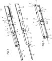
Fig. 4 zeigt beispielhaft zwei Ausziehführungen 20, mit denen ein bewegbares Möbelteil wie z.B. eine Schublade ein- uns ausziehbar in einem Möbelkorpus befestigt werden kann. Das gezeigte Beispiel der Ausziehführungen 12 ist derEP 2 074 909 B1 entnommen und dort im Detail beschrieben. Zum allgemeinen Aufbau einer Ausziehführung 12 sowie der dort realisierten Einzugsvorrichtung 17 wird auf diese Schrift verwiesen, deren Inhalt somit diesbezüglich Teil der Offenbarung dieser Erfindung ist. Im Gegensatz zurEP 2 074 909 B1 sind bei den Ausziehführungen gemäßFig. 4 nun aber Achsbolzen 2 und Rollen 3 einer Anordnung 1 mit zumindest einer Schmierschicht 4 aus Gleitlack 5 eingesetzt. Anordnungen 1 von Achsbolzen 2 und Rolle 3 mit einer Schmierschicht 4 in Form eines Gleitlackes 5 können natürlich auch bei ganz anders gestalteten Ausziehführungen 12 verwendet werden. - Im gezeigten Ausführungsbeispiel weist jedenfalls jede der Ausziehführungen 12 jeweils drei Schienen 13, 14 und 15 auf. Die drei Schienen 13, 14 und 15 der jeweiligen Ausziehführung 12 sind über die an ihnen angeordneten Rollen 3 in- bzw. aneinander verschiebbar gelagert. Bei der Schiene 15 handelt es sich um die sogenannte Ladenschiene, an der das bewegbare Möbelteil befestigt wird. Zur Montage im bzw. am Möbelkorpus ist die Schiene 13 in Form der sogenannten Korpusschiene vorgesehen. Die zwischen den beiden Schienen 13 und 15 angeordnete Schiene 14 wird als Mittelschiene bezeichnet. Im gezeigten Ausführungsbeispiel handelt es sich um einen sogenannten Vollauszug, bei dem das bewegliche Möbelteil bzw. die Schublade in Ausziehrichtung 18 vollständig aus dem Möbelkorpus herausgezogen werden kann. Zum Wiedereinschieben des bewegbaren Möbelteils in den hier nicht gezeigten Möbelkorpus wird das hier nicht gezeigte bewegliche Möbelteil samt der Schienen entgegen der Ausziehrichtung 18 bewegt. Dies ist an sich bekannt.
- Erfindungsgemäß werden bei diesen Ausziehführungen 12 nun Anordnungen 1 aus Achsbolzen 2 und Rolle 3 verwendet, bei denen zwischen dem Achsbolzen 2 und der Rolle 3 eine Schmierschicht 4 bestehend aus Gleitlack 5 angeordnet ist. Im gezeigten Ausführungsbeispiel werden ausschließlich erfindungsgemäße Anordnungen 1 aus Rolle 3 und Achsbolzen 2 verwendet. Natürlich kann die Erfindung auch nur für einzelne Anordnungen aus Rollen 3 und Achsbolzen 2 realisiert sein. Besonders günstig ist es, die Differentialrolle 20 als Teil einer erfindungsgemäßen Anordnung 1 auszubilden. Die Differentialrolle 20 sorgt, wie an sich bekannt, dafür, dass die Bewegung der Schienen 13, 14 und 15 relativ zueinander zwangsgekoppelt stattfindet. Das heißt, dass bei einer Bewegung der Schiene 15 die mittlere Schiene 14 zwangsweise ein entsprechendes Stück weit mit in Ausziehrichtung 18 herausgezogen oder in Gegenrichtung eingeschoben wird. Im gezeigten Ausführungsbeispiel ist, wie besonders gut in
Fig. 5 zu sehen, der die Differentialrolle 20 tragende Achsbolzen 2 an der mittleren Schiene 14 befestigt, während die Differentialrolle 20 mit ihrer Abrollfläche 16 sowohl an der Schiene 15 als auch an der Schiene 13 abrollt. Über entsprechende Reibungswerte und Andrückkräfte wird dafür gesorgt, dass dabei kein Schlupf vorhanden ist. Dies ist an sich bekannt und muss nicht weiter erläutert werden. Die erfindungsgemäße Verwendung des Gleitlackes 5 als Schmierschicht 4 verhindert eine Beeinträchtigung des Differentiallaufes durch heraustropfendes Öl oder dergleichen. -
- 1
- Anordnung
- 2
- Achsbolzen
- 3
- Rolle
- 4
- Schmierschicht
- 5
- Gleitlack
- 6
- Festschmierstoff
- 7
- Bindemittel
- 8
- Führungswand
- 9
- Führungswand
- 10
- Achsboizenaufnahme
- 11
- Rollenführungsfläche
- 12
- Ausziehführung
- 13
- Schiene
- 14
- Schiene
- 15
- Schiene
- 16
- Abrollfläche
- 17
- Einzugsvorrichtung
- 18
- Ausziehrichtung
- 19
- Achsbolzenaufnahmelauffläche
- 20
- Differentialrolle
- 21
- Befestigungsniete
- 22
- Rotationsachse
Claims (10)
- Ausziehführung (12) für bewegliche Möbelteile, insbesondere für Schubladen, mit zumindest zwei relativ zueinander verschiebbar in- oder aneinander gelagerten Schienen (13, 14, 15), wobei die Ausziehführung (12) zumindest eine Anordnung (1) mit zumindest einer auf einem Achsbolzen (2) drehbar gelagerten Rolle (3) aufweist, und der Achsbolzen (2) der zumindest einen Anordnung (1) an einer der Schienen (13, 14, 15) angeordnet ist, wobei zwischen dem Achsbolzen (2) und der Rolle (3) zumindest eine Schmierschicht (4) zur Herabsetzung der Reibung zwischen dem Achsbolzen (2) und der Rolle (3) angeordnet ist, dadurch gekennzeichnet, dass die Schmierschicht (4) aus einem Gleitlack (5) besteht.
- Ausziehführung (12) nach Anspruch 1, dadurch gekennzeichnet, dass der Gleitlack (5) zumindest einen Festschmierstoff (6) und zumindest ein, vorzugsweise ausgehärtetes, Bindemittel (7) aufweist.
- Ausziehführung (12) nach Anspruch 2, dadurch gekennzeichnet, dass der Gleitlack (5) zusätzlich zumindest ein Additiv zum Korrosionsschutz und/oder zur Konservierung aufweist.
- Ausziehführung (12) nach einem der Ansprüche 1 bis 3, dadurch gekennzeichnet, dass der Gleitlack (5) auf den Achsbolzen (2) aufgetragen, vorzugsweise auf diesem fixiert, ist.
- Ausziehführung (12) nach Anspruch 4, dadurch gekennzeichnet, dass der Gleitlack (5) auf zumindest einer Rollenführungsfläche (11) des Achsbolzens (2), auf der die Rolle (3) läuft, und/oder auf zumindest einer, die Rolle (3) seitlich führenden Führungswand (8, 9), vorzugsweise des Achsbolzens (2), aufgetragen, vorzugsweise fixiert, ist.
- Ausziehführung (12) nach einem der Ansprüche 1 bis 5, dadurch gekennzeichnet, dass der Gleitlack (5) auf der Rolle (3) aufgetragen, vorzugsweise fixiert, ist.
- Ausziehführung (12) nach einem der Ansprüche 1 bis 6, dadurch gekennzeichnet, dass die Rolle (3) und/oder der Achsbolzen (2) Kunststoff und/oder Gummi und/oder Metall, vorzugsweise Stahl, aufweist oder daraus besteht.
- Ausziehführung (12) nach einem der Ansprüche 1 bis 7, dadurch gekennzeichnet, dass der Achsbolzen (2) der zumindest einen Anordnung (1) an einer der Schienen (13, 14, 15) fixiert ist.
- Ausziehführung (12) nach einem der Ansprüche 1 bis 8, dadurch gekennzeichnet, dass die Rolle (3) der Anordnung (1) an zumindest einer der Schienen (13, 14, 15) reibschlüssig und/oder schlupffrei entlang rollbar ist.
- Ausziehführung (12) nach einem der Ansprüche 1 bis 9, dadurch gekennzeichnet, dass die Rolle (3) der Anordnung (1) eine Differentialrolle (20) zur Zwangskopplung der Bewegung von zumindest zwei Schienen (13, 14, 15) der Ausziehführung (12) ist.
Priority Applications (1)
| Application Number | Priority Date | Filing Date | Title |
|---|---|---|---|
| PL14825083T PL3094874T3 (pl) | 2014-01-14 | 2014-11-20 | Układ z co najmniej jedną rolką osadzoną obrotowo na sworzniu osiowym |
Applications Claiming Priority (2)
| Application Number | Priority Date | Filing Date | Title |
|---|---|---|---|
| ATGM13/2014U AT14099U1 (de) | 2014-01-14 | 2014-01-14 | Anordnung mit zumindest einer auf einem Achsbolzen drehbar gelagerten Rolle |
| PCT/AT2014/000206 WO2015106301A1 (de) | 2014-01-14 | 2014-11-20 | Anordnung mit zumindest einer auf einem achsbolzen drehbar gelagerten rolle |
Publications (2)
| Publication Number | Publication Date |
|---|---|
| EP3094874A1 EP3094874A1 (de) | 2016-11-23 |
| EP3094874B1 true EP3094874B1 (de) | 2018-06-27 |
Family
ID=52780679
Family Applications (1)
| Application Number | Title | Priority Date | Filing Date |
|---|---|---|---|
| EP14825083.0A Active EP3094874B1 (de) | 2014-01-14 | 2014-11-20 | Anordnung mit zumindest einer auf einem achsbolzen drehbar gelagerten rolle |
Country Status (4)
| Country | Link |
|---|---|
| EP (1) | EP3094874B1 (de) |
| AT (1) | AT14099U1 (de) |
| PL (1) | PL3094874T3 (de) |
| WO (1) | WO2015106301A1 (de) |
Families Citing this family (1)
| Publication number | Priority date | Publication date | Assignee | Title |
|---|---|---|---|---|
| CN114825063A (zh) * | 2022-04-14 | 2022-07-29 | 宁波立新科技股份有限公司 | 一种新型低压开关柜 |
Family Cites Families (7)
| Publication number | Priority date | Publication date | Assignee | Title |
|---|---|---|---|---|
| US2497224A (en) * | 1949-01-11 | 1950-02-14 | George R Laure | Plastic roller |
| US3215476A (en) * | 1963-04-22 | 1965-11-02 | Arthur W Jacobs | Cabinet roller assembly |
| JP4359066B2 (ja) * | 2003-04-14 | 2009-11-04 | 株式会社豊田自動織機 | 摺動部用塗料組成物 |
| JP2005024094A (ja) * | 2003-06-10 | 2005-01-27 | Ntn Corp | すべり軸受 |
| DE102005020438A1 (de) * | 2005-04-29 | 2006-11-02 | Gross + Froelich Gmbh & Co. Kg | Lenkrolle mit Zwillingsrädern |
| AT506062B1 (de) | 2007-12-27 | 2009-06-15 | Fulterer Gmbh | Rollen-ausziehführung |
| JP4932884B2 (ja) * | 2009-05-01 | 2012-05-16 | アクロス株式会社 | 摺動部材用被膜組成物 |
-
2014
- 2014-01-14 AT ATGM13/2014U patent/AT14099U1/de not_active IP Right Cessation
- 2014-11-20 WO PCT/AT2014/000206 patent/WO2015106301A1/de not_active Ceased
- 2014-11-20 PL PL14825083T patent/PL3094874T3/pl unknown
- 2014-11-20 EP EP14825083.0A patent/EP3094874B1/de active Active
Non-Patent Citations (1)
| Title |
|---|
| None * |
Also Published As
| Publication number | Publication date |
|---|---|
| PL3094874T3 (pl) | 2018-11-30 |
| EP3094874A1 (de) | 2016-11-23 |
| WO2015106301A1 (de) | 2015-07-23 |
| AT14099U1 (de) | 2015-04-15 |
Similar Documents
| Publication | Publication Date | Title |
|---|---|---|
| EP3071071B1 (de) | Dämpfungsvorrichtung | |
| EP3147239B1 (de) | Zahnriemen mit integrierten stützrollen | |
| WO2015150197A1 (de) | Führungssystem für versorgungsleitungen und roboter mit führungssystem | |
| AT509540A1 (de) | Ausziehführung für schubladen | |
| DE102004036529A1 (de) | Linearvorrichtung | |
| DE4227604A1 (de) | Waelzkontakt-linearfuehrungseinheit mit daempfungsmechanismus | |
| EP2872005A1 (de) | Auszugsführung | |
| EP3092919B1 (de) | Führungseinrichtung zur führung eines relativ zu einem möbelkorpus bewegbaren möbelteils | |
| EP3653821A1 (de) | Führungsvorrichtung | |
| DE102013113671A1 (de) | Führungsvorrichtung für linear bewegbare Bauteile | |
| EP1521712B1 (de) | Schmiereinrichtung zum abschmieren wandernder schmierstellen, wie solchen an einem band | |
| EP1140555B1 (de) | Schiene zur führung von laufschienen von kfz-komponenten und verfahren zu ihrer herstellung | |
| EP0780071A2 (de) | Schublade mit Rollen-Ausziehführung | |
| EP0300022B1 (de) | Ausziehführung | |
| DE102005014745A1 (de) | Gerade Führung und untere Abdichtung | |
| EP2979581B1 (de) | Führungseinrichtung zur führung eines relativ zu einem möbelkorpus bewegbaren möbelteils | |
| AT512897B1 (de) | Ausziehführung für ein aus einem Möbelkorpus ausziehbares Möbelteil | |
| WO2015106301A1 (de) | Anordnung mit zumindest einer auf einem achsbolzen drehbar gelagerten rolle | |
| EP3434144A1 (de) | Ausziehführung | |
| DE102006007978A1 (de) | Teleskopführung mit Rastelement | |
| EP4687586A1 (de) | Differenzialausziehführung | |
| EP2422099B1 (de) | Schmiervorrichtung und verfahren zur schmierung einer linearführung | |
| DE4412797A1 (de) | Lagerelement mit einer Schmiervorrichtung | |
| DE19911312B4 (de) | Ausziehführung | |
| DE102012216658A1 (de) | Lagerungsanordnung für eine verschiebbare hängende Einrichtung |
Legal Events
| Date | Code | Title | Description |
|---|---|---|---|
| PUAI | Public reference made under article 153(3) epc to a published international application that has entered the european phase |
Free format text: ORIGINAL CODE: 0009012 |
|
| 17P | Request for examination filed |
Effective date: 20160530 |
|
| AK | Designated contracting states |
Kind code of ref document: A1 Designated state(s): AL AT BE BG CH CY CZ DE DK EE ES FI FR GB GR HR HU IE IS IT LI LT LU LV MC MK MT NL NO PL PT RO RS SE SI SK SM TR |
|
| AX | Request for extension of the european patent |
Extension state: BA ME |
|
| DAX | Request for extension of the european patent (deleted) | ||
| RAP1 | Party data changed (applicant data changed or rights of an application transferred) |
Owner name: FULTERER AG & CO KG |
|
| GRAP | Despatch of communication of intention to grant a patent |
Free format text: ORIGINAL CODE: EPIDOSNIGR1 |
|
| INTG | Intention to grant announced |
Effective date: 20180319 |
|
| RIN1 | Information on inventor provided before grant (corrected) |
Inventor name: RAID, KARL |
|
| GRAS | Grant fee paid |
Free format text: ORIGINAL CODE: EPIDOSNIGR3 |
|
| GRAA | (expected) grant |
Free format text: ORIGINAL CODE: 0009210 |
|
| AK | Designated contracting states |
Kind code of ref document: B1 Designated state(s): AL AT BE BG CH CY CZ DE DK EE ES FI FR GB GR HR HU IE IS IT LI LT LU LV MC MK MT NL NO PL PT RO RS SE SI SK SM TR |
|
| REG | Reference to a national code |
Ref country code: GB Ref legal event code: FG4D Free format text: NOT ENGLISH |
|
| REG | Reference to a national code |
Ref country code: AT Ref legal event code: REF Ref document number: 1012613 Country of ref document: AT Kind code of ref document: T Effective date: 20180715 |
|
| REG | Reference to a national code |
Ref country code: IE Ref legal event code: FG4D Free format text: LANGUAGE OF EP DOCUMENT: GERMAN |
|
| REG | Reference to a national code |
Ref country code: DE Ref legal event code: R096 Ref document number: 502014008700 Country of ref document: DE |
|
| PG25 | Lapsed in a contracting state [announced via postgrant information from national office to epo] |
Ref country code: BG Free format text: LAPSE BECAUSE OF FAILURE TO SUBMIT A TRANSLATION OF THE DESCRIPTION OR TO PAY THE FEE WITHIN THE PRESCRIBED TIME-LIMIT Effective date: 20180927 Ref country code: FI Free format text: LAPSE BECAUSE OF FAILURE TO SUBMIT A TRANSLATION OF THE DESCRIPTION OR TO PAY THE FEE WITHIN THE PRESCRIBED TIME-LIMIT Effective date: 20180627 Ref country code: SE Free format text: LAPSE BECAUSE OF FAILURE TO SUBMIT A TRANSLATION OF THE DESCRIPTION OR TO PAY THE FEE WITHIN THE PRESCRIBED TIME-LIMIT Effective date: 20180627 Ref country code: NO Free format text: LAPSE BECAUSE OF FAILURE TO SUBMIT A TRANSLATION OF THE DESCRIPTION OR TO PAY THE FEE WITHIN THE PRESCRIBED TIME-LIMIT Effective date: 20180927 Ref country code: LT Free format text: LAPSE BECAUSE OF FAILURE TO SUBMIT A TRANSLATION OF THE DESCRIPTION OR TO PAY THE FEE WITHIN THE PRESCRIBED TIME-LIMIT Effective date: 20180627 |
|
| REG | Reference to a national code |
Ref country code: NL Ref legal event code: MP Effective date: 20180627 |
|
| REG | Reference to a national code |
Ref country code: LT Ref legal event code: MG4D |
|
| PG25 | Lapsed in a contracting state [announced via postgrant information from national office to epo] |
Ref country code: RS Free format text: LAPSE BECAUSE OF FAILURE TO SUBMIT A TRANSLATION OF THE DESCRIPTION OR TO PAY THE FEE WITHIN THE PRESCRIBED TIME-LIMIT Effective date: 20180627 Ref country code: HR Free format text: LAPSE BECAUSE OF FAILURE TO SUBMIT A TRANSLATION OF THE DESCRIPTION OR TO PAY THE FEE WITHIN THE PRESCRIBED TIME-LIMIT Effective date: 20180627 Ref country code: GR Free format text: LAPSE BECAUSE OF FAILURE TO SUBMIT A TRANSLATION OF THE DESCRIPTION OR TO PAY THE FEE WITHIN THE PRESCRIBED TIME-LIMIT Effective date: 20180928 Ref country code: LV Free format text: LAPSE BECAUSE OF FAILURE TO SUBMIT A TRANSLATION OF THE DESCRIPTION OR TO PAY THE FEE WITHIN THE PRESCRIBED TIME-LIMIT Effective date: 20180627 |
|
| PG25 | Lapsed in a contracting state [announced via postgrant information from national office to epo] |
Ref country code: NL Free format text: LAPSE BECAUSE OF FAILURE TO SUBMIT A TRANSLATION OF THE DESCRIPTION OR TO PAY THE FEE WITHIN THE PRESCRIBED TIME-LIMIT Effective date: 20180627 |
|
| PG25 | Lapsed in a contracting state [announced via postgrant information from national office to epo] |
Ref country code: EE Free format text: LAPSE BECAUSE OF FAILURE TO SUBMIT A TRANSLATION OF THE DESCRIPTION OR TO PAY THE FEE WITHIN THE PRESCRIBED TIME-LIMIT Effective date: 20180627 Ref country code: IS Free format text: LAPSE BECAUSE OF FAILURE TO SUBMIT A TRANSLATION OF THE DESCRIPTION OR TO PAY THE FEE WITHIN THE PRESCRIBED TIME-LIMIT Effective date: 20181027 Ref country code: RO Free format text: LAPSE BECAUSE OF FAILURE TO SUBMIT A TRANSLATION OF THE DESCRIPTION OR TO PAY THE FEE WITHIN THE PRESCRIBED TIME-LIMIT Effective date: 20180627 |
|
| PG25 | Lapsed in a contracting state [announced via postgrant information from national office to epo] |
Ref country code: SM Free format text: LAPSE BECAUSE OF FAILURE TO SUBMIT A TRANSLATION OF THE DESCRIPTION OR TO PAY THE FEE WITHIN THE PRESCRIBED TIME-LIMIT Effective date: 20180627 Ref country code: ES Free format text: LAPSE BECAUSE OF FAILURE TO SUBMIT A TRANSLATION OF THE DESCRIPTION OR TO PAY THE FEE WITHIN THE PRESCRIBED TIME-LIMIT Effective date: 20180627 |
|
| REG | Reference to a national code |
Ref country code: DE Ref legal event code: R097 Ref document number: 502014008700 Country of ref document: DE |
|
| PLBE | No opposition filed within time limit |
Free format text: ORIGINAL CODE: 0009261 |
|
| STAA | Information on the status of an ep patent application or granted ep patent |
Free format text: STATUS: NO OPPOSITION FILED WITHIN TIME LIMIT |
|
| PG25 | Lapsed in a contracting state [announced via postgrant information from national office to epo] |
Ref country code: DK Free format text: LAPSE BECAUSE OF FAILURE TO SUBMIT A TRANSLATION OF THE DESCRIPTION OR TO PAY THE FEE WITHIN THE PRESCRIBED TIME-LIMIT Effective date: 20180627 |
|
| 26N | No opposition filed |
Effective date: 20190328 |
|
| GBPC | Gb: european patent ceased through non-payment of renewal fee |
Effective date: 20181120 |
|
| PG25 | Lapsed in a contracting state [announced via postgrant information from national office to epo] |
Ref country code: LU Free format text: LAPSE BECAUSE OF NON-PAYMENT OF DUE FEES Effective date: 20181120 Ref country code: MC Free format text: LAPSE BECAUSE OF FAILURE TO SUBMIT A TRANSLATION OF THE DESCRIPTION OR TO PAY THE FEE WITHIN THE PRESCRIBED TIME-LIMIT Effective date: 20180627 |
|
| REG | Reference to a national code |
Ref country code: BE Ref legal event code: MM Effective date: 20181130 |
|
| REG | Reference to a national code |
Ref country code: IE Ref legal event code: MM4A |
|
| PG25 | Lapsed in a contracting state [announced via postgrant information from national office to epo] |
Ref country code: SI Free format text: LAPSE BECAUSE OF FAILURE TO SUBMIT A TRANSLATION OF THE DESCRIPTION OR TO PAY THE FEE WITHIN THE PRESCRIBED TIME-LIMIT Effective date: 20180627 |
|
| PG25 | Lapsed in a contracting state [announced via postgrant information from national office to epo] |
Ref country code: FR Free format text: LAPSE BECAUSE OF NON-PAYMENT OF DUE FEES Effective date: 20181130 Ref country code: IE Free format text: LAPSE BECAUSE OF NON-PAYMENT OF DUE FEES Effective date: 20181120 |
|
| PG25 | Lapsed in a contracting state [announced via postgrant information from national office to epo] |
Ref country code: AL Free format text: LAPSE BECAUSE OF FAILURE TO SUBMIT A TRANSLATION OF THE DESCRIPTION OR TO PAY THE FEE WITHIN THE PRESCRIBED TIME-LIMIT Effective date: 20180627 Ref country code: BE Free format text: LAPSE BECAUSE OF NON-PAYMENT OF DUE FEES Effective date: 20181130 |
|
| PG25 | Lapsed in a contracting state [announced via postgrant information from national office to epo] |
Ref country code: GB Free format text: LAPSE BECAUSE OF NON-PAYMENT OF DUE FEES Effective date: 20181120 |
|
| PG25 | Lapsed in a contracting state [announced via postgrant information from national office to epo] |
Ref country code: MT Free format text: LAPSE BECAUSE OF FAILURE TO SUBMIT A TRANSLATION OF THE DESCRIPTION OR TO PAY THE FEE WITHIN THE PRESCRIBED TIME-LIMIT Effective date: 20180627 |
|
| PGFP | Annual fee paid to national office [announced via postgrant information from national office to epo] |
Ref country code: SK Payment date: 20191115 Year of fee payment: 6 |
|
| PGFP | Annual fee paid to national office [announced via postgrant information from national office to epo] |
Ref country code: PL Payment date: 20191029 Year of fee payment: 6 |
|
| PG25 | Lapsed in a contracting state [announced via postgrant information from national office to epo] |
Ref country code: TR Free format text: LAPSE BECAUSE OF FAILURE TO SUBMIT A TRANSLATION OF THE DESCRIPTION OR TO PAY THE FEE WITHIN THE PRESCRIBED TIME-LIMIT Effective date: 20180627 |
|
| PG25 | Lapsed in a contracting state [announced via postgrant information from national office to epo] |
Ref country code: PT Free format text: LAPSE BECAUSE OF FAILURE TO SUBMIT A TRANSLATION OF THE DESCRIPTION OR TO PAY THE FEE WITHIN THE PRESCRIBED TIME-LIMIT Effective date: 20180627 |
|
| PG25 | Lapsed in a contracting state [announced via postgrant information from national office to epo] |
Ref country code: CY Free format text: LAPSE BECAUSE OF FAILURE TO SUBMIT A TRANSLATION OF THE DESCRIPTION OR TO PAY THE FEE WITHIN THE PRESCRIBED TIME-LIMIT Effective date: 20180627 Ref country code: HU Free format text: LAPSE BECAUSE OF FAILURE TO SUBMIT A TRANSLATION OF THE DESCRIPTION OR TO PAY THE FEE WITHIN THE PRESCRIBED TIME-LIMIT; INVALID AB INITIO Effective date: 20141120 Ref country code: MK Free format text: LAPSE BECAUSE OF NON-PAYMENT OF DUE FEES Effective date: 20180627 |
|
| REG | Reference to a national code |
Ref country code: SK Ref legal event code: MM4A Ref document number: E 28329 Country of ref document: SK Effective date: 20201120 |
|
| PG25 | Lapsed in a contracting state [announced via postgrant information from national office to epo] |
Ref country code: SK Free format text: LAPSE BECAUSE OF NON-PAYMENT OF DUE FEES Effective date: 20201120 |
|
| REG | Reference to a national code |
Ref country code: DE Ref legal event code: R082 Ref document number: 502014008700 Country of ref document: DE Representative=s name: VKK PATENTANWAELTE PARTG MBB, DE |
|
| PG25 | Lapsed in a contracting state [announced via postgrant information from national office to epo] |
Ref country code: PL Free format text: LAPSE BECAUSE OF NON-PAYMENT OF DUE FEES Effective date: 20201120 |
|
| P01 | Opt-out of the competence of the unified patent court (upc) registered |
Effective date: 20230514 |
|
| REG | Reference to a national code |
Ref country code: CH Ref legal event code: U11 Free format text: ST27 STATUS EVENT CODE: U-0-0-U10-U11 (AS PROVIDED BY THE NATIONAL OFFICE) Effective date: 20251201 |
|
| PGFP | Annual fee paid to national office [announced via postgrant information from national office to epo] |
Ref country code: DE Payment date: 20251118 Year of fee payment: 12 |
|
| PGFP | Annual fee paid to national office [announced via postgrant information from national office to epo] |
Ref country code: AT Payment date: 20251117 Year of fee payment: 12 |
|
| PGFP | Annual fee paid to national office [announced via postgrant information from national office to epo] |
Ref country code: IT Payment date: 20251128 Year of fee payment: 12 |
|
| PGFP | Annual fee paid to national office [announced via postgrant information from national office to epo] |
Ref country code: CH Payment date: 20251201 Year of fee payment: 12 |
|
| PGFP | Annual fee paid to national office [announced via postgrant information from national office to epo] |
Ref country code: CZ Payment date: 20251107 Year of fee payment: 12 |