EP3094834B1 - Systeme d'aspiration d'huile pour moteur a explosion comportant au moins un cylindre horizontal ou incliné sous le plan horizontal - Google Patents
Systeme d'aspiration d'huile pour moteur a explosion comportant au moins un cylindre horizontal ou incliné sous le plan horizontal Download PDFInfo
- Publication number
- EP3094834B1 EP3094834B1 EP15702535.4A EP15702535A EP3094834B1 EP 3094834 B1 EP3094834 B1 EP 3094834B1 EP 15702535 A EP15702535 A EP 15702535A EP 3094834 B1 EP3094834 B1 EP 3094834B1
- Authority
- EP
- European Patent Office
- Prior art keywords
- cylinder head
- pump
- internal combustion
- combustion engine
- engine according
- Prior art date
- Legal status (The legal status is an assumption and is not a legal conclusion. Google has not performed a legal analysis and makes no representation as to the accuracy of the status listed.)
- Active
Links
Images


Classifications
-
- F—MECHANICAL ENGINEERING; LIGHTING; HEATING; WEAPONS; BLASTING
- F01—MACHINES OR ENGINES IN GENERAL; ENGINE PLANTS IN GENERAL; STEAM ENGINES
- F01M—LUBRICATING OF MACHINES OR ENGINES IN GENERAL; LUBRICATING INTERNAL COMBUSTION ENGINES; CRANKCASE VENTILATING
- F01M1/00—Pressure lubrication
- F01M1/02—Pressure lubrication using lubricating pumps
-
- F—MECHANICAL ENGINEERING; LIGHTING; HEATING; WEAPONS; BLASTING
- F01—MACHINES OR ENGINES IN GENERAL; ENGINE PLANTS IN GENERAL; STEAM ENGINES
- F01M—LUBRICATING OF MACHINES OR ENGINES IN GENERAL; LUBRICATING INTERNAL COMBUSTION ENGINES; CRANKCASE VENTILATING
- F01M11/00—Component parts, details or accessories, not provided for in, or of interest apart from, groups F01M1/00 - F01M9/00
-
- F—MECHANICAL ENGINEERING; LIGHTING; HEATING; WEAPONS; BLASTING
- F01—MACHINES OR ENGINES IN GENERAL; ENGINE PLANTS IN GENERAL; STEAM ENGINES
- F01M—LUBRICATING OF MACHINES OR ENGINES IN GENERAL; LUBRICATING INTERNAL COMBUSTION ENGINES; CRANKCASE VENTILATING
- F01M1/00—Pressure lubrication
- F01M1/02—Pressure lubrication using lubricating pumps
- F01M2001/0253—Pressure lubrication using lubricating pumps characterised by the pump driving means
- F01M2001/0261—Pressure lubrication using lubricating pumps characterised by the pump driving means driven by the camshaft
-
- F—MECHANICAL ENGINEERING; LIGHTING; HEATING; WEAPONS; BLASTING
- F01—MACHINES OR ENGINES IN GENERAL; ENGINE PLANTS IN GENERAL; STEAM ENGINES
- F01M—LUBRICATING OF MACHINES OR ENGINES IN GENERAL; LUBRICATING INTERNAL COMBUSTION ENGINES; CRANKCASE VENTILATING
- F01M1/00—Pressure lubrication
- F01M1/02—Pressure lubrication using lubricating pumps
- F01M2001/0284—Pressure lubrication using lubricating pumps mounting of the pump
Definitions
- the present invention relates to the field of explosion engines, and more particularly to engines whose cylinders are horizontal or inclined under the horizontal plane.
- This situation can result either from the architecture of the vehicle (for example a car engine with flat cylinders, or a motorcycle of the "flattwin” type), or from its use (for example a particular aerobatic plane, or a motorcycle on a stand).
- the cylinder head is the upper part, most often removable, a reciprocating piston engine. She closes the top of the cylinders. On some engines, the intake and exhaust valves are housed. Its shape and characteristics are always closely linked to the evolution of the engines and are more particularly determined according to the type of distribution and the shape of the combustion chamber.
- German patent application DE 4424248 describing a "flat-six" flatbed motor with a gear pump for emptying the cylinder head.
- the problem of the prior art is that when the cylinder head is in an inclined or horizontal position, the oil stagnates in the lower part of the cylinder head. Due to the high temperature of the cylinder head, the oil level rises in the cylinder head creating a bubbling and infiltration of oil through the valves creating fumes.
- the present invention relates, in its most general sense, to an explosion engine comprising at least one cylinder inclined under the horizontal plane, comprising a cylinder head provided with lubricating means, and a distribution system, characterized in that said cylinder head comprises an oil return pump sucking the oil into the low point of the cylinder head cover and driving the oil towards the main casing of the engine.
- said pump is driven by the dispensing system.
- the body of the pump is machined in the cylinder head and closed by a lid.
- the body of the pump opens into a suction bore.
- said pump is a trochoidal pump.
- the invention preferably relates to a twin-cylinder engine whose cylinders are opposite and arranged longitudinally with respect to the vehicle, in particular a motorcycle.
- the cylinders are inclined relative to the horizontal plane at an angle of about 25 °.
- One of the cylinders is inclined downwards, the other by the top.
- Lubricating oil has a tendency to accumulate in the lower head of the bolt, and must be evacuated.
- the evacuation is done by gravity.
- the evacuation can be done by gravity or with a pump.
- the oil of the crankcase can go up through the evacuation tubes towards the cylinder head, which is not appropriate.
- the figure 1 represents a view of the cylinder head (1) and the cylinder (2).
- the cylinder head (1) is shown without its upper half-bearing or the pump.
- the cylinder head has an exhaust cam shaft (3) and an intake cam shaft (4).
- the yoke (1) has at its end an extension (5) on which is applied the half-bearing (6) shown in FIG. figure 2 .
- the pump body (7) is formed by machining for a first semi-cylindrical part (8) in the extension (5) and a second semi-cylindrical portion (9) machined in half-bearing (6).
- the inner (10) and outer (11) rotors are housed in the pump body (7).
- the inner rotor (10) is carried by the camshaft end (12) and driven by the pin (13).
- a cover (14) closes the pump. It has on its inner surface an intake pocket (15) and an exhaust pocket (16).
- the oil is drawn from an orifice (17) connecting the draw zone (18) located in the lowest part of the cylinder head to a cylinder head inlet pocket (19) communicating with the air bag. inlet (15) of the lid, supplying the pump.
- the oil is sucked between the inner rotor (10) and the outer rotor (11) and pushed into the pocket (16).
- This pocket (16) communicates with the pocket (20) to be then rejected in a drilling system oriented along the axis (21), into the main housing of the engine.
Landscapes
- Engineering & Computer Science (AREA)
- Mechanical Engineering (AREA)
- General Engineering & Computer Science (AREA)
- Lubrication Of Internal Combustion Engines (AREA)
- Lubrication Details And Ventilation Of Internal Combustion Engines (AREA)
- Cylinder Crankcases Of Internal Combustion Engines (AREA)
Description
- La présente invention concerne le domaine des moteurs à explosions, et plus particulièrement les moteurs dont les cylindres sont horizontaux ou inclinés sous le plan horizontal. Cette situation peut résulter soit de l'architecture du véhicule (par exemple un moteur de voiture avec des cylindres à plat, ou une motocyclette de type « flattwin »), soit de son utilisation (par exemple un avion notamment de voltige, ou une motocyclette béquillée).
- La culasse est la partie supérieure, le plus souvent démontable, d'un moteur à pistons alternatifs. Elle ferme le haut des cylindres. Sur certains moteurs, les soupapes d'admission et d'échappement y sont logées. Sa forme et ses caractéristiques sont toujours étroitement liées à l'évolution des moteurs et sont plus particulièrement déterminées en fonction du type de distribution et de la forme de la chambre de combustion.
- On connaît dans l'état de la technique la demande de brevet allemand
DE 4424248 décrivant un moteur à plat de type « flat-six » avec une pompe à engrenage pour le vidage de la culasse. - D'autres documents tels que les demandes
DE102008014828 ,DE2020100123697 JP S60192820 JP H08100614 DE4007939 décrivent différentes solutions de vidage de la culasse. - Le problème de l'art antérieur est que lorsque la culasse se trouve en position inclinée ou horizontale, l'huile stagne dans la partie basse de la culasse. En raison de la température élevée de la culasse, le niveau d'huile monte dans la culasse créant un barbotage et une infiltration d'huile au travers des soupapes créant des fumées.
- En particulier, pour des moteurs présentant un cylindre incliné sous l'horizontale et orienté longitudinalement, une problématique particulière se pose du fait des transferts intempestifs d'huile se produisant lors des freinages brutaux ou des accélérations puissantes.
- Afin de remédier à ces inconvénients, la présente invention concerne selon son acception la plus générale un moteur à explosion comportant au moins un cylindre incliné sous le plan horizontal, comportant une culasse muni de moyens de graissage, et un système de distribution, caractérisé en ce que ladite culasse comporte une pompe de retour d'huile aspirant l'huile dans le point bas du couvre-culasse et refoulant l'huile vers le carter principal du moteur.
- Avantageusement, ladite pompe est entraînée par le système de distribution.
- De préférence, le corps de la pompe est usiné dans la culasse et fermé par un couvercle.
- Selon un mode de mise en oeuvre particulier, le corps de la pompe débouche dans un forage d'aspiration.
- Avantageusement, ladite pompe est une pompe trochoïdale.
- La présente invention sera mieux comprise à la lecture de la description qui suit, concernant un exemple non limitatif de réalisation se référant aux dessins annexés où :
- la
figure 1 représente une vue de trois-quarts avant de la culasse d'un moteur ouverte - la
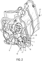
figure 2 représente une vue de trois-quarts avant de la culasse d'un moteur avec le rotor de la pompe sans couvre culasse ni couvercle de pompe - la
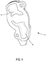
figure 3 représente une vue de trois-quarts avant de la culasse sans couvre culasse avec son couvercle de pompe dont lafigure 4 représente une vue de derrière. - L'invention concerne de préférence un moteur bicylindre dont les cylindres sont opposés et disposés longitudinalement par rapport au véhicule, notamment une motocyclette. Les cylindres sont inclinés par rapport au plan horizontal, d'un angle d'environ 25°. L'un des cylindres est incliné vers le bas, l'autre par le haut.
- L'huile de graissage a tendance à s'accumuler dans la tête de culasse basse, et doit être évacuée. Pour un moteur vertical, l'évacuation se fait par gravité. Pour un moteur horizontal ou incliné, l'évacuation peut se faire par gravité ou avec une pompe. Lors du freinage et dans le cas d'un retour par gravité, l'huile du carter moteur peut remonter par les tubes d'évacuation vers la culasse, ce qui n'est pas approprié.
- La
figure 1 représente une vue de la culasse (1) et du cylindre (2). La culasse (1) est représentée sans son demi-palier supérieur ni la pompe. - La culasse présente un arbre à came d'échappement (3) et un arbre à came d'admission (4).
- La culasse (1) présente à son extrémité un prolongement (5) sur lequel vient s'appliquer le demi-palier (6) représenté en
figure 2 . - Le corps de pompe (7) est formé par un usinage réalisé pour une première partie semi-cylindrique (8) dans le prolongement (5) et une deuxième partie semi-cylindrique (9) usinée dans demi-palier (6).
- Les rotors intérieur (10) et extérieur (11) sont logés dans le corps de pompe (7). Le rotor intérieur (10) est porté par le bout d'arbre à came (12) et entraîné par la goupille (13).
- Un capot (14) referme la pompe. Il présente à sa surface intérieure une poche d'admission (15) et une poche d'échappement (16). L'aspiration d'huile se fait à partir d'un orifice (17) reliant la zone de puisage (18) située dans la partie la plus basse de la culasse à une poche d'admission culasse (19) communiquant avec la poche d'admission (15) du couvercle, alimentant la pompe.
- L'huile est aspirée entre le rotor intérieur (10) et le rotor extérieur (11) et refoulé dans la poche (16). Cette poche (16) communique avec la poche (20) pour être ensuite rejetée dans un système de forages orientés selon l'axe (21), jusque dans le carter principal du moteur.
Claims (9)
- Moteur à explosion bicylindre pour motocyclette dont les cylindres sont opposés et disposés longitudinalement par rapport la motocyclette, comportant au moins un cylindre incliné sous le plan horizontal, comportant une culasse (1) muni de moyens de graissage, et un système de distribution comprenant un arbre à came, ladite culasse (1) comportant une pompe de retour d'huile aspirant l'huile dans le point bas du couvre-culasse (18) et refoulant l'huile vers le carter principal du moteur,
caractérisé en ce que le corps de pompe (7) comprend deux rotors intérieur (10) et extérieur (11), le rotor intérieur (10) étant porté par le bout d'arbre à came (12) et le capot (14) refermant la pompe et présentant à sa surface intérieure une poche d'admission (15) et une poche d'échappement (16). - Moteur à explosion selon la revendication principale, dans lequel le corps (7) de la pompe est usiné dans la culasse et fermé par un couvercle.
- Moteur à explosion selon la revendication précédente, dans lequel le corps de pompe (7) est formé par un usinage réalisé pour une première partie semi-cylindrique (8) dans un prolongement (5) de la culasse (1) et une deuxième partie semi-cylindrique (9) usinée dans un demi-palier (6) de la culasse (1).
- Moteur à explosion selon la revendication principale, dans lequel ladite pompe est une pompe trochoïdale.
- Moteur à explosion selon la revendication précédente, dans lequel le corps (7) de la pompe débouche dans un forage d'aspiration.
- Moteur à explosion selon l'une quelconque des revendications précédentes, dans lequel le corps de pompe (7) est formé par un usinage réalisé pour une première partie semi-cylindrique (8) dans le prolongement (5) et une deuxième partie semi-cylindrique (9) usinée dans demi-palier (6).
- Moteur à explosion selon la revendication précédente, comportant en outre un orifice (17) reliant la zone de puisage (18) située dans la partie la plus basse de la culasse à une poche d'admission culasse (19) communiquant avec la poche d'admission (15) du couvercle, alimentant la pompe.
- Motocyclette comportant un moteur à explosion bicylindre selon l'une quelconque des revendications précédentes, dont les cylindres sont opposés et disposés longitudinalement par rapport à ladite motocyclette.
- Moteur selon la revendication précédente, dans lequel les cylindres sont inclinés par rapport au plan horizontal, d'un angle d'environ 25°.
Applications Claiming Priority (2)
| Application Number | Priority Date | Filing Date | Title |
|---|---|---|---|
| FR1450241A FR3016403B1 (fr) | 2014-01-13 | 2014-01-13 | Systeme d'aspiration d'huile pour moteur a explosion comportant au moins un cylindre horizontal ou incline |
| PCT/FR2015/050029 WO2015104498A1 (fr) | 2014-01-13 | 2015-01-08 | Systeme d'aspiration d'huile pour moteur a explosion comportant au moins un cylindre horizontal ou incliné sous le plan horizontal |
Publications (2)
| Publication Number | Publication Date |
|---|---|
| EP3094834A1 EP3094834A1 (fr) | 2016-11-23 |
| EP3094834B1 true EP3094834B1 (fr) | 2019-11-27 |
Family
ID=50729608
Family Applications (1)
| Application Number | Title | Priority Date | Filing Date |
|---|---|---|---|
| EP15702535.4A Active EP3094834B1 (fr) | 2014-01-13 | 2015-01-08 | Systeme d'aspiration d'huile pour moteur a explosion comportant au moins un cylindre horizontal ou incliné sous le plan horizontal |
Country Status (5)
| Country | Link |
|---|---|
| EP (1) | EP3094834B1 (fr) |
| JP (1) | JP6539853B2 (fr) |
| CN (1) | CN106030058A (fr) |
| FR (1) | FR3016403B1 (fr) |
| WO (1) | WO2015104498A1 (fr) |
Family Cites Families (8)
| Publication number | Priority date | Publication date | Assignee | Title |
|---|---|---|---|---|
| JPH0680289B2 (ja) * | 1984-03-14 | 1994-10-12 | ヤマハ発動機株式会社 | 自動二輪車用エンジンの潤滑装置 |
| JPH0169105U (fr) * | 1987-10-27 | 1989-05-08 | ||
| DE4007939C1 (en) * | 1990-03-13 | 1991-08-08 | Mercedes-Benz Aktiengesellschaft, 7000 Stuttgart, De | Oil return system from IC engine cylinder head to sump - has oil return line completely outside engine block, and collector on cylinder head casing outside |
| DE4424248C1 (de) * | 1994-07-09 | 1995-12-07 | Porsche Ag | Brennkraftmaschine mit zwei gegen die Vertikale geneigten Zylinderbänken |
| JP3194179B2 (ja) * | 1994-09-30 | 2001-07-30 | スズキ株式会社 | 船外機のオイルポンプ装置 |
| DE102008014828A1 (de) * | 2008-03-18 | 2009-09-24 | Dr. Ing. H.C. F. Porsche Aktiengesellschaft | Brennkraftmaschine |
| DE102009042290B4 (de) * | 2009-09-19 | 2012-03-01 | Reinhart Fenske | Zweitakt-Verbrennungsmotor der Boxerbauart |
| CN202832714U (zh) * | 2012-09-14 | 2013-03-27 | 长城汽车股份有限公司 | 一种汽车发动机油气分离系统回油结构 |
-
2014
- 2014-01-13 FR FR1450241A patent/FR3016403B1/fr active Active
-
2015
- 2015-01-08 JP JP2016563266A patent/JP6539853B2/ja active Active
- 2015-01-08 CN CN201580008837.3A patent/CN106030058A/zh active Pending
- 2015-01-08 EP EP15702535.4A patent/EP3094834B1/fr active Active
- 2015-01-08 WO PCT/FR2015/050029 patent/WO2015104498A1/fr not_active Ceased
Non-Patent Citations (1)
| Title |
|---|
| None * |
Also Published As
| Publication number | Publication date |
|---|---|
| FR3016403B1 (fr) | 2018-10-12 |
| WO2015104498A1 (fr) | 2015-07-16 |
| EP3094834A1 (fr) | 2016-11-23 |
| CN106030058A (zh) | 2016-10-12 |
| JP6539853B2 (ja) | 2019-07-10 |
| JP2017502211A (ja) | 2017-01-19 |
| FR3016403A1 (fr) | 2015-07-17 |
Similar Documents
| Publication | Publication Date | Title |
|---|---|---|
| JP2007009919A (ja) | 自動二輪車用オイルポンプ | |
| JP2013130129A (ja) | エンジンのピストンの冷却構造 | |
| WO2015104498A1 (fr) | Systeme d'aspiration d'huile pour moteur a explosion comportant au moins un cylindre horizontal ou incliné sous le plan horizontal | |
| FR3020302A3 (fr) | Tronconneuse | |
| FR2973071A1 (fr) | Decanteur comportant un canal de refroidissement | |
| EP1529935A1 (fr) | Gicleur de refroidissement de piston à entre-axe réduit | |
| FR3078749A1 (fr) | Coussinet de palier de vilebrequin et systeme de lubrification associe | |
| EP2463488B1 (fr) | Structure de fixation pour pompe à vide | |
| FR3067386B1 (fr) | Machine de detente | |
| FR2549162A1 (fr) | Pompe a vide | |
| EP3631375B1 (fr) | Moteur comportant un dispositif de mesure pour moteur a combustion interne comprenant un detecteur de passage d'une cible | |
| EP3094832B1 (fr) | Moteur à explosion comportant des augets de graissage des cames | |
| FR3040459A1 (fr) | Bielle pour machine comprenant un piston et un vilebrequin | |
| US9057294B2 (en) | Engine provided with lubricating structure | |
| CA2616246A1 (fr) | Moteur thermique a piston de travail double effet, solidaire d'un piston de precompression double effet | |
| FR3055387B1 (fr) | Ensemble piston bielle rotulee avec augmentation de vitesse d’un flux d’huile interne | |
| FR2917121A1 (fr) | Dispositif et procede de lubrification,de refroidissement et d'amelioration du rendement des moteurs a pistons alternatifs | |
| WO2014044772A1 (fr) | Ensemble de production d'électricité à moteur à pression de vapeur | |
| FR3055386A1 (fr) | Ensemble piston bielle rotulee avec passage d’huile dans une rainure circulaire autour du piston | |
| FR3016393A1 (fr) | Moteur a explosion comportant un systeme de graissage a carter sec | |
| FR3055657A1 (fr) | Ensemble bielle et piston comprenant un percage d’amenee d’huile de lubrification dans une jupe de piston | |
| FR2608691A3 (fr) | Pompe a vide rotative a palettes perfectionnee | |
| EP1963630A2 (fr) | Moteur thermique compact | |
| FR2907842A3 (fr) | Moteur a combustion interne pour vehicule automobile a reserve d'huile delocalisee | |
| FR3051876A1 (fr) | Machine a piston a liaison rotule |
Legal Events
| Date | Code | Title | Description |
|---|---|---|---|
| PUAI | Public reference made under article 153(3) epc to a published international application that has entered the european phase |
Free format text: ORIGINAL CODE: 0009012 |
|
| 17P | Request for examination filed |
Effective date: 20160707 |
|
| AK | Designated contracting states |
Kind code of ref document: A1 Designated state(s): AL AT BE BG CH CY CZ DE DK EE ES FI FR GB GR HR HU IE IS IT LI LT LU LV MC MK MT NL NO PL PT RO RS SE SI SK SM TR |
|
| AX | Request for extension of the european patent |
Extension state: BA ME |
|
| DAX | Request for extension of the european patent (deleted) | ||
| STAA | Information on the status of an ep patent application or granted ep patent |
Free format text: STATUS: EXAMINATION IS IN PROGRESS |
|
| 17Q | First examination report despatched |
Effective date: 20180105 |
|
| GRAP | Despatch of communication of intention to grant a patent |
Free format text: ORIGINAL CODE: EPIDOSNIGR1 |
|
| STAA | Information on the status of an ep patent application or granted ep patent |
Free format text: STATUS: GRANT OF PATENT IS INTENDED |
|
| INTG | Intention to grant announced |
Effective date: 20190723 |
|
| GRAS | Grant fee paid |
Free format text: ORIGINAL CODE: EPIDOSNIGR3 |
|
| RAP1 | Party data changed (applicant data changed or rights of an application transferred) |
Owner name: RDMO |
|
| GRAA | (expected) grant |
Free format text: ORIGINAL CODE: 0009210 |
|
| STAA | Information on the status of an ep patent application or granted ep patent |
Free format text: STATUS: THE PATENT HAS BEEN GRANTED |
|
| AK | Designated contracting states |
Kind code of ref document: B1 Designated state(s): AL AT BE BG CH CY CZ DE DK EE ES FI FR GB GR HR HU IE IS IT LI LT LU LV MC MK MT NL NO PL PT RO RS SE SI SK SM TR |
|
| REG | Reference to a national code |
Ref country code: GB Ref legal event code: FG4D Free format text: NOT ENGLISH |
|
| REG | Reference to a national code |
Ref country code: CH Ref legal event code: EP |
|
| REG | Reference to a national code |
Ref country code: AT Ref legal event code: REF Ref document number: 1206886 Country of ref document: AT Kind code of ref document: T Effective date: 20191215 |
|
| REG | Reference to a national code |
Ref country code: DE Ref legal event code: R096 Ref document number: 602015042442 Country of ref document: DE |
|
| REG | Reference to a national code |
Ref country code: IE Ref legal event code: FG4D Free format text: LANGUAGE OF EP DOCUMENT: FRENCH |
|
| REG | Reference to a national code |
Ref country code: NL Ref legal event code: MP Effective date: 20191127 |
|
| REG | Reference to a national code |
Ref country code: LT Ref legal event code: MG4D |
|
| PG25 | Lapsed in a contracting state [announced via postgrant information from national office to epo] |
Ref country code: NL Free format text: LAPSE BECAUSE OF FAILURE TO SUBMIT A TRANSLATION OF THE DESCRIPTION OR TO PAY THE FEE WITHIN THE PRESCRIBED TIME-LIMIT Effective date: 20191127 Ref country code: FI Free format text: LAPSE BECAUSE OF FAILURE TO SUBMIT A TRANSLATION OF THE DESCRIPTION OR TO PAY THE FEE WITHIN THE PRESCRIBED TIME-LIMIT Effective date: 20191127 Ref country code: BG Free format text: LAPSE BECAUSE OF FAILURE TO SUBMIT A TRANSLATION OF THE DESCRIPTION OR TO PAY THE FEE WITHIN THE PRESCRIBED TIME-LIMIT Effective date: 20200227 Ref country code: NO Free format text: LAPSE BECAUSE OF FAILURE TO SUBMIT A TRANSLATION OF THE DESCRIPTION OR TO PAY THE FEE WITHIN THE PRESCRIBED TIME-LIMIT Effective date: 20200227 Ref country code: GR Free format text: LAPSE BECAUSE OF FAILURE TO SUBMIT A TRANSLATION OF THE DESCRIPTION OR TO PAY THE FEE WITHIN THE PRESCRIBED TIME-LIMIT Effective date: 20200228 Ref country code: LT Free format text: LAPSE BECAUSE OF FAILURE TO SUBMIT A TRANSLATION OF THE DESCRIPTION OR TO PAY THE FEE WITHIN THE PRESCRIBED TIME-LIMIT Effective date: 20191127 Ref country code: LV Free format text: LAPSE BECAUSE OF FAILURE TO SUBMIT A TRANSLATION OF THE DESCRIPTION OR TO PAY THE FEE WITHIN THE PRESCRIBED TIME-LIMIT Effective date: 20191127 Ref country code: SE Free format text: LAPSE BECAUSE OF FAILURE TO SUBMIT A TRANSLATION OF THE DESCRIPTION OR TO PAY THE FEE WITHIN THE PRESCRIBED TIME-LIMIT Effective date: 20191127 |
|
| PG25 | Lapsed in a contracting state [announced via postgrant information from national office to epo] |
Ref country code: HR Free format text: LAPSE BECAUSE OF FAILURE TO SUBMIT A TRANSLATION OF THE DESCRIPTION OR TO PAY THE FEE WITHIN THE PRESCRIBED TIME-LIMIT Effective date: 20191127 Ref country code: RS Free format text: LAPSE BECAUSE OF FAILURE TO SUBMIT A TRANSLATION OF THE DESCRIPTION OR TO PAY THE FEE WITHIN THE PRESCRIBED TIME-LIMIT Effective date: 20191127 Ref country code: IS Free format text: LAPSE BECAUSE OF FAILURE TO SUBMIT A TRANSLATION OF THE DESCRIPTION OR TO PAY THE FEE WITHIN THE PRESCRIBED TIME-LIMIT Effective date: 20200327 |
|
| PG25 | Lapsed in a contracting state [announced via postgrant information from national office to epo] |
Ref country code: AL Free format text: LAPSE BECAUSE OF FAILURE TO SUBMIT A TRANSLATION OF THE DESCRIPTION OR TO PAY THE FEE WITHIN THE PRESCRIBED TIME-LIMIT Effective date: 20191127 |
|
| PG25 | Lapsed in a contracting state [announced via postgrant information from national office to epo] |
Ref country code: RO Free format text: LAPSE BECAUSE OF FAILURE TO SUBMIT A TRANSLATION OF THE DESCRIPTION OR TO PAY THE FEE WITHIN THE PRESCRIBED TIME-LIMIT Effective date: 20191127 Ref country code: CZ Free format text: LAPSE BECAUSE OF FAILURE TO SUBMIT A TRANSLATION OF THE DESCRIPTION OR TO PAY THE FEE WITHIN THE PRESCRIBED TIME-LIMIT Effective date: 20191127 Ref country code: ES Free format text: LAPSE BECAUSE OF FAILURE TO SUBMIT A TRANSLATION OF THE DESCRIPTION OR TO PAY THE FEE WITHIN THE PRESCRIBED TIME-LIMIT Effective date: 20191127 Ref country code: DK Free format text: LAPSE BECAUSE OF FAILURE TO SUBMIT A TRANSLATION OF THE DESCRIPTION OR TO PAY THE FEE WITHIN THE PRESCRIBED TIME-LIMIT Effective date: 20191127 Ref country code: EE Free format text: LAPSE BECAUSE OF FAILURE TO SUBMIT A TRANSLATION OF THE DESCRIPTION OR TO PAY THE FEE WITHIN THE PRESCRIBED TIME-LIMIT Effective date: 20191127 Ref country code: PT Free format text: LAPSE BECAUSE OF FAILURE TO SUBMIT A TRANSLATION OF THE DESCRIPTION OR TO PAY THE FEE WITHIN THE PRESCRIBED TIME-LIMIT Effective date: 20200419 |
|
| REG | Reference to a national code |
Ref country code: DE Ref legal event code: R097 Ref document number: 602015042442 Country of ref document: DE |
|
| PG25 | Lapsed in a contracting state [announced via postgrant information from national office to epo] |
Ref country code: SK Free format text: LAPSE BECAUSE OF FAILURE TO SUBMIT A TRANSLATION OF THE DESCRIPTION OR TO PAY THE FEE WITHIN THE PRESCRIBED TIME-LIMIT Effective date: 20191127 Ref country code: MC Free format text: LAPSE BECAUSE OF FAILURE TO SUBMIT A TRANSLATION OF THE DESCRIPTION OR TO PAY THE FEE WITHIN THE PRESCRIBED TIME-LIMIT Effective date: 20191127 Ref country code: SM Free format text: LAPSE BECAUSE OF FAILURE TO SUBMIT A TRANSLATION OF THE DESCRIPTION OR TO PAY THE FEE WITHIN THE PRESCRIBED TIME-LIMIT Effective date: 20191127 |
|
| REG | Reference to a national code |
Ref country code: CH Ref legal event code: PL |
|
| REG | Reference to a national code |
Ref country code: AT Ref legal event code: MK05 Ref document number: 1206886 Country of ref document: AT Kind code of ref document: T Effective date: 20191127 |
|
| PLBE | No opposition filed within time limit |
Free format text: ORIGINAL CODE: 0009261 |
|
| STAA | Information on the status of an ep patent application or granted ep patent |
Free format text: STATUS: NO OPPOSITION FILED WITHIN TIME LIMIT |
|
| REG | Reference to a national code |
Ref country code: BE Ref legal event code: MM Effective date: 20200131 |
|
| PG25 | Lapsed in a contracting state [announced via postgrant information from national office to epo] |
Ref country code: LU Free format text: LAPSE BECAUSE OF NON-PAYMENT OF DUE FEES Effective date: 20200108 |
|
| 26N | No opposition filed |
Effective date: 20200828 |
|
| PG25 | Lapsed in a contracting state [announced via postgrant information from national office to epo] |
Ref country code: LI Free format text: LAPSE BECAUSE OF NON-PAYMENT OF DUE FEES Effective date: 20200131 Ref country code: CH Free format text: LAPSE BECAUSE OF NON-PAYMENT OF DUE FEES Effective date: 20200131 Ref country code: SI Free format text: LAPSE BECAUSE OF FAILURE TO SUBMIT A TRANSLATION OF THE DESCRIPTION OR TO PAY THE FEE WITHIN THE PRESCRIBED TIME-LIMIT Effective date: 20191127 Ref country code: PL Free format text: LAPSE BECAUSE OF FAILURE TO SUBMIT A TRANSLATION OF THE DESCRIPTION OR TO PAY THE FEE WITHIN THE PRESCRIBED TIME-LIMIT Effective date: 20191127 Ref country code: AT Free format text: LAPSE BECAUSE OF FAILURE TO SUBMIT A TRANSLATION OF THE DESCRIPTION OR TO PAY THE FEE WITHIN THE PRESCRIBED TIME-LIMIT Effective date: 20191127 Ref country code: BE Free format text: LAPSE BECAUSE OF NON-PAYMENT OF DUE FEES Effective date: 20200131 |
|
| PG25 | Lapsed in a contracting state [announced via postgrant information from national office to epo] |
Ref country code: IE Free format text: LAPSE BECAUSE OF NON-PAYMENT OF DUE FEES Effective date: 20200108 Ref country code: IT Free format text: LAPSE BECAUSE OF FAILURE TO SUBMIT A TRANSLATION OF THE DESCRIPTION OR TO PAY THE FEE WITHIN THE PRESCRIBED TIME-LIMIT Effective date: 20191127 |
|
| PG25 | Lapsed in a contracting state [announced via postgrant information from national office to epo] |
Ref country code: TR Free format text: LAPSE BECAUSE OF FAILURE TO SUBMIT A TRANSLATION OF THE DESCRIPTION OR TO PAY THE FEE WITHIN THE PRESCRIBED TIME-LIMIT Effective date: 20191127 Ref country code: MT Free format text: LAPSE BECAUSE OF FAILURE TO SUBMIT A TRANSLATION OF THE DESCRIPTION OR TO PAY THE FEE WITHIN THE PRESCRIBED TIME-LIMIT Effective date: 20191127 Ref country code: CY Free format text: LAPSE BECAUSE OF FAILURE TO SUBMIT A TRANSLATION OF THE DESCRIPTION OR TO PAY THE FEE WITHIN THE PRESCRIBED TIME-LIMIT Effective date: 20191127 |
|
| PG25 | Lapsed in a contracting state [announced via postgrant information from national office to epo] |
Ref country code: MK Free format text: LAPSE BECAUSE OF FAILURE TO SUBMIT A TRANSLATION OF THE DESCRIPTION OR TO PAY THE FEE WITHIN THE PRESCRIBED TIME-LIMIT Effective date: 20191127 |
|
| REG | Reference to a national code |
Ref country code: DE Ref legal event code: R082 Ref document number: 602015042442 Country of ref document: DE Representative=s name: HOFFMANN EITLE PATENT- UND RECHTSANWAELTE PART, DE |
|
| PGFP | Annual fee paid to national office [announced via postgrant information from national office to epo] |
Ref country code: GB Payment date: 20251220 Year of fee payment: 12 |
|
| PGFP | Annual fee paid to national office [announced via postgrant information from national office to epo] |
Ref country code: FR Payment date: 20251217 Year of fee payment: 12 |
|
| PGFP | Annual fee paid to national office [announced via postgrant information from national office to epo] |
Ref country code: DE Payment date: 20251217 Year of fee payment: 12 |