EP3094541B1 - Längenversteller und spannmechanismus für einen lenkmechanismus - Google Patents
Längenversteller und spannmechanismus für einen lenkmechanismus Download PDFInfo
- Publication number
- EP3094541B1 EP3094541B1 EP14825056.6A EP14825056A EP3094541B1 EP 3094541 B1 EP3094541 B1 EP 3094541B1 EP 14825056 A EP14825056 A EP 14825056A EP 3094541 B1 EP3094541 B1 EP 3094541B1
- Authority
- EP
- European Patent Office
- Prior art keywords
- tie rod
- center link
- length adjuster
- unthreaded
- steering mechanism
- Prior art date
- Legal status (The legal status is an assumption and is not a legal conclusion. Google has not performed a legal analysis and makes no representation as to the accuracy of the status listed.)
- Active
Links
- 230000007246 mechanism Effects 0.000 title claims description 43
- 238000010276 construction Methods 0.000 claims description 2
- 238000005452 bending Methods 0.000 description 4
- 230000013011 mating Effects 0.000 description 2
- 241001124569 Lycaenidae Species 0.000 description 1
- 239000002184 metal Substances 0.000 description 1
- 238000000034 method Methods 0.000 description 1
- 238000012986 modification Methods 0.000 description 1
- 230000004048 modification Effects 0.000 description 1
- 230000003134 recirculating effect Effects 0.000 description 1
Images


Classifications
-
- B—PERFORMING OPERATIONS; TRANSPORTING
- B62—LAND VEHICLES FOR TRAVELLING OTHERWISE THAN ON RAILS
- B62D—MOTOR VEHICLES; TRAILERS
- B62D7/00—Steering linkage; Stub axles or their mountings
- B62D7/16—Arrangement of linkage connections
- B62D7/163—Arrangement of linkage connections substantially in axial direction, e.g. between rack bar and tie-rod
-
- B—PERFORMING OPERATIONS; TRANSPORTING
- B62—LAND VEHICLES FOR TRAVELLING OTHERWISE THAN ON RAILS
- B62D—MOTOR VEHICLES; TRAILERS
- B62D7/00—Steering linkage; Stub axles or their mountings
- B62D7/16—Arrangement of linkage connections
-
- B—PERFORMING OPERATIONS; TRANSPORTING
- B62—LAND VEHICLES FOR TRAVELLING OTHERWISE THAN ON RAILS
- B62D—MOTOR VEHICLES; TRAILERS
- B62D7/00—Steering linkage; Stub axles or their mountings
- B62D7/20—Links, e.g. track rods
-
- F—MECHANICAL ENGINEERING; LIGHTING; HEATING; WEAPONS; BLASTING
- F16—ENGINEERING ELEMENTS AND UNITS; GENERAL MEASURES FOR PRODUCING AND MAINTAINING EFFECTIVE FUNCTIONING OF MACHINES OR INSTALLATIONS; THERMAL INSULATION IN GENERAL
- F16B—DEVICES FOR FASTENING OR SECURING CONSTRUCTIONAL ELEMENTS OR MACHINE PARTS TOGETHER, e.g. NAILS, BOLTS, CIRCLIPS, CLAMPS, CLIPS OR WEDGES; JOINTS OR JOINTING
- F16B39/00—Locking of screws, bolts or nuts
- F16B39/02—Locking of screws, bolts or nuts in which the locking takes place after screwing down
- F16B39/028—Locking of screws, bolts or nuts in which the locking takes place after screwing down by means of an auxiliary bolt or threaded element whose action provokes the deformation of the main bolt or nut and thereby its blocking
-
- F—MECHANICAL ENGINEERING; LIGHTING; HEATING; WEAPONS; BLASTING
- F16—ENGINEERING ELEMENTS AND UNITS; GENERAL MEASURES FOR PRODUCING AND MAINTAINING EFFECTIVE FUNCTIONING OF MACHINES OR INSTALLATIONS; THERMAL INSULATION IN GENERAL
- F16B—DEVICES FOR FASTENING OR SECURING CONSTRUCTIONAL ELEMENTS OR MACHINE PARTS TOGETHER, e.g. NAILS, BOLTS, CIRCLIPS, CLAMPS, CLIPS OR WEDGES; JOINTS OR JOINTING
- F16B7/00—Connections of rods or tubes, e.g. of non-circular section, mutually, including resilient connections
- F16B7/06—Turnbuckles
-
- F—MECHANICAL ENGINEERING; LIGHTING; HEATING; WEAPONS; BLASTING
- F16—ENGINEERING ELEMENTS AND UNITS; GENERAL MEASURES FOR PRODUCING AND MAINTAINING EFFECTIVE FUNCTIONING OF MACHINES OR INSTALLATIONS; THERMAL INSULATION IN GENERAL
- F16C—SHAFTS; FLEXIBLE SHAFTS; ELEMENTS OR CRANKSHAFT MECHANISMS; ROTARY BODIES OTHER THAN GEARING ELEMENTS; BEARINGS
- F16C7/00—Connecting-rods or like links pivoted at both ends; Construction of connecting-rod heads
- F16C7/06—Adjustable connecting-rods
Definitions
- the present invention is related to length adjusting mechanisms for the steering systems of vehicles where bending or buckling loads may be applied to an adjusting mechanism.
- Recirculating ball steering mechanisms are found in many types of passenger vehicles as well as heavy equipment vehicles including, for example, tractors.
- Such steering mechanisms typically include a single center link and a pair of tie rods.
- the tie rods are joined with steering knuckles of the vehicle's front wheels and the center link is moveable back and forth in a lateral direction for pushing and pulling on the tie rods to turn the front wheels.
- the tie rods are joined with opposite ends of the center link.
- components such as center links and tie rods are provided with male and female threaded unions.
- Threads may be of either type on either component but always in mating male/female configurations for adjustment.
- opposite thread types are threaded together to a predetermined distance, and then a clamping mechanism is engaged around the outside diameter of the component having female threads. The clamping mechanism is then tightened to secure the threaded union.
- the male threads extend beyond the female threads of the mating component after the clamping mechanism is secured.
- US2005/201821 which is considered to be the closest prior art, discloses a turnbuckle assembly for a vehicle having a center link extending between opposite longitudinal ends, at least one tie rod with a tie rod end and a tie rod bore and at least one length adjuster including first and second threaded sections.
- the steering mechanism includes a center link which extends between opposite longitudinal ends. Each of the longitudinal ends has a center link bore with female threads that are spaced from the longitudinal ends by center link unthreaded portions.
- the steering mechanism further includes at least one tie rod with a tie rod end and a tie rod bore with female threads that are spaced from the tie rod end by a tie rod unthreaded portion.
- At least one length adjuster is further provided for interconnecting and selectively separating and bringing together the center link and the tie rod.
- the length adjuster includes first and second threaded sections with male threads and an unthreaded middle section.
- the first threaded section of the length adjuster is threadedly engaged with the center link bore of the center link with the center link unthreaded portion overlapping with the unthreaded middle section of the length adjuster. Additionally, the second threaded section of the length adjuster is threadedly engaged with the tie rod bore with the tie rod unthreaded portion overlapping with the unthread middle section of the length adjuster.
- a first clamp is clamped at least partially about the overlapping center link unthreaded portion and the unthreaded middle section of the length adjuster, and a second clamp is clamped at least partially about the overlapping tie rod unthreaded portion and the unthreaded middle section of the length adjuster.
- the improved steering mechanism exhibits improved life and durability as compared to other known steering mechanisms because the bending and buckling loads are transferred through the overlapping unthreaded areas rather than through the threads as is common in other known steering mechanisms.
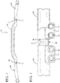
- an exemplary embodiment of an improved steering mechanism 20 for a vehicle is generally shown in Figure 1 .
- the steering mechanism 20 is advantageous because it may be quickly and simply elongated while allowing a bent configuration to be utilized for clearance around other chassis components, yet remain structurally sound in the threaded regions when this length adjuster mechanism is incorporated and clamped as described herein.
- the steering mechanism 20 may find uses in a wide range of vehicles including, for example, passenger vehicles, tractors, trucks, heavy-duty machinery, harvesters, etc.
- the exemplary steering mechanism assembly 20 includes a single center link 22 which extends in a longitudinal direction between opposite longitudinal ends 24 .
- the center link 22 is provided with a center link bore 26 which extends into the center link 22 and has female threads 28 .
- the female threads 28 are spaced from the longitudinal ends 24 of the center link 22 by unthreaded portions 30.
- the center link 22 is preferably formed as one integral piece of metal and may be shaped through any suitable process.
- the steering mechanism further includes a pair of tie rods 32 and a pair of length adjusters 34 which interconnect the tie rods 32 with the opposite longitudinal ends 24 of the center link 22 .
- the length adjusters 34 allow for precise positioning of the tie rods 32 relative to the center link 22 by allowing the center link 22 and the tie rods 32 to be controllably separated or brought closer together.
- the center link 22 is configured to push and pull on the tie rods 32 to rotate the steering knuckles (not shown) and the front wheels (not shown) of the vehicle.
- each of the tie rods 32 includes a tie rod end 36 with a tie rod bore 38 formed therein. Similar to the center link bores 26 discussed above, each tie rod bore 38 is provided with female threads 40 which are spaced from the respective tie rod end 36 by unthreaded portions 42.
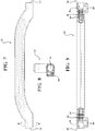
- the exemplary embodiment of the length adjuster 34 is generally symmetrical and includes a first and second threaded sections 44, 46 that are mirror images of one another and include male threads 48.
- the length adjuster 34 is also provided with an unthreaded middle section 50 which extends between said first and second threaded sections 44, 46.
- the unthreaded middle section 50 of the length adjuster 34 is provided with a tool receiving feature 52 for rotating the length adjuster 34 relative to the center link 22 and the tie rods 32.
- the tool receiving feature 52 could be, for example, generally square or hexagonally shaped for receiving an open ended wrench. However, it should be appreciated that the tool receiving region could have any suitable or configuration for receiving any suitable type of tool to rotate the length adjuster 34.
- the first threaded section 44 of the length adjuster 34 is threadedly engaged with the center link bore 26 to interconnect the length adjuster 34 with the center link 22
- the second threaded section 46 of the length adjuster 34 is threadedly engaged with the tie rod bore 38 to threadedly interconnect the length adjuster 34 with the tie rod 32.
- the unthreaded portions 30, 42 of the center link 22 and the tie rod 32 overlap with the unthreaded middle section 50 of the length adjuster 34.
- the female threads 40 of the tie rod bores 38 extend in opposite rotational directions from the female threads 28 of the center link bores 26, and the male threads 48 on the opposite first and second threaded sections 44, 46 of the length adjuster 34 extend in opposite rotational directions.
- This particular configuration enables rotation of the length adjuster 34 to selectively separate or bring together the center link 22 and tie rod 32 depending on the direction of rotation. This allows for quick and simple adjustments to the length of the steering mechanism assembly 20, thereby allowing the steering mechanism assembly 20 to be used with a range of vehicles.
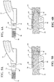
- Figures 4-6 show the length adjuster 34 in various threaded positions within one of the center link bores 26.
- a first clamping mechanism 54 is tightened to prevent unthreading of the length adjuster 34 from the center link 22. Specifically, the first clamping mechanism 54 is tightened around the overlapping unthreaded portion 30 of the center link 22 and the unthreaded middle section 50 of the length adjuster 34. Likewise, a second clamping mechanism 56 is tightened around the overlapping unthreaded portion 42 of the tie rod 32 and the unthreaded middle section 50 of the length adjuster 34 .
- the engagement of the clamping mechanisms 54 , 56 around the unthreaded areas of the center link 22, tie rod 32 , and length adjuster 34 improves the life and durability of the steering mechanism 20 by reducing the exposure of the threads to bending or buckling loads. Rather, the bending and buckling loads are transmitted between the tie rod 32 , length adjuster 34 , and center link 22 through the unthreaded areas.
- the first clamping mechanism 54 is built into the center link 22
- the second clamping mechanism 56 is built into the tie rod 32.
- Bolts 58 are employed to tighten the clamping mechanisms 54, 56 around the length adjuster 34.
- the clamping mechanisms 54, 56 each have a clam shell-tike construction.
- the first and second clamping mechanisms could alternately be formed as separate pieces from the center link and tie rod.
Landscapes
- Engineering & Computer Science (AREA)
- General Engineering & Computer Science (AREA)
- Mechanical Engineering (AREA)
- Chemical & Material Sciences (AREA)
- Combustion & Propulsion (AREA)
- Transportation (AREA)
- Steering-Linkage Mechanisms And Four-Wheel Steering (AREA)
- Mutual Connection Of Rods And Tubes (AREA)
Claims (8)
- Lenkmechanismus (20) für ein Fahrzeug, umfassend:ein zentrales Verbindungselement (22), das sich zwischen gegenüberliegenden längsgerichteten Enden (24) erstreckt, wobei jedes der längsgerichteten Enden (24) ein zentrales Verbindungselementloch (26) mit Buchsengewinden (28) aufweist, die durch gewindelose zentrale Verbindungselementabschnitte (30) von den längsgerichteten Enden (24) beabstandet sind;mindestens eine Zugstange (32) mit einem Zugstangenende (36) und einem Zugstangenloch (38) mit Buchsengewinden (40), die durch einen gewindelosen Zugstangenabschnitt (42) vom Zugstangenende (36) beabstandet sind;mindestens einen Längenversteller (34), enthaltend erste und zweite Gewindeabschnitte (44, 46) mit Steckergewinden (48) und einem gewindelosen Mittelabschnitt (50);wobei der erste Gewindeabschnitt (44) des Längenverstellers (34) das zentrale Verbindungselementloch (26) des zentralen Verbindungselements (22) gewindemäßig in Eingriff nimmt, wobei der gewindelose Abschnitt (30) des zentralen Verbindungsgelements den gewindelosen Mittelabschnitt (50) des Längenverstellers (34) überlappt, und wobei der zweite Gewindeabschnitt (46) des Längenverstellers (34) das Zugstangenloch (38) der Zugstange (32) gewindemäßig in Eingriff nimmt, wobei der gewindelose Zugstangenabschnitt (42) den gewindelosen Mittelabschnitt (50) des Längenverstellers (34) überlappt; undeine erste Klemme (54) mindestens teilweise um den überlappenden gewindelosen zentralen Verbindungsgelementabschnitt (30) und den gewindelosen Mittelabschnitt (50) des Längenverstellers (34) geklemmt ist, und eine zweite Klemme (56) mindestens teilweise um den überlappenden gewindelosen Zugstangenabschnitt (42) und den gewindelosen Mittelabschnitt (50) des Längenverstellers (34) geklemmt ist.
- Lenkmechanismus (20) nach Anspruch 1, wobei die mindestens eine Zugstange (32) ferner als ein Paar von Zugstangen (32) definiert ist und wobei der mindestens eine Längenversteller (34) ferner als ein Paar von Längenverstellern (34) definiert ist.
- Lenkmechanismus (20) nach Anspruch 1, wobei die erste Klemme (54) einstückig mit dem zentralen Verbindungsgelement (22) geformt ist.
- Lenkmechanismus (20) nach Anspruch 1, wobei die zweite Klemme (56) einstückig mit der Zugstange (32) geformt ist.
- Lenkmechanismus (20) nach Anspruch 1, wobei der gewindelose Mittelabschnitt (30) des zentralen Verbindungselements (22) ein Werkzeug in Eingriff nehmendes Merkmal (52) zum Rotieren des Längenverstellers (34) bezüglich des zentralen Verbindungsgelements (22) und der Zugstange (32) enthält, um das zentrale Verbindungselement (22) und die Zugstange (32) selektiv zu trennen oder zusammenzubringen.
- Lenkmechanismus (20) nach Anspruch 1, wobei sich die Steckergewinde (48) der ersten und zweiten Gewindeabschnitte (44, 46) des Längenverstellers (34) in entgegengesetzte Rotationsrichtungen erstrecken.
- Lenkmechanismus (20) nach Anspruch 6, wobei sich die Buchsengewinde (28) des zentralen Verbindungselementlochs (26) und die Buchsengewinde (40) des Zugstangenlochs (38) in entgegengesetzte Rotationsrichtungen erstrecken.
- Lenkmechanismus (20) nach Anspruch 1, wobei die ersten und zweiten Klemmen (54, 56) mit einer greiferförmigen Konstruktion geformt sind.
Applications Claiming Priority (2)
| Application Number | Priority Date | Filing Date | Title |
|---|---|---|---|
| US201361918200P | 2013-12-19 | 2013-12-19 | |
| PCT/US2014/071383 WO2015095647A1 (en) | 2013-12-19 | 2014-12-19 | Length adjuster and clamping mechanism for a steering mechanism |
Publications (2)
| Publication Number | Publication Date |
|---|---|
| EP3094541A1 EP3094541A1 (de) | 2016-11-23 |
| EP3094541B1 true EP3094541B1 (de) | 2019-01-16 |
Family
ID=53399205
Family Applications (1)
| Application Number | Title | Priority Date | Filing Date |
|---|---|---|---|
| EP14825056.6A Active EP3094541B1 (de) | 2013-12-19 | 2014-12-19 | Längenversteller und spannmechanismus für einen lenkmechanismus |
Country Status (8)
| Country | Link |
|---|---|
| US (1) | US9227661B2 (de) |
| EP (1) | EP3094541B1 (de) |
| JP (1) | JP2017508651A (de) |
| KR (1) | KR20160099583A (de) |
| CN (2) | CN113086005A (de) |
| CA (1) | CA2936667A1 (de) |
| MX (1) | MX370121B (de) |
| WO (1) | WO2015095647A1 (de) |
Families Citing this family (11)
| Publication number | Priority date | Publication date | Assignee | Title |
|---|---|---|---|---|
| WO2014130272A1 (en) * | 2013-02-20 | 2014-08-28 | Illinois Tool Works Inc. | Adjustable linking arm assembly |
| JP6557150B2 (ja) * | 2013-02-25 | 2019-08-07 | イリノイ トゥール ワークス インコーポレイティド | リンクアーム組立体 |
| CN108349530B (zh) * | 2015-10-23 | 2020-09-22 | 本田技研工业株式会社 | 横拉杆接头 |
| CN106043425A (zh) * | 2016-03-21 | 2016-10-26 | 东风德纳车桥有限公司 | 拉杆与接头的联接结构 |
| US10377029B2 (en) * | 2016-11-08 | 2019-08-13 | Caterpillar Inc. | Hammer sideplate tightening mechanism |
| ES2682079B1 (es) * | 2017-03-17 | 2019-06-28 | Univ Madrid Carlos Iii | Cabeza de rótula con bloqueo |
| CN107060433A (zh) * | 2017-04-21 | 2017-08-18 | 安徽鸿路钢结构(集团)股份有限公司 | 一种应用两层升降横移停车库的低高度停车方法 |
| CN107914769A (zh) * | 2017-12-25 | 2018-04-17 | 上海龙创汽车设计股份有限公司 | 一种新型碳纤维转向横拉杆机构及其制备方法 |
| US11357161B2 (en) | 2018-12-07 | 2022-06-14 | Harvest International, Inc. | Gauge wheel arm with split end and threaded bore |
| US11678603B2 (en) * | 2019-05-02 | 2023-06-20 | Bambauer Equipment | Trailered engine driven lagoon pump for Mixing and pumping manure slurries |
| JP7477970B2 (ja) * | 2019-12-26 | 2024-05-02 | カワサキモータース株式会社 | 車両 |
Family Cites Families (40)
| Publication number | Priority date | Publication date | Assignee | Title |
|---|---|---|---|---|
| US1742782A (en) | 1924-08-08 | 1930-01-07 | Gen Motors Corp | Tie-rod connection |
| US1985728A (en) * | 1927-11-15 | 1934-12-25 | Thompson Prod Inc | Ball and socket joint |
| US1910926A (en) * | 1931-05-11 | 1933-05-23 | Vergil M Lutz | Steering device for motor vehicles |
| US2533894A (en) | 1946-01-16 | 1950-12-12 | Howard I Podell | Turnbuckle or the like |
| US2723140A (en) * | 1950-02-25 | 1955-11-08 | Thompson Prod Inc | Clamp positioner |
| US3013437A (en) | 1958-10-10 | 1961-12-19 | Gen Motors Corp | Adjustable linkage |
| US3498652A (en) * | 1968-07-26 | 1970-03-03 | Trw Inc | Clamping device |
| JPS5235169B2 (de) * | 1973-02-13 | 1977-09-07 | ||
| US3938822A (en) * | 1974-10-04 | 1976-02-17 | Ford Motor Company | Adjustable tie rod assembly |
| US4614451A (en) | 1985-11-04 | 1986-09-30 | General Motors Corporation | Turnbuckle clamp assembly with orientation washer |
| DE3738432A1 (de) * | 1987-11-12 | 1989-06-01 | Trw Ehrenreich Gmbh | Verbindung eines kugelgelenkschaftes mit einem rohr |
| JPH01149871U (de) * | 1988-04-08 | 1989-10-17 | ||
| JPH0352282U (de) * | 1989-09-29 | 1991-05-21 | ||
| JPH0673500U (ja) * | 1993-03-31 | 1994-10-18 | 日野自動車工業株式会社 | ターンバックル |
| JPH07228265A (ja) * | 1994-02-18 | 1995-08-29 | Hino Motors Ltd | トーイン調整装置 |
| US5443564A (en) | 1994-04-14 | 1995-08-22 | Reaves; Donald G. | Tie rod loosening tool for use with a tie rod assembly |
| JPH09123936A (ja) * | 1995-11-02 | 1997-05-13 | Maruyama Mfg Co Ltd | 自走車両のステアリング装置 |
| US5765844A (en) | 1995-11-06 | 1998-06-16 | Trw Inc. | Linkage assembly |
| US5603583A (en) * | 1995-11-06 | 1997-02-18 | Trw Inc. | Tie rod assembly for vehicle steering linkages |
| JPH1045019A (ja) * | 1996-08-02 | 1998-02-17 | Isuzu Motors Ltd | タイロツドの取付構造 |
| JPH1199953A (ja) | 1997-09-29 | 1999-04-13 | Trw Steering Systems Japan Co Ltd | ラック・ピニオン式ステアリング装置 |
| JP2000006831A (ja) * | 1998-06-23 | 2000-01-11 | Saitama Kiki Kk | タイロッドとタイロッドエンドの取付構造 |
| JP2000159140A (ja) * | 1998-11-27 | 2000-06-13 | Showa Corp | 分割型タイロッドの連結部のロック構造 |
| JP2000199507A (ja) * | 1999-01-06 | 2000-07-18 | Showa Corp | タ―ンバックルジョイントおよびタ―ンバックルジョイントを使用したタイロッド |
| DE20116636U1 (de) | 2001-10-11 | 2002-02-14 | Landwehr Wilhelm | Axialspaltklemmutter |
| CN2685192Y (zh) * | 2004-01-15 | 2005-03-16 | 中国重型汽车集团有限公司 | 转向拉杆调整机构 |
| US7182544B2 (en) * | 2004-03-10 | 2007-02-27 | Trw Automotive U.S. Llc | Turnbuckle assembly |
| JP2006118556A (ja) * | 2004-10-20 | 2006-05-11 | Ikeya Formula Kk | ロックナット |
| CN200961299Y (zh) * | 2006-09-12 | 2007-10-17 | 薛征宇 | 用于稳固组合式框架连接结构的牵拉组件 |
| CN101591872A (zh) * | 2008-05-28 | 2009-12-02 | 张振坤 | 可调式动作连接杆 |
| DE102009001535A1 (de) * | 2009-03-13 | 2010-09-16 | Zf Friedrichshafen Ag | Baueinheit, Verfahren zur Anwendung dieser Baueinheit und Werkzeug zur Anwendung des Verfahrens |
| CN101559812B (zh) * | 2009-06-01 | 2011-02-09 | 浙江大学 | 曲柄连杆式机械转向机构 |
| US20100314510A1 (en) | 2009-06-10 | 2010-12-16 | Munn David A | Adjustable vehicle support stand |
| DE102010060251B4 (de) * | 2010-10-29 | 2017-08-24 | Ford Global Technologies, Llc. | Radaufhängung für ein Kraftfahrzeug |
| KR101270550B1 (ko) * | 2010-12-13 | 2013-06-03 | 주식회사 티앤지 | 길이 조절이 가능한 타이 로드 결합 구조 |
| US8770602B1 (en) * | 2011-05-10 | 2014-07-08 | Trw Automotive U.S. Llc | Steering linkage and method for producing same |
| CN102320327A (zh) * | 2011-07-03 | 2012-01-18 | 徐工集团工程机械股份有限公司江苏徐州工程机械研究院 | 一种大型电动轮矿用自卸车横拉杆总成 |
| CN103419843A (zh) * | 2012-05-19 | 2013-12-04 | 江苏海鹏特种车辆有限公司 | 新型转向拉杆连接装置 |
| JP6271132B2 (ja) * | 2013-02-08 | 2018-01-31 | 埼玉機器株式会社 | タイロッドとタイロッドエンド組立体 |
| CN203158071U (zh) * | 2013-04-12 | 2013-08-28 | 上海海鹏特种车辆有限公司 | X 型全转向拉杆机构 |
-
2014
- 2014-12-19 KR KR1020167016473A patent/KR20160099583A/ko not_active Application Discontinuation
- 2014-12-19 EP EP14825056.6A patent/EP3094541B1/de active Active
- 2014-12-19 US US14/576,472 patent/US9227661B2/en active Active
- 2014-12-19 WO PCT/US2014/071383 patent/WO2015095647A1/en active Application Filing
- 2014-12-19 CN CN202110565864.8A patent/CN113086005A/zh active Pending
- 2014-12-19 JP JP2016541233A patent/JP2017508651A/ja active Pending
- 2014-12-19 CN CN201480072021.2A patent/CN106458257A/zh active Pending
- 2014-12-19 MX MX2016007970A patent/MX370121B/es active IP Right Grant
- 2014-12-19 CA CA2936667A patent/CA2936667A1/en not_active Abandoned
Non-Patent Citations (1)
| Title |
|---|
| None * |
Also Published As
| Publication number | Publication date |
|---|---|
| EP3094541A1 (de) | 2016-11-23 |
| JP2017508651A (ja) | 2017-03-30 |
| MX2016007970A (es) | 2016-10-26 |
| US20150175200A1 (en) | 2015-06-25 |
| MX370121B (es) | 2019-12-02 |
| CA2936667A1 (en) | 2015-06-25 |
| US9227661B2 (en) | 2016-01-05 |
| KR20160099583A (ko) | 2016-08-22 |
| CN106458257A (zh) | 2017-02-22 |
| WO2015095647A1 (en) | 2015-06-25 |
| CN113086005A (zh) | 2021-07-09 |
Similar Documents
| Publication | Publication Date | Title |
|---|---|---|
| EP3094541B1 (de) | Längenversteller und spannmechanismus für einen lenkmechanismus | |
| US7850178B2 (en) | Motor vehicle adjustable toe link | |
| EP3093219B1 (de) | Befestigungssystem und achshilfsrahmen | |
| US7182544B2 (en) | Turnbuckle assembly | |
| US8973909B2 (en) | Cross arm bushing assembly useful for vehicle suspension | |
| DE102016008773A1 (de) | Kugelgelenk | |
| US8851490B2 (en) | Stabilizer arrangement | |
| US20190126982A1 (en) | Adjustable Tie Rod Assemblies and Methods | |
| US20200086917A1 (en) | Tie rod assembly union | |
| US4093388A (en) | Tie rod assembly for vehicles | |
| EP2772372B1 (de) | Fahrwerk für ein nutzfahrzeug und achskörper | |
| US3782221A (en) | Adjustable tie rod link | |
| KR20150054131A (ko) | 길이 조절이 가능한 타이 로드 결합 구조 | |
| WO2011028155A1 (en) | Steering link rod for a vehicle and vehicle with a steering link rod | |
| DE202014004103U1 (de) | Blockierschraube eines TPMS-Wandlers mit einem Metallventil vom Typ "Clamp-in" | |
| US8187109B2 (en) | Low load sliding intermediate shaft in a steering column for industrial vehicles | |
| WO2014161545A1 (de) | Flanschanordnung, fahrwerksaktuator und verfahren zur herstellung der flanschanordnung | |
| JP6928308B2 (ja) | リンクロッドとリンクロッドエンド組立体 | |
| EP3573851A1 (de) | Gelenkgabel und aktuator mit gelenkgabel | |
| DE102015218150B4 (de) | Verbindungsstruktur für Fahrzeugrahmenelemente | |
| US20150291211A1 (en) | Device for protecting against overloading | |
| EP3456586B1 (de) | Vorrichtung und verfahren zur positionsgenauen, wenigstens teilweisen befestigung von fahrzeugleuchten an fahrzeugen, insbesondere kraftfahrzeugen, sowie fahrzeugleuchte | |
| CN111788110A (zh) | 用于机动车辆的横向管总成 | |
| JP2021075072A (ja) | リンクロッドとリンクロッドエンド組立体 | |
| US20060174469A1 (en) | Method for producing a cam for a clutch, device for milling the contour surfaces of the cam, and device for shortening the cam journal |
Legal Events
| Date | Code | Title | Description |
|---|---|---|---|
| PUAI | Public reference made under article 153(3) epc to a published international application that has entered the european phase |
Free format text: ORIGINAL CODE: 0009012 |
|
| 17P | Request for examination filed |
Effective date: 20160713 |
|
| AK | Designated contracting states |
Kind code of ref document: A1 Designated state(s): AL AT BE BG CH CY CZ DE DK EE ES FI FR GB GR HR HU IE IS IT LI LT LU LV MC MK MT NL NO PL PT RO RS SE SI SK SM TR |
|
| AX | Request for extension of the european patent |
Extension state: BA ME |
|
| DAX | Request for extension of the european patent (deleted) | ||
| STAA | Information on the status of an ep patent application or granted ep patent |
Free format text: STATUS: EXAMINATION IS IN PROGRESS |
|
| 17Q | First examination report despatched |
Effective date: 20180223 |
|
| RAP1 | Party data changed (applicant data changed or rights of an application transferred) |
Owner name: FEDERAL-MOGUL MOTORPARTS CORPORATION |
|
| RAP1 | Party data changed (applicant data changed or rights of an application transferred) |
Owner name: FEDERAL-MOGUL MOTORPARTS LLC |
|
| GRAP | Despatch of communication of intention to grant a patent |
Free format text: ORIGINAL CODE: EPIDOSNIGR1 |
|
| STAA | Information on the status of an ep patent application or granted ep patent |
Free format text: STATUS: GRANT OF PATENT IS INTENDED |
|
| RIC1 | Information provided on ipc code assigned before grant |
Ipc: F16B 39/02 20060101ALI20181008BHEP Ipc: B62D 7/20 20060101AFI20181008BHEP Ipc: F16C 7/06 20060101ALI20181008BHEP Ipc: B62D 7/16 20060101ALI20181008BHEP Ipc: F16B 7/06 20060101ALI20181008BHEP |
|
| GRAS | Grant fee paid |
Free format text: ORIGINAL CODE: EPIDOSNIGR3 |
|
| INTG | Intention to grant announced |
Effective date: 20181029 |
|
| GRAA | (expected) grant |
Free format text: ORIGINAL CODE: 0009210 |
|
| STAA | Information on the status of an ep patent application or granted ep patent |
Free format text: STATUS: THE PATENT HAS BEEN GRANTED |
|
| AK | Designated contracting states |
Kind code of ref document: B1 Designated state(s): AL AT BE BG CH CY CZ DE DK EE ES FI FR GB GR HR HU IE IS IT LI LT LU LV MC MK MT NL NO PL PT RO RS SE SI SK SM TR |
|
| REG | Reference to a national code |
Ref country code: GB Ref legal event code: FG4D |
|
| REG | Reference to a national code |
Ref country code: CH Ref legal event code: EP |
|
| REG | Reference to a national code |
Ref country code: IE Ref legal event code: FG4D |
|
| REG | Reference to a national code |
Ref country code: DE Ref legal event code: R096 Ref document number: 602014040109 Country of ref document: DE |
|
| REG | Reference to a national code |
Ref country code: AT Ref legal event code: REF Ref document number: 1089499 Country of ref document: AT Kind code of ref document: T Effective date: 20190215 |
|
| REG | Reference to a national code |
Ref country code: NL Ref legal event code: MP Effective date: 20190116 |
|
| REG | Reference to a national code |
Ref country code: LT Ref legal event code: MG4D |
|
| PG25 | Lapsed in a contracting state [announced via postgrant information from national office to epo] |
Ref country code: NL Free format text: LAPSE BECAUSE OF FAILURE TO SUBMIT A TRANSLATION OF THE DESCRIPTION OR TO PAY THE FEE WITHIN THE PRESCRIBED TIME-LIMIT Effective date: 20190116 |
|
| REG | Reference to a national code |
Ref country code: AT Ref legal event code: MK05 Ref document number: 1089499 Country of ref document: AT Kind code of ref document: T Effective date: 20190116 |
|
| PG25 | Lapsed in a contracting state [announced via postgrant information from national office to epo] |
Ref country code: NO Free format text: LAPSE BECAUSE OF FAILURE TO SUBMIT A TRANSLATION OF THE DESCRIPTION OR TO PAY THE FEE WITHIN THE PRESCRIBED TIME-LIMIT Effective date: 20190416 Ref country code: FI Free format text: LAPSE BECAUSE OF FAILURE TO SUBMIT A TRANSLATION OF THE DESCRIPTION OR TO PAY THE FEE WITHIN THE PRESCRIBED TIME-LIMIT Effective date: 20190116 Ref country code: PL Free format text: LAPSE BECAUSE OF FAILURE TO SUBMIT A TRANSLATION OF THE DESCRIPTION OR TO PAY THE FEE WITHIN THE PRESCRIBED TIME-LIMIT Effective date: 20190116 Ref country code: LT Free format text: LAPSE BECAUSE OF FAILURE TO SUBMIT A TRANSLATION OF THE DESCRIPTION OR TO PAY THE FEE WITHIN THE PRESCRIBED TIME-LIMIT Effective date: 20190116 Ref country code: ES Free format text: LAPSE BECAUSE OF FAILURE TO SUBMIT A TRANSLATION OF THE DESCRIPTION OR TO PAY THE FEE WITHIN THE PRESCRIBED TIME-LIMIT Effective date: 20190116 Ref country code: SE Free format text: LAPSE BECAUSE OF FAILURE TO SUBMIT A TRANSLATION OF THE DESCRIPTION OR TO PAY THE FEE WITHIN THE PRESCRIBED TIME-LIMIT Effective date: 20190116 Ref country code: PT Free format text: LAPSE BECAUSE OF FAILURE TO SUBMIT A TRANSLATION OF THE DESCRIPTION OR TO PAY THE FEE WITHIN THE PRESCRIBED TIME-LIMIT Effective date: 20190516 |
|
| PG25 | Lapsed in a contracting state [announced via postgrant information from national office to epo] |
Ref country code: HR Free format text: LAPSE BECAUSE OF FAILURE TO SUBMIT A TRANSLATION OF THE DESCRIPTION OR TO PAY THE FEE WITHIN THE PRESCRIBED TIME-LIMIT Effective date: 20190116 Ref country code: RS Free format text: LAPSE BECAUSE OF FAILURE TO SUBMIT A TRANSLATION OF THE DESCRIPTION OR TO PAY THE FEE WITHIN THE PRESCRIBED TIME-LIMIT Effective date: 20190116 Ref country code: LV Free format text: LAPSE BECAUSE OF FAILURE TO SUBMIT A TRANSLATION OF THE DESCRIPTION OR TO PAY THE FEE WITHIN THE PRESCRIBED TIME-LIMIT Effective date: 20190116 Ref country code: IS Free format text: LAPSE BECAUSE OF FAILURE TO SUBMIT A TRANSLATION OF THE DESCRIPTION OR TO PAY THE FEE WITHIN THE PRESCRIBED TIME-LIMIT Effective date: 20190516 Ref country code: GR Free format text: LAPSE BECAUSE OF FAILURE TO SUBMIT A TRANSLATION OF THE DESCRIPTION OR TO PAY THE FEE WITHIN THE PRESCRIBED TIME-LIMIT Effective date: 20190417 Ref country code: BG Free format text: LAPSE BECAUSE OF FAILURE TO SUBMIT A TRANSLATION OF THE DESCRIPTION OR TO PAY THE FEE WITHIN THE PRESCRIBED TIME-LIMIT Effective date: 20190416 |
|
| REG | Reference to a national code |
Ref country code: DE Ref legal event code: R097 Ref document number: 602014040109 Country of ref document: DE |
|
| PG25 | Lapsed in a contracting state [announced via postgrant information from national office to epo] |
Ref country code: AT Free format text: LAPSE BECAUSE OF FAILURE TO SUBMIT A TRANSLATION OF THE DESCRIPTION OR TO PAY THE FEE WITHIN THE PRESCRIBED TIME-LIMIT Effective date: 20190116 Ref country code: AL Free format text: LAPSE BECAUSE OF FAILURE TO SUBMIT A TRANSLATION OF THE DESCRIPTION OR TO PAY THE FEE WITHIN THE PRESCRIBED TIME-LIMIT Effective date: 20190116 Ref country code: SK Free format text: LAPSE BECAUSE OF FAILURE TO SUBMIT A TRANSLATION OF THE DESCRIPTION OR TO PAY THE FEE WITHIN THE PRESCRIBED TIME-LIMIT Effective date: 20190116 Ref country code: CZ Free format text: LAPSE BECAUSE OF FAILURE TO SUBMIT A TRANSLATION OF THE DESCRIPTION OR TO PAY THE FEE WITHIN THE PRESCRIBED TIME-LIMIT Effective date: 20190116 Ref country code: RO Free format text: LAPSE BECAUSE OF FAILURE TO SUBMIT A TRANSLATION OF THE DESCRIPTION OR TO PAY THE FEE WITHIN THE PRESCRIBED TIME-LIMIT Effective date: 20190116 Ref country code: EE Free format text: LAPSE BECAUSE OF FAILURE TO SUBMIT A TRANSLATION OF THE DESCRIPTION OR TO PAY THE FEE WITHIN THE PRESCRIBED TIME-LIMIT Effective date: 20190116 Ref country code: DK Free format text: LAPSE BECAUSE OF FAILURE TO SUBMIT A TRANSLATION OF THE DESCRIPTION OR TO PAY THE FEE WITHIN THE PRESCRIBED TIME-LIMIT Effective date: 20190116 |
|
| PLBE | No opposition filed within time limit |
Free format text: ORIGINAL CODE: 0009261 |
|
| STAA | Information on the status of an ep patent application or granted ep patent |
Free format text: STATUS: NO OPPOSITION FILED WITHIN TIME LIMIT |
|
| PG25 | Lapsed in a contracting state [announced via postgrant information from national office to epo] |
Ref country code: SM Free format text: LAPSE BECAUSE OF FAILURE TO SUBMIT A TRANSLATION OF THE DESCRIPTION OR TO PAY THE FEE WITHIN THE PRESCRIBED TIME-LIMIT Effective date: 20190116 |
|
| 26N | No opposition filed |
Effective date: 20191017 |
|
| PG25 | Lapsed in a contracting state [announced via postgrant information from national office to epo] |
Ref country code: SI Free format text: LAPSE BECAUSE OF FAILURE TO SUBMIT A TRANSLATION OF THE DESCRIPTION OR TO PAY THE FEE WITHIN THE PRESCRIBED TIME-LIMIT Effective date: 20190116 |
|
| PGFP | Annual fee paid to national office [announced via postgrant information from national office to epo] |
Ref country code: FR Payment date: 20191122 Year of fee payment: 6 |
|
| PG25 | Lapsed in a contracting state [announced via postgrant information from national office to epo] |
Ref country code: TR Free format text: LAPSE BECAUSE OF FAILURE TO SUBMIT A TRANSLATION OF THE DESCRIPTION OR TO PAY THE FEE WITHIN THE PRESCRIBED TIME-LIMIT Effective date: 20190116 |
|
| PGFP | Annual fee paid to national office [announced via postgrant information from national office to epo] |
Ref country code: IT Payment date: 20191220 Year of fee payment: 6 |
|
| REG | Reference to a national code |
Ref country code: CH Ref legal event code: PL |
|
| REG | Reference to a national code |
Ref country code: BE Ref legal event code: MM Effective date: 20191231 |
|
| PG25 | Lapsed in a contracting state [announced via postgrant information from national office to epo] |
Ref country code: MC Free format text: LAPSE BECAUSE OF FAILURE TO SUBMIT A TRANSLATION OF THE DESCRIPTION OR TO PAY THE FEE WITHIN THE PRESCRIBED TIME-LIMIT Effective date: 20190116 |
|
| GBPC | Gb: european patent ceased through non-payment of renewal fee |
Effective date: 20191219 |
|
| PG25 | Lapsed in a contracting state [announced via postgrant information from national office to epo] |
Ref country code: IE Free format text: LAPSE BECAUSE OF NON-PAYMENT OF DUE FEES Effective date: 20191219 Ref country code: LU Free format text: LAPSE BECAUSE OF NON-PAYMENT OF DUE FEES Effective date: 20191219 Ref country code: GB Free format text: LAPSE BECAUSE OF NON-PAYMENT OF DUE FEES Effective date: 20191219 |
|
| PG25 | Lapsed in a contracting state [announced via postgrant information from national office to epo] |
Ref country code: CH Free format text: LAPSE BECAUSE OF NON-PAYMENT OF DUE FEES Effective date: 20191231 Ref country code: BE Free format text: LAPSE BECAUSE OF NON-PAYMENT OF DUE FEES Effective date: 20191231 Ref country code: LI Free format text: LAPSE BECAUSE OF NON-PAYMENT OF DUE FEES Effective date: 20191231 |
|
| PG25 | Lapsed in a contracting state [announced via postgrant information from national office to epo] |
Ref country code: CY Free format text: LAPSE BECAUSE OF FAILURE TO SUBMIT A TRANSLATION OF THE DESCRIPTION OR TO PAY THE FEE WITHIN THE PRESCRIBED TIME-LIMIT Effective date: 20190116 |
|
| PG25 | Lapsed in a contracting state [announced via postgrant information from national office to epo] |
Ref country code: HU Free format text: LAPSE BECAUSE OF FAILURE TO SUBMIT A TRANSLATION OF THE DESCRIPTION OR TO PAY THE FEE WITHIN THE PRESCRIBED TIME-LIMIT; INVALID AB INITIO Effective date: 20141219 Ref country code: MT Free format text: LAPSE BECAUSE OF FAILURE TO SUBMIT A TRANSLATION OF THE DESCRIPTION OR TO PAY THE FEE WITHIN THE PRESCRIBED TIME-LIMIT Effective date: 20190116 |
|
| PG25 | Lapsed in a contracting state [announced via postgrant information from national office to epo] |
Ref country code: IT Free format text: LAPSE BECAUSE OF NON-PAYMENT OF DUE FEES Effective date: 20201219 Ref country code: FR Free format text: LAPSE BECAUSE OF NON-PAYMENT OF DUE FEES Effective date: 20201231 |
|
| PG25 | Lapsed in a contracting state [announced via postgrant information from national office to epo] |
Ref country code: MK Free format text: LAPSE BECAUSE OF FAILURE TO SUBMIT A TRANSLATION OF THE DESCRIPTION OR TO PAY THE FEE WITHIN THE PRESCRIBED TIME-LIMIT Effective date: 20190116 |
|
| PGFP | Annual fee paid to national office [announced via postgrant information from national office to epo] |
Ref country code: DE Payment date: 20231121 Year of fee payment: 10 |