EP3092469B1 - Optical pyrometer - Google Patents
Optical pyrometer Download PDFInfo
- Publication number
- EP3092469B1 EP3092469B1 EP15700955.6A EP15700955A EP3092469B1 EP 3092469 B1 EP3092469 B1 EP 3092469B1 EP 15700955 A EP15700955 A EP 15700955A EP 3092469 B1 EP3092469 B1 EP 3092469B1
- Authority
- EP
- European Patent Office
- Prior art keywords
- sleeve
- bayonet rod
- grooves
- pins
- rod
- Prior art date
- Legal status (The legal status is an assumption and is not a legal conclusion. Google has not performed a legal analysis and makes no representation as to the accuracy of the status listed.)
- Active
Links
- 230000003287 optical effect Effects 0.000 title claims description 24
- 239000011819 refractory material Substances 0.000 claims description 26
- 229910052751 metal Inorganic materials 0.000 claims description 24
- 239000002184 metal Substances 0.000 claims description 23
- 230000000903 blocking effect Effects 0.000 claims description 15
- 230000001681 protective effect Effects 0.000 claims description 15
- 238000000034 method Methods 0.000 claims description 9
- 239000007789 gas Substances 0.000 description 14
- 238000005259 measurement Methods 0.000 description 5
- XKRFYHLGVUSROY-UHFFFAOYSA-N Argon Chemical compound [Ar] XKRFYHLGVUSROY-UHFFFAOYSA-N 0.000 description 4
- 239000000428 dust Substances 0.000 description 4
- 238000009529 body temperature measurement Methods 0.000 description 3
- 238000004519 manufacturing process Methods 0.000 description 3
- 229910052786 argon Inorganic materials 0.000 description 2
- 230000001419 dependent effect Effects 0.000 description 2
- 239000003517 fume Substances 0.000 description 2
- 238000010438 heat treatment Methods 0.000 description 2
- 239000000203 mixture Substances 0.000 description 2
- 239000000243 solution Substances 0.000 description 2
- 206010063493 Premature ageing Diseases 0.000 description 1
- 239000000956 alloy Substances 0.000 description 1
- 229910045601 alloy Inorganic materials 0.000 description 1
- 230000006835 compression Effects 0.000 description 1
- 238000007906 compression Methods 0.000 description 1
- 230000005494 condensation Effects 0.000 description 1
- 238000009833 condensation Methods 0.000 description 1
- 238000009749 continuous casting Methods 0.000 description 1
- 230000003247 decreasing effect Effects 0.000 description 1
- 230000008021 deposition Effects 0.000 description 1
- 230000000694 effects Effects 0.000 description 1
- 229910002804 graphite Inorganic materials 0.000 description 1
- 239000010439 graphite Substances 0.000 description 1
- 229910001026 inconel Inorganic materials 0.000 description 1
- 238000002347 injection Methods 0.000 description 1
- 239000007924 injection Substances 0.000 description 1
- 238000009434 installation Methods 0.000 description 1
- 238000005304 joining Methods 0.000 description 1
- 238000003754 machining Methods 0.000 description 1
- 229910000510 noble metal Inorganic materials 0.000 description 1
- 239000013307 optical fiber Substances 0.000 description 1
- 238000010408 sweeping Methods 0.000 description 1
Images


Classifications
-
- B—PERFORMING OPERATIONS; TRANSPORTING
- B22—CASTING; POWDER METALLURGY
- B22D—CASTING OF METALS; CASTING OF OTHER SUBSTANCES BY THE SAME PROCESSES OR DEVICES
- B22D2/00—Arrangement of indicating or measuring devices, e.g. for temperature or viscosity of the fused mass
- B22D2/006—Arrangement of indicating or measuring devices, e.g. for temperature or viscosity of the fused mass for the temperature of the molten metal
-
- B—PERFORMING OPERATIONS; TRANSPORTING
- B22—CASTING; POWDER METALLURGY
- B22D—CASTING OF METALS; CASTING OF OTHER SUBSTANCES BY THE SAME PROCESSES OR DEVICES
- B22D41/00—Casting melt-holding vessels, e.g. ladles, tundishes, cups or the like
- B22D41/14—Closures
- B22D41/16—Closures stopper-rod type, i.e. a stopper-rod being positioned downwardly through the vessel and the metal therein, for selective registry with the pouring opening
- B22D41/18—Stopper-rods therefor
-
- F—MECHANICAL ENGINEERING; LIGHTING; HEATING; WEAPONS; BLASTING
- F16—ENGINEERING ELEMENTS AND UNITS; GENERAL MEASURES FOR PRODUCING AND MAINTAINING EFFECTIVE FUNCTIONING OF MACHINES OR INSTALLATIONS; THERMAL INSULATION IN GENERAL
- F16B—DEVICES FOR FASTENING OR SECURING CONSTRUCTIONAL ELEMENTS OR MACHINE PARTS TOGETHER, e.g. NAILS, BOLTS, CIRCLIPS, CLAMPS, CLIPS OR WEDGES; JOINTS OR JOINTING
- F16B7/00—Connections of rods or tubes, e.g. of non-circular section, mutually, including resilient connections
- F16B7/20—Connections of rods or tubes, e.g. of non-circular section, mutually, including resilient connections using bayonet connections
-
- F—MECHANICAL ENGINEERING; LIGHTING; HEATING; WEAPONS; BLASTING
- F27—FURNACES; KILNS; OVENS; RETORTS
- F27D—DETAILS OR ACCESSORIES OF FURNACES, KILNS, OVENS, OR RETORTS, IN SO FAR AS THEY ARE OF KINDS OCCURRING IN MORE THAN ONE KIND OF FURNACE
- F27D21/00—Arrangements of monitoring devices; Arrangements of safety devices
- F27D21/0014—Devices for monitoring temperature
-
- G—PHYSICS
- G01—MEASURING; TESTING
- G01J—MEASUREMENT OF INTENSITY, VELOCITY, SPECTRAL CONTENT, POLARISATION, PHASE OR PULSE CHARACTERISTICS OF INFRARED, VISIBLE OR ULTRAVIOLET LIGHT; COLORIMETRY; RADIATION PYROMETRY
- G01J5/00—Radiation pyrometry, e.g. infrared or optical thermometry
- G01J5/0037—Radiation pyrometry, e.g. infrared or optical thermometry for sensing the heat emitted by liquids
- G01J5/004—Radiation pyrometry, e.g. infrared or optical thermometry for sensing the heat emitted by liquids by molten metals
-
- G—PHYSICS
- G01—MEASURING; TESTING
- G01J—MEASUREMENT OF INTENSITY, VELOCITY, SPECTRAL CONTENT, POLARISATION, PHASE OR PULSE CHARACTERISTICS OF INFRARED, VISIBLE OR ULTRAVIOLET LIGHT; COLORIMETRY; RADIATION PYROMETRY
- G01J5/00—Radiation pyrometry, e.g. infrared or optical thermometry
- G01J5/02—Constructional details
- G01J5/04—Casings
- G01J5/041—Mountings in enclosures or in a particular environment
- G01J5/042—High-temperature environment
-
- G—PHYSICS
- G01—MEASURING; TESTING
- G01J—MEASUREMENT OF INTENSITY, VELOCITY, SPECTRAL CONTENT, POLARISATION, PHASE OR PULSE CHARACTERISTICS OF INFRARED, VISIBLE OR ULTRAVIOLET LIGHT; COLORIMETRY; RADIATION PYROMETRY
- G01J5/00—Radiation pyrometry, e.g. infrared or optical thermometry
- G01J5/02—Constructional details
- G01J5/05—Means for preventing contamination of the components of the optical system; Means for preventing obstruction of the radiation path
-
- G—PHYSICS
- G01—MEASURING; TESTING
- G01J—MEASUREMENT OF INTENSITY, VELOCITY, SPECTRAL CONTENT, POLARISATION, PHASE OR PULSE CHARACTERISTICS OF INFRARED, VISIBLE OR ULTRAVIOLET LIGHT; COLORIMETRY; RADIATION PYROMETRY
- G01J5/00—Radiation pyrometry, e.g. infrared or optical thermometry
- G01J5/02—Constructional details
- G01J5/08—Optical arrangements
- G01J5/0887—Integrating cavities mimicking black bodies, wherein the heat propagation between the black body and the measuring element does not occur within a solid; Use of bodies placed inside the fluid stream for measurement of the temperature of gases; Use of the reemission from a surface, e.g. reflective surface; Emissivity enhancement by multiple reflections
-
- G—PHYSICS
- G01—MEASURING; TESTING
- G01J—MEASUREMENT OF INTENSITY, VELOCITY, SPECTRAL CONTENT, POLARISATION, PHASE OR PULSE CHARACTERISTICS OF INFRARED, VISIBLE OR ULTRAVIOLET LIGHT; COLORIMETRY; RADIATION PYROMETRY
- G01J5/00—Radiation pyrometry, e.g. infrared or optical thermometry
- G01J5/02—Constructional details
- G01J5/08—Optical arrangements
- G01J5/0893—Arrangements to attach devices to a pyrometer, i.e. attaching an optical interface; Spatial relative arrangement of optical elements, e.g. folded beam path
Definitions
- the present invention is in the field of continuous temperature measurement.
- the present invention relates to the continuous temperature measurement of molten metal during the continuous casting thereof. Specifically, it is critical to control this temperature in order to ensure optimum quality of the cast metal.
- thermocouples that use type B thermocouples or thermocouples made of an alloy of noble metals
- infrared optical sensors The drawback with the former is their premature ageing due to the extreme use conditions. Frequent replacement of the sensors has to be carried out, and this represents a non-negligible cost.
- Infrared optical sensors also known as optical pyrometers, have, in contrast to thermocouples, a much longer service life while providing temperature measurements that are precise and stable over time as long as the measuring zone remains centred in the interior of the sleeve.
- the International Application WO-A2-03/029771 discloses an assembly of an optical pyrometer and a sleeve made of refractory material which is dipped into a bath of molten metal in order to measure the temperature thereof.
- the pyrometer and the protective sleeve are secured so as to keep the measuring zone centred in the interior of the sleeve in spite of the impacts and vibrations to which the assembly can be subjected.
- a significant problem encountered in the use of such a device is the emission of gaseous components by the refractory material which, by condensing on the optical lens, can disturb the measurement.
- Patent EP-B1-1893959 likewise discloses a measuring device that uses an optical pyrometer comprising a sleeve made of refractory material that is dipped into the molten metal.
- This sleeve is centred by way of a guide tube and is supported on a fixed seat by way of articulated locking rods that are provided with wing nuts.
- the device then has to be placed in a cooled enclosure.
- the disadvantages of this device are numerous: specifically it requires that the sleeve made of refractory material is supported during the tightening of the nuts.
- the sleeve is centred by the guide tube of the measuring head which slides through the internal cavity of the sleeve and also by the positioning of the sleeve on the seat.
- the positioning thus depends on the external dimensions of the sleeve and the tolerances during its manufacture. Thus, when it is replaced, the measuring zone may move, with the consequence of less precise measurement.
- the object of the present invention is to remedy these drawbacks (difficulty of assembly, disassembling, keeping the measuring zone centred, disturbance of the measurement by the emission of gaseous components from the sleeve made of refractory material).
- the subject of the invention is a device for measuring the temperature of a bath of molten metal as defined in claim 1, thus comprising:
- first fixing and immediate centring is effected by a relative rotational movement of the sleeve with respect to the optical head.
- a single operator is enough.
- the peg (21) of the locking component (6) is carried along by the rotation.
- the rotation of the locking component (6) carries along the means for tensioning the spring - such as a lever (9) secured thereto - visually indicating to the operator that fixing has been effected.
- the operator partially releases the tension in the spring (11) by way of the lever (9). Flexibility in the fixing is thus produced by the control of the clamping force which changes during heating.
- Another non-negligible advantage of the device is that it can be disassembled rapidly at high temperature without the sleeve having to be handled. After a measuring period of 15 to 24 hours, it is conventional to replace the sleeve during the replacement of the tundish. An effective way of proceeding is to disassemble the device above the tundish and to let the sleeve fall into the tundish needing to be replaced. The invention makes this step easy, quick and without danger for the operator. Specifically, all he has to do is lower the lever and then rotate the lever in order to disconnect the sleeve without having to touch it.
- the invention also includes one or more features from the following list:
- the grooves (15) designed to guide the pins also serve as passageways for the evacuation of gaseous components emitted by the sleeve made of refractory material when it is brought to high temperature.
- the quantity of gas and dust which reach the protective window (12) is thus reduced.
- the measuring window may also be swept by the injection of a gas, preferably argon, which prevents any disturbance of the measurement by the deposition of condensation on the protective window.
- a vent tube provides an additional improvement to the process.
- Figure 6 shows a device with a vent tube (25).
- a sleeve made at least partially of refractory material as defined in claim 5 a method for assembling together a sleeve and an optical head according to claim 9 and a method for disassembling a sleeve and an optical head according to claim 10.
- the advantages are greater ease of use and increased safety, as explained above.
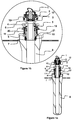
- Figures 1a, 1b show a measuring device according to one particular embodiment of the invention, Figure 1b being an enlargement of the upper region of Figure 1a .
- Said figures show a device comprising:
- the tensioning means and the means for rotating about the bayonet rod (4) are one and the same: the double cam lever (9) is used to turn the locking cone (6).
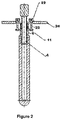
- Figure 2 shows another embodiment: a nut(22)/bolt (23) system which is used for tensioning and is connected to two handles (24) for turning the locking cone (6).
- the grooves (15) are also used for evacuating gases emitted by the refractory material.
- the evacuation of the gases can be improved by creating a negative pressure in the sleeve (8) by way of a Venturi system for example. The gases will then be sucked out towards the outlet.
- Figure 5 shows the sequence of mounting and removing the sleeve (8) (a to f): the operator inserts the sleeve (8) by bringing the pegs (21) of the locking cone (6) into correspondence with the notches (14) in the upper part of the sleeve (8), position (a). Then, the pins (7) of the bayonet rod (4), which are offset through a quarter turn with respect to the pegs (21) of the locking cone, pass into the grooves (15) in the metal insert.
- the measuring device is ready to be used. It then suffices to move the assembly above a tundish.
- Position (d) shows the device in operation, and the bottom of the sleeve (8) is hot.
- a further subject of the invention is a method for measuring the temperature of a bath of molten metal, comprising the following steps of:
- the method for assembling the sleeve on the optical head can be applied to the assembling of a stopper rod on a fixing rod.
- the stopper rod thus has the features defined in claim 12:
- Such a stopper rod can be used with a system for fixing the device described above, wherein the elements intended to measure the temperature can optionally have been omitted.
- Figure 6 shows a device according to claim 4.
- the vent tube is interlocked with the bayonet rod (4) and held with the aid of a screw.
- the cavity of the vent tube is flared in its lower part so as to avoid the situation in which a slight misalignment of the vent tube prevents the range of the pyrometer from reaching the bottom of the sleeve.
Landscapes
- Engineering & Computer Science (AREA)
- Physics & Mathematics (AREA)
- General Physics & Mathematics (AREA)
- Spectroscopy & Molecular Physics (AREA)
- Mechanical Engineering (AREA)
- General Engineering & Computer Science (AREA)
- Radiation Pyrometers (AREA)
- Waste-Gas Treatment And Other Accessory Devices For Furnaces (AREA)
Priority Applications (4)
| Application Number | Priority Date | Filing Date | Title |
|---|---|---|---|
| EP15700955.6A EP3092469B1 (en) | 2014-01-08 | 2015-01-05 | Optical pyrometer |
| SI201530887T SI3092469T1 (sl) | 2014-01-08 | 2015-01-05 | Optični pirometer |
| RSP20191391 RS59452B1 (sr) | 2014-01-08 | 2015-01-05 | Optički pirometar |
| PL15700955T PL3092469T3 (pl) | 2014-01-08 | 2015-01-05 | Pirometr optyczny |
Applications Claiming Priority (3)
| Application Number | Priority Date | Filing Date | Title |
|---|---|---|---|
| EP14150465 | 2014-01-08 | ||
| EP15700955.6A EP3092469B1 (en) | 2014-01-08 | 2015-01-05 | Optical pyrometer |
| PCT/EP2015/050057 WO2015104241A1 (en) | 2014-01-08 | 2015-01-05 | Optical pyrometer |
Publications (2)
| Publication Number | Publication Date |
|---|---|
| EP3092469A1 EP3092469A1 (en) | 2016-11-16 |
| EP3092469B1 true EP3092469B1 (en) | 2019-07-31 |
Family
ID=49886854
Family Applications (1)
| Application Number | Title | Priority Date | Filing Date |
|---|---|---|---|
| EP15700955.6A Active EP3092469B1 (en) | 2014-01-08 | 2015-01-05 | Optical pyrometer |
Country Status (22)
| Country | Link |
|---|---|
| US (1) | US10126174B2 (ko) |
| EP (1) | EP3092469B1 (ko) |
| JP (1) | JP6510538B2 (ko) |
| KR (1) | KR102267525B1 (ko) |
| CN (1) | CN107076615B (ko) |
| AR (1) | AR099033A1 (ko) |
| AU (1) | AU2015205700B2 (ko) |
| BR (1) | BR112016014866B1 (ko) |
| CA (1) | CA2934583C (ko) |
| ES (1) | ES2750973T3 (ko) |
| HU (1) | HUE047158T2 (ko) |
| MX (1) | MX2016009053A (ko) |
| MY (1) | MY193247A (ko) |
| PL (1) | PL3092469T3 (ko) |
| PT (1) | PT3092469T (ko) |
| RS (1) | RS59452B1 (ko) |
| RU (1) | RU2667319C2 (ko) |
| SI (1) | SI3092469T1 (ko) |
| TW (1) | TWI657234B (ko) |
| UA (1) | UA117388C2 (ko) |
| WO (1) | WO2015104241A1 (ko) |
| ZA (1) | ZA201604493B (ko) |
Families Citing this family (5)
| Publication number | Priority date | Publication date | Assignee | Title |
|---|---|---|---|---|
| UA117388C2 (uk) * | 2014-01-08 | 2018-07-25 | Везувіус Груп, С.А. | Оптичний пірометр |
| WO2018108789A1 (en) | 2016-12-12 | 2018-06-21 | Vesuvius Group, S.A. | Stopper equipped with an integrated slag detection device |
| CN107931547A (zh) * | 2017-12-25 | 2018-04-20 | 南京佛利蒙特测控技术有限公司 | 一种用于检测炼钢连铸过程中钢水温度的红外测温系统 |
| PL3685781T3 (pl) | 2019-01-24 | 2022-07-11 | Erbe Elektromedizin Gmbh | Przyrząd do koagulacji tkanek |
| CN114776680B (zh) * | 2022-04-14 | 2023-12-08 | 常熟理工学院 | 一种新型快拆的圆管连接件结构 |
Family Cites Families (30)
| Publication number | Priority date | Publication date | Assignee | Title |
|---|---|---|---|---|
| GB190928010A (en) * | 1909-12-01 | 1910-10-06 | Arthur Robert Thomas Woods | Improvements in or relating to Thermometers for Taking the Internal Temperature of Meat, Carcases, or the like. |
| US2232594A (en) * | 1938-06-23 | 1941-02-18 | Leeds & Northrup Co | Radiation pyrometer |
| US3935032A (en) * | 1973-11-15 | 1976-01-27 | Libbey-Owens-Ford Company | Sheathed thermocouple |
| US4038105A (en) * | 1975-10-08 | 1977-07-26 | Libbey-Owens-Ford Company | Radiation shields for aspirating pyrometers |
| JPH0528497Y2 (ko) * | 1987-12-03 | 1993-07-22 | ||
| JPH0238932A (ja) * | 1988-07-29 | 1990-02-08 | Sumitomo Metal Ind Ltd | 溶融金属の連続測温方法 |
| DE3912751C1 (ko) | 1989-04-19 | 1990-09-27 | Vetco Sanitec Gmbh, 3100 Celle, De | |
| SU1733970A1 (ru) * | 1990-03-02 | 1992-05-15 | Институт проблем литья АН УССР | Устройство дл измерени температуры расплава в печи |
| JPH075043A (ja) * | 1992-12-07 | 1995-01-10 | Seiichi Okuhara | 光学的温度測定装置の受光部 |
| FR2703455B1 (fr) * | 1993-04-01 | 1995-05-12 | Europ Gas Turbines Sa | Pyromètre bichromatique. |
| US5421652A (en) * | 1993-12-21 | 1995-06-06 | General Electric Company | Pyrometer adapter |
| US6733173B1 (en) * | 1996-12-19 | 2004-05-11 | Diamond Power International, Inc. | Pyrometer for measuring the temperature of a gas component within a furnace |
| DE19707373C1 (de) | 1997-02-25 | 1998-02-05 | Storz Karl Gmbh & Co | Bajonettkupplung zum lösbaren Verbinden zweier Rohrschaftinstrumente oder -instrumententeile |
| US6698920B1 (en) * | 2000-05-08 | 2004-03-02 | General Electric Company | Temperature measuring system and optical switch used therein |
| JP2002107231A (ja) * | 2000-09-27 | 2002-04-10 | Risho:Kk | 溶融金属内部温度測定用放射温度計 |
| JP2002323377A (ja) | 2001-04-25 | 2002-11-08 | Nippon Crucible Co Ltd | 炉内温度測定装置 |
| EP1298423A1 (en) | 2001-10-01 | 2003-04-02 | Vesuvius Crucible Company | Pyrometer |
| ITMI20012278A1 (it) * | 2001-10-30 | 2003-04-30 | Techint Spa | Dispositivo e metodo per misurazione discreta e continua della temperatura di metallo liquido in un forno o recipiente per la sua produzione |
| WO2005059185A1 (en) * | 2003-12-16 | 2005-06-30 | Vesuvius Crucible Company | Temperature sensing stopper rod |
| JP2005214950A (ja) | 2004-01-29 | 2005-08-11 | Risho:Kk | 溶融金属内部温度測定用放射温度計 |
| US7275861B2 (en) * | 2005-01-31 | 2007-10-02 | Veeco Instruments Inc. | Calibration wafer and method of calibrating in situ temperatures |
| US7380984B2 (en) * | 2005-03-28 | 2008-06-03 | Tokyo Electron Limited | Process flow thermocouple |
| BRPI0502779B1 (pt) * | 2005-06-09 | 2020-09-29 | Usinas Siderúrgicas De Minas Gerais S.A. - Usiminas | Dispositivo para medição contínua de temperatura do aço líquido no distribuidor com pirômetro infravermelho e fibra óptica |
| CN101021439A (zh) * | 2006-12-02 | 2007-08-22 | 马钢(集团)控股有限公司 | 钢水温度快速响应红外连续测量装置 |
| CN101029847A (zh) | 2007-01-29 | 2007-09-05 | 王健 | 一种高温连续测量方法及装置 |
| DE102007037684A1 (de) | 2007-02-02 | 2008-08-07 | Sms Demag Ag | Positionierungsvorrichtung für eine stabförmige Messeinrichtung |
| CN101109660B (zh) * | 2007-08-03 | 2010-07-21 | 聚光科技(杭州)股份有限公司 | 一种高温液体温度测量系统 |
| DE102008013698B4 (de) * | 2008-03-11 | 2010-04-29 | Heraeus Electro-Nite International N.V. | Lanze zur Aufnahme eines Sensors oder Probennehmers für Metallschmelzen |
| CN201251485Y (zh) | 2008-07-15 | 2009-06-03 | 秦皇岛东巍科技有限公司 | 钢水连续测温管 |
| UA117388C2 (uk) * | 2014-01-08 | 2018-07-25 | Везувіус Груп, С.А. | Оптичний пірометр |
-
2015
- 2015-01-05 UA UAA201606433A patent/UA117388C2/uk unknown
- 2015-01-05 EP EP15700955.6A patent/EP3092469B1/en active Active
- 2015-01-05 RU RU2016124315A patent/RU2667319C2/ru active
- 2015-01-05 MX MX2016009053A patent/MX2016009053A/es active IP Right Grant
- 2015-01-05 ES ES15700955T patent/ES2750973T3/es active Active
- 2015-01-05 MY MYPI2016702365A patent/MY193247A/en unknown
- 2015-01-05 CN CN201580012517.5A patent/CN107076615B/zh active Active
- 2015-01-05 BR BR112016014866-5A patent/BR112016014866B1/pt active IP Right Grant
- 2015-01-05 WO PCT/EP2015/050057 patent/WO2015104241A1/en active Application Filing
- 2015-01-05 JP JP2016545346A patent/JP6510538B2/ja active Active
- 2015-01-05 CA CA2934583A patent/CA2934583C/en active Active
- 2015-01-05 HU HUE15700955A patent/HUE047158T2/hu unknown
- 2015-01-05 SI SI201530887T patent/SI3092469T1/sl unknown
- 2015-01-05 US US15/109,361 patent/US10126174B2/en active Active
- 2015-01-05 AU AU2015205700A patent/AU2015205700B2/en active Active
- 2015-01-05 TW TW104100046A patent/TWI657234B/zh active
- 2015-01-05 KR KR1020167021141A patent/KR102267525B1/ko active IP Right Grant
- 2015-01-05 RS RSP20191391 patent/RS59452B1/sr unknown
- 2015-01-05 PL PL15700955T patent/PL3092469T3/pl unknown
- 2015-01-05 PT PT157009556T patent/PT3092469T/pt unknown
- 2015-01-06 AR ARP150100020A patent/AR099033A1/es active IP Right Grant
-
2016
- 2016-07-01 ZA ZA2016/04493A patent/ZA201604493B/en unknown
Non-Patent Citations (1)
| Title |
|---|
| None * |
Also Published As
| Publication number | Publication date |
|---|---|
| UA117388C2 (uk) | 2018-07-25 |
| ZA201604493B (en) | 2017-09-27 |
| CN107076615B (zh) | 2019-10-08 |
| BR112016014866B1 (pt) | 2021-05-04 |
| RS59452B1 (sr) | 2019-11-29 |
| WO2015104241A1 (en) | 2015-07-16 |
| BR112016014866A8 (pt) | 2020-06-09 |
| RU2016124315A3 (ko) | 2018-05-11 |
| TWI657234B (zh) | 2019-04-21 |
| MY193247A (en) | 2022-09-28 |
| BR112016014866A2 (pt) | 2017-08-22 |
| CN107076615A (zh) | 2017-08-18 |
| MX2016009053A (es) | 2016-09-09 |
| CA2934583A1 (en) | 2015-07-16 |
| RU2667319C2 (ru) | 2018-09-18 |
| ES2750973T3 (es) | 2020-03-30 |
| SI3092469T1 (sl) | 2019-10-30 |
| JP6510538B2 (ja) | 2019-05-08 |
| HUE047158T2 (hu) | 2020-04-28 |
| KR20160106636A (ko) | 2016-09-12 |
| EP3092469A1 (en) | 2016-11-16 |
| PL3092469T3 (pl) | 2020-01-31 |
| KR102267525B1 (ko) | 2021-06-21 |
| AU2015205700A1 (en) | 2016-06-30 |
| PT3092469T (pt) | 2019-10-28 |
| TW201531678A (zh) | 2015-08-16 |
| US10126174B2 (en) | 2018-11-13 |
| RU2016124315A (ru) | 2018-02-09 |
| US20160327434A1 (en) | 2016-11-10 |
| JP2017504021A (ja) | 2017-02-02 |
| CA2934583C (en) | 2022-08-30 |
| AU2015205700B2 (en) | 2017-07-06 |
| AR099033A1 (es) | 2016-06-22 |
Similar Documents
| Publication | Publication Date | Title |
|---|---|---|
| EP3092469B1 (en) | Optical pyrometer | |
| US7690841B2 (en) | Device for continuous temperature measurement of molten steel in the tundish using optical fiber and infra-red pyrometer | |
| US20150260665A1 (en) | Thermal Analyzer | |
| US9879915B2 (en) | Combustion tube and seal assembly | |
| US9546909B2 (en) | Apparatus and methods for continuous temperature measurement of molten metals | |
| EP2716611B1 (en) | Apparatus for elongating a glass optical fibre preform | |
| JP2009204556A (ja) | 溶湯温度測定方法 | |
| EP1438553B1 (en) | Pyrometer | |
| RU2622492C1 (ru) | Высокотемпературная установка для испытаний механических свойств токопроводящих материалов | |
| CN112692245B (zh) | 真空精密铸造炉测温装置 | |
| CN113959599A (zh) | 一种示温涂料标定系统及其方法 | |
| CN104792152A (zh) | 具有热电偶自动拔插装置的高温真空烧结炉 | |
| KR20210006469A (ko) | 유리 제조 작업에 사용하기 위한 재구성 가능한 머플 하우징 | |
| AU2002362435A1 (en) | Pyrometer |
Legal Events
| Date | Code | Title | Description |
|---|---|---|---|
| PUAI | Public reference made under article 153(3) epc to a published international application that has entered the european phase |
Free format text: ORIGINAL CODE: 0009012 |
|
| 17P | Request for examination filed |
Effective date: 20160808 |
|
| AK | Designated contracting states |
Kind code of ref document: A1 Designated state(s): AL AT BE BG CH CY CZ DE DK EE ES FI FR GB GR HR HU IE IS IT LI LT LU LV MC MK MT NL NO PL PT RO RS SE SI SK SM TR |
|
| AX | Request for extension of the european patent |
Extension state: BA ME |
|
| DAX | Request for extension of the european patent (deleted) | ||
| REG | Reference to a national code |
Ref country code: DE Ref legal event code: R079 Ref document number: 602015034722 Country of ref document: DE Free format text: PREVIOUS MAIN CLASS: G01J0005000000 Ipc: G01J0005040000 |
|
| GRAP | Despatch of communication of intention to grant a patent |
Free format text: ORIGINAL CODE: EPIDOSNIGR1 |
|
| STAA | Information on the status of an ep patent application or granted ep patent |
Free format text: STATUS: GRANT OF PATENT IS INTENDED |
|
| RIC1 | Information provided on ipc code assigned before grant |
Ipc: G01J 5/04 20060101AFI20180827BHEP Ipc: G01J 5/08 20060101ALI20180827BHEP Ipc: G01J 5/00 20060101ALI20180827BHEP |
|
| INTG | Intention to grant announced |
Effective date: 20180921 |
|
| RIN1 | Information on inventor provided before grant (corrected) |
Inventor name: DUSSUD, MICHEL |
|
| GRAJ | Information related to disapproval of communication of intention to grant by the applicant or resumption of examination proceedings by the epo deleted |
Free format text: ORIGINAL CODE: EPIDOSDIGR1 |
|
| STAA | Information on the status of an ep patent application or granted ep patent |
Free format text: STATUS: REQUEST FOR EXAMINATION WAS MADE |
|
| INTC | Intention to grant announced (deleted) | ||
| GRAP | Despatch of communication of intention to grant a patent |
Free format text: ORIGINAL CODE: EPIDOSNIGR1 |
|
| STAA | Information on the status of an ep patent application or granted ep patent |
Free format text: STATUS: GRANT OF PATENT IS INTENDED |
|
| INTG | Intention to grant announced |
Effective date: 20190226 |
|
| GRAS | Grant fee paid |
Free format text: ORIGINAL CODE: EPIDOSNIGR3 |
|
| GRAA | (expected) grant |
Free format text: ORIGINAL CODE: 0009210 |
|
| STAA | Information on the status of an ep patent application or granted ep patent |
Free format text: STATUS: THE PATENT HAS BEEN GRANTED |
|
| AK | Designated contracting states |
Kind code of ref document: B1 Designated state(s): AL AT BE BG CH CY CZ DE DK EE ES FI FR GB GR HR HU IE IS IT LI LT LU LV MC MK MT NL NO PL PT RO RS SE SI SK SM TR |
|
| REG | Reference to a national code |
Ref country code: CH Ref legal event code: EP Ref country code: GB Ref legal event code: FG4D |
|
| REG | Reference to a national code |
Ref country code: AT Ref legal event code: REF Ref document number: 1161408 Country of ref document: AT Kind code of ref document: T Effective date: 20190815 |
|
| REG | Reference to a national code |
Ref country code: IE Ref legal event code: FG4D |
|
| REG | Reference to a national code |
Ref country code: DE Ref legal event code: R096 Ref document number: 602015034722 Country of ref document: DE |
|
| REG | Reference to a national code |
Ref country code: SE Ref legal event code: TRGR |
|
| REG | Reference to a national code |
Ref country code: RO Ref legal event code: EPE |
|
| REG | Reference to a national code |
Ref country code: PT Ref legal event code: SC4A Ref document number: 3092469 Country of ref document: PT Date of ref document: 20191028 Kind code of ref document: T Free format text: AVAILABILITY OF NATIONAL TRANSLATION Effective date: 20191010 |
|
| REG | Reference to a national code |
Ref country code: NL Ref legal event code: FP |
|
| REG | Reference to a national code |
Ref country code: LT Ref legal event code: MG4D |
|
| REG | Reference to a national code |
Ref country code: SK Ref legal event code: T3 Ref document number: E 32487 Country of ref document: SK |
|
| PG25 | Lapsed in a contracting state [announced via postgrant information from national office to epo] |
Ref country code: NO Free format text: LAPSE BECAUSE OF FAILURE TO SUBMIT A TRANSLATION OF THE DESCRIPTION OR TO PAY THE FEE WITHIN THE PRESCRIBED TIME-LIMIT Effective date: 20191031 Ref country code: LT Free format text: LAPSE BECAUSE OF FAILURE TO SUBMIT A TRANSLATION OF THE DESCRIPTION OR TO PAY THE FEE WITHIN THE PRESCRIBED TIME-LIMIT Effective date: 20190731 Ref country code: HR Free format text: LAPSE BECAUSE OF FAILURE TO SUBMIT A TRANSLATION OF THE DESCRIPTION OR TO PAY THE FEE WITHIN THE PRESCRIBED TIME-LIMIT Effective date: 20190731 |
|
| PG25 | Lapsed in a contracting state [announced via postgrant information from national office to epo] |
Ref country code: AL Free format text: LAPSE BECAUSE OF FAILURE TO SUBMIT A TRANSLATION OF THE DESCRIPTION OR TO PAY THE FEE WITHIN THE PRESCRIBED TIME-LIMIT Effective date: 20190731 Ref country code: GR Free format text: LAPSE BECAUSE OF FAILURE TO SUBMIT A TRANSLATION OF THE DESCRIPTION OR TO PAY THE FEE WITHIN THE PRESCRIBED TIME-LIMIT Effective date: 20191101 Ref country code: IS Free format text: LAPSE BECAUSE OF FAILURE TO SUBMIT A TRANSLATION OF THE DESCRIPTION OR TO PAY THE FEE WITHIN THE PRESCRIBED TIME-LIMIT Effective date: 20191130 Ref country code: LV Free format text: LAPSE BECAUSE OF FAILURE TO SUBMIT A TRANSLATION OF THE DESCRIPTION OR TO PAY THE FEE WITHIN THE PRESCRIBED TIME-LIMIT Effective date: 20190731 |
|
| REG | Reference to a national code |
Ref country code: ES Ref legal event code: FG2A Ref document number: 2750973 Country of ref document: ES Kind code of ref document: T3 Effective date: 20200330 |
|
| REG | Reference to a national code |
Ref country code: HU Ref legal event code: AG4A Ref document number: E047158 Country of ref document: HU |
|
| PG25 | Lapsed in a contracting state [announced via postgrant information from national office to epo] |
Ref country code: DK Free format text: LAPSE BECAUSE OF FAILURE TO SUBMIT A TRANSLATION OF THE DESCRIPTION OR TO PAY THE FEE WITHIN THE PRESCRIBED TIME-LIMIT Effective date: 20190731 Ref country code: EE Free format text: LAPSE BECAUSE OF FAILURE TO SUBMIT A TRANSLATION OF THE DESCRIPTION OR TO PAY THE FEE WITHIN THE PRESCRIBED TIME-LIMIT Effective date: 20190731 |
|
| PG25 | Lapsed in a contracting state [announced via postgrant information from national office to epo] |
Ref country code: IS Free format text: LAPSE BECAUSE OF FAILURE TO SUBMIT A TRANSLATION OF THE DESCRIPTION OR TO PAY THE FEE WITHIN THE PRESCRIBED TIME-LIMIT Effective date: 20200224 Ref country code: SM Free format text: LAPSE BECAUSE OF FAILURE TO SUBMIT A TRANSLATION OF THE DESCRIPTION OR TO PAY THE FEE WITHIN THE PRESCRIBED TIME-LIMIT Effective date: 20190731 |
|
| REG | Reference to a national code |
Ref country code: DE Ref legal event code: R097 Ref document number: 602015034722 Country of ref document: DE |
|
| REG | Reference to a national code |
Ref country code: AT Ref legal event code: UEP Ref document number: 1161408 Country of ref document: AT Kind code of ref document: T Effective date: 20190731 |
|
| PLBE | No opposition filed within time limit |
Free format text: ORIGINAL CODE: 0009261 |
|
| STAA | Information on the status of an ep patent application or granted ep patent |
Free format text: STATUS: NO OPPOSITION FILED WITHIN TIME LIMIT |
|
| PG2D | Information on lapse in contracting state deleted |
Ref country code: IS |
|
| PG25 | Lapsed in a contracting state [announced via postgrant information from national office to epo] |
Ref country code: IS Free format text: LAPSE BECAUSE OF FAILURE TO SUBMIT A TRANSLATION OF THE DESCRIPTION OR TO PAY THE FEE WITHIN THE PRESCRIBED TIME-LIMIT Effective date: 20191030 |
|
| 26N | No opposition filed |
Effective date: 20200603 |
|
| PG25 | Lapsed in a contracting state [announced via postgrant information from national office to epo] |
Ref country code: MC Free format text: LAPSE BECAUSE OF FAILURE TO SUBMIT A TRANSLATION OF THE DESCRIPTION OR TO PAY THE FEE WITHIN THE PRESCRIBED TIME-LIMIT Effective date: 20190731 |
|
| PG25 | Lapsed in a contracting state [announced via postgrant information from national office to epo] |
Ref country code: IE Free format text: LAPSE BECAUSE OF NON-PAYMENT OF DUE FEES Effective date: 20200105 |
|
| PG25 | Lapsed in a contracting state [announced via postgrant information from national office to epo] |
Ref country code: MT Free format text: LAPSE BECAUSE OF FAILURE TO SUBMIT A TRANSLATION OF THE DESCRIPTION OR TO PAY THE FEE WITHIN THE PRESCRIBED TIME-LIMIT Effective date: 20190731 Ref country code: CY Free format text: LAPSE BECAUSE OF FAILURE TO SUBMIT A TRANSLATION OF THE DESCRIPTION OR TO PAY THE FEE WITHIN THE PRESCRIBED TIME-LIMIT Effective date: 20190731 |
|
| PGFP | Annual fee paid to national office [announced via postgrant information from national office to epo] |
Ref country code: FR Payment date: 20230125 Year of fee payment: 9 |
|
| PGFP | Annual fee paid to national office [announced via postgrant information from national office to epo] |
Ref country code: TR Payment date: 20230105 Year of fee payment: 9 Ref country code: SE Payment date: 20230127 Year of fee payment: 9 Ref country code: IT Payment date: 20230120 Year of fee payment: 9 Ref country code: BE Payment date: 20230127 Year of fee payment: 9 |
|
| P01 | Opt-out of the competence of the unified patent court (upc) registered |
Effective date: 20230524 |
|
| PGFP | Annual fee paid to national office [announced via postgrant information from national office to epo] |
Ref country code: SK Payment date: 20231219 Year of fee payment: 10 |
|
| PGFP | Annual fee paid to national office [announced via postgrant information from national office to epo] |
Ref country code: RS Payment date: 20231221 Year of fee payment: 10 Ref country code: RO Payment date: 20231221 Year of fee payment: 10 Ref country code: PT Payment date: 20231219 Year of fee payment: 10 Ref country code: CZ Payment date: 20231220 Year of fee payment: 10 |
|
| PGFP | Annual fee paid to national office [announced via postgrant information from national office to epo] |
Ref country code: PL Payment date: 20231228 Year of fee payment: 10 Ref country code: NL Payment date: 20240126 Year of fee payment: 10 |
|
| PGFP | Annual fee paid to national office [announced via postgrant information from national office to epo] |
Ref country code: LU Payment date: 20240129 Year of fee payment: 10 |
|
| PGFP | Annual fee paid to national office [announced via postgrant information from national office to epo] |
Ref country code: MK Payment date: 20231219 Year of fee payment: 10 |
|
| PGFP | Annual fee paid to national office [announced via postgrant information from national office to epo] |
Ref country code: ES Payment date: 20240201 Year of fee payment: 10 |
|
| PGFP | Annual fee paid to national office [announced via postgrant information from national office to epo] |
Ref country code: AT Payment date: 20231220 Year of fee payment: 10 |
|
| PGFP | Annual fee paid to national office [announced via postgrant information from national office to epo] |
Ref country code: HU Payment date: 20231222 Year of fee payment: 10 Ref country code: FI Payment date: 20240125 Year of fee payment: 10 Ref country code: DE Payment date: 20240129 Year of fee payment: 10 Ref country code: BG Payment date: 20240129 Year of fee payment: 10 Ref country code: GB Payment date: 20240129 Year of fee payment: 10 Ref country code: CH Payment date: 20240202 Year of fee payment: 10 |
|
| PGFP | Annual fee paid to national office [announced via postgrant information from national office to epo] |
Ref country code: SI Payment date: 20231220 Year of fee payment: 10 |