EP3088757A1 - Klauenkupplung - Google Patents
Klauenkupplung Download PDFInfo
- Publication number
- EP3088757A1 EP3088757A1 EP15001280.5A EP15001280A EP3088757A1 EP 3088757 A1 EP3088757 A1 EP 3088757A1 EP 15001280 A EP15001280 A EP 15001280A EP 3088757 A1 EP3088757 A1 EP 3088757A1
- Authority
- EP
- European Patent Office
- Prior art keywords
- pressure
- spacers
- coupling
- coupling elements
- contact surface
- Prior art date
- Legal status (The legal status is an assumption and is not a legal conclusion. Google has not performed a legal analysis and makes no representation as to the accuracy of the status listed.)
- Granted
Links
Images

Classifications
-
- F—MECHANICAL ENGINEERING; LIGHTING; HEATING; WEAPONS; BLASTING
- F16—ENGINEERING ELEMENTS AND UNITS; GENERAL MEASURES FOR PRODUCING AND MAINTAINING EFFECTIVE FUNCTIONING OF MACHINES OR INSTALLATIONS; THERMAL INSULATION IN GENERAL
- F16D—COUPLINGS FOR TRANSMITTING ROTATION; CLUTCHES; BRAKES
- F16D11/00—Clutches in which the members have interengaging parts
-
- F—MECHANICAL ENGINEERING; LIGHTING; HEATING; WEAPONS; BLASTING
- F16—ENGINEERING ELEMENTS AND UNITS; GENERAL MEASURES FOR PRODUCING AND MAINTAINING EFFECTIVE FUNCTIONING OF MACHINES OR INSTALLATIONS; THERMAL INSULATION IN GENERAL
- F16D—COUPLINGS FOR TRANSMITTING ROTATION; CLUTCHES; BRAKES
- F16D3/00—Yielding couplings, i.e. with means permitting movement between the connected parts during the drive
- F16D3/50—Yielding couplings, i.e. with means permitting movement between the connected parts during the drive with the coupling parts connected by one or more intermediate members
- F16D3/64—Yielding couplings, i.e. with means permitting movement between the connected parts during the drive with the coupling parts connected by one or more intermediate members comprising elastic elements arranged between substantially-radial walls of both coupling parts
- F16D3/68—Yielding couplings, i.e. with means permitting movement between the connected parts during the drive with the coupling parts connected by one or more intermediate members comprising elastic elements arranged between substantially-radial walls of both coupling parts the elements being made of rubber or similar material
-
- F—MECHANICAL ENGINEERING; LIGHTING; HEATING; WEAPONS; BLASTING
- F16—ENGINEERING ELEMENTS AND UNITS; GENERAL MEASURES FOR PRODUCING AND MAINTAINING EFFECTIVE FUNCTIONING OF MACHINES OR INSTALLATIONS; THERMAL INSULATION IN GENERAL
- F16D—COUPLINGS FOR TRANSMITTING ROTATION; CLUTCHES; BRAKES
- F16D11/00—Clutches in which the members have interengaging parts
- F16D2011/008—Clutches in which the members have interengaging parts characterised by the form of the teeth forming the inter-engaging parts; Details of shape or structure of these teeth
Definitions
- the present invention relates to a dog clutch comprising two mutually opposite and with respect to a longitudinal axis aligned coupling elements facing each other end faces, each projecting mutually interlocking claws, which are each arranged on circular rings, and arranged between the two coupling elements, made of elastic material manufactured pressure body ring having a ring member and radially outwardly of the ring member projecting pressure body, each of which is received between two adjacently arranged claws of the respective coupling elements, wherein at least some of the pressure bodies are provided with at least one axially projecting spacer, and wherein each spacer a contact surface which, when a predetermined torque is transmitted via the dog clutch, is pressed against a contact surface area of an end face of a coupling element.
- Jaw clutches of the type mentioned are known in the prior art in a variety of configurations. They serve to transmit a torque between two aligned shafts, such as between a motor shaft and a transmission shaft.
- the two coupling elements rotate relative to each other according to the applied torque and the stiffness of the elastic material of the pressure ring body.
- each claw of the coupling elements makes a rotational movement, wherein a radially outwardly arranged point of a side surface of a claw moves on a larger circular path than a further inward point on the side surface of the claw and thus travels a greater distance.
- each pressure body of the pressure-body ring is compressed more externally on the outside than on the inside, which results in a non-uniform pressure distribution, in the radial direction outside a higher edge pressure acts. Accordingly, the pressure bodies are pressed radially inwardly during operation of the dog clutch, which often causes a significant and undesirable deformation of the ring member of the pressure ring body by itself. In order to prevent such deformations of the ring element, it is already known to limit the maximum permissible torque of a dog clutch. In this way it can be prevented that inadmissibly high radially inwardly directed forces acting on the pressure body, whereby a deformation of the ring member of the pressure ring body can be effectively counteracted.
- the maximum torque is usually very low here, however.
- Another approach is to replace the ring member of the pressure ring by a circular disk to give the assembly a higher stiffness in the radial direction. In such an embodiment, however, a shaft can no longer protrude into the dog clutch, which means a structural restriction.
- the present invention provides a dog clutch of the type mentioned, which is characterized in that the contact surface areas are formed inclined or curved so that in the unloaded state of the dog clutch an axial distance between the abutment surfaces of the spacers and the associated contact surface areas of the faces increases in the radial outward direction.
- the pressure bodies of the pressure-body ring are deformed such that the end faces of the respective pressure bodies bulge with the spacers arranged thereon until the contact surfaces of the spacers exceed a predetermined torque with the contact surface areas of the end faces of the coupling elements Intervention, which causes In conventional spacers, first an axial fixation of the pressure body is achieved.
- the abutment surfaces are then pressed against the contact surface areas, resulting in deformation of the spacers. Thanks to the inclined or curved formation of the contact surface areas of the end faces of the coupling elements, the deforming spacers, together with the pressure bodies from which they protrude, are prevented from radially inward movement, thereby relieving the ring element of the pressure body ring. In this way, a deformation of the ring element of the pressure-body ring in the radial inward direction is effectively counteracted.
- each coupling element four claws and the pressure ring on eight pressure body. This embodiment has proven to be very advantageous in terms of torque transmission.
- each pressure body is provided with at least one spacer. This is advantageous in that occurring forces are distributed uniformly over the pressure ring body.
- spacers of adjacent pressure bodies project axially in opposite directions. This embodiment is also beneficial to a uniform force distribution.
- each pressure body is provided with at least two spacers projecting in opposite directions.
- the contact surfaces of the spacers are formed inclined or curved, in particular corresponding to the contact surface areas of the end faces of the coupling elements.
- the contact surfaces of the spacers in the radial direction are elongated, in particular oval, whereby comparatively large, radially outwardly directed forces are generated during operation of the dog clutch.
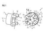
- FIGS. 1 to 4 show a dog clutch 1 according to an embodiment of the present invention or components thereof.
- the jaw clutch 1 serves to transmit a torque between two aligned shafts and comprises as main components two in the intended mounted state axially oppositely disposed coupling elements 2, 3 with aligned longitudinal axes A1, A2 and arranged between these pressure ring 4.
- the two coupling elements 2 and 3 have mutually facing and arched formed end faces 5 and 6, of which mutually interlocking claws 7 and 8 protrude, which are each arranged on corresponding circular rings, each coupling element 2, 3 present four claws 7, the eighth having.
- adjacently arranged claws 7 and 8 of the coupling elements 2 and 3 define therebetween an axially extending receiving space 9, which is bounded by mutually facing concavely curved side surfaces 10 and 11 of the claws 7 and 8 of the coupling elements 2 and 3 in the circumferential direction.
- the coupling elements 2 and 3 are presently identical. Alternatively, it is of course also possible to form the coupling elements 2 and 3 and their claws 7 and 8 differently, if this is expedient.
- the pressure ring 4 is made of elastic material and comprises a ring member 12 and eight radially outwardly of the ring member 12 projecting pressure body 13, wherein the ring member 12 and the pressure body 13 are formed integrally in the present case.
- the pressure bodies 13 comprise surfaces 14 which are convexly curved, the bulges essentially following those of the jaws 7 and 8.
- Each pressure body 13 is provided on one of its opposite end faces 15 with an axially projecting spacer 16, which defines a longitudinally oval in the radial direction formed flat contact surface 17, wherein the spacers 16 adjacent pressure body 13 each protrude axially in opposite directions.
- the pressure ring 4 is inserted between the two coupling elements 2 and 3 such that the individual pressure body 13 of the pressure body ring 4 are received in the respective receiving spaces 9, each between the facing side surfaces 10 and 11 of the jaws 7 and 8 are defined.
- the 13 of the pressure bodies above Spacer 16 from the end faces 5 and 6 of the coupling elements 2 and 3 slightly spaced.
- the curvature of the end faces 5 and 6 of the coupling elements 2 and 3 is selected so that in the unloaded state of the dog clutch 1, an axial distance a between the contact surfaces 17 of the spacers 16 and the end faces 5, 6 and their contact surface areas in a radial outward direction R increases as it is in FIG. 2 is indicated by the indicated distances a1 and a2.
- the end faces 5 and 6 of the coupling elements 2 and 3 may also have an inclination instead of the described curvature.
- the shape and position of the spacers 16 may vary. So, for example each pressure body 13 may be provided with two spacers 16 projecting in opposite directions from the pressure bodies 13.
- the abutment surfaces 17 of the spacers 16 may be inclined or arched, in particular corresponding to the contact surface areas of the end faces 5 and 6.
Abstract
Description
- Die vorliegende Erfindung betrifft eine Klauenkupplung umfassend zwei einander gegenüber und bezogen auf eine Längsachse fluchtend angeordnete Kupplungselemente mit einander zugewandten Stirnflächen, von denen jeweils wechselweise ineinander greifende Klauen vorstehen, die jeweils auf Kreisringen angeordnet sind, und einen zwischen den beiden Kupplungselementen angeordneten, aus elastischem Material hergestellten Druckkörperring, der ein Ringelement sowie radial auswärts von dem Ringelement vorstehende Druckkörper aufweist, von denen jeder zwischen zwei benachbart angeordneten Klauen der jeweiligen Kupplungselemente aufgenommen ist, wobei zumindest einige der Druckkörper mit wenigstens einem axial vorstehenden Abstandshalter versehen sind, und wobei jeder Abstandshalter eine Anlagefläche aufweist, die, wenn über die Klauenkupplung ein vorbestimmtes Drehmoment übertragen wird, gegen einen Kontaktflächenbereich einer Stirnfläche eines Kupplungselements gedrückt wird.
- Klauenkupplungen der eingangs genannten Art sind im Stand der Technik in unterschiedlichsten Ausgestaltungen bekannt. Sie dienen dazu, ein Drehmoment zwischen zwei miteinander fluchtenden Wellen zu übertragen, wie beispielsweise zwischen einer Motorwelle und einer Getriebewelle. Während des Betriebs verdrehen sich die beiden Kupplungselemente relativ zueinander entsprechend dem anliegenden Drehmoment und der Steifigkeit des elastischen Materials des Druckkörperringes. Dabei vollzieht auch jede Klaue der Kupplungselemente eine Drehbewegung, wobei sich ein radial weiter außen angeordneter Punkt einer Seitenfläche einer Klaue auf einer größeren Kreisbahn als ein weiter innen liegender Punkt auf der Seitenfläche der Klaue bewegt und damit einen größeren Weg zurücklegt. Dies führt dazu, dass jeder Druckkörper des Druckkörperringes außen mehr zusammengepresst wird als innen, was eine ungleichförmige Pressungsverteilung nach sich zieht, bei der radial außen eine höhere Kantenpressung wirkt. Entsprechend werden die Druckkörper während des Betriebs der Klauenkupplung radial einwärts gedrückt, was häufig eine erhebliche und unerwünschte Verformung des Ringelementes des Druckkörperringes nach sich zieht. Um derartige Verformungen des Ringelementes zu verhindern, ist es bereits bekannt, das maximal zulässige Drehmoment einer Klauenkupplung zu begrenzen. Auf diese Weise kann verhindert werden, dass unzulässig hohe radial einwärts gerichtete Kräfte auf die Druckkörper wirken, wodurch einer Verformung des Ringelementes des Druckkörperringes effektiv entgegen gewirkt werden kann. Das maximal zulässige Drehmoment ist hier allerdings meist sehr niedrig anzusetzen. Ein weiterer Ansatz besteht darin, das Ringelement des Druckkörperringes durch eine Kreisscheibe zu ersetzen, um der Anordnung eine höhere Steifigkeit in radialer Richtung zu verleihen. Bei einer solchen Ausgestaltung kann dann eine Welle jedoch nicht mehr in die Klauenkupplung ragen, was eine konstruktive Einschränkung bedeutet.
- Ausgehend von diesem Stand der Technik ist es eine Aufgabe der vorliegenden Erfindung, eine Klauenkupplung der eingangs genannten Art mit alternativem Aufbau zu schaffen.
- Zur Lösung dieser Aufgabe schafft die vorliegende Erfindung eine Klauenkupplung der eingangs genannten Art, die dadurch gekennzeichnet ist, dass die Kontaktflächenbereiche derart geneigt oder gewölbt ausgebildet sind, dass im unbelasteten Zustand der Klauenkupplung ein axialer Abstand zwischen den Anlageflächen der Abstandshalter und den zugeordneten Kontaktflächenbereichen der Stirnflächen in radialer Auswärtsrichtung zunimmt. Während einer Drehmomentübertragung von einem Kupplungselement zum anderen Kupplungselement werden die Druckkörper des Druckkörperringes derart verformt, dass sich die Stirnflächen der jeweiligen Druckkörper mit den an diesen angeordneten Abstandshaltern ausbauchen, bis die Anlageflächen der Abstandshalter bei Überschreitung eines vorbestimmten Drehmomentes mit den Kontaktflächenbereichen der Stirnflächen der Kupplungselemente in Eingriff kommen, wodurch wie bei herkömmlichen Abstandshaltern zunächst eine axiale Fixierung der Druckkörper erzielt wird. Bei weiterer Erhöhung des Drehmomentes werden die Anlageflächen dann gegen die Kontaktflächenbereiche gedrückt, was eine Verformung der Abstandshalter zur Folge hat. Dank der geneigten oder gewölbten Ausbildung der Kontaktflächenbereiche der Stirnflächen der Kupplungselemente werden die sich verformenden Abstandshalter zusammen mit den Druckkörpern, von denen sie vorstehen, an einer radialen Einwärtsbewegung gehindert, wodurch das Ringelement des Druckkörperringes entlastet wird. Auf diese Weise wird einer Verformung des Ringelementes des Druckkörperringes in radialer Einwärtsrichtung effektiv entgegen gewirkt.
- Gemäß einer Ausgestaltung der vorliegenden Erfindung weist jedes Kupplungselement vier Klauen und der Druckkörperring acht Druckkörper auf. Diese Ausgestaltung hat sich hinsichtlich einer Drehmomentübertragung als sehr vorteilhaft erwiesen.
- Bevorzugt ist jeder Druckkörper mit zumindest einem Abstandshalter versehen. Dies ist dahingehend von Vorteil, dass auftretende Kräfte gleichmäßig über den Druckkörperring verteilt werden.
- Gemäß einer Ausgestaltung der vorliegenden Erfindung stehen Abstandshalter benachbarter Druckkörper axial in entgegengesetzten Richtungen vor. Auch diese Ausgestaltung ist einer gleichmäßigen Kraftverteilung zuträglich.
- Vorteilhaft ist jeder Druckkörper mit zumindest zwei Abstandshaltern versehen, die in entgegengesetzten Richtungen vorstehen.
- Gemäß einer Ausgestaltung der vorliegenden Erfindung sind die Anlageflächen der Abstandshalter geneigt oder gewölbt ausgebildet, insbesondere korrespondierend zu den Kontaktflächenbereichen der Stirnflächen der Kupplungselemente.
- Bevorzugt sind die Anlageflächen der Abstandshalter in radialer Richtung länglich, insbesondere oval ausgebildet, wodurch während des Betriebs der Klauenkupplung vergleichsweise große, radial auswärts gerichtete Kräfte erzeugt werden.
- Weitere Merkmale und Vorteile der vorliegenden Erfindung werden anhand der nachfolgenden Beschreibung einer Klauenkupplung gemäß einer Ausführungsform der vorliegenden Erfindung unter Bezugnahme auf die beiliegende Zeichnung deutlich. Darin ist
- Figur 1
- eine perspektivische Ansicht einer Klauenkupplung gemäß einer Ausführungsform der vorliegenden Erfindung in teilweise montiertem Zustand;
- Figur 2
- eine geschnittene Seitenansicht des in
Figur 1 gezeigten Kupplungselementes entlang der Linie II inFigur 1 , wobei sich die dargestellte Anordnung in einem unbelasteten Zustand befindet; - Figur 3
- eine geschnittene Seitenansicht anlag zu
Figur 2 , wobei sich die Anordnung in einem Zustand befindet, in dem ein vorbestimmtes Drehmoment übertragen wird; und - Figur 4
- eine geschnittene Seitenansicht analog zu
Figur 2 , wobei sich die Anordnung in einem Zustand befindet, in dem ein Nenn-Drehmoment der Klauenkupplung übertragen wird. - Die
Figuren 1 bis 4 zeigen eine Klauenkupplung 1 gemäß eine Ausführungsform der vorliegenden Erfindung bzw. Komponenten derselben. Die Klauenkupplung 1 dient dazu, ein Drehmoment zwischen zwei miteinander fluchtenden Wellen zu übertragen und umfasst als Hauptkomponenten zwei im bestimmungsgemäß montierten Zustand axial einander gegenüber angeordnete Kupplungselemente 2, 3 mit fluchtenden Längsachsen A1, A2 sowie einen zwischen diesen angeordneten Druckkörperring 4. - Die beiden Kupplungselemente 2 und 3 weisen einander zugewandte und gewölbt ausgebildete Stirnflächen 5 und 6 auf, von denen wechselweise ineinander greifende Klauen 7 und 8 vorstehen, die jeweils auf einander entsprechenden Kreisringen angeordnet sind, wobei jedes Kupplungselement 2, 3 vorliegend vier Klauen 7, 8 aufweist. Dabei definieren jeweils benachbart angeordnete Klauen 7 und 8 der Kupplungselemente 2 und 3 zwischen sich einen sich axial erstreckenden Aufnahmeraum 9, der von einander zugewandten konkav gewölbten Seitenflächen 10 und 11 der Klauen 7 und 8 der Kupplungselemente 2 und 3 in Umfangsrichtung begrenzt ist. Die Kupplungselemente 2 und 3 sind vorliegend identisch ausgebildet. Alternativ ist es natürlich auch möglich, die Kupplungselemente 2 und 3 sowie deren Klauen 7 und 8 verschieden auszubilden, wenn dies zweckdienlich ist.
- Der Druckkörperring 4 ist aus elastischem Material hergestellt und umfasst ein Ringelement 12 sowie acht radial auswärts von dem Ringelement 12 vorstehende Druckkörper 13, wobei das Ringelement 12 und die Druckkörper 13 vorliegend einteilig ausgebildet sind. Die Druckkörper 13 umfassen Flächen 14, die konvex gewölbt sind, wobei die Wölbungen im Wesentlichen denjenigen der Klauen 7 und 8 folgen. Jeder Druckkörper 13 ist an einer seiner gegenüberliegenden Stirnseiten 15 mit einem axial vorstehenden Abstandshalter 16 versehen, der eine in radialer Richtung länglich oval ausgebildete ebene Anlagefläche 17 definiert, wobei die Abstandshalter 16 benachbarter Druckkörper 13 jeweils axial in entgegengesetzten Richtungen vorstehen.
- Im montierten Zustand der Klauenkupplung 1 ist der Druckkörperring 4 zwischen den beiden Kupplungselementen 2 und 3 derart eingesetzt, dass die einzelnen Druckkörper 13 des Druckkörperringes 4 in den jeweiligen Aufnahmeräumen 9 aufgenommen sind, die jeweils zwischen den einander zugewandten Seitenflächen 10 und 11 der Klauen 7 und 8 definiert sind. Im unbelasteten Zustand der Klauenkupplung 1, der in den
Figur 2 dargestellt ist, sind die von den Druckkörpern 13 vorstehenden Abstandshalter 16 von den Stirnflächen 5 und 6 der Kupplungselemente 2 und 3 leicht beabstandet. Die Wölbung der Stirnflächen 5 und 6 der Kupplungselemente 2 und 3 ist derart gewählt, dass im unbelasteten Zustand der Klauenkupplung 1 ein axialer Abstand a zwischen den Anlagenflächen 17 der Abstandhalter 16 und den Stirnflächen 5, 6 bzw. deren Kontaktflächenbereichen in einer radialen Auswärtsrichtung R zunimmt, wie es inFigur 2 durch die eingezeichneten Abstände a1 und a2 angedeutet ist. - Wird von der Klauenkupplung 1 nunmehr ein Drehmoment übertragen, so werden die zwischen den Klauen 7 und 8 der Kupplungselemente 2 und 3 aufgenommenen Druckkörper 13 derart verformt, dass sich die Stirnseiten 15 der Druckkörper 13 ausbauchen. Bei Erreichen eines vorbestimmten Drehmomentes kommen die Anlageflächen 17 der Abstandshalter 16 dann mit Kontaktflächenbereichen der Stirnflächen 5 und 6 der Kupplungselemente 2 und 3 nach und nach in Kontakt, wie es in der Figur 3 dargestellt ist. Wird das Drehmoment ausgehend von diesem Zustand weiter erhöht, beispielsweise auf das Nenn-Drehmoment der Klauenkupplung 1, so drücken die Anlageflächen 17 der einzelnen Druckkörper 13 vollständig gegen Kontaktflächenbereiche der Stirnflächen 5 und 6 der Kupplungselemente 2 und 3, wie es in der
Figur 4 gezeigt ist, wobei dank der Wölbung der Stirnflächen 5 und 6 verhindert wird, dass das Ringelement 12 des Druckkörperringes 4 in radialer Einwärtsrichtung verformt wird, da die Abstandshalter 16 an einer Bewegung in radialer Einwärtsrichtung gehindert werden. - Obwohl die Erfindung im Detail durch das bevorzugte Ausführungsbeispiel näher illustriert und beschrieben wurde, so ist die Erfindung nicht durch die offenbarten Beispiele eingeschränkt und andere Variationen können vom Fachmann hieraus abgeleitet werden, ohne den Schutzumfang der Erfindung zu verlassen. Insbesondere können die Stirnflächen 5 und 6 der Kupplungselemente 2 und 3 anstelle der beschriebenen Wölbung auch eine Neigung aufweisen. Ferner können die Form und Position der Abstandshalter 16 variieren. So kann beispielsweise jeder Druckkörper 13 mit zwei Abstandshaltern 16 versehen sein, die in entgegengesetzte Richtungen von den Druckkörpern 13 vorstehen. Zudem können auch die Anlageflächen 17 der Abstandshalter 16 geneigt oder gewölbt ausgebildet sein, insbesondere korrespondierend zu den Kontaktflächenbereichen der Stirnflächen 5 und 6.
Claims (7)
- Klauenkupplung (1) umfassend zwei einander gegenüber und bezogen auf eine Längsachse (A) fluchtend angeordnete Kupplungselemente (2, 3) mit einander zugewandten Stirnflächen (5, 6), von denen jeweils wechselweise ineinander greifende Klauen (7, 8) vorstehen, die jeweils auf Kreisringen angeordnet sind, und einen zwischen den beiden Kupplungselementen (2, 3) angeordneten, aus elastischem Material hergestellten Druckkörperring (4), der ein Ringelement (12) sowie radial auswärts von dem Ringelement (12) vorstehende Druckkörper (13) aufweist, von denen jeder zwischen zwei benachbart angeordneten Klauen (7, 8) der jeweiligen Kupplungselemente (2, 3) aufgenommen ist, wobei zumindest einige der Druckkörper (13) mit wenigstens einem axial vorstehenden Abstandshalter (16) versehen sind, und wobei jeder Abstandshalter (16) eine Anlagefläche (17) aufweist, die, wenn über die Klauenkupplung (1) ein vorbestimmtes Drehmoment übertragen wird, gegen einen Kontaktflächenbereich einer Stirnfläche (5, 6) eines Kupplungselements (2, 3) gedrückt wird, dadurch gekennzeichnet, dass im unbelasteten Zustand der Klauenkupplung (1) ein axialer Abstand (a) zwischen den Anlageflächen (17) der Abstandshalter (16) und den zugeordneten Kontaktflächenbereichen der Stirnfläche (5, 6) in radialer Auswärtsrichtung (R) zunimmt.
- Klauenkupplung (1) nach Anspruch 1, dadurch gekennzeichnet, dass jedes Kupplungselement (2, 3) vier Klauen (7, 8) und der Druckkörperring (4) acht Druckkörper (13) aufweist.
- Klauenkupplung (1) nach einem der vorhergehenden Ansprüche, dadurch gekennzeichnet, dass jeder Druckkörper (13) mit zumindest einem Abstandshalter (16) versehen ist.
- Klauenkupplung (1) nach Anspruch 3, dadurch gekennzeichnet, dass Abstandshalter (16) benachbarter Druckkörper (13) axial in entgegengesetzten Richtungen vorstehen.
- Klauenkupplung (1) nach Anspruch 3 oder 4, dadurch gekennzeichnet, dass jeder Druckkörper (13) mit zumindest zwei Abstandshaltern (16) versehen ist, die in entgegengesetzten Richtungen vorstehen.
- Klauenkupplung (1) nach einem der vorhergehenden Ansprüche, dadurch gekennzeichnet, dass die Anlageflächen (17) der Abstandshalter (16) geneigt oder gewölbt ausgebildet sind, insbesondere korrespondierend zu den Kontaktflächenbereichen der Stirnflächen (5, 6) der Kupplungselemente (2, 3).
- Klauenkupplung (1) nach einem der vorhergehenden Ansprüche, dadurch gekennzeichnet, dass die Anlageflächen (17) der Abstandshalter (16) in radialer Richtung länglich, insbesondere oval ausgebildet sind.
Priority Applications (4)
| Application Number | Priority Date | Filing Date | Title |
|---|---|---|---|
| ES15001280T ES2743774T3 (es) | 2015-04-30 | 2015-04-30 | Acoplamiento de garras |
| EP15001280.5A EP3088757B1 (de) | 2015-04-30 | 2015-04-30 | Klauenkupplung |
| CN201610258057.0A CN106090052B (zh) | 2015-04-30 | 2016-04-21 | 爪式离合器 |
| US15/142,727 US10087993B2 (en) | 2015-04-30 | 2016-04-29 | Claw coupling |
Applications Claiming Priority (1)
| Application Number | Priority Date | Filing Date | Title |
|---|---|---|---|
| EP15001280.5A EP3088757B1 (de) | 2015-04-30 | 2015-04-30 | Klauenkupplung |
Publications (2)
| Publication Number | Publication Date |
|---|---|
| EP3088757A1 true EP3088757A1 (de) | 2016-11-02 |
| EP3088757B1 EP3088757B1 (de) | 2019-05-29 |
Family
ID=53040339
Family Applications (1)
| Application Number | Title | Priority Date | Filing Date |
|---|---|---|---|
| EP15001280.5A Active EP3088757B1 (de) | 2015-04-30 | 2015-04-30 | Klauenkupplung |
Country Status (4)
| Country | Link |
|---|---|
| US (1) | US10087993B2 (de) |
| EP (1) | EP3088757B1 (de) |
| CN (1) | CN106090052B (de) |
| ES (1) | ES2743774T3 (de) |
Cited By (1)
| Publication number | Priority date | Publication date | Assignee | Title |
|---|---|---|---|---|
| EP3974671A1 (de) * | 2020-09-25 | 2022-03-30 | Flender GmbH | Verbesserte kupplung für industrie-applikationen und schienenfahrzeug |
Families Citing this family (5)
| Publication number | Priority date | Publication date | Assignee | Title |
|---|---|---|---|---|
| JP6544654B2 (ja) * | 2016-09-05 | 2019-07-17 | Smc株式会社 | 弾性軸継手 |
| US10138947B2 (en) * | 2017-02-16 | 2018-11-27 | GM Global Technology Operations LLC | Radially applied dog clutch with bi-directional ratcheting for a vehicle transmission |
| CN106864756A (zh) * | 2017-03-27 | 2017-06-20 | 必扬星环(北京)航空科技有限公司 | 无人直升机双余度涡轮轴动力系统 |
| EP3385558B1 (de) | 2017-04-07 | 2019-12-04 | Flender GmbH | Lamellenkupplung |
| CN112334673B (zh) * | 2018-06-22 | 2023-08-08 | 索尤若驱动有限及两合公司 | 具有柱体区域和轴向突出区域的部件以及制造该部件的方法 |
Citations (3)
| Publication number | Priority date | Publication date | Assignee | Title |
|---|---|---|---|---|
| JPS58211022A (ja) * | 1982-05-24 | 1983-12-08 | カツプリングステクニ−ク・ゲ−・エム・ベ−・ハ− | かみあわせカツプリング |
| US6123620A (en) * | 1998-08-18 | 2000-09-26 | Brunswick Corporation | Multirate coupler with improved vibration isolation capability |
| EP2500594A1 (de) * | 2009-11-10 | 2012-09-19 | Oiles Corporation | Wellenkupplungsmechanismus |
Family Cites Families (5)
| Publication number | Priority date | Publication date | Assignee | Title |
|---|---|---|---|---|
| US2706897A (en) * | 1953-04-17 | 1955-04-26 | Holoye Jules Alfred | Elastic coupling device for connecting two shafts in line with each other |
| FR1104652A (fr) * | 1954-07-15 | 1955-11-23 | Joint élastique pour l'accouplement d'arbres coaxiaux | |
| DE29622017U1 (de) * | 1996-12-18 | 1997-02-06 | Gerwah Praezision Gmbh | Kupplung mit elastischem Mitnehmerelement |
| DE29806632U1 (de) * | 1998-04-11 | 1998-08-20 | Kupplungstechnik Gmbh | Drehelastische Klauenkupplung |
| JP4779356B2 (ja) * | 2004-12-24 | 2011-09-28 | オイレス工業株式会社 | 電動式パワーステアリング装置用の軸連結機構 |
-
2015
- 2015-04-30 EP EP15001280.5A patent/EP3088757B1/de active Active
- 2015-04-30 ES ES15001280T patent/ES2743774T3/es active Active
-
2016
- 2016-04-21 CN CN201610258057.0A patent/CN106090052B/zh active Active
- 2016-04-29 US US15/142,727 patent/US10087993B2/en active Active
Patent Citations (3)
| Publication number | Priority date | Publication date | Assignee | Title |
|---|---|---|---|---|
| JPS58211022A (ja) * | 1982-05-24 | 1983-12-08 | カツプリングステクニ−ク・ゲ−・エム・ベ−・ハ− | かみあわせカツプリング |
| US6123620A (en) * | 1998-08-18 | 2000-09-26 | Brunswick Corporation | Multirate coupler with improved vibration isolation capability |
| EP2500594A1 (de) * | 2009-11-10 | 2012-09-19 | Oiles Corporation | Wellenkupplungsmechanismus |
Cited By (4)
| Publication number | Priority date | Publication date | Assignee | Title |
|---|---|---|---|---|
| EP3974671A1 (de) * | 2020-09-25 | 2022-03-30 | Flender GmbH | Verbesserte kupplung für industrie-applikationen und schienenfahrzeug |
| WO2022063691A1 (de) | 2020-09-25 | 2022-03-31 | Flender Gmbh | Verbesserte kupplung für industrie-applikationen und schienenfahrzeug |
| EP4217620A1 (de) * | 2020-09-25 | 2023-08-02 | Flender GmbH | Verbesserte kupplung für industrie-applikationen und schienenfahrzeug |
| US11920641B2 (en) | 2020-09-25 | 2024-03-05 | Flender Gmbh | Coupling for industrial applications, and rail vehicle |
Also Published As
| Publication number | Publication date |
|---|---|
| EP3088757B1 (de) | 2019-05-29 |
| CN106090052B (zh) | 2019-05-28 |
| ES2743774T3 (es) | 2020-02-20 |
| US20160319886A1 (en) | 2016-11-03 |
| US10087993B2 (en) | 2018-10-02 |
| CN106090052A (zh) | 2016-11-09 |
Similar Documents
| Publication | Publication Date | Title |
|---|---|---|
| EP3088757B1 (de) | Klauenkupplung | |
| DE3536886C2 (de) | Drehmoment-Begrenzungseinrichtung | |
| EP0931966A1 (de) | Spannbare Rohrkupplung | |
| DE1475519A1 (de) | Flexible Kupplung | |
| DE112011102928T5 (de) | Toleranzring für Drehmomentübertragungsvorrichtung | |
| EP2940364B1 (de) | Schlauchkupplung | |
| DE102008028396A1 (de) | Verbindungsanordnung und Gelenkwelle hiermit | |
| DE2653007C2 (de) | Kupplung zur Verbindung einer antreibenden mit einer angetriebenen Welle | |
| DE112007003190T5 (de) | Gelenkanordnung mit Käfigversatz | |
| DD252862A5 (de) | Elastische wellenkupplung | |
| EP3088756B1 (de) | Klauenkupplung | |
| DE102009034018A1 (de) | Wälzlager | |
| DE3642438A1 (de) | Anordnung mit einem axialen haltekoerper | |
| DE19707138C2 (de) | Gelenkscheibe aus Faserverbundwerkstoff | |
| DE102018122194A1 (de) | Kupplungseinrichtung | |
| EP3088758B1 (de) | Druckkörperanordnung für eine klauenkupplung | |
| DE10335514B4 (de) | Rohrverbindung | |
| DE19919686A1 (de) | Flexible Kupplung mit elastomerem Transmissionsband | |
| EP1574732A1 (de) | Spannvorrichtung zum lösbaren Festspannen einer zylindrischen Nabe auf einer zylindrischen Welle | |
| DE2920074A1 (de) | Elastische kupplung | |
| DE4332142C1 (de) | Schlingfederkupplung für zwei fluchtende Wellen | |
| DE102014114460A1 (de) | Anordnung für eine Wellenkupplung | |
| EP3440369B1 (de) | Elastische wellenkupplung | |
| DE202008010765U1 (de) | Wellenkupplung | |
| DE202020104448U1 (de) | Walzensegment, Walze und landwirtschaftliche Ernteguttransport- und/oder Reinigungsvorrichtung |
Legal Events
| Date | Code | Title | Description |
|---|---|---|---|
| PUAI | Public reference made under article 153(3) epc to a published international application that has entered the european phase |
Free format text: ORIGINAL CODE: 0009012 |
|
| AK | Designated contracting states |
Kind code of ref document: A1 Designated state(s): AL AT BE BG CH CY CZ DE DK EE ES FI FR GB GR HR HU IE IS IT LI LT LU LV MC MK MT NL NO PL PT RO RS SE SI SK SM TR |
|
| AX | Request for extension of the european patent |
Extension state: BA ME |
|
| STAA | Information on the status of an ep patent application or granted ep patent |
Free format text: STATUS: REQUEST FOR EXAMINATION WAS MADE |
|
| 17P | Request for examination filed |
Effective date: 20161121 |
|
| RBV | Designated contracting states (corrected) |
Designated state(s): AL AT BE BG CH CY CZ DE DK EE ES FI FR GB GR HR HU IE IS IT LI LT LU LV MC MK MT NL NO PL PT RO RS SE SI SK SM TR |
|
| RAP1 | Party data changed (applicant data changed or rights of an application transferred) |
Owner name: SIEMENS AKTIENGESELLSCHAFT |
|
| RAP1 | Party data changed (applicant data changed or rights of an application transferred) |
Owner name: FLENDER GMBH |
|
| GRAP | Despatch of communication of intention to grant a patent |
Free format text: ORIGINAL CODE: EPIDOSNIGR1 |
|
| STAA | Information on the status of an ep patent application or granted ep patent |
Free format text: STATUS: GRANT OF PATENT IS INTENDED |
|
| INTG | Intention to grant announced |
Effective date: 20190103 |
|
| GRAS | Grant fee paid |
Free format text: ORIGINAL CODE: EPIDOSNIGR3 |
|
| GRAA | (expected) grant |
Free format text: ORIGINAL CODE: 0009210 |
|
| STAA | Information on the status of an ep patent application or granted ep patent |
Free format text: STATUS: THE PATENT HAS BEEN GRANTED |
|
| AK | Designated contracting states |
Kind code of ref document: B1 Designated state(s): AL AT BE BG CH CY CZ DE DK EE ES FI FR GB GR HR HU IE IS IT LI LT LU LV MC MK MT NL NO PL PT RO RS SE SI SK SM TR |
|
| REG | Reference to a national code |
Ref country code: GB Ref legal event code: FG4D Free format text: NOT ENGLISH |
|
| REG | Reference to a national code |
Ref country code: CH Ref legal event code: EP |
|
| REG | Reference to a national code |
Ref country code: DE Ref legal event code: R096 Ref document number: 502015009157 Country of ref document: DE |
|
| REG | Reference to a national code |
Ref country code: AT Ref legal event code: REF Ref document number: 1138444 Country of ref document: AT Kind code of ref document: T Effective date: 20190615 |
|
| REG | Reference to a national code |
Ref country code: IE Ref legal event code: FG4D Free format text: LANGUAGE OF EP DOCUMENT: GERMAN |
|
| REG | Reference to a national code |
Ref country code: NL Ref legal event code: MP Effective date: 20190529 |
|
| REG | Reference to a national code |
Ref country code: LT Ref legal event code: MG4D |
|
| PG25 | Lapsed in a contracting state [announced via postgrant information from national office to epo] |
Ref country code: LT Free format text: LAPSE BECAUSE OF FAILURE TO SUBMIT A TRANSLATION OF THE DESCRIPTION OR TO PAY THE FEE WITHIN THE PRESCRIBED TIME-LIMIT Effective date: 20190529 Ref country code: HR Free format text: LAPSE BECAUSE OF FAILURE TO SUBMIT A TRANSLATION OF THE DESCRIPTION OR TO PAY THE FEE WITHIN THE PRESCRIBED TIME-LIMIT Effective date: 20190529 Ref country code: PT Free format text: LAPSE BECAUSE OF FAILURE TO SUBMIT A TRANSLATION OF THE DESCRIPTION OR TO PAY THE FEE WITHIN THE PRESCRIBED TIME-LIMIT Effective date: 20190930 Ref country code: NO Free format text: LAPSE BECAUSE OF FAILURE TO SUBMIT A TRANSLATION OF THE DESCRIPTION OR TO PAY THE FEE WITHIN THE PRESCRIBED TIME-LIMIT Effective date: 20190829 Ref country code: SE Free format text: LAPSE BECAUSE OF FAILURE TO SUBMIT A TRANSLATION OF THE DESCRIPTION OR TO PAY THE FEE WITHIN THE PRESCRIBED TIME-LIMIT Effective date: 20190529 Ref country code: AL Free format text: LAPSE BECAUSE OF FAILURE TO SUBMIT A TRANSLATION OF THE DESCRIPTION OR TO PAY THE FEE WITHIN THE PRESCRIBED TIME-LIMIT Effective date: 20190529 |
|
| PG25 | Lapsed in a contracting state [announced via postgrant information from national office to epo] |
Ref country code: BG Free format text: LAPSE BECAUSE OF FAILURE TO SUBMIT A TRANSLATION OF THE DESCRIPTION OR TO PAY THE FEE WITHIN THE PRESCRIBED TIME-LIMIT Effective date: 20190829 Ref country code: LV Free format text: LAPSE BECAUSE OF FAILURE TO SUBMIT A TRANSLATION OF THE DESCRIPTION OR TO PAY THE FEE WITHIN THE PRESCRIBED TIME-LIMIT Effective date: 20190529 Ref country code: RS Free format text: LAPSE BECAUSE OF FAILURE TO SUBMIT A TRANSLATION OF THE DESCRIPTION OR TO PAY THE FEE WITHIN THE PRESCRIBED TIME-LIMIT Effective date: 20190529 Ref country code: GR Free format text: LAPSE BECAUSE OF FAILURE TO SUBMIT A TRANSLATION OF THE DESCRIPTION OR TO PAY THE FEE WITHIN THE PRESCRIBED TIME-LIMIT Effective date: 20190830 |
|
| PG25 | Lapsed in a contracting state [announced via postgrant information from national office to epo] |
Ref country code: EE Free format text: LAPSE BECAUSE OF FAILURE TO SUBMIT A TRANSLATION OF THE DESCRIPTION OR TO PAY THE FEE WITHIN THE PRESCRIBED TIME-LIMIT Effective date: 20190529 Ref country code: NL Free format text: LAPSE BECAUSE OF FAILURE TO SUBMIT A TRANSLATION OF THE DESCRIPTION OR TO PAY THE FEE WITHIN THE PRESCRIBED TIME-LIMIT Effective date: 20190529 Ref country code: SK Free format text: LAPSE BECAUSE OF FAILURE TO SUBMIT A TRANSLATION OF THE DESCRIPTION OR TO PAY THE FEE WITHIN THE PRESCRIBED TIME-LIMIT Effective date: 20190529 Ref country code: CZ Free format text: LAPSE BECAUSE OF FAILURE TO SUBMIT A TRANSLATION OF THE DESCRIPTION OR TO PAY THE FEE WITHIN THE PRESCRIBED TIME-LIMIT Effective date: 20190529 Ref country code: RO Free format text: LAPSE BECAUSE OF FAILURE TO SUBMIT A TRANSLATION OF THE DESCRIPTION OR TO PAY THE FEE WITHIN THE PRESCRIBED TIME-LIMIT Effective date: 20190529 Ref country code: DK Free format text: LAPSE BECAUSE OF FAILURE TO SUBMIT A TRANSLATION OF THE DESCRIPTION OR TO PAY THE FEE WITHIN THE PRESCRIBED TIME-LIMIT Effective date: 20190529 |
|
| PG25 | Lapsed in a contracting state [announced via postgrant information from national office to epo] |
Ref country code: SM Free format text: LAPSE BECAUSE OF FAILURE TO SUBMIT A TRANSLATION OF THE DESCRIPTION OR TO PAY THE FEE WITHIN THE PRESCRIBED TIME-LIMIT Effective date: 20190529 |
|
| REG | Reference to a national code |
Ref country code: DE Ref legal event code: R097 Ref document number: 502015009157 Country of ref document: DE |
|
| PG25 | Lapsed in a contracting state [announced via postgrant information from national office to epo] |
Ref country code: TR Free format text: LAPSE BECAUSE OF FAILURE TO SUBMIT A TRANSLATION OF THE DESCRIPTION OR TO PAY THE FEE WITHIN THE PRESCRIBED TIME-LIMIT Effective date: 20190529 |
|
| PLBE | No opposition filed within time limit |
Free format text: ORIGINAL CODE: 0009261 |
|
| STAA | Information on the status of an ep patent application or granted ep patent |
Free format text: STATUS: NO OPPOSITION FILED WITHIN TIME LIMIT |
|
| PG25 | Lapsed in a contracting state [announced via postgrant information from national office to epo] |
Ref country code: PL Free format text: LAPSE BECAUSE OF FAILURE TO SUBMIT A TRANSLATION OF THE DESCRIPTION OR TO PAY THE FEE WITHIN THE PRESCRIBED TIME-LIMIT Effective date: 20190529 |
|
| 26N | No opposition filed |
Effective date: 20200303 |
|
| PG25 | Lapsed in a contracting state [announced via postgrant information from national office to epo] |
Ref country code: SI Free format text: LAPSE BECAUSE OF FAILURE TO SUBMIT A TRANSLATION OF THE DESCRIPTION OR TO PAY THE FEE WITHIN THE PRESCRIBED TIME-LIMIT Effective date: 20190529 |
|
| PG25 | Lapsed in a contracting state [announced via postgrant information from national office to epo] |
Ref country code: MC Free format text: LAPSE BECAUSE OF FAILURE TO SUBMIT A TRANSLATION OF THE DESCRIPTION OR TO PAY THE FEE WITHIN THE PRESCRIBED TIME-LIMIT Effective date: 20190529 |
|
| REG | Reference to a national code |
Ref country code: CH Ref legal event code: PL |
|
| PG25 | Lapsed in a contracting state [announced via postgrant information from national office to epo] |
Ref country code: CH Free format text: LAPSE BECAUSE OF NON-PAYMENT OF DUE FEES Effective date: 20200430 Ref country code: LU Free format text: LAPSE BECAUSE OF NON-PAYMENT OF DUE FEES Effective date: 20200430 Ref country code: LI Free format text: LAPSE BECAUSE OF NON-PAYMENT OF DUE FEES Effective date: 20200430 |
|
| PG25 | Lapsed in a contracting state [announced via postgrant information from national office to epo] |
Ref country code: IE Free format text: LAPSE BECAUSE OF NON-PAYMENT OF DUE FEES Effective date: 20200430 |
|
| REG | Reference to a national code |
Ref country code: DE Ref legal event code: R082 Ref document number: 502015009157 Country of ref document: DE Representative=s name: MICHALSKI HUETTERMANN & PARTNER PATENTANWAELTE, DE |
|
| REG | Reference to a national code |
Ref country code: AT Ref legal event code: MM01 Ref document number: 1138444 Country of ref document: AT Kind code of ref document: T Effective date: 20200430 |
|
| PG25 | Lapsed in a contracting state [announced via postgrant information from national office to epo] |
Ref country code: AT Free format text: LAPSE BECAUSE OF NON-PAYMENT OF DUE FEES Effective date: 20200430 |
|
| PG25 | Lapsed in a contracting state [announced via postgrant information from national office to epo] |
Ref country code: MT Free format text: LAPSE BECAUSE OF FAILURE TO SUBMIT A TRANSLATION OF THE DESCRIPTION OR TO PAY THE FEE WITHIN THE PRESCRIBED TIME-LIMIT Effective date: 20190529 Ref country code: CY Free format text: LAPSE BECAUSE OF FAILURE TO SUBMIT A TRANSLATION OF THE DESCRIPTION OR TO PAY THE FEE WITHIN THE PRESCRIBED TIME-LIMIT Effective date: 20190529 |
|
| PG25 | Lapsed in a contracting state [announced via postgrant information from national office to epo] |
Ref country code: MK Free format text: LAPSE BECAUSE OF FAILURE TO SUBMIT A TRANSLATION OF THE DESCRIPTION OR TO PAY THE FEE WITHIN THE PRESCRIBED TIME-LIMIT Effective date: 20190529 Ref country code: IS Free format text: LAPSE BECAUSE OF FAILURE TO SUBMIT A TRANSLATION OF THE DESCRIPTION OR TO PAY THE FEE WITHIN THE PRESCRIBED TIME-LIMIT Effective date: 20190929 |
|
| PGFP | Annual fee paid to national office [announced via postgrant information from national office to epo] |
Ref country code: IT Payment date: 20230426 Year of fee payment: 9 Ref country code: FR Payment date: 20230424 Year of fee payment: 9 Ref country code: ES Payment date: 20230627 Year of fee payment: 9 Ref country code: DE Payment date: 20230426 Year of fee payment: 9 |
|
| PGFP | Annual fee paid to national office [announced via postgrant information from national office to epo] |
Ref country code: FI Payment date: 20230419 Year of fee payment: 9 |
|
| PGFP | Annual fee paid to national office [announced via postgrant information from national office to epo] |
Ref country code: BE Payment date: 20230419 Year of fee payment: 9 |
|
| PGFP | Annual fee paid to national office [announced via postgrant information from national office to epo] |
Ref country code: GB Payment date: 20230419 Year of fee payment: 9 |