EP3088729B1 - Kraftstoffinjektor sowie vorrichtung und verfahren zur montage einer messeinrichtung - Google Patents
Kraftstoffinjektor sowie vorrichtung und verfahren zur montage einer messeinrichtung Download PDFInfo
- Publication number
- EP3088729B1 EP3088729B1 EP16165757.2A EP16165757A EP3088729B1 EP 3088729 B1 EP3088729 B1 EP 3088729B1 EP 16165757 A EP16165757 A EP 16165757A EP 3088729 B1 EP3088729 B1 EP 3088729B1
- Authority
- EP
- European Patent Office
- Prior art keywords
- housing
- injector
- sensor element
- housing element
- sensor
- Prior art date
- Legal status (The legal status is an assumption and is not a legal conclusion. Google has not performed a legal analysis and makes no representation as to the accuracy of the status listed.)
- Active
Links
- 239000000446 fuel Substances 0.000 title claims description 47
- 238000000034 method Methods 0.000 title claims description 9
- 238000002485 combustion reaction Methods 0.000 claims description 13
- 238000002347 injection Methods 0.000 claims description 11
- 239000007924 injection Substances 0.000 claims description 11
- 239000002184 metal Substances 0.000 claims description 4
- 230000005489 elastic deformation Effects 0.000 claims 1
- 239000010410 layer Substances 0.000 description 10
- 239000000853 adhesive Substances 0.000 description 3
- 230000001070 adhesive effect Effects 0.000 description 3
- 238000009413 insulation Methods 0.000 description 3
- 238000004519 manufacturing process Methods 0.000 description 3
- 230000036316 preload Effects 0.000 description 3
- 239000012790 adhesive layer Substances 0.000 description 2
- 238000011156 evaluation Methods 0.000 description 2
- 238000007789 sealing Methods 0.000 description 2
- 240000001439 Opuntia Species 0.000 description 1
- 235000004727 Opuntia ficus indica Nutrition 0.000 description 1
- 230000015572 biosynthetic process Effects 0.000 description 1
- 150000001875 compounds Chemical class 0.000 description 1
- 238000010276 construction Methods 0.000 description 1
- 238000011161 development Methods 0.000 description 1
- 230000018109 developmental process Effects 0.000 description 1
- 239000012528 membrane Substances 0.000 description 1
- 230000002093 peripheral effect Effects 0.000 description 1
- 238000003856 thermoforming Methods 0.000 description 1
Images
Classifications
-
- F—MECHANICAL ENGINEERING; LIGHTING; HEATING; WEAPONS; BLASTING
- F02—COMBUSTION ENGINES; HOT-GAS OR COMBUSTION-PRODUCT ENGINE PLANTS
- F02M—SUPPLYING COMBUSTION ENGINES IN GENERAL WITH COMBUSTIBLE MIXTURES OR CONSTITUENTS THEREOF
- F02M57/00—Fuel-injectors combined or associated with other devices
- F02M57/005—Fuel-injectors combined or associated with other devices the devices being sensors
-
- F—MECHANICAL ENGINEERING; LIGHTING; HEATING; WEAPONS; BLASTING
- F02—COMBUSTION ENGINES; HOT-GAS OR COMBUSTION-PRODUCT ENGINE PLANTS
- F02M—SUPPLYING COMBUSTION ENGINES IN GENERAL WITH COMBUSTIBLE MIXTURES OR CONSTITUENTS THEREOF
- F02M65/00—Testing fuel-injection apparatus, e.g. testing injection timing ; Cleaning of fuel-injection apparatus
- F02M65/003—Measuring variation of fuel pressure in high pressure line
-
- F—MECHANICAL ENGINEERING; LIGHTING; HEATING; WEAPONS; BLASTING
- F02—COMBUSTION ENGINES; HOT-GAS OR COMBUSTION-PRODUCT ENGINE PLANTS
- F02M—SUPPLYING COMBUSTION ENGINES IN GENERAL WITH COMBUSTIBLE MIXTURES OR CONSTITUENTS THEREOF
- F02M2200/00—Details of fuel-injection apparatus, not otherwise provided for
- F02M2200/21—Fuel-injection apparatus with piezoelectric or magnetostrictive elements
-
- F—MECHANICAL ENGINEERING; LIGHTING; HEATING; WEAPONS; BLASTING
- F02—COMBUSTION ENGINES; HOT-GAS OR COMBUSTION-PRODUCT ENGINE PLANTS
- F02M—SUPPLYING COMBUSTION ENGINES IN GENERAL WITH COMBUSTIBLE MIXTURES OR CONSTITUENTS THEREOF
- F02M2200/00—Details of fuel-injection apparatus, not otherwise provided for
- F02M2200/24—Fuel-injection apparatus with sensors
- F02M2200/242—Displacement sensors
-
- F—MECHANICAL ENGINEERING; LIGHTING; HEATING; WEAPONS; BLASTING
- F02—COMBUSTION ENGINES; HOT-GAS OR COMBUSTION-PRODUCT ENGINE PLANTS
- F02M—SUPPLYING COMBUSTION ENGINES IN GENERAL WITH COMBUSTIBLE MIXTURES OR CONSTITUENTS THEREOF
- F02M2200/00—Details of fuel-injection apparatus, not otherwise provided for
- F02M2200/24—Fuel-injection apparatus with sensors
- F02M2200/244—Force sensors
-
- F—MECHANICAL ENGINEERING; LIGHTING; HEATING; WEAPONS; BLASTING
- F02—COMBUSTION ENGINES; HOT-GAS OR COMBUSTION-PRODUCT ENGINE PLANTS
- F02M—SUPPLYING COMBUSTION ENGINES IN GENERAL WITH COMBUSTIBLE MIXTURES OR CONSTITUENTS THEREOF
- F02M2200/00—Details of fuel-injection apparatus, not otherwise provided for
- F02M2200/24—Fuel-injection apparatus with sensors
- F02M2200/247—Pressure sensors
-
- F—MECHANICAL ENGINEERING; LIGHTING; HEATING; WEAPONS; BLASTING
- F02—COMBUSTION ENGINES; HOT-GAS OR COMBUSTION-PRODUCT ENGINE PLANTS
- F02M—SUPPLYING COMBUSTION ENGINES IN GENERAL WITH COMBUSTIBLE MIXTURES OR CONSTITUENTS THEREOF
- F02M2200/00—Details of fuel-injection apparatus, not otherwise provided for
- F02M2200/80—Fuel injection apparatus manufacture, repair or assembly
- F02M2200/8076—Fuel injection apparatus manufacture, repair or assembly involving threaded members
-
- F—MECHANICAL ENGINEERING; LIGHTING; HEATING; WEAPONS; BLASTING
- F02—COMBUSTION ENGINES; HOT-GAS OR COMBUSTION-PRODUCT ENGINE PLANTS
- F02M—SUPPLYING COMBUSTION ENGINES IN GENERAL WITH COMBUSTIBLE MIXTURES OR CONSTITUENTS THEREOF
- F02M2200/00—Details of fuel-injection apparatus, not otherwise provided for
- F02M2200/80—Fuel injection apparatus manufacture, repair or assembly
- F02M2200/8084—Fuel injection apparatus manufacture, repair or assembly involving welding or soldering
Definitions
- the invention relates to a fuel injector according to the preamble of claim 1. Furthermore, the invention relates to an apparatus and method for mounting a measuring device.
- a fuel injector according to the preamble of claim 1 is from the post-published DE 10 2015 206 029 A1 the applicant known.
- Kraftstoffinjektor is used to detect the closing time of the nozzle needle, wherein this hits its seat in the injector and thereby at least indirectly closes injection openings formed in the injector, using a measuring device with a sensor element designed as a piezoelectric element, which is arranged in the region of a supply bore on the injector , The supply bore supplies a high-pressure space, in which the nozzle needle is arranged, with fuel under high pressure.
- the injector housing has a deformation region which is designed to be elastically deformable as a function of the fuel pressure in the supply bore.
- the measuring device has a closed, multi-part housing in which the sensor element or the piezoelectric element is arranged.
- the sensor housing is in turn directly connected in particular by means of a welded connection with the deformation region.
- the piezoelectric element is arranged within the sensor housing under axial prestress, for which purpose the sensor housing has two housing elements which are adjustable relative to each other in the axial force direction and which are fixed to one another in the installed state by means of a weld seam.
- the axial force acted upon piezoelectric element are in particular reduced or equalized tensile stresses that can reduce the life of the piezoelectric element.
- Characteristic of the known fuel injector or its sensor device is moreover that the piezoelectric element does not lie directly on the surface of the injector housing or rests, but is separated by a housing bottom of the sensor housing of the injector.
- DE 19813756 discloses a fuel injector wherein the sensor element is held by a Fixierhohlschraube in a blind hole.
- the present invention seeks to form a fuel injector such that waiving an adhesive bond between the piezo element or the sensor element and the injector a reliable as possible over the entire service life of the fuel injector working arrangement of a measuring device is made possible.
- tensile stresses on the piezoceramic, which can damage the piezoceramic should also be avoided.
- a fuel injector with the characterizing features of claim 1, characterized in that the sensor element with its deformation region facing end face rests directly on the deformation region, and that the means for adjusting the biasing force comprises a sensor housing with two housing elements movable relative to each other, which are rigidly connected together in an assembled position at least in the direction of the axial force acting on the piezoelectric element.
- the two housing elements are arranged in the overlapping area with a joining play each other and welded together.
- the joining play can be designed in the form of a friction fit between the two housing elements, in order to be able to form a welded joint relatively easily even with housing elements having relatively small wall thicknesses, since no (large) gaps have to be bridged.
- connection between the two housing elements it may also be provided that the two housing elements are connected to one another in the overlapping area by means of a threaded connection.
- an additional connection between the two housing elements such as a weld, can be dispensed with, so that the manufacturing process can possibly be simplified compared with the use of a weld seam.
- the housing elements in contrast to a welded joint, are not thermally stressed in the formation of the compound.
- a first housing element has a flange-like connection area on the side facing the injector housing for engagement with the injector housing.
- a second housing element is arranged radially inside the sleeve-shaped housing element.
- a second housing element which may be formed in particular in the form of a disc or a lid, is thus arranged completely within the contour of the first-mentioned, sleeve-shaped housing element and therefore particularly particularly well protected.
- a second housing element may be hood-shaped and to comprise the sleeve-shaped housing element on its outer surface with a radially peripheral edge region.
- the housing elements are made of metal and that a housing member is connected to the injector by means of a welded joint.
- the invention also includes a device for mounting the measuring or sensor device for a fuel injector described so far, wherein the device comprises a support body with a blind hole-like recess, wherein the recess is adapted to receive the sensor element partially, such that the sensor element at least indirectly rests on the bottom of the recess, wherein the recess is bounded by a contact surface for a housing element, and wherein the recess has a depth corresponding to a difference measure for adjusting the axial biasing force on the sensor element.
- Such a device is thus suitable to position the two housing elements to each other in a position in which in the assembled state of Housing elements on the injector body which is received within the housing elements sensor element with the appropriate axial biasing force against the deformation region of the injector.
- a device makes it possible to compensate for manufacturing or tolerance-related geometric differences between the housing elements and / or sensor elements in a particularly simple manner.
- a sensor device is arranged in the region of the recess of a support body. Subsequently, the arrangement of a first housing element takes place radially around the sensor element, wherein the first housing element rests on a contact surface of the support body. Subsequently, an axial joining of a second housing element takes place relative to the first housing element until the second housing element is at least indirectly in abutting contact with the sensor element. Finally, if necessary, a fixing of the second housing element to the first housing element takes place.
- the invention comprises a method for mounting a sensor device in a fuel injector according to the invention, the method having at least the following steps: First, a first housing element is fastened to an injector housing. Subsequently, the sensor element is arranged within the first housing element such that the sensor element bears against a surface of the injector housing. Thereafter, the mounting of a second housing element on the first housing element takes place such that the second housing element is arranged at least indirectly in abutting contact with the sensor element. This is followed by the generation of an axial prestressing force on the second housing element and finally possibly fixing of the second housing element to the first housing element.
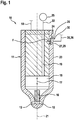
- the Indian Fig. 1 fuel injector 10 shown greatly simplified is designed as a so-called common rail injector, and is used to inject fuel into the combustion chamber, not shown, of an internal combustion engine, in particular a self-igniting internal combustion engine.
- the fuel injector 10 has an injector housing 11, which consists essentially of metal and may have a multi-part design, in which at least one, preferably several injection openings 12 for injecting the fuel are arranged on the side facing the combustion chamber of the internal combustion engine.
- this forms a high pressure chamber 15, in which a nozzle needle 16 serving as an injection member is arranged in a liftable manner in the direction of the double arrow 17.
- a nozzle needle 16 serving as an injection member is arranged in a liftable manner in the direction of the double arrow 17.
- this forms together with the inner wall of the high-pressure chamber 15 and the injector 11 a sealing seat, so that the injection openings 12 are at least indirectly closed, such that the injection of fuel from the high-pressure chamber 15 in the Combustion chamber of the internal combustion engine is avoided.
- the nozzle needle 16 In the other, not shown, lifted from the sealing seat position of the nozzle needle 16, this releases the injection openings 12 for injecting the fuel into the combustion chamber of the internal combustion engine.
- the movement of the nozzle needle 16, in particular for releasing the injection openings 12, takes place in a manner known per se by means of an actuator, not shown, which can be actuated via a voltage supply line 18 by a control device of the internal combustion engine.
- the actuator may in particular be a magnetic actuator or else a piezoactuator.
- the supply bore 19 is also connected via a fuel connection, not shown, with a fuel line 22, which in turn is coupled to a fuel reservoir 25 (rail).
- axially relatively widely spaced portion of the injector 11 is in the outer wall 23 by way of example a blind hole-shaped recess 24 is formed, so that the wall thickness of the injector 11 is reduced in the region of the recess 24.
- the injector housing 11 may also have a flattening, in the region of which the wall thickness of the injector housing 11 is reduced.
- the newly formed base 26 of the recess 24 forms part of a deformation region 27.
- the fuel pressure currently prevailing in the supply bore 19 also acts in the injector housing 11 on the side facing away from the recess 24.
- the wall section 29 of the injector housing 11 acts on the recess 24 facing side as a deformation region 27 in the manner of an elastically deformable membrane, wherein the deformation, which forms as a curvature, the higher, the higher the instantaneous fuel pressure in the supply bore 19 is.
- the fuel injector 10 For detecting the time profile of the fuel pressure in the supply bore 19 and thus also in the high-pressure chamber 15, which is used as an indication of the instantaneous position of the nozzle needle 16 for driving the nozzle needle 16, the fuel injector 10 has a measuring device 30.
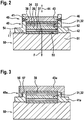
- the measuring device 30 comprises according to the Fig. 2 a sensor element 32 designed as a piezo element 31.
- the sensor element 32 has, by way of example, two electrode layers 33, 34 arranged parallel to one another, which by means of only in FIG Fig. 1 recognizable connecting wires 35, 36 are connected for example to an evaluation device, not shown, such that upon deformation of the deformation region 27 of the piezoelectric element 31 electrical voltages are generated, which are supplied via the connecting wires 35, 36 of the evaluation circuit as an input.
- an evaluation device not shown
- thermoforming sensor housing 40 comprises according to presentation of the Fig. 2 a substantially sleeve-shaped and rotationally symmetrical formed first housing element 41, in which the sensor element 32 is arranged with only a small radial gap.
- first housing element 41 assigned to the injector housing 11
- the latter has a radially encircling connection region 42 in the form of a fastening flange, which extends radially outside the sleeve-shaped region of the first housing element 41.
- a second, disk-shaped or cover-shaped housing element 43 is arranged radially inside the first housing element 41.
- the outer diameter or the cross section of the second housing element 43 is adapted to the inner diameter or the inner cross section of the first housing member 41, that the second housing member 43 is disposed axially displaceable or adjustable within the first housing member 41 in the direction of the double arrow 44, preferably with only (minor) leadership game.
- a radially encircling weld seam 46 is provided, which extends at the level of the second housing element 43 ,
- a device 50 which comprises a block-shaped support body 51.
- a blind hole-shaped recess 52 is formed, the base surface or cross section of the base surface or the cross section of the sensor element 32 is adapted such that the one insulation layer 37 over the entire surface 53 of the recess 52 rests.
- the recess 52 is bounded radially by a contact surface 54, on which the connecting region 42 of the first housing element 41 rests.
- the depth t of the recess 52 in the device 50 is dimensioned such that the depth t corresponds to the difference dimension for setting the axial preload force F on the sensor element 32.
- the second housing element 43 is thus within a first housing element 41 arranged and positioned and secured with the first housing member 41 (by means of the weld 45) that the second insulating layer 38 facing end face of the second housing member 43 rests against the second insulating layer 38 of the piezoelectric element 31.
- the sensor housing 40 manufactured so far can be fastened with sensor element 32 arranged therein on the surface of the deformation area 27, preferably by means of a weld (not shown) in the connection area 42 of the first housing member 41, wherein the connecting portion 42 is in abutting contact with the connecting portion 27.
- the sensor housing 40 is axially elastically deformed by the elasticity of the two housing elements 41, 43 so that the desired axial biasing force F is generated on the piezoelectric element 31, wherein the piezoelectric element 31 and the sensor element 32 with the insulating layer 37 directly to the base 26 of Recess 24 is present.
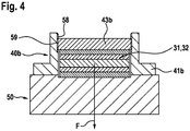
- the first housing element 41a has an external thread 56 on its outer circumference, which cooperates with an internal thread 57 formed on the cover-shaped or hat-shaped second housing element 43a.
- the external thread 56 and the internal thread 57 are preferably as Fine thread formed to allow a sensitive adjustment of the biasing force F. It is also essential that the position between the two housing elements 41a, 43a is not adjusted by itself after setting the biasing force F or the position is fixed. This can possibly be ensured by means of additional measures (adhesive, caulking etc.).
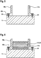
- the sensor housing 40b has a first housing element 41b which on its inner circumference at least in some areas has an internal thread 58 which is connected to a second housing element 43b on a housing Outer circumference formed external thread 59 cooperates.
- an axial adjustment of the two housing elements 41b, 43b relative to one another can be achieved by a corresponding rotation of the second housing element 43b relative to the first housing element 41b, in order to allow abutment of the second housing element 43b on the insulation layer 38 of the piezoelement 31.
- the first housing element 41, 41a, 41b has no flange-like circumferential connection region 42, but is in the form of a constant diameter sleeve having.
- a first housing element 41c which is formed for example in analogy to the first housing member 41a with an external thread 56c over the connection region 42c is brought into abutting contact with the outer wall 23 of the injector housing 11 in the region of the deformation region 27. Then, the first housing element 41c in the connection region 42c is connected to the injector housing 11 via a weld 61. Subsequently, according to the illustration of the Fig. 6 arranging the piezo element 31 or the sensor element 32 within the first housing element 41c.
- the required axial preload force F is generated on the piezo element 31.
- the piezoelectric element 31 is connected via the connecting wires 35, 36 with a measuring device 63 which is adapted to detect the electrical voltages of the piezoelectric element 31 generated due to the axial biasing force F.
- the corresponding voltage signals of the piezoelectric element 31 thus serve as a measure of the relative positioning of the two housing elements 41c, 43c to each other until the desired axial preload force F is achieved.
Description
- Die Erfindung betrifft einen Kraftstoffinjektor nach dem Oberbegriff des Anspruchs 1. Ferner betrifft die Erfindung eine Vorrichtung und Verfahren zur Montage einer Messeinrichtung.
- Ein Kraftstoffinjektor nach dem Oberbegriff des Anspruchs 1 ist aus der nachveröffentlichten
DE 10 2015 206 029 A1 der Anmelderin bekannt. Bei dem bekannten Kraftstoffinjektor wird zur Detektion des Schließzeitpunkts der Düsennadel, bei dem diese auf ihren Sitz im Injektorgehäuse auftrifft und dadurch im Injektorgehäuse ausgebildete Einspritzöffnungen zumindest mittelbar verschließt, eine Messeinrichtung mit einem als Piezoelement ausgebildeten Sensorelement verwendet, das im Bereich einer Versorgungsbohrung am Injektorgehäuse angeordnet ist. Die Versorgungsbohrung versorgt einen Hochdruckraum, in dem auch die Düsennadel angeordnet ist, mit unter Hochdruck stehendem Kraftstoff. Das Injektorgehäuse weist im Bereich der Messeinrichtung einen Verformungsbereich auf, der in Abhängigkeit des Kraftstoffdrucks in der Versorgungsbohrung elastisch deformierbar ausgebildet ist. Bei einer Druckerhöhung in der Versorgungsbohrung wölbt sich der Verformungsbereich elastisch nach außen, was mittels des Piezoelements detektierbar ist. Die Messeinrichtung weist bei dem bekannten Kraftstoffinjektor ein geschlossenes, mehrteilig ausgebildetes Gehäuse auf, in dem das Sensorelement bzw. das Piezoelement angeordnet ist. Das Sensorgehäuse ist wiederum insbesondere mittels einer Schweißverbindung mit dem Verformungsbereich unmittelbar verbunden. Darüber hinaus ist das Piezoelement innerhalb des Sensorgehäuses unter axialer Vorspannung angeordnet, wozu das Sensorgehäuse zwei in Richtung der Axialkraft relativ zueinander verstellbare bzw. bewegliche Gehäuseelemente aufweist, die im Einbauzustand mittels einer Schweißnaht zueinander fixiert sind. Durch das mit der Axialkraft beaufschlagte Piezoelement werden insbesondere Zugspannungen reduziert bzw. egalisiert, die die Lebensdauer des Piezoelements herabsetzen können. Charakteristisch bei dem bekannten Kraftstoffinjektor bzw. dessen Sensoreinrichtung ist darüber hinaus, dass das Piezoelement nicht unmittelbar an der Oberfläche des Injektorgehäuses aufliegt bzw. anliegt, sondern durch einen Gehäuseboden des Sensorgehäuses von dem Injektorgehäuse getrennt ist. - Darüber hinaus ist es aus der nachveröffentlichten
DE 10 2014 209 330 A1 bekannt, ein Sensorelement ohne Verwendung eines Gehäuses mittels einer Klebstoffschicht mit dem Verformungsbereich des Injektorgehäuses zu verbinden. Die Verwendung einer derartigen Klebstoffschicht ist jedoch insofern problematisch, als dass insbesondere über die Betriebsdauer des Kraftstoffinjektors betrachtet die Beständigkeit bzw. Dauerfestigkeit der Klebeverbindung in der Praxis relativ schwierig zu realisieren ist. -
DE 19813756 offenbart einen Kraftstoffinjektor wobei das Sensorelement durch eine Fixierhohlschraube in einem Sackloch gehalten wird. - Ausgehend von dem dargestellten Stand der Technik liegt der Erfindung die Aufgabe zugrunde, einen Kraftstoffinjektor derart auszubilden, dass bei Verzicht auf eine Klebeverbindung zwischen dem Piezoelement bzw. dem Sensorelement und dem Injektorgehäuse eine möglichst einfache, über die gesamte Betriebs- bzw. Lebensdauer des Kraftstoffinjektors zuverlässig arbeitende Anordnung einer Messeinrichtung ermöglicht wird. Insbesondere sollen auch Zugbelastungen auf die Piezokeramik, welche die Piezokeramik schädigen können, vermieden werden.
- Diese Aufgabe wird erfindungsgemäß bei einem Kraftstoffinjektor mit den kennzeichnenden Merkmalen des Anspruchs 1 dadurch gelöst, dass das Sensorelement mit seiner dem Verformungsbereich zugewandten Stirnseite unmittelbar auf dem Verformungsbereich aufliegt, und dass die Einrichtung zur Einstellung der Vorspannkraft ein Sensorgehäuse mit zwei relativ zueinander bewegliche Gehäuseelemente umfasst, die in einer gefügten Stellung zumindest in Richtung der auf das Piezoelement wirkenden Axialkraft starr miteinander verbunden sind. Ein derartig ausgebildeter Kraftstoffinjektor hat darüber hinaus den besonderen Vorteil, dass er hinsichtlich seiner Bauhöhe besonders kompakt baut und das Sensorgehäuse im Vergleich zum Stand der Technik konstruktiv einfacher gestaltet werden kann.
- Vorteilhafte Weiterbildungen des erfindungsgemäßen Kraftstoffinjektors sind in den Unteransprüchen aufgeführt.
- Um einerseits ein möglichst kompakt bauendes Sensorgehäuse auszubilden, und andererseits eine dichte und feste Verbindung der beiden Gehäuseelemente zu ermöglichen, ist es besonders bevorzugt vorgesehen, dass die beiden Gehäuseelemente im Überlappungsbereich mit einem Fügespiel zueinander angeordnet und miteinander verschweißt sind. Das Fügespiel kann dabei in Form einer Reibpassung zwischen den beiden Gehäuseelementen ausgebildet sein, um insbesondere auch bei relativ geringe Wandstärken aufweisenden Gehäuseelementen relativ einfach eine Schweißverbindung ausbilden zu können, da keine (großen) Spalte überbrückt werden müssen.
- In alternativer konstruktiver Ausbildung der Verbindung zwischen den beiden Gehäuseelementen kann es jedoch auch vorgesehen sein, dass die beiden Gehäuseelemente im Überlappungsbereich mittels einer Gewindeverbindung miteinander verbunden sind. Dadurch kann insbesondere auf eine zusätzliche Verbindung zwischen den beiden Gehäuseelementen wie eine Schweißnaht verzichtet werden, so dass der Fertigungsprozess gegenüber der Verwendung einer Schweißnaht ggf. vereinfacht werden kann. Auch werden die Gehäuseelemente, im Gegensatz zu einer Schweißverbindung, bei der Ausbildung der Verbindung thermisch nicht beansprucht.
- Zur Verbindung des Sensorgehäuses mit dem Injektorgehäuse ist es insbesondere vorgesehen, dass ein erstes Gehäuseelement auf der dem Injektorgehäuse zugewandten Seite einen flanschartigen Verbindungsbereich zur Anlage an das Injektorgehäuse aufweist. Mittels eines derartigen Verbindungsbereichs lässt sich insbesondere mittels einer Schweißverbindung eine einfache, genaue und feste Verbindung zwischen dem Sensorgehäuse und dem Injektorgehäuse ermöglichen. Erfindungsgemäß ist es vorgesehen, dass eines der Gehäuseelemente hülsenförmig ausgebildet ist, und dass das Sensorelement innerhalb des hülsenförmigen Gehäuseelements mit radialem Führungsspiel angeordnet ist. Dadurch wird insbesondere auch ein relativ kompakter Aufbau des Sensorgehäuses ermöglicht. Erfindungsgemäß ist es vorgesehen, dass ein zweites Gehäuseelement radial innerhalb des hülsenförmigen Gehäuseelements angeordnet ist. Ein derartiges zweites Gehäuseelement, das insbesondere in Form einer Scheibe bzw. eines Deckels ausgebildet sein kann, ist somit vollständig innerhalb der Kontur des zuerst genannten, hülsenförmigen Gehäuseelements und daher insbesondere besonders gut geschützt angeordnet.
- Alternativ ist es jedoch auch möglich, dass ein zweites Gehäuseelement haubenförmig ausgebildet ist und mit einem radial umlaufenden Randbereich das hülsenförmige Gehäuseelement an seiner Außenfläche umfasst.
- Um einerseits eine möglichst einfache und preiswerte Herstellung und andererseits eine hohe Temperaturbeständigkeit der Gehäuseelemente sowie eine einfache Verbindung mit dem Injektorgehäuse zu ermöglichen, ist es vorgesehen, dass die Gehäuseelemente aus Metall bestehen und dass ein Gehäuseelement mit dem Injektorgehäuse mittels einer Schweißverbindung verbunden ist.
- Die Erfindung umfasst auch eine Vorrichtung zur Montage der Meß- bzw. Sensoreinrichtung für einen soweit beschriebenen erfindungsgemäßen Kraftstoffinjektor, wobei die Vorrichtung einen Auflagekörper mit einer sacklochartigen Ausnehmung umfasst, wobei die Ausnehmung dazu ausgebildet ist, das Sensorelement bereichsweise aufzunehmen, derart, dass das Sensorelement zumindest mittelbar am Grund der Ausnehmung aufliegt, wobei die Ausnehmung von einer Anlagefläche für ein Gehäuseelement begrenzt ist, und wobei die Ausnehmung eine Tiefe aufweist, die einem Differenzmaß zur Einstellung der axialen Vorspannkraft auf das Sensorelement entspricht. Eine derartige Vorrichtung ist damit geeignet, die beiden Gehäuseelemente zueinander in eine Position zu positionieren, bei der im montierten Zustand der Gehäuseelemente an dem Injektorkörper das innerhalb der Gehäuseelemente aufgenommene Sensorelement mit der dafür vorgesehenen axialen Vorspannkraft gegen den Verformungsbereich des Injektorgehäuses anliegt. Insbesondere ermöglicht es eine derartige Vorrichtung, fertigungs- bzw. toleranzbedingte geometrische Unterschiede zwischen den Gehäuseelementen und/oder Sensorelementen auf besonders einfache Art und Weise auszugleichen.
- Bei einem Verfahren zur Montage einer Sensoreinrichtung mittels einer soweit beschriebenen Vorrichtung sind zumindest folgende Schritte vorgesehen: Zunächst wird eine Sensoreinrichtung im Bereich der Ausnehmung eines Auflagekörpers angeordnet. Anschließend erfolgt das Anordnen eines ersten Gehäuseelements radial um das Sensorelement, wobei das erste Gehäuseelement an einer Anlagefläche des Auflagekörpers aufliegt. Anschließend erfolgt ein axiales Fügen eines zweiten Gehäuseelements relativ zum ersten Gehäuseelement, bis das zweite Gehäuseelement zumindest mittelbar in Anlagekontakt mit dem Sensorelement ist. Zuletzt erfolgt ggf. ein Fixieren des zweiten Gehäuseelements zum ersten Gehäuseelement.
- Darüber hinaus umfasst die Erfindung ein Verfahren zur Montage einer Sensoreinrichtung bei einem erfindungsgemäßen Kraftstoffinjektor, wobei das Verfahren zumindest folgende Schritte aufweist: Zunächst wird ein erstes Gehäuseelement an einem Injektorgehäuse befestigt. Anschließend erfolgt das Anordnen des Sensorelements innerhalb des ersten Gehäuseelements derart, dass das Sensorelement an einer Fläche des Injektorgehäuses anliegt. Danach erfolgt die Montage eines zweiten Gehäuseelements am ersten Gehäuseelement derart, dass das zweite Gehäuseelement zumindest mittelbar in Anlagekontakt mit dem Sensorelement angeordnet ist. Darauf folgt das Erzeugen einer axialen Vorspannkraft auf das zweite Gehäuseelement und zuletzt ggf. ein Fixieren des zweiten Gehäuseelements zum ersten Gehäuseelement.
- Insbesondere zur genauen Einstellung der erforderlichen axialen Einspannkraft bzw. Vorspannkraft auf das Sensorelement zwischen den beiden Gehäuseelementen ist es vorgesehen, dass ein von dem Sensorelement erzeugtes Spannungssignal während des Aufbringens der axialen Vorspannkraft überwacht wird.
- Weitere Vorteile, Merkmale und Einzelheiten der Erfindung ergeben sich aus der nachfolgenden Beschreibung bevorzugter Ausführungsbeispiele sowie anhand der Zeichnung.
- Diese zeigt in:
- Fig. 1
- eine stark vereinfachte, teilweise geschnittene Seitenansicht eines erfindungsgemäßen Kraftstoffinjektors mit einer Messeinrichtung zur zumindest mittelbaren Erfassung des Kraftstoffdrucks im Kraftstoffinjektor,
- Fig. 2:
- eine Vorrichtung zur Montage der bei dem Kraftstoffinjektor gemäß
Fig. 1 verwendeten Messeinrichtung in einem Längsschnitt, - Fig. 3 und Fig. 4
- gegenüber der
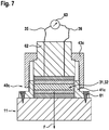
Fig. 2 abgewandelte Messeinrichtungen unter Verwendung einer Gewindeverbindung zwischen zwei Gehäuseelementen der Messeinrichtung, jeweils im Längsschnitt und - Fig. 5 bis Fig. 7
- jeweils in einem Längsschnitt unterschiedliche Montageschritte zur Befestigung einer Messeinrichtung an einem Injektorgehäuse des Kraftstoffinjektors gemäß
Fig. 1 . - Gleiche Elemente bzw. Elemente mit gleicher Funktion sind in den Figuren mit den gleichen Bezugsziffern versehen.
- Der in der
Fig. 1 stark vereinfacht dargestellte Kraftstoffinjektor 10 ist als sogenannter Common-Rail-Injektor ausgebildet, und dient dem Einspritzen von Kraftstoff in den nicht gezeigten Brennraum einer Brennkraftmaschine, insbesondere einer selbstzündenden Brennkraftmaschine. - Der Kraftstoffinjektor 10 weist ein im Wesentlichen aus Metall bestehendes, ggf. mehrteilig ausgebildetes Injektorgehäuse 11 auf, in dem auf der dem Brennraum der Brennkraftmaschine zugewandten Seite wenigstens eine, vorzugsweise mehrere Einspritzöffnungen 12 zum Einspritzen des Kraftstoffs angeordnet sind. Innerhalb des Injektorgehäuses 11 bildet dieses einen Hochruckraum 15 aus, in dem eine als Einspritzglied dienende Düsennadel 16 in Richtung des Doppelpfeils 17 hubbeweglich angeordnet ist. In der dargestellten, abgesenkten Stellung der Düsennadel 16 bildet diese zusammen mit der Innenwand des Hochdruckraums 15 bzw. des Injektorgehäuses 11 einen Dichtsitz aus, so dass die Einspritzöffnungen 12 zumindest mittelbar verschlossen sind, derart, dass das Einspritzen von Kraftstoff aus dem Hochdruckraum 15 in den Brennraum der Brennkraftmaschine vermieden wird. In der anderen, nicht dargestellten, von dem Dichtsitz abgehobenen Position der Düsennadel 16 gibt diese die Einspritzöffnungen 12 zum Einspritzen des Kraftstoffs in den Brennraum der Brennkraftmaschine frei. Die Bewegung der Düsennadel 16, insbesondere zum Freigeben der Einspritzöffnungen 12, erfolgt auf eine an sich bekannte Art und Weise mittels eines nicht dargestellten Aktuators, der über eine Spannungsversorgungsleitung 18 von einer Steuereinrichtung der Brennkraftmaschine ansteuerbar ist. Bei dem Aktuator kann es sich insbesondere um einen Magnetaktuator oder aber um einen Piezoaktuator handeln.
- Die Versorgung des Hochdruckraums 15 mit unter Hochdruck (Systemdruck) stehendem Kraftstoff erfolgt über eine innerhalb des Injektorgehäuses 11 angeordnete bzw. in Bauteilen des Kraftstoffinjektors 10 ausgebildete Versorgungsbohrung 19, die insbesondere exzentrisch zur Längsachse 21 des Injektorgehäuses 11 in einem Randbereich des Kraftstoffinjektors 10, zumindest im Wesentlichen parallel zur Längsachse 21, verläuft. Die Versorgungsbohrung 19 ist darüber hinaus über einen nicht dargestellten Kraftstoffanschlussstutzen mit einer Kraftstoffleitung 22 verbunden, welche wiederum mit einem Kraftstoffspeicher 25 (Rail) gekoppelt ist.
- In einem von den Einspritzöffnungen 12 bzw. dem Brennraum axial relativ weit beabstandeten Bereich des Injektorgehäuses 11 ist in dessen Außenwand 23 beispielhaft eine sacklochförmige Vertiefung 24 ausgebildet, so dass die Wanddicke des Injektorgehäuses 11 im Bereich der Vertiefung 24 reduziert ist.
- Ergänzend wird erwähnt, dass anstelle einer sacklochförmigen Vertiefung 24 das Injektorgehäuse 11 auch eine Abflachung aufweisen kann, in deren Bereich die Wanddicke des Injektorgehäuses 11 reduziert ist.
- Der eben ausgebildete Grund 26 der Vertiefung 24 bildet einen Teil eines Verformungsbereichs 27 aus. Dadurch wirkt der in der Versorgungsbohrung 19 augenblicklich herrschende Kraftstoffdruck auch in dem Injektorgehäuse 11 auf der der Vertiefung 24 abgewandten Seite. Dadurch, dass die Wanddicke des Injektorgehäuses 11 im Bereich der Vertiefung 24 reduziert ist, wirkt der Wandabschnitt 29 des Injektorgehäuses 11 auf der der Vertiefung 24 zugewandten Seite als Verformungsbereich 27 in Art einer elastisch verformbaren Membran, wobei die Verformung, welche sich als Wölbung ausbildet, umso größer ist, je höher der augenblickliche Kraftstoffdruck in der Versorgungsbohrung 19 ist.
- Zur Detektion des zeitlichen Verlaufs des Kraftstoffdrucks in der Versorgungsbohrung 19 und damit auch in dem Hochdruckraum 15, welcher als Indiz für die augenblickliche Stellung der Düsennadel 16 zur Ansteuerung der Düsennadel 16 verwendet wird, weist der Kraftstoffinjektor 10 eine Messeinrichtung 30 auf. Die Messeinrichtung 30 umfasst entsprechend der
Fig. 2 ein als Piezoelement 31 ausgebildetes Sensorelement 32. - Das Sensorelement 32 weist neben einer Piezokeramikschicht 28 beispielhaft zwei, parallel zueinander angeordnete Elektrodenschichten 33, 34 auf, die mittels lediglich in der
Fig. 1 erkennbarer Anschlussdrähte 35, 36 beispielsweise mit einer nicht dargestellten Auswerteeinrichtung verbunden sind, derart, dass bei einer Deformation des Verformungsbereichs 27 von dem Piezoelement 31 elektrische Spannungen erzeugt werden, die über die Anschlussdrähte 35, 36 der Auswerteschaltung als Eingangsgröße zugeführt werden. Auf den einander abgewandten Stirnflächen der Elektrodenschichten 33, 34 sind diese jeweils mit einer elektrisch nichtleitenden Isolationsschicht 37, 38 vollflächig überdeckt. - Das soweit beschriebene, insbesondere zylindrische bzw. blockförmig ausgebildete Piezoelement 31 ist innerhalb eines vorzugsweise aus Metall bestehenden, zumindest teilweise im Tiefziehverfahren ausgebildeten Sensorgehäuses 40 angeordnet. Das Sensorgehäuse 40 umfasst gemäß der Darstellung der
Fig. 2 ein im Wesentlichen hülsenförmiges sowie rotationssymmetrisch ausgebildetes erstes Gehäuseelement 41, in dem das Sensorelement 32 mit lediglich geringem radialen Spalt angeordnet ist. Auf der dem Injektorgehäuse 11 zugeordneten Seite des ersten Gehäuseelements 41 weist dieses einen radial umlaufenden Verbindungsbereich 42 in Form eines Befestigungsflansches auf, der radial außerhalb des hülsenförmigen Bereichs des ersten Gehäuseelements 41 verläuft. Neben dem Sensorelement 32 ist radial innerhalb des ersten Gehäuseelements 41 ein zweites, scheiben- bzw. deckelförmiges Gehäuseelement 43 angeordnet. Der Außendurchmesser bzw. der Querschnitt des zweiten Gehäuseelements 43 ist derart auf den Innendurchmesser bzw. den Innenquerschnitt des ersten Gehäuseelements 41 angepasst, dass das zweite Gehäuseelement 43 innerhalb des ersten Gehäuseelements 41 in Richtung des Doppelpfeils 44 axial verschiebbar bzw. verstellbar angeordnet ist, vorzugsweise mit lediglich (geringem) Führungsspiel. Zur Ausbildung einer starren und mediendichten Verbindung zwischen den beiden Gehäuseelementen 41, 43 ist in dem (axialen) Überlappungsbereich 45 der beiden Gehäuseelemente 41, 43 beispielhaft eine radial umlaufende, vorzugsweise mittels einer Laserstrahleinrichtung erzeugte Schweißnaht 46 vorgesehen, die in Höhe des zweiten Gehäuseelements 43 verläuft. - Das Sensorelement 32 bzw. das Piezoelement 31 ist im Bereich des Grunds 26 der Vertiefung 24 unter einer axialen Vorspannkraft F gegen die Außenwand 23 des Injektorgehäuses 11 kraftbeaufschlagt. Zur Erzeugung der Vorspannkraft F mittels des Sensorgehäuses 40 ist entsprechend der
Fig. 2 eine Vorrichtung 50 vorgesehen, die einen blockförmigen Auflagekörper 51 umfasst. An der Oberfläche des Auflagekörpers 51 ist eine sacklochförmige Ausnehmung 52 ausgebildet, deren Grundfläche bzw. Querschnitt der Grundfläche bzw. dem Querschnitt des Sensorelements 32 angepasst ist, derart, dass die eine Isolationsschicht 37 vollflächig am Grund 53 der Ausnehmung 52 aufliegt. Ferner ist die Ausnehmung 52 radial von einer Anlagefläche 54 begrenzt, auf der der Verbindungsbereich 42 des ersten Gehäuseelements 41 aufliegt. - Wesentlich ist, dass die Tiefe t der Ausnehmung 52 in der Vorrichtung 50 derart bemessen ist, dass die Tiefe t dem Differenzmaß zur Einstellung der axialen Vorspannkraft F auf das Sensorelement 32 entspricht. Hierzu wird das zweite Gehäuseelement 43 derart innerhalb eines ersten Gehäuseelements 41 angeordnet bzw. positioniert und mit dem ersten Gehäuseelement 41 befestigt (mittels der Schweißnaht 45), dass die der zweiten Isolationsschicht 38 zugewandte Stirnseite des zweiten Gehäuseelements 43 an der zweiten Isolationsschicht 38 des Piezoelements 31 aufliegt.
- Nach der Vormontage der beiden Gehäuseelemente 41, 43 des Sensorgehäuses 40 mittels des Sensorelements 32 und der Vorrichtung 50 lässt sich das soweit gefertigte Sensorgehäuse 40 mit darin angeordnetem Sensorelement 32 an der Oberfläche des Verformungsbereichs 27 befestigen, vorzugsweise mittels einer (nicht dargestellten) Schweißnaht im Verbindungsbereich 42 des ersten Gehäuseelements 41, wobei der Verbindungsbereich 42 in Anlagekontakt mit dem Verbindungsbereich 27 ist. Dabei wird durch die Elastizität der beiden Gehäuseelemente 41, 43 das Sensorgehäuse 40 axial derart elastisch deformiert, dass die gewünschte axiale Vorspannkraft F auf das Piezoelement 31 erzeugt wird, wobei das Piezoelement 31 bzw. das Sensorelement 32 mit der Isolationsschicht 37 unmittelbar am Grund 26 der Vertiefung 24 anliegt.
- In den
Fig. 3 und4 sind gegenüber derFig. 2 abgewandelte Sensorgehäuse 40a, 40b dargestellt. Bei dem Sensorgehäuse 40a entsprechend derFig. 3 weist das erste Gehäuseelement 41a an seinem Außenumfang ein Außengewinde 56 auf, das mit einem an dem deckel- bzw. hutförmigen zweiten Gehäuseelement 43a ausgebildeten Innengewinde 57 zusammenwirkt. Durch ein Drehen des zweiten Gehäuseelements 43a zum ersten Gehäuseelement 41a wird die Einschraubtiefe des zweiten Gehäuseelements 43a beeinflusst, und somit auch das (gewünschte) Anliegen des zweiten Gehäuseelements 43a an der Isolationsschicht 38 des Sensorelements 32. Das Außengewinde 56 sowie das Innengewinde 57 sind vorzugsweise als Feingewinde ausgebildet, um eine feinfühlige Einstellung der Vorspannkraft F zu ermöglichen. Wesentlich ist auch, dass sich die Position zwischen den beiden Gehäuseelementen 41a, 43a nach Einstellung der Vorspannkraft F von selbst nicht verstellt bzw. die Positon fixiert ist. Dies kann ggf. mittels zusätzlicher Maßnahmen (Klebstoff, Verstemmen u.a. sichergestellt werden). - In der
Fig. 4 weist das Sensorgehäuse 40b ein erstes Gehäuseelement 41b auf, das an seinem Innenumfang zumindest bereichsweise ein Innengewinde 58 aufweist, das mit einem an dem zweiten Gehäuseelement 43b an einem Außenumfang ausgebildeten Außengewinde 59 zusammenwirkt. Auch bei dem Sensorgehäuse 40b lässt sich durch ein entsprechendes Drehen des zweiten Gehäuseelements 43b zum ersten Gehäuseelement 41b eine axiale Verstellung der beiden Gehäuseelemente 41b, 43b zueinander erzielen, um eine Anlage des zweiten Gehäuseelements 43b an der Isolationsschicht 38 des Piezoelements 31 zu ermöglichen. - Ergänzend wird erwähnt, dass es bei allen Sensorgehäusen 40, 40a, 40b vorgesehen sein kann, dass das erste Gehäuseelement 41, 41a, 41b keinen flanschartig umlaufenden Verbindungsbereich 42 aufweist, sondern in Form einer einen konstanten Durchmesser aufweisenden Hülse ausgebildet ist.
- In den
Fig. 5 bis 7 ist ein alternatives Verfahren zur Anordnung des Sensorelements 32 innerhalb eines Sensorgehäuses 40c bzw. zur Befestigung an dem Injektorgehäuse 11 dargestellt, das sich dadurch auszeichnet, dass ein erstes Gehäuseelement 41c, das beispielsweise in Analogie zum ersten Gehäuseelement 41a mit einem Außengewinde 56c ausgebildet ist, über den Verbindungsbereich 42c in Anlagekontakt mit der Außenwand 23 des Injektorgehäuses 11 im Bereich des Verformungsbereichs 27 gebracht wird. Dann wird das erste Gehäuseelement 41c im Verbindungsbereich 42c über eine Schweißnaht 61 mit dem Injektorgehäuse 11 verbunden. Anschließend erfolgt entsprechend der Darstellung derFig. 6 das Anordnen des Piezoelements 31 bzw. des Sensorelements 32 innerhalb des ersten Gehäuseelements 41c. Daraufhin wird mittels eines mit dem zweiten Gehäuseelement 43c in Wirkverbindung angeordneten Widerlagekörpers 62 sowie einem Aufschrauben des zweiten Gehäuseelements 42c über ein Innengewinde 57c die erforderliche axiale Vorspannkraft F auf das Piezoelement 31 erzeugt. Wesentlich dabei ist, dass während des axialen Verstellens der beiden Gehäuseelemente 41c, 43c das Piezoelement 31 über die Anschlussdrähte 35, 36 mit einer Messeinrichtung 63 verbunden ist, die dazu ausgebildet ist, die infolge der axialen Vorspannkraft F erzeugten elektrischen Spannungen des Piezoelements 31 zu erfassen. Die entsprechenden Spannungssignale des Piezoelements 31 dienen somit als Maß für die relative Positionierung der beiden Gehäuseelemente 41c, 43c zueinander, bis die gewünschte axiale Vorspannkraft F erzielt ist.
Claims (10)
- Kraftstoffinjektor (10), insbesondere Common-Rail-Injektor, mit einem Injektorgehäuse (11), in dem ein Hochdruckraum (15) ausgebildet ist, der über eine im Injektorgehäuse (11) angeordnete Versorgungsbohrung (19) mit unter Druck stehendem Kraftstoff versorgbar ist, mit wenigstens einer zumindest mittelbar mit dem Hochdruckraum (15) verbundenen, im Injektorgehäuse (11) ausgebildeten Einspritzöffnung (12) zum Einspritzen von Kraftstoff in den Brennraum einer Brennkraftmaschine, mit einem die wenigstens eine Einspritzöffnung (12) freigebenden oder verschließenden Einspritzglied (16), und mit einer Messeinrichtung (30) zur zumindest mittelbaren Erfassung des Drucks im Hochdruckraum (15) oder der Versorgungsbohrung (19), wobei die Messeinrichtung (30) dazu ausgebildet ist, eine elastische Verformung eines zumindest mittelbar mit der Versorgungsbohrung (19) oder dem Hochdruckraum (15) in Wirkverbindung angeordneten Verformungsbereichs (27) zu erfassen, wobei die Messeinrichtung (30) ein insbesondere ein Piezoelement (31) umfassendes Sensorelement (32) aufweist, das in Wirkverbindung mit der Oberfläche des Verformungsbereichs (27) angeordnet ist, und wobei das Sensorelement (32) mittels einer das Sensorelement (32) zumindest teilweise überdeckenden Einrichtung in Richtung des Verformungsbereichs (27) mit einer Vorspannkraft (F) kraftbeaufschlagt ist, wobei das Sensorelement (32) mit seiner dem Verformungsbereich (27) zugewandten Seite unmittelbar auf dem Verformungsbereich (27) aufliegt, und dass die Einrichtung zur Erzeugung der Vorspannkraft (F) zwei relativ zueinander bewegliche Gehäuseelemente (41; 41a; 41b; 41c, 43; 43a; 43b; 43c) umfasst, die in einer gefügten Stellung zueinander zumindest in Richtung der Vorspannkraft (F) fixiert sind,
dadurch gekennzeichnet,
dass eines der Gehäuseelemente (41; 41a; 41b; 41c) hülsenförmig ausgebildet ist, und dass das Sensorelement (32) innerhalb des hülsenförmigen Gehäuseelements (41; 41a; 41b; 41c) mit radialem Führungsspiel angeordnet ist, wobei
ein zweites Gehäuseelement (43; 43b) radial innerhalb des hülsenförmigen Gehäuseelements (41; 41b) angeordnet ist
oder
ein zweites Gehäuseelement (43a; 43c) haubenförmig ausgebildet ist und das hülsenförmige Gehäuseelement (41a; 41c) an einer Außenfläche umfasst. - Kraftstoffinjektor nach Anspruch 1,
dadurch gekennzeichnet,
dass die beiden Gehäuseelemente (41; 41a; 41b; 41c, 43; 43a; 43b; 43c) in einem Überlappungsbereich (45) in axialer Richtung relativ zueinander verstellbar ausgebildet sind. - Kraftstoffinjektor nach Anspruch 2,
dadurch gekennzeichnet,
dass die beiden Gehäuseelemente (41, 43) im Überlappungsbereich (45) mit einem radialen Führungsspiel zueinander angeordnet sind und miteinander verschweißt sind. - Kraftstoffinjektor nach Anspruch 2,
dadurch gekennzeichnet,
dass die beiden Gehäuseelemente (41a; 41b; 41c, 43a; 43b; 43c) im Überlappungsbereich mittels einer Gewindeverbindung (56; 56c, 57, 58, 59) miteinander verbunden sind. - Kraftstoffinjektor nach einem der Ansprüche 1 bis 4,
dadurch gekennzeichnet,
dass ein erstes Gehäuseelement (41; 41a; 41b; 41c) auf der dem Injektorgehäuse (11) zugewandten Seite einen flachschartigen Verbindungsbereich (42; 42c) zur Anlage an das Injektorgehäuse (11) aufweist. - Kraftstoffinjektors nach einem der Ansprüche 1 bis 5,
dadurch gekennzeichnet,
dass die Gehäuseelemente (41; 41a; 41b; 41c, 43; 43a; 43b; 43c) aus Metall bestehen und dass ein Gehäuseelement (41; 41a; 41b; 41c) mit dem Injektorgehäuse (11) mittels einer Schweißverbindung (61) verbunden ist. - Vorrichtung (50) zur Montage der Messeinrichtung (30) für einen Kraftstoffinjektor (10) nach einem der Ansprüche 1 bis 9, aufweisend einen Auflagekörper (51) mit einer sacklochartigen Ausnehmung (52), wobei die Ausnehmung (52) dazu ausgebildet ist, das Sensorelement (32) bereichsweise aufzunehmen, derart, dass das Sensorelement (32) zumindest mittelbar am Grund (53) der Ausnehmung (52) aufliegt, wobei die Ausnehmung (52) von einer Anlagefläche (54) für ein Gehäuseelement (41; 41a; 41b) begrenzt ist, und wobei die Ausnehmung (52) eine Tiefe (t) aufweist, die einem Differenzmaß zur Einstellung der axialen Vorspannkraft (F) auf das Sensorelement (32) entspricht.
- Verfahren zur Montage einer Messeinrichtung (30) mittels einer Vorrichtung (50) nach Anspruch 7, umfassend zumindest folgende Schritte:- Anordnen des Sensorelements (32) im Bereich der Ausnehmung (52) des Auflagekörpers (51)- Anordnen eines ersten Gehäuseelements (41; 41a; 41b) radial um das Sensorelement (32), wobei das erste Gehäuseelement (41; 41a; 41b) an der Anlagefläche (54) des Auflagekörpers (51) aufliegt- axiales Fügen eines zweiten Gehäuseelements (43; 43a; 43b) relativ zum ersten Gehäuseelement (41; 41a; 41b), bis das zweite Gehäuseelement (43; 43a; 43b) zumindest mittelbar in Anlagekontakt mit dem Sensorelement (32) ist- ggf. Fixieren des zweiten Gehäuseelements (43; 43a; 43b) zum ersten Gehäuseelement (41; 41a; 41b).
- Verfahren zur Montage eines Sensorelements (32) für einen Kraftstoffinjektor (10) nach einem der Ansprüche 1 bis 6, umfassend zumindest folgende Schritte:- Befestigen eines ersten Gehäuseelements (41c) an dem Injektorgehäuse (11)- Anordnen des Sensorelements (32) innerhalb des ersten Gehäuseelements (41c) derart, dass das Sensorelement (32) an einer Fläche (26) des Injektorgehäuses (11) anliegt- Montage eines zweiten Gehäuseelements (43c) am ersten Gehäuseelements (41c) derart, dass das zweite Gehäuseelement (43c) zumindest mittelbar in Anlagekontakt mit dem Sensorelement (32) angeordnet ist- Erzeugen einer axialen Vorspannkraft (F) auf das zweite Gehäuseelement (43c)- ggf. Fixieren des zweiten Gehäuseelements (43c) zum ersten Gehäuseelement (41c).
- Verfahren nach Anspruch 9,
dadurch gekennzeichnet,
dass ein von dem Sensorelement (32) erzeugtes Spannungssignal während des Aufbringens der axialen Vorspannkraft (F) überwacht wird.
Applications Claiming Priority (2)
| Application Number | Priority Date | Filing Date | Title |
|---|---|---|---|
| DE102015208117 | 2015-04-30 | ||
| DE102015208488.4A DE102015208488A1 (de) | 2015-04-30 | 2015-05-07 | Kraftstoffinjektor sowie Vorrichtung und Verfahren zur Montage einer Messeinrichtung |
Publications (2)
| Publication Number | Publication Date |
|---|---|
| EP3088729A1 EP3088729A1 (de) | 2016-11-02 |
| EP3088729B1 true EP3088729B1 (de) | 2018-07-04 |
Family
ID=55755516
Family Applications (1)
| Application Number | Title | Priority Date | Filing Date |
|---|---|---|---|
| EP16165757.2A Active EP3088729B1 (de) | 2015-04-30 | 2016-04-18 | Kraftstoffinjektor sowie vorrichtung und verfahren zur montage einer messeinrichtung |
Country Status (1)
| Country | Link |
|---|---|
| EP (1) | EP3088729B1 (de) |
Families Citing this family (3)
| Publication number | Priority date | Publication date | Assignee | Title |
|---|---|---|---|---|
| DE102015220394A1 (de) * | 2015-10-20 | 2017-04-20 | Robert Bosch Gmbh | Kraftstoffinjektor |
| DE102015224709A1 (de) * | 2015-12-09 | 2017-06-14 | Robert Bosch Gmbh | Kraftstoffinjektor |
| GB2555453B (en) * | 2016-10-28 | 2019-12-25 | Delphi Tech Ip Ltd | Integrated arrangement of a common rail and a pressure sensor |
Citations (1)
| Publication number | Priority date | Publication date | Assignee | Title |
|---|---|---|---|---|
| DE19813756A1 (de) * | 1998-03-27 | 1999-10-07 | Siemens Ag | Messung des Drucks eines Fluids |
Family Cites Families (4)
| Publication number | Priority date | Publication date | Assignee | Title |
|---|---|---|---|---|
| DE102014204629A1 (de) * | 2014-03-13 | 2015-09-17 | Robert Bosch Gmbh | Kraftstoffinjektor, insbesondere Common-Rail-Injektor |
| DE102014204746A1 (de) * | 2014-03-14 | 2015-09-17 | Robert Bosch Gmbh | Kraftstoffinjektor, insbesondere Common-Rail-Injektor |
| DE102014209330A1 (de) | 2014-05-16 | 2015-11-19 | Robert Bosch Gmbh | Vorrichtung zur Erfassung des Kraftstoffdrucks für einen Kraftstoffinjektor, Kraftstoffinjektor sowie Kraftstoffzuführleitung zu einem Kraftstoffinjektor |
| DE102014222811A1 (de) * | 2014-11-07 | 2016-05-12 | Robert Bosch Gmbh | Kraftstoffinjektor |
-
2016
- 2016-04-18 EP EP16165757.2A patent/EP3088729B1/de active Active
Patent Citations (1)
| Publication number | Priority date | Publication date | Assignee | Title |
|---|---|---|---|---|
| DE19813756A1 (de) * | 1998-03-27 | 1999-10-07 | Siemens Ag | Messung des Drucks eines Fluids |
Also Published As
| Publication number | Publication date |
|---|---|
| EP3088729A1 (de) | 2016-11-02 |
Similar Documents
| Publication | Publication Date | Title |
|---|---|---|
| EP3018337B1 (de) | Kraftstoffinjektor | |
| EP3088729B1 (de) | Kraftstoffinjektor sowie vorrichtung und verfahren zur montage einer messeinrichtung | |
| EP3076002B1 (de) | Kraftstoffinjektor | |
| EP3001024B1 (de) | Kraftstoffinjektor und verwendung eines kraftstoffinjektors | |
| EP3179090B1 (de) | Kraftstoffinjektor | |
| WO2012028464A1 (de) | Verfahren und vorrichtung zum einstellen eines leerhubs eines stellantriebs eines einspritzventils und injektorbaugruppe | |
| DE102015208488A1 (de) | Kraftstoffinjektor sowie Vorrichtung und Verfahren zur Montage einer Messeinrichtung | |
| EP3076005B1 (de) | Kraftstoffinjektor und verfahren zum herstellen eines kraftstoffinjektors | |
| DE102015211186A1 (de) | Kraftstoffinjektor | |
| WO2005114054A1 (de) | Glühstiftkerze mit integriertem drucksensor | |
| EP3088723B1 (de) | Kraftstoffinjektor | |
| EP3176556B1 (de) | Sensorvorrichtung und kraftstoffinjektor mit einer sensorvorrichtung | |
| EP3034854B1 (de) | Kraftstoffinjektor und verfahren zur erkennung zumindest des schliesszeitpunkts eines einspritzglieds | |
| EP3018336B1 (de) | Kraftstoffinjektor | |
| EP3023758B1 (de) | Kraftstoffinjektor | |
| EP3908743B1 (de) | Kraftstoffinjektor | |
| DE102018208318A1 (de) | Kraftstoffinjektor | |
| EP3159533B1 (de) | Kraftstoffinjektor | |
| EP3109453A1 (de) | Kraftstoffinjektor | |
| EP3088724A1 (de) | Kraftstoffinjektor | |
| EP3112662A1 (de) | Kraftstoffinjektor | |
| EP3181890A1 (de) | Sensorvorrichtung und kraftstoffinjektor mit einer sensorvorrichtung | |
| EP3076001A1 (de) | Kraftstoffinjektor | |
| EP3018338A1 (de) | Kraftstoffinjektor und verfahren zum herstellen eines kraftstoffinjektors | |
| DE102015224683A1 (de) | Kraftstoffinjektor |
Legal Events
| Date | Code | Title | Description |
|---|---|---|---|
| PUAI | Public reference made under article 153(3) epc to a published international application that has entered the european phase |
Free format text: ORIGINAL CODE: 0009012 |
|
| AK | Designated contracting states |
Kind code of ref document: A1 Designated state(s): AL AT BE BG CH CY CZ DE DK EE ES FI FR GB GR HR HU IE IS IT LI LT LU LV MC MK MT NL NO PL PT RO RS SE SI SK SM TR |
|
| AX | Request for extension of the european patent |
Extension state: BA ME |
|
| 17P | Request for examination filed |
Effective date: 20170502 |
|
| RBV | Designated contracting states (corrected) |
Designated state(s): AL AT BE BG CH CY CZ DE DK EE ES FI FR GB GR HR HU IE IS IT LI LT LU LV MC MK MT NL NO PL PT RO RS SE SI SK SM TR |
|
| STAA | Information on the status of an ep patent application or granted ep patent |
Free format text: STATUS: THE APPLICATION HAS BEEN PUBLISHED |
|
| STAA | Information on the status of an ep patent application or granted ep patent |
Free format text: STATUS: REQUEST FOR EXAMINATION WAS MADE |
|
| GRAP | Despatch of communication of intention to grant a patent |
Free format text: ORIGINAL CODE: EPIDOSNIGR1 |
|
| STAA | Information on the status of an ep patent application or granted ep patent |
Free format text: STATUS: GRANT OF PATENT IS INTENDED |
|
| RIC1 | Information provided on ipc code assigned before grant |
Ipc: F02M 57/00 20060101ALI20180307BHEP Ipc: F02M 65/00 20060101AFI20180307BHEP |
|
| INTG | Intention to grant announced |
Effective date: 20180403 |
|
| GRAS | Grant fee paid |
Free format text: ORIGINAL CODE: EPIDOSNIGR3 |
|
| GRAA | (expected) grant |
Free format text: ORIGINAL CODE: 0009210 |
|
| STAA | Information on the status of an ep patent application or granted ep patent |
Free format text: STATUS: THE PATENT HAS BEEN GRANTED |
|
| AK | Designated contracting states |
Kind code of ref document: B1 Designated state(s): AL AT BE BG CH CY CZ DE DK EE ES FI FR GB GR HR HU IE IS IT LI LT LU LV MC MK MT NL NO PL PT RO RS SE SI SK SM TR |
|
| REG | Reference to a national code |
Ref country code: GB Ref legal event code: FG4D Free format text: NOT ENGLISH |
|
| REG | Reference to a national code |
Ref country code: CH Ref legal event code: EP |
|
| REG | Reference to a national code |
Ref country code: AT Ref legal event code: REF Ref document number: 1014781 Country of ref document: AT Kind code of ref document: T Effective date: 20180715 |
|
| REG | Reference to a national code |
Ref country code: IE Ref legal event code: FG4D Free format text: LANGUAGE OF EP DOCUMENT: GERMAN |
|
| REG | Reference to a national code |
Ref country code: DE Ref legal event code: R096 Ref document number: 502016001382 Country of ref document: DE |
|
| REG | Reference to a national code |
Ref country code: NL Ref legal event code: MP Effective date: 20180704 |
|
| REG | Reference to a national code |
Ref country code: LT Ref legal event code: MG4D |
|
| PG25 | Lapsed in a contracting state [announced via postgrant information from national office to epo] |
Ref country code: NL Free format text: LAPSE BECAUSE OF FAILURE TO SUBMIT A TRANSLATION OF THE DESCRIPTION OR TO PAY THE FEE WITHIN THE PRESCRIBED TIME-LIMIT Effective date: 20180704 |
|
| PG25 | Lapsed in a contracting state [announced via postgrant information from national office to epo] |
Ref country code: BG Free format text: LAPSE BECAUSE OF FAILURE TO SUBMIT A TRANSLATION OF THE DESCRIPTION OR TO PAY THE FEE WITHIN THE PRESCRIBED TIME-LIMIT Effective date: 20181004 Ref country code: CZ Free format text: LAPSE BECAUSE OF FAILURE TO SUBMIT A TRANSLATION OF THE DESCRIPTION OR TO PAY THE FEE WITHIN THE PRESCRIBED TIME-LIMIT Effective date: 20180704 Ref country code: PL Free format text: LAPSE BECAUSE OF FAILURE TO SUBMIT A TRANSLATION OF THE DESCRIPTION OR TO PAY THE FEE WITHIN THE PRESCRIBED TIME-LIMIT Effective date: 20180704 Ref country code: LT Free format text: LAPSE BECAUSE OF FAILURE TO SUBMIT A TRANSLATION OF THE DESCRIPTION OR TO PAY THE FEE WITHIN THE PRESCRIBED TIME-LIMIT Effective date: 20180704 Ref country code: RS Free format text: LAPSE BECAUSE OF FAILURE TO SUBMIT A TRANSLATION OF THE DESCRIPTION OR TO PAY THE FEE WITHIN THE PRESCRIBED TIME-LIMIT Effective date: 20180704 Ref country code: IS Free format text: LAPSE BECAUSE OF FAILURE TO SUBMIT A TRANSLATION OF THE DESCRIPTION OR TO PAY THE FEE WITHIN THE PRESCRIBED TIME-LIMIT Effective date: 20181104 Ref country code: FI Free format text: LAPSE BECAUSE OF FAILURE TO SUBMIT A TRANSLATION OF THE DESCRIPTION OR TO PAY THE FEE WITHIN THE PRESCRIBED TIME-LIMIT Effective date: 20180704 Ref country code: NO Free format text: LAPSE BECAUSE OF FAILURE TO SUBMIT A TRANSLATION OF THE DESCRIPTION OR TO PAY THE FEE WITHIN THE PRESCRIBED TIME-LIMIT Effective date: 20181004 Ref country code: GR Free format text: LAPSE BECAUSE OF FAILURE TO SUBMIT A TRANSLATION OF THE DESCRIPTION OR TO PAY THE FEE WITHIN THE PRESCRIBED TIME-LIMIT Effective date: 20181005 Ref country code: SE Free format text: LAPSE BECAUSE OF FAILURE TO SUBMIT A TRANSLATION OF THE DESCRIPTION OR TO PAY THE FEE WITHIN THE PRESCRIBED TIME-LIMIT Effective date: 20180704 |
|
| PG25 | Lapsed in a contracting state [announced via postgrant information from national office to epo] |
Ref country code: HR Free format text: LAPSE BECAUSE OF FAILURE TO SUBMIT A TRANSLATION OF THE DESCRIPTION OR TO PAY THE FEE WITHIN THE PRESCRIBED TIME-LIMIT Effective date: 20180704 Ref country code: ES Free format text: LAPSE BECAUSE OF FAILURE TO SUBMIT A TRANSLATION OF THE DESCRIPTION OR TO PAY THE FEE WITHIN THE PRESCRIBED TIME-LIMIT Effective date: 20180704 Ref country code: AL Free format text: LAPSE BECAUSE OF FAILURE TO SUBMIT A TRANSLATION OF THE DESCRIPTION OR TO PAY THE FEE WITHIN THE PRESCRIBED TIME-LIMIT Effective date: 20180704 Ref country code: LV Free format text: LAPSE BECAUSE OF FAILURE TO SUBMIT A TRANSLATION OF THE DESCRIPTION OR TO PAY THE FEE WITHIN THE PRESCRIBED TIME-LIMIT Effective date: 20180704 |
|
| REG | Reference to a national code |
Ref country code: DE Ref legal event code: R097 Ref document number: 502016001382 Country of ref document: DE |
|
| PG25 | Lapsed in a contracting state [announced via postgrant information from national office to epo] |
Ref country code: EE Free format text: LAPSE BECAUSE OF FAILURE TO SUBMIT A TRANSLATION OF THE DESCRIPTION OR TO PAY THE FEE WITHIN THE PRESCRIBED TIME-LIMIT Effective date: 20180704 Ref country code: IT Free format text: LAPSE BECAUSE OF FAILURE TO SUBMIT A TRANSLATION OF THE DESCRIPTION OR TO PAY THE FEE WITHIN THE PRESCRIBED TIME-LIMIT Effective date: 20180704 Ref country code: RO Free format text: LAPSE BECAUSE OF FAILURE TO SUBMIT A TRANSLATION OF THE DESCRIPTION OR TO PAY THE FEE WITHIN THE PRESCRIBED TIME-LIMIT Effective date: 20180704 |
|
| PLBE | No opposition filed within time limit |
Free format text: ORIGINAL CODE: 0009261 |
|
| STAA | Information on the status of an ep patent application or granted ep patent |
Free format text: STATUS: NO OPPOSITION FILED WITHIN TIME LIMIT |
|
| PG25 | Lapsed in a contracting state [announced via postgrant information from national office to epo] |
Ref country code: SM Free format text: LAPSE BECAUSE OF FAILURE TO SUBMIT A TRANSLATION OF THE DESCRIPTION OR TO PAY THE FEE WITHIN THE PRESCRIBED TIME-LIMIT Effective date: 20180704 Ref country code: DK Free format text: LAPSE BECAUSE OF FAILURE TO SUBMIT A TRANSLATION OF THE DESCRIPTION OR TO PAY THE FEE WITHIN THE PRESCRIBED TIME-LIMIT Effective date: 20180704 Ref country code: SK Free format text: LAPSE BECAUSE OF FAILURE TO SUBMIT A TRANSLATION OF THE DESCRIPTION OR TO PAY THE FEE WITHIN THE PRESCRIBED TIME-LIMIT Effective date: 20180704 |
|
| 26N | No opposition filed |
Effective date: 20190405 |
|
| PG25 | Lapsed in a contracting state [announced via postgrant information from national office to epo] |
Ref country code: SI Free format text: LAPSE BECAUSE OF FAILURE TO SUBMIT A TRANSLATION OF THE DESCRIPTION OR TO PAY THE FEE WITHIN THE PRESCRIBED TIME-LIMIT Effective date: 20180704 |
|
| REG | Reference to a national code |
Ref country code: CH Ref legal event code: PL |
|
| REG | Reference to a national code |
Ref country code: BE Ref legal event code: MM Effective date: 20190430 |
|
| PG25 | Lapsed in a contracting state [announced via postgrant information from national office to epo] |
Ref country code: MC Free format text: LAPSE BECAUSE OF FAILURE TO SUBMIT A TRANSLATION OF THE DESCRIPTION OR TO PAY THE FEE WITHIN THE PRESCRIBED TIME-LIMIT Effective date: 20180704 Ref country code: LU Free format text: LAPSE BECAUSE OF NON-PAYMENT OF DUE FEES Effective date: 20190418 |
|
| PG25 | Lapsed in a contracting state [announced via postgrant information from national office to epo] |
Ref country code: CH Free format text: LAPSE BECAUSE OF NON-PAYMENT OF DUE FEES Effective date: 20190430 Ref country code: LI Free format text: LAPSE BECAUSE OF NON-PAYMENT OF DUE FEES Effective date: 20190430 |
|
| PG25 | Lapsed in a contracting state [announced via postgrant information from national office to epo] |
Ref country code: BE Free format text: LAPSE BECAUSE OF NON-PAYMENT OF DUE FEES Effective date: 20190430 |
|
| PG25 | Lapsed in a contracting state [announced via postgrant information from national office to epo] |
Ref country code: TR Free format text: LAPSE BECAUSE OF FAILURE TO SUBMIT A TRANSLATION OF THE DESCRIPTION OR TO PAY THE FEE WITHIN THE PRESCRIBED TIME-LIMIT Effective date: 20180704 |
|
| PG25 | Lapsed in a contracting state [announced via postgrant information from national office to epo] |
Ref country code: IE Free format text: LAPSE BECAUSE OF NON-PAYMENT OF DUE FEES Effective date: 20190418 |
|
| PG25 | Lapsed in a contracting state [announced via postgrant information from national office to epo] |
Ref country code: PT Free format text: LAPSE BECAUSE OF FAILURE TO SUBMIT A TRANSLATION OF THE DESCRIPTION OR TO PAY THE FEE WITHIN THE PRESCRIBED TIME-LIMIT Effective date: 20181104 |
|
| GBPC | Gb: european patent ceased through non-payment of renewal fee |
Effective date: 20200418 |
|
| PG25 | Lapsed in a contracting state [announced via postgrant information from national office to epo] |
Ref country code: GB Free format text: LAPSE BECAUSE OF NON-PAYMENT OF DUE FEES Effective date: 20200418 |
|
| PG25 | Lapsed in a contracting state [announced via postgrant information from national office to epo] |
Ref country code: CY Free format text: LAPSE BECAUSE OF FAILURE TO SUBMIT A TRANSLATION OF THE DESCRIPTION OR TO PAY THE FEE WITHIN THE PRESCRIBED TIME-LIMIT Effective date: 20180704 |
|
| PG25 | Lapsed in a contracting state [announced via postgrant information from national office to epo] |
Ref country code: HU Free format text: LAPSE BECAUSE OF FAILURE TO SUBMIT A TRANSLATION OF THE DESCRIPTION OR TO PAY THE FEE WITHIN THE PRESCRIBED TIME-LIMIT; INVALID AB INITIO Effective date: 20160418 Ref country code: MT Free format text: LAPSE BECAUSE OF FAILURE TO SUBMIT A TRANSLATION OF THE DESCRIPTION OR TO PAY THE FEE WITHIN THE PRESCRIBED TIME-LIMIT Effective date: 20180704 |
|
| REG | Reference to a national code |
Ref country code: AT Ref legal event code: MM01 Ref document number: 1014781 Country of ref document: AT Kind code of ref document: T Effective date: 20210418 |
|
| PG25 | Lapsed in a contracting state [announced via postgrant information from national office to epo] |
Ref country code: MK Free format text: LAPSE BECAUSE OF FAILURE TO SUBMIT A TRANSLATION OF THE DESCRIPTION OR TO PAY THE FEE WITHIN THE PRESCRIBED TIME-LIMIT Effective date: 20180704 |
|
| PG25 | Lapsed in a contracting state [announced via postgrant information from national office to epo] |
Ref country code: AT Free format text: LAPSE BECAUSE OF NON-PAYMENT OF DUE FEES Effective date: 20210418 |
|
| PGFP | Annual fee paid to national office [announced via postgrant information from national office to epo] |
Ref country code: FR Payment date: 20230417 Year of fee payment: 8 Ref country code: DE Payment date: 20230627 Year of fee payment: 8 |