EP3176556B1 - Sensorvorrichtung und kraftstoffinjektor mit einer sensorvorrichtung - Google Patents
Sensorvorrichtung und kraftstoffinjektor mit einer sensorvorrichtung Download PDFInfo
- Publication number
- EP3176556B1 EP3176556B1 EP16200914.6A EP16200914A EP3176556B1 EP 3176556 B1 EP3176556 B1 EP 3176556B1 EP 16200914 A EP16200914 A EP 16200914A EP 3176556 B1 EP3176556 B1 EP 3176556B1
- Authority
- EP
- European Patent Office
- Prior art keywords
- sensor device
- region
- coil
- injector
- coil element
- Prior art date
- Legal status (The legal status is an assumption and is not a legal conclusion. Google has not performed a legal analysis and makes no representation as to the accuracy of the status listed.)
- Not-in-force
Links
- 239000000446 fuel Substances 0.000 title claims description 40
- 238000001514 detection method Methods 0.000 claims description 3
- 238000002347 injection Methods 0.000 description 13
- 239000007924 injection Substances 0.000 description 13
- 238000002485 combustion reaction Methods 0.000 description 10
- 239000000853 adhesive Substances 0.000 description 3
- 230000001070 adhesive effect Effects 0.000 description 3
- 238000007789 sealing Methods 0.000 description 3
- 239000012790 adhesive layer Substances 0.000 description 2
- 230000006835 compression Effects 0.000 description 2
- 238000007906 compression Methods 0.000 description 2
- 238000004804 winding Methods 0.000 description 2
- 240000001439 Opuntia Species 0.000 description 1
- 235000004727 Opuntia ficus indica Nutrition 0.000 description 1
- 229910000831 Steel Inorganic materials 0.000 description 1
- 229910052782 aluminium Inorganic materials 0.000 description 1
- XAGFODPZIPBFFR-UHFFFAOYSA-N aluminium Chemical compound [Al] XAGFODPZIPBFFR-UHFFFAOYSA-N 0.000 description 1
- 150000001875 compounds Chemical class 0.000 description 1
- 238000010276 construction Methods 0.000 description 1
- 238000011161 development Methods 0.000 description 1
- 230000018109 developmental process Effects 0.000 description 1
- 238000011156 evaluation Methods 0.000 description 1
- 230000002349 favourable effect Effects 0.000 description 1
- 238000004519 manufacturing process Methods 0.000 description 1
- 239000000463 material Substances 0.000 description 1
- 239000012528 membrane Substances 0.000 description 1
- 229910052751 metal Inorganic materials 0.000 description 1
- 239000002184 metal Substances 0.000 description 1
- 230000001681 protective effect Effects 0.000 description 1
- 239000010959 steel Substances 0.000 description 1
Images


Classifications
-
- F—MECHANICAL ENGINEERING; LIGHTING; HEATING; WEAPONS; BLASTING
- F02—COMBUSTION ENGINES; HOT-GAS OR COMBUSTION-PRODUCT ENGINE PLANTS
- F02M—SUPPLYING COMBUSTION ENGINES IN GENERAL WITH COMBUSTIBLE MIXTURES OR CONSTITUENTS THEREOF
- F02M57/00—Fuel-injectors combined or associated with other devices
- F02M57/005—Fuel-injectors combined or associated with other devices the devices being sensors
-
- G—PHYSICS
- G01—MEASURING; TESTING
- G01L—MEASURING FORCE, STRESS, TORQUE, WORK, MECHANICAL POWER, MECHANICAL EFFICIENCY, OR FLUID PRESSURE
- G01L9/00—Measuring steady of quasi-steady pressure of fluid or fluent solid material by electric or magnetic pressure-sensitive elements; Transmitting or indicating the displacement of mechanical pressure-sensitive elements, used to measure the steady or quasi-steady pressure of a fluid or fluent solid material, by electric or magnetic means
- G01L9/0082—Transmitting or indicating the displacement of capsules by electric, electromechanical, magnetic, or electromechanical means
- G01L9/0085—Transmitting or indicating the displacement of capsules by electric, electromechanical, magnetic, or electromechanical means using variations in inductance
-
- G—PHYSICS
- G01—MEASURING; TESTING
- G01L—MEASURING FORCE, STRESS, TORQUE, WORK, MECHANICAL POWER, MECHANICAL EFFICIENCY, OR FLUID PRESSURE
- G01L9/00—Measuring steady of quasi-steady pressure of fluid or fluent solid material by electric or magnetic pressure-sensitive elements; Transmitting or indicating the displacement of mechanical pressure-sensitive elements, used to measure the steady or quasi-steady pressure of a fluid or fluent solid material, by electric or magnetic means
- G01L9/14—Measuring steady of quasi-steady pressure of fluid or fluent solid material by electric or magnetic pressure-sensitive elements; Transmitting or indicating the displacement of mechanical pressure-sensitive elements, used to measure the steady or quasi-steady pressure of a fluid or fluent solid material, by electric or magnetic means involving the displacement of magnets, e.g. electromagnets
-
- F—MECHANICAL ENGINEERING; LIGHTING; HEATING; WEAPONS; BLASTING
- F02—COMBUSTION ENGINES; HOT-GAS OR COMBUSTION-PRODUCT ENGINE PLANTS
- F02M—SUPPLYING COMBUSTION ENGINES IN GENERAL WITH COMBUSTIBLE MIXTURES OR CONSTITUENTS THEREOF
- F02M2200/00—Details of fuel-injection apparatus, not otherwise provided for
- F02M2200/24—Fuel-injection apparatus with sensors
- F02M2200/242—Displacement sensors
-
- F—MECHANICAL ENGINEERING; LIGHTING; HEATING; WEAPONS; BLASTING
- F02—COMBUSTION ENGINES; HOT-GAS OR COMBUSTION-PRODUCT ENGINE PLANTS
- F02M—SUPPLYING COMBUSTION ENGINES IN GENERAL WITH COMBUSTIBLE MIXTURES OR CONSTITUENTS THEREOF
- F02M2200/00—Details of fuel-injection apparatus, not otherwise provided for
- F02M2200/24—Fuel-injection apparatus with sensors
- F02M2200/247—Pressure sensors
Definitions
- the invention relates to a sensor device for detecting a movement of a deformation region. Furthermore, the invention relates to a fuel injector with a sensor device according to the invention.
- the sensor device can be at least indirectly determine the pressure in a supply bore or in a high-pressure chamber of the fuel injector, from which a shooting or opening time of the injection member (nozzle needle) can be closed.
- the known sensor device is arranged in the region of a depression of the injector housing and covered by means of a device covering the piezoelectric element on its front side opposite the adhesive layer.
- the device serves to exert on the piezoelectric element, an axial biasing force, which increases the one hand, the reliability of the measuring device or the piezoelectric element seen over the life of the fuel injector, and on the other hand improves the functionality of the piezoelectric element insofar as that on the piezoelectric element due to the deformation of the deformation region acting tensile stresses can be reduced.
- the device partially covering the piezoelectric element in the region of the depression is connected to the injector housing with a weld in order to produce the required axial prestressing force on the piezoelectric element.
- the known from the cited document sensing device is relatively complex and it is necessary to connect the sensor device for sealing very carefully with the injector.
- the fatigue life of adhesive compounds over the life of a fuel injector which can typically be considered to be about 15 years, is to be considered critical, especially in relatively unfavorable conditions of use.
- a sensor device for detecting a movement of the injection member which is also disposed in the region of a recess of a high-pressure supply hole, without the use of adhesive form.
- a piezoelectric element is also used in this known sensor device, this is axially prestressed by means of a tensioning device against the surface of a flattening of the injector housing.
- the disadvantage here is, on the one hand, that the size of the fuel injector is increased by the tensioning device in the amount of the tensioning device, and, on the other hand, without the use of suitable protective measures, media access to the piezoelectric element is possible, which may impair its service life.
- the invention has the object, a sensor device for detecting a movement of a deformation region in such a way that can be dispensed with the use of a piezoelectric element and an adhesive connection, at the same time a protected cultivation of the sensor device to be enabled, such in that the access of media to the area of the sensor device is prevented. Furthermore, it should allow the measuring principle used, reliable, fast and with high signal strength to detect the movement of the deformation area to be detected.
- the invention uses - in contrast to the cited prior art - a device having at least one coil element and a magnetic element for generating an electrical voltage, wherein the at least one coil element and the magnetic element are arranged or mounted on different support elements.
- the carrier elements are elastically deformable in such a way that their mutual spacing in a region in which the magnetic element or the at least one coil element is arranged changes in such a way that said elements move toward one another or be moved away from each other. It is also essential that this takes place with a relatively high speed or amplitude, since both carrier elements participate in the movement in the opposite direction.
- a particularly rapid detection of the movement of the deformation region with a relatively high voltage amplitude can be achieved in a particularly advantageous manner.
- the two support elements with respect to the longitudinal axis of Having at least one coil element arranged at an oblique angle portions, preferably between perpendicular to the longitudinal axis extending portions in the region of the attachment regions of the support elements for the deformation region and in a central region of the support elements, in which the at least one coil element and the Magnetic element are arranged extend. It is essential that the size of the angle of the oblique sections and their orientation, the direction of movement and movement speed between the magnetic element and the at least one coil element can be influenced.
- the two Carrier elements are formed symmetrically to a plane perpendicular to the longitudinal axis of the at least one coil element center plane and symmetrical to the common longitudinal axis of the at least one coil element and the magnetic element.
- the two Carrier elements form a closed housing for receiving the magnetic element and the at least one coil element.
- a particularly compact construction of the device for generating the electrical voltage can also be achieved if the magnetic element is surrounded concentrically by the at least one coil element.
- the size or the diameter of the device is (only) determined by the size of the at least one coil element.
- a single coil element is provided, and that the magnetic element is arranged in relation to the longitudinal axis of the coil element in a plane outside of the coil element.
- Such an arrangement causes in a relative movement of the magnetic element to the coil element to each other a relatively large change in the magnetic field lines of the magnetic element or Their direction in the region of the coil element, so that the voltage signal induced in the coil element can be evaluated particularly easily.
- two coil elements that the two coil elements are arranged axially spaced from each other with respect to a common longitudinal axis, and that the magnetic element is arranged in a plane between the two coil elements.
- Such an arrangement of the magnetic element between the two coil elements causes in particular that in a relative movement of the magnetic element to the two coil elements in the two coil elements each voltages are induced, which add each other.
- the winding direction must be different at the two coil elements.
- the invention also includes a fuel injector with a sensor device according to the invention so far described, wherein the sensor device is adapted to detect the position of an injection member or a nozzle needle of the fuel injector, at least indirectly. Such detection is used in a preferred manner, the control of the fuel injector for timely movement of the injection member.
- the sensor device is disposed in the region of a fuel supply hole on the surface of an injector, that the wall thickness of the injector in the region of the sensor device is partially reduced, and that the two attachment areas of the support elements arranged outside of the wall thickness reduced area and are rigidly connected to the injector.
- the area of the injector housing reduced in wall thickness forms the deformation area to be detected.
- the two support elements in the in the wall thickness of the injector reduced area are arranged without contact with the injector.
- no contact or contact between the injector housing and the carrier elements is possible in the region in which the magnetic element or the at least one coil element is arranged.
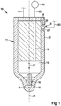
- the Indian Fig. 1 fuel injector 10 shown greatly simplified is designed as a so-called common rail injector, and is used to inject fuel into the combustion chamber, not shown, of an internal combustion engine, in particular a self-igniting internal combustion engine.
- the fuel injector 10 has an essentially made of metal, possibly multi-part design injector housing 11, in which on the combustion chamber of the internal combustion engine side facing at least one, preferably a plurality of injection openings 12 are arranged for injecting the fuel.
- this forms a high-pressure chamber 15, in which a nozzle needle 16 serving as an injection member is arranged in a liftable manner in the direction of the double arrow 17.
- a nozzle needle 16 serving as an injection member is arranged in a liftable manner in the direction of the double arrow 17.
- this forms together with the inner wall of the high-pressure chamber 15 and the injector 11 a sealing seat, so that the injection openings 12 are at least indirectly closed, such that the injection of fuel from the high-pressure chamber 15 in the Combustion chamber of the internal combustion engine is avoided.
- the nozzle needle 16 In the other, not shown, lifted from the sealing seat position of the nozzle needle 16, this releases the injection openings 12 for injecting the fuel into the combustion chamber of the internal combustion engine.
- the movement of the nozzle needle 16, in particular for releasing the injection openings 12, takes place in a manner known per se by means of an actuator, not shown, which can be actuated via a voltage supply line 18 by a control device of the internal combustion engine.
- the actuator may in particular be a magnetic actuator or else a piezoactuator.
- the supply bore 19 is also connected via a fuel connection, not shown, with a fuel line 22, which in turn is coupled to a fuel reservoir 25 (rail).
- axially relatively widely spaced portion of the injector 11 is in the outer wall 23 by way of example a blind hole-shaped recess 24 is formed, so that the wall thickness of the injector 11 is reduced in the region of the recess 24.
- the injector housing 11 can also have a flattening, in the region of which the wall thickness of the injector housing 11 is reduced.
- the newly formed base 26 of the recess 24 forms part of a deformation region 27.
- the fuel pressure currently prevailing in the supply bore 19 in the injector housing 11 also acts on the side remote from the recess 24. Due to the fact that the wall thickness of the injector housing 11 is reduced in the region of the depression 24, the wall of the injector housing 11 acts on the side of the deformation region 27 facing the recess 24 in the manner of an elastically deformable membrane, wherein the deformation, which develops as a convex curvature, the higher, the higher the instantaneous fuel pressure in the supply bore 19 is.
- the fuel injector 10 For detecting the instantaneous fuel pressure in the supply bore 19 and thus also in the high-pressure chamber 15, which is used as an indication of the instantaneous position of the nozzle needle 16 for driving the nozzle needle 16, the fuel injector 10 has a sensor device 30.
- the in the Fig. 2 in a single view in section shown sensor device 30 has two support elements 31, 32.
- the two support elements 31, 32 are partially arranged in abutting contact with each other and each have two oppositely disposed first portions 33, 34, two oppositely disposed second portions 35, 36 and a third portion 37, 38.
- the two first sections 33, 34 of the two carrier elements 31, 32 are arranged in abutting contact or in direct overlap with one another and each form a mounting region 39 for fastening the carrier elements 31, 32 to the injector housing 11 forming a carrier component.
- the two third sections 37, 38 are arranged offset parallel to the first two sections 33, 34, wherein in the unloaded state of the support members 31, 32 between the third sections 37, 38, a distance A is formed.
- the two second sections 35, 36 of the support elements 31, 32 extend in relation to the first sections 33, 34 each at an oblique angle ⁇ , wherein the angle ⁇ is more than 90 ° and less than 180 °, in the exemplary embodiment about 135 ° ,
- the two support elements 31, 32 or their sections 33 to 38 are formed symmetrically to a center plane 41 and to an axis of symmetry 42.
- the symmetry axis 42 cuts the supply bore 19 centrically.
- the second sections 35, 36 and the third sections 37, 38 of the support elements 31, 32 are arranged in the region of the recess 24, the first sections 33, 34 are each connected to the injector housing 11 in the region of the outer wall 23, for example by a laser weld 43. It is also essential that between the base 26 of the recess 24 and the base 26 facing first support member 31 in the region of the recess 24 no contact contact is formed or between the said elements, a gap 45 is formed.
- the two support elements 31, 32 which consist in particular of an elastically deformable material such as steel or aluminum, preferably form a closed housing 48 for receiving a device 50 for generating an electrical voltage.
- the device 50 has, in a region which coincides approximately with the median plane 41, a magnetic element 51 whose north pole N is arranged, for example, on the side facing the base 26, while its south pole S protrudes from the base 26.
- the magnetic element 51 is connected to the first carrier element 31 in the region of the third section 37 with the interposition of an intermediate element 52, which is of pin-shaped or cylindrical design by way of example.
- the magnetic element 51 is aligned in particular centric to the axis of symmetry 42.
- plastic coil receptacle 56 has a radially circumferential groove 57, in the region of the third portion 38 of the second support member 32 engages to hold the coil receptacle 56. Due to the spring force of the compression spring 55, the coil receptacle 56 is pushed away from the first support element 31.
- a magnetic coil 59 is disposed within a coil support 58, which also Part of the device 50 and which cooperates with the magnetic element 51. It is essential that the magnetic coil 59 is arranged in an unloaded state of the sensor device 30 in a plane below the median plane 41 and the magnetic element 51 on the base 26 side facing.
- the longitudinal axis of the magnet coil 59 coincides with the axis of symmetry 42 of the housing 48, such that the magnetic element 51 is surrounded concentrically by the magnet coil 59.
- the reduction of the distance A 'between the two support elements 31, 32 is accompanied by an increase in the angle a, which increases to an angle ⁇ '.
- Simultaneously with the reduction of the distance A ' is also a relative movement of the magnetic element 51 to the magnetic coil 59. This relative movement induces in the magnetic coil 59, an electrical voltage which via a in the Fig. 1 recognizable connecting line 63, for example, an evaluation circuit is supplied.
- the deformation region 27 of the injector housing 11 deforms elastically outward as a function of the fuel pressure prevailing in the supply bore 19. This deformation causes, as explained above, an increase in the distance between the two first portions 33, 34 of the support members 31, 32 in the region of the mounting portions 39.
- the voltage generated thereby by the device 50 can be used, at least indirectly to the position the nozzle needle 16 to close in the injector 11.
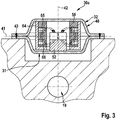
- the in the Fig. 3 The sensor device 30a shown differs from the sensor device 30 essentially in that the coil receptacle 64, which is completely accommodated between the two carrier elements 31, 32, is designed to receive two magnet coils 65, 66.
- the two axially spaced apart magnetic coils 65, 66 are wound in a different direction when using a single coil wire.
- the arrangement of the magnetic coils 65, 66 symmetrical to the center plane 41. Due to the different direction of the wire windings in the magnetic coils 65, 66 in a relative movement of the magnetic element 51 to the magnetic coils 65, 66 in each of these generates a voltage whose voltage signals are added can and thus produce a relative to the sensor device 30 increased voltage signal.
- the sensor devices 30, 30a described so far can be modified or modified in many ways without deviating from the inventive concept.
- the use of a sensor device 30, 30a described so far should not be limited to use in fuel injectors 10 or for detecting the position of the nozzle needle 16.
Description
- Die Erfindung betrifft eine Sensorvorrichtung zur Erfassung einer Bewegung eines Verformungsbereichs. Ferner betrifft die Erfindung einen Kraftstoffinjektor mit einer erfindungsgemäßen Sensorvorrichtung.
- Bei Kraftstoffinjektoren ist es zur Ansteuerung der als Einspritzglied dienenden Düsennadel sinnvoll bzw. erforderlich, den exakten Schließzeitpunkt bzw. Öffnungszeitpunkt des Einspritzglieds möglichst genau erfassen zu können. So ist beispielsweise aus der nachveröffentlichten
DE 10 2014 222 811 A1 und derDE 10 2014 209 324 A1 der Anmelderin bekannt, eine derartige Sensorvorrichtung unter Verwendung eines Piezoelements auszubilden. Bei dem bekannten Kraftstoffinjektor wird das Piezoelement unter Zwischenlage einer Klebstoffschicht an der Oberfläche eines Verformungsbereichs eines Injektorgehäuses des Kraftstoffinjektors befestigt. Mittels der Sensorvorrichtung lässt sich zumindest mittelbar der Druck in einer Versorgungsbohrung bzw. in einem Hochdruckraum des Kraftstoffinjektors ermitteln, woraus auf einen Schieß- bzw. Öffnungszeitpunkt des Einspritzglieds (Düsennadel) geschlossen werden kann. Die bekannte Sensorvorrichtung ist im Bereich einer Vertiefung des Injektorgehäuses angeordnet und mittels einer das Piezoelement an seiner der Klebstoffschicht gegenüberliegenden Stirnseite überdeckenden Einrichtung überdeckt. Die Einrichtung dient dazu, auf das Piezoelement eine axiale Vorspannkraft auszuüben, die zum einen die Zuverlässigkeit der Messeinrichtung bzw. des Piezoelements über die Lebensdauer des Kraftstoffinjektors gesehen erhöht, und zum anderen die Funktionalität des Piezoelements insofern verbessert, als dass auf das Piezoelement infolge der Deformation des Verformungsbereichs wirkende Zugspannungen reduziert werden. Hierzu ist die das Piezoelement teilweise überdeckende Einrichtung im Bereich der Vertiefung mit einer Schweißnaht mit dem Injektorgehäuse verbunden, um die benötigte axiale Vorspannkraft auf das Piezoelement zu erzeugen. Um einen Medienzutritt zu dem Piezoelement zu vermeiden, der die Funktionseigenschaften des Piezoelements, insbesondere über die Lebensdauer des Kraftstoffinjektors betrachtet, verschlechtern kann, ist es erforderlich, dass zwischen der Aufnahme bzw. der Vertiefung an dem Injektorgehäuse und der das Sensorelement teilweise überdeckenden Einrichtung eine vollständig umlaufende Schweißnaht ausgebildet ist, die den Bereich des Piezoelements abdichtet. Zusammengefasst ist die aus der genannten Schrift bekannte Sensorvorrichtung relativ komplex ausgebildet und es ist erforderlich, die Sensorvorrichtung zur Abdichtung sehr sorgfältig mit dem Injektorgehäuse zu verbinden. Darüber hinaus ist die Dauerhaltbarkeit von Klebstoffverbindungen über die Lebensdauer eines Kraftstoffinjektors betrachtet, welche typischerweise mit etwa 15 Jahren angenommen werden kann, insbesondere bei relativ ungünstigen Einsatzbedingungen als kritisch zu bewerten. - Aus der
DE 10 2014 204 746 A1 der Anmelderin ist es darüber hinaus bekannt, eine Sensorvorrichtung zur Erfassung einer Bewegung des Einspritzglieds, die ebenfalls im Bereich einer Vertiefung einer Hochdruckversorgungsbohrung angeordnet ist, ohne die Verwendung von Klebstoff auszubilden. Zwar findet auch bei dieser bekannten Sensorvorrichtung ein Piezoelement Verwendung, jedoch ist dieses mittels einer Spannvorrichtung gegen die Oberfläche einer Abflachung des Injektorgehäuses axial vorgespannt. Nachteilig dabei ist zum einen, dass durch die Spannvorrichtung die Baugröße des Kraftstoffinjektors in Höhe der Spannvorrichtung vergrößert wird, und dass zum anderen ohne die Verwendung geeigneter Schutzmaßnahmen ein Medienzutritt zu dem Piezoelement möglich ist, was dessen Lebensdauer ggf. beeinträchtigen kann. - Ausgehend von dem dargestellten Stand der Technik liegt der Erfindung die Aufgabe zugrunde, eine Sensorvorrichtung zur Erfassung einer Bewegung eines Verformungsbereichs derart auszubilden, dass auf die Verwendung eines Piezoelements sowie einer Klebeverbindung verzichtet werden kann, wobei gleichzeitig ein geschützter Anbau der Sensorvorrichtung ermöglicht werden soll, derart, dass der Zutritt von Medien zu dem Bereich der Sensorvorrichtung verhindert wird. Weiterhin soll es das verwendete Meßprinzip erlauben, zuverlässig, schnell und mit hoher Signalstärke die Bewegung des zu detektierenden Verformungsbereichs erfassen zu können.
- Diese Aufgabe wird erfindungsgemäß bei einer Sensorvorrichtung zur Erfassung der Bewegung eines Verformungsbereichs mit den Merkmalen des Anspruchs 1 gelöst.
- Die Erfindung nutzt dabei - im Gegensatz zum genannten Stand der Technik - eine wenigstens ein Spulenelement und ein Magnetelement aufweisende Einrichtung zur Erzeugung einer elektrischen Spannung, wobei das wenigstens eine Spulenelement und das Magnetelement auf unterschiedlichen Trägerelementen angeordnet bzw. befestigt sind. Wesentlich für die Idee der Erfindung ist es, dass die Trägerelemente derart elastisch verformbar sind, dass sich deren gegenseitiger Abstand in einem Bereich, in dem das Magnetelement bzw. das wenigstens eine Spulenelement angeordnet ist, derart verändert, dass die genannten Elemente aufeinander zubewegt bzw. voneinander wegbewegt werden. Wesentlich dabei ist auch, dass dies mit einer relativ hohen Geschwindigkeit bzw. Amplitude erfolgt, da beide Trägerelemente an der Bewegung in entgegengesetzter Richtung teilnehmen. Somit lässt sich in besonders vorteilhafter Art und Weise eine besonders schnelle Erfassung der Bewegung des Verformungsbereichs mit einer relativ hohen Spannungsamplitude bewerkstelligen.
- Vorteilhafte Weiterbildungen der erfindungsgemäßen Sensorvorrichtung sind in den Unteransprüchen aufgeführt.
- In besonders bevorzugter konstruktiver Ausgestaltung der Trägerelemente, die eine besonders einfache Anbindung bzw. Befestigung sowohl des wenigstens einen Spulenelements als auch des Magnetelements sowie eine Befestigung der Trägerelemente im Bereich des zu detektierenden Verformungsbereichs ermöglicht, wird vorgeschlagen, dass die beiden Trägerelemente in Bezug zur Längsachse des wenigstens einen Spulenelements in einem schrägen Winkel angeordnete Abschnitte aufweisen, die vorzugsweise zwischen senkrecht zur Längsachse verlaufenden Abschnitten im Bereich der Befestigungsbereiche der Trägerelemente für den Verformungsbereich und in einem mittleren Bereich der Trägerelemente, in dem das wenigstens eine Spulenelement und das Magnetelement angeordnet sind, verlaufen. Wesentlich dabei ist, dass durch die Größe der Winkel der schrägen Abschnitte und deren Ausrichtung die Bewegungsrichtung und Bewegungsgeschwindigkeit zwischen dem Magnetelement und dem wenigstens einen Spulenelement beeinflusst werden kann.
- Um bei der Bewegung der beiden Trägerelemente bzw. deren Verformung lediglich eine Bewegung des wenigstens einen Spulenelements sowie des Magnetelements in Richtung einer (gemeinsamen) Richtung bzw. Längsachse zu erzielen, jedoch nicht eine Querbewegung der genannten Elemente zueinander, ist es vorgesehen, dass die beiden Trägerelemente symmetrisch zu einer senkrecht zur Längsachse des wenigstens einen Spulenelements angeordneten Mittelebene und symmetrisch zur gemeinsamen Längsachse des wenigstens einen Spulenelements sowie des Magnetelements ausgebildet sind.
- Um insbesondere einen ausreichenden Schutz der Einrichtung zur Erzeugung der elektrischen Spannung über eine längere Lebensdauer der Einrichtung zu erzielen und darüber hinaus den Zutritt von Medien, die die Funktionalität der Einrichtung zur Erzeugung der elektrischen Spannung beeinträchtigen, zu verhindern, ist es vorgesehen, dass die beiden Trägerelemente ein geschlossenes Gehäuse zur Aufnahme des Magnetelements und des wenigstens einen Spulenelements ausbilden.
- Ein besonders kompakter Aufbau der Einrichtung zur Erzeugung der elektrischen Spannung lässt sich darüber hinaus erzielen, wenn das Magnetelement konzentrisch von dem wenigstens einen Spulenelement umgeben ist. Dadurch ist die Baugröße bzw. der Durchmesser der Einrichtung (lediglich) von der Baugröße des wenigstens einen Spulenelements bestimmt.
- In einer konstruktiv bevorzugten Gestaltung, die hinsichtlich der Herstellungskosten besonders günstig realisierbar ist, ist es vorgesehen, dass ein einziges Spulenelement vorgesehen ist, und dass das Magnetelement in Bezug zur Längsachse des Spulenelements in einer Ebene außerhalb des Spulenelements angeordnet ist. Eine derartige Anordnung bewirkt bei einer Relativbewegung des Magnetelements zu dem Spulenelement zueinander eine relativ große Änderung der magnetischen Feldlinien des Magnetelements bzw. deren Richtung im Bereich des Spulenelements, so dass das in dem Spulenelement induzierte Spannungssignal sich besonders einfach auswerten lässt.
- In alternativer Ausgestaltung, welche insbesondere besonders große Spannungssignale erzeugt, ist es vorgesehen, dass zwei Spulenelemente, dass die beiden Spulenelemente in Bezug zu einer gemeinsamen Längsachse axial voneinander beabstandet angeordnet sind, und dass das Magnetelement in einer Ebene zwischen den beiden Spulenelementen angeordnet ist. Eine derartige Anordnung des Magnetelements zwischen den beiden Spulenelementen bewirkt insbesondere, dass bei einer Relativbewegung des Magnetelements zu den beiden Spulenelementen in den beiden Spulenelementen jeweils Spannungen induziert werden, die sich gegenseitig addieren. Um die Addition der Spannungs signale bei Verwendung eines einzigen Spulendrahts für die beiden Spulenelemente zu ermöglichen, muss die Wicklungsrichtung an den beiden Spulenelementen unterschiedlich sein.
- Die Erfindung umfasst auch einen Kraftstoffinjektor mit einer soweit beschriebenen erfindungsgemäßen Sensorvorrichtung, wobei die Sensorvorrichtung dazu ausgebildet ist, die Position eines Einspritzglieds bzw. einer Düsen nadel des Kraftstoffinjektors zumindest mittelbar zu erfassen. Eine derartige Erfassung dient in bevorzugter Art und Weise der Ansteuerung des Kraftstoffinjektors zur zeitgerechten Bewegung des Einspritzglieds.
- In konstruktiv bevorzugter Anordnung einer derartigen Sensorvorrichtung an einem Kraftsloffinjektor ist es vorgesehen, dass die Sensorvorrichtung im Bereich einer Kraftstoffversorgungsbohrung an der Oberfläche eines Injektorgehäuses angeordnet ist, dass die Wandstärke des Injektorgehäuses im Bereich der Sensorvorrichtung bereichsweise reduziert ist, und dass die beiden Befestigungs bereiche der Trägerelemente außerhalb des in der Wandstärke reduzierten Bereichs angeordnet und mit dem Injektorgehäuse starr verbunden sind. Somit bildet der in der Wandstärke reduzierte Bereich des Injektorgehäuses den zu detektierenden Verformungsbereich aus.
- Bei der soweit beschriebenen erfindungsgemäßen Sensorvorrichtung unter Verwendung zweier Trägerelemente ist es darüber hinaus von Vorteil, wenn die beiden Trägerelemente in dem in der Wandstärke des Injektorgehäuses reduzierten Bereich ohne Kontakt zum Injektorgehäuse angeordnet sind. Dadurch ist insbesondere keine Berührung bzw. kein Kontakt zwischen dem Injektorgehäuse und den Trägerelementen in dem Bereich möglich, in denen das Magnetelement bzw. das wenigstens eine Spulenelement angeordnet sind.
- Weitere Vorteile, Merkmale und Einzelheiten der Erfindung ergeben sich aus der nachfolgenden Beschreibung bevorzugter Ausführungsbeispiele sowie anhand der Zeichnung.
-
- Fig. 1
- eine stark vereinfachte, teilweise geschnittene Seitenansicht eines erfindungsgemäßen Kraftstoffinjektors mit einer Sensorvorrichtung zur zumindest mittelbaren Erfassung des Kraftstoffdrucks im Kraftstoffinjektor,
- Fig. 2
- eine erste Ausführungsform einer erfindungsgemäßen Sensorvorrichtung unter Verwendung eines einzigen Spulenelements in einer Schnittdarstellung,
- Fig. 3
- eine gegenüber
Fig. 2 modifizierte Sensorvorrichtung unter Verwendung zweier, axial voneinander beabstandet angeordneter Spulenelemente, ebenfalls in einer Schnittdarstellung und - Fig. 4
- die beiden Trägerelemente, die bei der Sensorvorrichtung gemäß der
Fig. 2 und3 verwendet werden, in einer Einzeldarstellung in einem unverformten und in einem verformten Zustand. - Der in der
Fig. 1 stark vereinfacht dargestellte Kraftstoffinjektor 10 ist als sogenannter Common-Rail-Injektor ausgebildet, und dient dem Einspritzen von Kraftstoff in den nicht gezeigten Brennraum einer Brennkraftmaschine, insbesondere einer selbstzündenden Brennkraftmaschine. - Der Kraftstoffinjektor 10 weist ein im Wesentlichen aus Metall bestehendes, ggf. mehrteilig ausgebildetes Injektorgehäuse 11 auf, in dem auf der dem Brennraum der Brennkraftmaschine zugewandten Seite wenigstens eine, vorzugsweise mehrere Einspritzöffnungen 12 zum Einspritzen des Kraftstoffs eingeordnet sind. Innerhalb des Injektorgehäuses 11 bildet dieses einen Hochdruckraum 15 aus, in dem eine als Einspritzglied dienende Düsennadel 16 in Richtung des Doppelpfeils 17 hubbeweglich angeordnet ist. In der dargestellten, abgesenkten Stellung der Düsennadel 16 bildet diese zusammen mit der Innenwand des Hochdruckraums 15 bzw. des Injektorgehäuses 11 einen Dichtsitz aus, so dass die Einspritzöffnungen 12 zumindest mittelbar verschlossen sind, derart, dass das Einspritzen von Kraftstoff aus dem Hochdruckraum 15 in den Brennraum der Brennkraftmaschine vermieden wird. In der anderen, nicht dargestellten, von dem Dichtsitz abgehobenen Position der Düsennadel 16 gibt diese die Einspritzöffnungen 12 zum Einspritzen des Kraftstoffs in den Brennraum der Brennkraftmaschine frei. Die Bewegung der Düsennadel 16, insbesondere zum Freigeben der Einspritzöffnungen 12, erfolgt auf eine an sich bekannte Art und Weise mittels eines nicht dargestellten Aktuators, der über eine Spannungsversorgungsleitung 18 von einer Steuereinrichtung der Brennkraftmaschine ansteuerbar ist. Bei dem Aktuator kann es sich insbesondere um einen Magnetaktuator oder aber um einen Piezoaktuator handeln.
- Die Versorgung des Hochdruckraums 15 mit unter Hochdruck (Systemdruck) stehendem Kraftstoff erfolgt über eine innerhalb des Injektorgehäuses 11 angeordnete bzw. in Bauteilen des Kraftstoffinjektors 10 ausgebildete Versorgungsbohrung 19, die insbesondere exzentrisch zur Längsachse 21 des Injektorgehäuses 11 in einem Randbereich des Kraftstoffinjektors 10, zumindest im Wesentlichen parallel zur Längsachse 21, verläuft. Die Versorgungsbohrung 19 ist darüber hinaus über einen nicht dargestellten Kraftstoffanschlussstutzen mit einer Kraftstoffleitung 22 verbunden, welche wiederum mit einem Kraftstoffspeicher 25 (Rail) gekoppelt ist.
- In einem von den Einspritzöffnungen 12 axial relativ weit beabstandeten Bereich des Injektorgehäuses 11 ist in dessen Außenwand 23 beispielhaft eine sacklochförmige Vertiefung 24 ausgebildet, so dass die Wanddicke des Injektorgehäuses 11 im Bereich der Vertiefung 24 reduziert ist. Ergänzend wird erwähnt, dass anstelle einer sacklochförmigen Vertiefung 24 das Injektorgehäuse 11 auch eine Abflachung aufweisen kann, in deren Bereich die Wanddicke des Injektorgehäuses 11 reduziert ist.
- Der eben ausgebildete Grund 26 der Vertiefung 24 bildet einen Teil eines Verformungsbereichs 27 aus. Dadurch wirkt der in der Versorgungsbohrung 19 augenblicklich herrschende Kraftstoffdruck in dem Injektorgehäuse 11 auch auf der der Vertiefung 24 abgewandten Seite. Dadurch, dass die Wanddicke des Injektorgehäuses 11 im Bereich der Vertiefung 24 reduziert ist, wirkt die Wand des Injektorgehäuses 11 auf der der Vertiefung 24 zugewandten Seite des Verformungsbereichs 27 in Art einer elastisch verformbaren Membran, wobei die Verformung, welche sich als konvexe Wölbung ausbildet, umso größer ist, je höher der augenblickliche Kraftstoffdruck in der Versorgungsbohrung 19 ist.
- Zur Detektion des augenblicklichen Kraftstoffdrucks in der Versorgungsbohrung 19 und damit auch in dem Hochdruckraum 15, welcher als Indiz für die augenblickliche Stellung der Düsennadel 16 zur Ansteuerung der Düsennadel 16 verwendet wird, weist der Kraftstoffinjektor 10 eine Sensorvorrichtung 30 auf.
- Die in der
Fig. 2 in Einzeldarstellung im Schnitt gezeigte Sensorvorrichtung 30 weist zwei Trägerelemente 31, 32 auf. Die beiden Trägerelemente 31, 32 sind bereichsweise in Anlagekontakt zueinander angeordnet und weisen jeweils zwei gegenüberliegend angeordnete erste Abschnitte 33, 34, zwei gegenüberliegend angeordnete zweite Abschnitte 35, 36 sowie einen dritten Abschnitt 37, 38 auf. Die beiden ersten Abschnitte 33, 34 der beiden Trägerelemente 31, 32 sind in Anlagekontakt bzw. in unmittelbarer Überdeckung zueinander angeordnet und bilden jeweils einen Befestigungsbereich 39 zur Befestigung der Trägerelemente 31, 32 an dem ein Trägerbauteil ausbildenden Injektorgehäuse 11 aus. Die beiden dritten Abschnitte 37, 38 sind parallel versetzt zu den beiden ersten Abschnitten 33, 34 angeordnet, wobei im unbelasteten Zustand der Trägerelemente 31, 32 zwischen den dritten Abschnitten 37, 38 ein Abstand A ausgebildet ist. Die beiden zweiten Abschnitte 35, 36 der Trägerelemente 31, 32 verlaufen in Bezug zu den ersten Abschnitten 33, 34 jeweils in einem schrägen Winkel α, wobei der Winkel α mehr als 90° und weniger als 180°, im Ausführungsbeispiel etwa 135°, beträgt. - Die beiden Trägerelemente 31, 32 bzw. deren Abschnitte 33 bis 38 sind symmetrisch zu einer Mittelebene 41 sowie zu einer Symmetrieachse 42 ausgebildet. Insbesondere schneidet die Symmetrieachse 42 die Versorgungsbohrung 19 zentrisch. Während die zweiten Abschnitte 35, 36 und die dritten Abschnitte 37, 38 der Trägerelemente 31, 32 im Bereich der Vertiefung 24 angeordnet sind, sind die ersten Abschnitte 33, 34 jeweils mit dem Injektorgehäuse 11 im Bereich der Außenwand 23 verbunden, beispielsweise durch eine Laserschweißnaht 43. Wesentlich ist auch, dass zwischen dem Grund 26 der Vertiefung 24 und dem dem Grund 26 zugewandten ersten Trägerelement 31 im Bereich der Vertiefung 24 kein Anlagekontakt ausgebildet ist bzw. zwischen den genannten Elementen ein Spalt 45 ausgebildet ist.
- Die beiden Trägerelemente 31, 32, welche insbesondere aus einem elastisch verformbaren Material wie Stahl oder Aluminium bestehen, bilden vorzugsweise ein geschlossenes Gehäuse 48 zur Aufnahme einer Einrichtung 50 zur Erzeugung einer elektrischen Spannung aus. Die Einrichtung 50 weist in einem Bereich, der in etwa mit der Mittelebene 41 zusammenfällt, ein Magnetelement 51 auf, dessen Nordpol N beispielhaft auf der dem Grund 26 zugewandten Seite angeordnet ist, während dessen Südpol S von dem Grund 26 wegragt. Das Magnetelement 51 ist unter Zwischenlage eines beispielhaft stiftförmig bzw. zylindrisch ausgebildeten Zwischenelements 52 mit dem ersten Trägerelement 31 im Bereich des dritten Abschnitts 37 verbunden. Hierbei ist das Magnetelement 51 insbesondere zentrisch zur Symmetrieachse 42 ausgerichtet. Auf der dem Zwischenelement 52 abgewandten Seite des Magnetelements 51 stützt sich unter Zwischenlage eines weiteren Elements 53 eine Druckfeder 55 ab, deren Federkraft sich auf der dem Element 53 abgewandten Seite am Grund einer topfartigen Spulenaufnahme 56 abstützt.
- Die beispielsweise aus Kunststoff bestehende Spulenaufnahme 56 weist eine radial umlaufende Nut 57 auf, in deren Bereich der dritte Abschnitt 38 des zweiten Trägerelements 32 eingreift, um die Spulenaufnahme 56 zu halten. Durch die Federkraft der Druckfeder 55 wird die Spulenaufnahme 56 von dem ersten Trägerelement 31 weggedrückt.
- Auf der dem Grund 26 zugewandten Seite der Spulenaufnahme 56 ist innerhalb eines Spulenträgers 58 eine Magnetspule 59 angeordnet, die ebenfalls Bestandteil der Einrichtung 50 ist und die mit dem Magnetelement 51 zusammenwirkt. Wesentlich dabei ist, dass die Magnetspule 59 in einem unbelasteten Zustand der Sensorvorrichtung 30 in einer Ebene unterhalb der Mittelebene 41 bzw. des Magnetelements 51 auf der dem Grund 26 zugewandten Seite angeordnet ist. Die Längsachse der Magnetspule 59 fällt mit der Symmetrieachse 42 des Gehäuses 48 zusammen, derart, dass das Magnetelement 51 von der Magnetspule 59 konzentrisch umgeben ist.
- Mit Bezug auf die
Fig. 4 wird erläutert, dass sich der Abstand A zwischen den beiden dritten Abschnitten 37, 38 der beiden Trägerelemente 31, 32 aus dem in derFig. 2 dargestellten Zustand auf ein Maß A' (gestrichelte Darstellung in derFig. 4 ) verringert, wenn die beiden Trägerelemente 31, 32 in Richtung der in derFig. 4 dargestellten Pfeile 61, 62 voneinander wegbewegt werden. Eine derartige Bewegung der Trägerelemente 31, 32 im Bereich der ersten Abschnitte 33, 34 findet dann statt, wenn aufgrund einer (elastischen) Deformation des Verformungsbereichs 27 eine Deformation des Injektorgehäuses 11 an deren Befestigungsbereichen 39 am Injektorgehäuse 11 erfolgt, welche dazu führt, dass die beiden Trägerelemente 31, 32 im Bereich der Befestigungsbereiche 39 zu der Außenwand 23 des Injektorgehäuses 11 voneinander wegbewegt werden. Die Verringerung des Abstandes A' zwischen den beiden Trägerelementen 31, 32 geht einher mit einer Vergrößerung des Winkels a, welcher sich auf einen Winkel α' vergrößert. Gleichzeitig einher mit der Verringerung des Abstands A' geht auch eine Relativbewegung des Magnetelements 51 zu der Magnetspule 59. Diese Relativbewegung induziert in der Magnetspule 59 eine elektrische Spannung, welche über eine in derFig. 1 erkennbare Anschlussleitung 63 beispielsweise einer Auswerteschaltung zugeführt wird. - Beim Betrieb des Kraftstoffinjektors 10 verformt sich der Verformungsbereich 27 des Injektorgehäuses 11 in Abhängigkeit des in der Versorgungsbohrung 19 herrschenden Kraftstoffdrucks elastisch nach außen. Diese Verformung bewirkt, wie oben erläutert, eine Vergrößerung des Abstandes zwischen den beiden ersten Abschnitten 33, 34 der Trägerelemente 31, 32 im Bereich der Befestigungsbereiche 39. Die dadurch von der Einrichtung 50 erzeugte elektrische Spannung kann dazu verwendet werden, zumindest mittelbar auf die Stellung der Düsennadel 16 in den Injektorgehäuse 11 zu schließen.
- Die in der
Fig. 3 gezeigte Sensorvorrichtung 30a unterscheidet sich von der Sensorvorrichtung 30 im Wesentlichen dadurch, dass die Spulenaufnahme 64, die vollständig zwischen den beiden Trägerelementen 31, 32 aufgenommen ist, dazu ausgebildet ist, zwei Magnetspulen 65, 66 aufzunehmen. Die beiden axial voneinander beabstandeten Magnetspulen 65, 66 sind bei Verwendung eines einzigen Spulendrahtes in unterschiedlicher Richtung bewickelt. Weiterhin ist die Anordnung der Magnetspulen 65, 66 symmetrisch zur Mittelebene 41. Durch die unterschiedliche Richtung der Drahtwicklungen in den Magnetspulen 65, 66 wird bei einer Relativbewegung des Magnetelements 51 zu den Magnetspulen 65, 66 in diesen jeweils eine Spannung erzeugt, deren Spannungssignale addiert werden können und somit ein gegenüber der Sensorvorrichtung 30 erhöhtes Spannungssignal erzeugen. - Die soweit beschriebenen Sensorvorrichtungen 30, 30a können in vielfältiger Art und Weise abgewandelt bzw. modifiziert werden, ohne vom Erfindungsgedanken abzuweichen. Insbesondere wird auch darauf hingewiesen, dass der Einsatz einer soweit beschriebenen Sensorvorrichtung 30, 30a nicht auf die Verwendung in Kraftstoffinjektoren 10 bzw. zur Detektion der Stellung der Düsennadel 16 beschränkt sein soll.
Claims (10)
- Sensorvorrichtung (30; 30a) zur Erfassung der Bewegung eines Verformungsbereichs (27), mit einer Einrichtung (50) zur Erzeugung einer elektrischen Spannung, wobei die Einrichtung (50) zumindest ein Magnetelement (51) und wenigstens ein relativ zum Magnetelement (51) beweglich angeordnetes, mit dem Magnetelement (51) zusammenwirkendes Spulenelement (59; 65, 66) aufweist, wobei das Magnetelement (51) an einem ersten Trägerelement (31) und das wenigstens eine Spulenelement (59; 65, 66) an einem zweiten Trägerelement (32) befestigt ist, wobei die beiden Trägerelemente (31; 32) ein Gehäuse zur Aufnahme der Einrichtung (50) bilden und die beiden Trägerelemente (31, 32) in Bezug zu einer senkrecht zu einer Längsachse (42) des wenigstens einen Spulenelements (59; 65, 66) verlaufenden Richtung auf gegenüberliegenden Seiten des wenigstens einen Spulenelements (59; 65, 66) jeweils einen Befestigungsbereich (39) zur Befestigung an einem Injektorgehäuse (11) aufweisen, welches Injektorgehäuse (11) den Verformungsbereich (27) ausbildet, wobei die beiden Trägerelemente (31, 32) in einem Bereich zwischen den Befestigungsbereichen (39) elastisch verformbar sind, und wobei sich bei der Verformung der Trägerelemente (31, 32) die Position zwischen dem Magnetelement (51) und dem wenigstens einen Spulenelement (59; 65, 66) ändert.
- Sensorvorrichtung nach Anspruch 1,
dadurch gekennzeichnet,
dass die beiden Trägerelemente (31, 32) in Bezug zur Längsachse (42) des wenigstens eine Spulenelements (59; 65, 66) in einem schrägen Winkel (α) angeordnete Abschnitte (35, 36) aufweisen, die vorzugsweise zwischen senkrecht zur Längsachse (42) verlaufenden Abschnitten (33, 34, 37, 38) im Bereich der Befestigungsbereiche (39) und einem mittleren Bereich der Trägerelemente (31, 32), in dem das wenigstens eine Spulenelement (59; 65, 66) und das Magnetelement (51) angeordnet sind, verlaufen. - Sensorvorrichtung nach Anspruch 2,
dadurch gekennzeichnet,
dass die beiden Trägerelemente (31, 32) symmetrisch zu einer senkrecht zur Längsachse (42) des wenigstens einen Spulenelements (59; 65, 66) angeordneten Mittelebene (41) und symmetrisch zur Längsachse (42) ausgebildet sind - Sensorvorrichtung nach einem der Ansprüche 1 bis 3,
dadurch gekennzeichnet,
dass die beiden Trägerelemente (31, 32) ein geschlossenes Gehäuse (48) zur Aufnahme des Magnetelements (51) und des wenigstens einen Spulenelements (59; 65, 66) ausbilden. - Sensorvorrichtung nach einem der Ansprüche 1 bis 4,
dadurch gekennzeichnet,
dass das Magnetelement (51) konzentrisch zu dem wenigstens einen Spulenelement (59; 65, 66) angeordnet ist. - Sensorvorrichtung nach einem der Ansprüche 1 bis 5,
dadurch gekennzeichnet,
dass ein einziges Spulenelement (59) vorgesehen ist, und dass das Magnetelement (51) in Bezug zu einer senkrecht zur Längsachse (42) des Spulenelements (59) verlaufenden Richtung in einer Ebene außerhalb des Spulenelements (59) angeordnet ist. - Sensorvorrichtung nach einem der Ansprüche 1 bis 5,
dadurch gekennzeichnet,
dass zwei Spulenelemente (65, 66) vorgesehen sind, dass die beiden Spulenelemente (65, 66) in Bezug zu einer gemeinsamen Längsachse (42) axial voneinander beabstandet angeordnet sind, und dass das Magnetelement (51) in einer Ebene zwischen den beiden Spulenelementen (65, 66) angeordnet ist. - Kraftstoffinjektor (10) mit einer Sensorvorrichtung (30; 30a) nach einem der Ansprüche 1 bis 7.
- Kraftstoffinjektor nach Anspruch 8,
dadurch gekennzeichnet,
dass die Sensorvorrichtung (30; 30a) im Bereich einer Kraftstoffversorgungsbohrung (19) an einer Oberfläche (23) des Injektorgehäuses (11) angeordnet ist, dass die Wandstärke des Injektorgehäuses (11) im Bereich der Sensorvorrichtung (30; 30a) bereichsweise reduziert ist und dadurch den zu detektierenden Verformungsbereich (27) ausbildet, und dass die beiden Befestigungsbereiche (39) außerhalb des in der Wandstärke reduzierten Bereichs angeordnet und mit dem Injektorgehäuse (11) starr verbunden sind. - Kraftstoffinjektor nach Anspruch 9,
dadurch gekennzeichnet,
dass die beiden Trägerelemente (31, 32) in dem in der Wandstärke des Injektorgehäuses (11) reduzierten Bereich ohne Kontakt zum Injektorgehäuse (11) angeordnet sind.
Applications Claiming Priority (1)
| Application Number | Priority Date | Filing Date | Title |
|---|---|---|---|
| DE102015223902.0A DE102015223902A1 (de) | 2015-12-01 | 2015-12-01 | Sensorvorrichtung und Kraftstoffinjektor mit einer Sensorvorrichtung |
Publications (2)
| Publication Number | Publication Date |
|---|---|
| EP3176556A1 EP3176556A1 (de) | 2017-06-07 |
| EP3176556B1 true EP3176556B1 (de) | 2018-06-06 |
Family
ID=57421703
Family Applications (1)
| Application Number | Title | Priority Date | Filing Date |
|---|---|---|---|
| EP16200914.6A Not-in-force EP3176556B1 (de) | 2015-12-01 | 2016-11-28 | Sensorvorrichtung und kraftstoffinjektor mit einer sensorvorrichtung |
Country Status (2)
| Country | Link |
|---|---|
| EP (1) | EP3176556B1 (de) |
| DE (1) | DE102015223902A1 (de) |
Family Cites Families (7)
| Publication number | Priority date | Publication date | Assignee | Title |
|---|---|---|---|---|
| DE19813756A1 (de) * | 1998-03-27 | 1999-10-07 | Siemens Ag | Messung des Drucks eines Fluids |
| JP2001170393A (ja) * | 1999-12-16 | 2001-06-26 | Techno Excel Co Ltd | 圧力センサ |
| KR20030009848A (ko) * | 2001-07-24 | 2003-02-05 | 주식회사 엘지이아이 | 세탁기용 수위감지장치 |
| ITTO20050027U1 (it) * | 2005-02-18 | 2006-08-19 | Elbi Int Spa | Sensore induttivo di pressione, particolarmente per elettrodomestici, caldaie e simili |
| DE102014204746A1 (de) | 2014-03-14 | 2015-09-17 | Robert Bosch Gmbh | Kraftstoffinjektor, insbesondere Common-Rail-Injektor |
| DE102014209324A1 (de) * | 2014-05-16 | 2015-11-19 | Robert Bosch Gmbh | Kraftstoffinjektor, insbesondere Common-Rail-Injektor |
| DE102014222811A1 (de) | 2014-11-07 | 2016-05-12 | Robert Bosch Gmbh | Kraftstoffinjektor |
-
2015
- 2015-12-01 DE DE102015223902.0A patent/DE102015223902A1/de not_active Withdrawn
-
2016
- 2016-11-28 EP EP16200914.6A patent/EP3176556B1/de not_active Not-in-force
Non-Patent Citations (1)
| Title |
|---|
| None * |
Also Published As
| Publication number | Publication date |
|---|---|
| DE102015223902A1 (de) | 2017-06-01 |
| EP3176556A1 (de) | 2017-06-07 |
Similar Documents
| Publication | Publication Date | Title |
|---|---|---|
| EP3018337B1 (de) | Kraftstoffinjektor | |
| EP3076002B1 (de) | Kraftstoffinjektor | |
| EP3088729B1 (de) | Kraftstoffinjektor sowie vorrichtung und verfahren zur montage einer messeinrichtung | |
| EP3176556B1 (de) | Sensorvorrichtung und kraftstoffinjektor mit einer sensorvorrichtung | |
| EP3179090B1 (de) | Kraftstoffinjektor | |
| EP3111079B1 (de) | Kraftstoffinjektor | |
| DE102015211186A1 (de) | Kraftstoffinjektor | |
| EP3018336B1 (de) | Kraftstoffinjektor | |
| EP3088723B1 (de) | Kraftstoffinjektor | |
| EP3023758B1 (de) | Kraftstoffinjektor | |
| EP3076005B1 (de) | Kraftstoffinjektor und verfahren zum herstellen eines kraftstoffinjektors | |
| DE102015208488A1 (de) | Kraftstoffinjektor sowie Vorrichtung und Verfahren zur Montage einer Messeinrichtung | |
| EP3034854B1 (de) | Kraftstoffinjektor und verfahren zur erkennung zumindest des schliesszeitpunkts eines einspritzglieds | |
| DE102018208318A1 (de) | Kraftstoffinjektor | |
| EP3109453A1 (de) | Kraftstoffinjektor | |
| EP3908743B1 (de) | Kraftstoffinjektor | |
| EP3181890A1 (de) | Sensorvorrichtung und kraftstoffinjektor mit einer sensorvorrichtung | |
| EP3159533B1 (de) | Kraftstoffinjektor | |
| EP3056724A1 (de) | Kraftstoffinjektor und verfahren zur herstellung eines piezoelements für einen kraftstoffinjektor | |
| EP3026253B1 (de) | Kraftstoffinjektor | |
| EP3112662A1 (de) | Kraftstoffinjektor | |
| EP3088724A1 (de) | Kraftstoffinjektor | |
| EP3023627A1 (de) | Kraftstoffinjektor |
Legal Events
| Date | Code | Title | Description |
|---|---|---|---|
| AK | Designated contracting states |
Kind code of ref document: A1 Designated state(s): AL AT BE BG CH CY CZ DE DK EE ES FI FR GB GR HR HU IE IS IT LI LT LU LV MC MK MT NL NO PL PT RO RS SE SI SK SM TR |
|
| AX | Request for extension of the european patent |
Extension state: BA ME |
|
| PUAI | Public reference made under article 153(3) epc to a published international application that has entered the european phase |
Free format text: ORIGINAL CODE: 0009012 |
|
| 17P | Request for examination filed |
Effective date: 20171207 |
|
| RBV | Designated contracting states (corrected) |
Designated state(s): AL AT BE BG CH CY CZ DE DK EE ES FI FR GB GR HR HU IE IS IT LI LT LU LV MC MK MT NL NO PL PT RO RS SE SI SK SM TR |
|
| GRAP | Despatch of communication of intention to grant a patent |
Free format text: ORIGINAL CODE: EPIDOSNIGR1 |
|
| INTG | Intention to grant announced |
Effective date: 20180222 |
|
| GRAS | Grant fee paid |
Free format text: ORIGINAL CODE: EPIDOSNIGR3 |
|
| GRAA | (expected) grant |
Free format text: ORIGINAL CODE: 0009210 |
|
| AK | Designated contracting states |
Kind code of ref document: B1 Designated state(s): AL AT BE BG CH CY CZ DE DK EE ES FI FR GB GR HR HU IE IS IT LI LT LU LV MC MK MT NL NO PL PT RO RS SE SI SK SM TR |
|
| REG | Reference to a national code |
Ref country code: GB Ref legal event code: FG4D Free format text: NOT ENGLISH |
|
| REG | Reference to a national code |
Ref country code: CH Ref legal event code: EP Ref country code: AT Ref legal event code: REF Ref document number: 1006641 Country of ref document: AT Kind code of ref document: T Effective date: 20180615 |
|
| REG | Reference to a national code |
Ref country code: IE Ref legal event code: FG4D Free format text: LANGUAGE OF EP DOCUMENT: GERMAN |
|
| REG | Reference to a national code |
Ref country code: DE Ref legal event code: R096 Ref document number: 502016001172 Country of ref document: DE |
|
| REG | Reference to a national code |
Ref country code: NL Ref legal event code: MP Effective date: 20180606 |
|
| REG | Reference to a national code |
Ref country code: LT Ref legal event code: MG4D |
|
| PG25 | Lapsed in a contracting state [announced via postgrant information from national office to epo] |
Ref country code: BG Free format text: LAPSE BECAUSE OF FAILURE TO SUBMIT A TRANSLATION OF THE DESCRIPTION OR TO PAY THE FEE WITHIN THE PRESCRIBED TIME-LIMIT Effective date: 20180906 Ref country code: SE Free format text: LAPSE BECAUSE OF FAILURE TO SUBMIT A TRANSLATION OF THE DESCRIPTION OR TO PAY THE FEE WITHIN THE PRESCRIBED TIME-LIMIT Effective date: 20180606 Ref country code: FI Free format text: LAPSE BECAUSE OF FAILURE TO SUBMIT A TRANSLATION OF THE DESCRIPTION OR TO PAY THE FEE WITHIN THE PRESCRIBED TIME-LIMIT Effective date: 20180606 Ref country code: ES Free format text: LAPSE BECAUSE OF FAILURE TO SUBMIT A TRANSLATION OF THE DESCRIPTION OR TO PAY THE FEE WITHIN THE PRESCRIBED TIME-LIMIT Effective date: 20180606 Ref country code: LT Free format text: LAPSE BECAUSE OF FAILURE TO SUBMIT A TRANSLATION OF THE DESCRIPTION OR TO PAY THE FEE WITHIN THE PRESCRIBED TIME-LIMIT Effective date: 20180606 Ref country code: CY Free format text: LAPSE BECAUSE OF FAILURE TO SUBMIT A TRANSLATION OF THE DESCRIPTION OR TO PAY THE FEE WITHIN THE PRESCRIBED TIME-LIMIT Effective date: 20180606 Ref country code: NO Free format text: LAPSE BECAUSE OF FAILURE TO SUBMIT A TRANSLATION OF THE DESCRIPTION OR TO PAY THE FEE WITHIN THE PRESCRIBED TIME-LIMIT Effective date: 20180906 |
|
| PG25 | Lapsed in a contracting state [announced via postgrant information from national office to epo] |
Ref country code: LV Free format text: LAPSE BECAUSE OF FAILURE TO SUBMIT A TRANSLATION OF THE DESCRIPTION OR TO PAY THE FEE WITHIN THE PRESCRIBED TIME-LIMIT Effective date: 20180606 Ref country code: RS Free format text: LAPSE BECAUSE OF FAILURE TO SUBMIT A TRANSLATION OF THE DESCRIPTION OR TO PAY THE FEE WITHIN THE PRESCRIBED TIME-LIMIT Effective date: 20180606 Ref country code: HR Free format text: LAPSE BECAUSE OF FAILURE TO SUBMIT A TRANSLATION OF THE DESCRIPTION OR TO PAY THE FEE WITHIN THE PRESCRIBED TIME-LIMIT Effective date: 20180606 Ref country code: GR Free format text: LAPSE BECAUSE OF FAILURE TO SUBMIT A TRANSLATION OF THE DESCRIPTION OR TO PAY THE FEE WITHIN THE PRESCRIBED TIME-LIMIT Effective date: 20180907 |
|
| PG25 | Lapsed in a contracting state [announced via postgrant information from national office to epo] |
Ref country code: NL Free format text: LAPSE BECAUSE OF FAILURE TO SUBMIT A TRANSLATION OF THE DESCRIPTION OR TO PAY THE FEE WITHIN THE PRESCRIBED TIME-LIMIT Effective date: 20180606 |
|
| PG25 | Lapsed in a contracting state [announced via postgrant information from national office to epo] |
Ref country code: CZ Free format text: LAPSE BECAUSE OF FAILURE TO SUBMIT A TRANSLATION OF THE DESCRIPTION OR TO PAY THE FEE WITHIN THE PRESCRIBED TIME-LIMIT Effective date: 20180606 Ref country code: IS Free format text: LAPSE BECAUSE OF FAILURE TO SUBMIT A TRANSLATION OF THE DESCRIPTION OR TO PAY THE FEE WITHIN THE PRESCRIBED TIME-LIMIT Effective date: 20181006 Ref country code: PL Free format text: LAPSE BECAUSE OF FAILURE TO SUBMIT A TRANSLATION OF THE DESCRIPTION OR TO PAY THE FEE WITHIN THE PRESCRIBED TIME-LIMIT Effective date: 20180606 Ref country code: EE Free format text: LAPSE BECAUSE OF FAILURE TO SUBMIT A TRANSLATION OF THE DESCRIPTION OR TO PAY THE FEE WITHIN THE PRESCRIBED TIME-LIMIT Effective date: 20180606 Ref country code: SK Free format text: LAPSE BECAUSE OF FAILURE TO SUBMIT A TRANSLATION OF THE DESCRIPTION OR TO PAY THE FEE WITHIN THE PRESCRIBED TIME-LIMIT Effective date: 20180606 Ref country code: RO Free format text: LAPSE BECAUSE OF FAILURE TO SUBMIT A TRANSLATION OF THE DESCRIPTION OR TO PAY THE FEE WITHIN THE PRESCRIBED TIME-LIMIT Effective date: 20180606 |
|
| PG25 | Lapsed in a contracting state [announced via postgrant information from national office to epo] |
Ref country code: IT Free format text: LAPSE BECAUSE OF FAILURE TO SUBMIT A TRANSLATION OF THE DESCRIPTION OR TO PAY THE FEE WITHIN THE PRESCRIBED TIME-LIMIT Effective date: 20180606 Ref country code: SM Free format text: LAPSE BECAUSE OF FAILURE TO SUBMIT A TRANSLATION OF THE DESCRIPTION OR TO PAY THE FEE WITHIN THE PRESCRIBED TIME-LIMIT Effective date: 20180606 |
|
| REG | Reference to a national code |
Ref country code: DE Ref legal event code: R097 Ref document number: 502016001172 Country of ref document: DE |
|
| PLBE | No opposition filed within time limit |
Free format text: ORIGINAL CODE: 0009261 |
|
| STAA | Information on the status of an ep patent application or granted ep patent |
Free format text: STATUS: NO OPPOSITION FILED WITHIN TIME LIMIT |
|
| 26N | No opposition filed |
Effective date: 20190307 |
|
| PG25 | Lapsed in a contracting state [announced via postgrant information from national office to epo] |
Ref country code: DK Free format text: LAPSE BECAUSE OF FAILURE TO SUBMIT A TRANSLATION OF THE DESCRIPTION OR TO PAY THE FEE WITHIN THE PRESCRIBED TIME-LIMIT Effective date: 20180606 Ref country code: SI Free format text: LAPSE BECAUSE OF FAILURE TO SUBMIT A TRANSLATION OF THE DESCRIPTION OR TO PAY THE FEE WITHIN THE PRESCRIBED TIME-LIMIT Effective date: 20180606 |
|
| PG25 | Lapsed in a contracting state [announced via postgrant information from national office to epo] |
Ref country code: LU Free format text: LAPSE BECAUSE OF NON-PAYMENT OF DUE FEES Effective date: 20181128 Ref country code: MC Free format text: LAPSE BECAUSE OF FAILURE TO SUBMIT A TRANSLATION OF THE DESCRIPTION OR TO PAY THE FEE WITHIN THE PRESCRIBED TIME-LIMIT Effective date: 20180606 |
|
| REG | Reference to a national code |
Ref country code: BE Ref legal event code: MM Effective date: 20181130 |
|
| REG | Reference to a national code |
Ref country code: IE Ref legal event code: MM4A |
|
| PG25 | Lapsed in a contracting state [announced via postgrant information from national office to epo] |
Ref country code: IE Free format text: LAPSE BECAUSE OF NON-PAYMENT OF DUE FEES Effective date: 20181128 |
|
| PG25 | Lapsed in a contracting state [announced via postgrant information from national office to epo] |
Ref country code: AL Free format text: LAPSE BECAUSE OF FAILURE TO SUBMIT A TRANSLATION OF THE DESCRIPTION OR TO PAY THE FEE WITHIN THE PRESCRIBED TIME-LIMIT Effective date: 20180606 Ref country code: BE Free format text: LAPSE BECAUSE OF NON-PAYMENT OF DUE FEES Effective date: 20181130 |
|
| PG25 | Lapsed in a contracting state [announced via postgrant information from national office to epo] |
Ref country code: MT Free format text: LAPSE BECAUSE OF FAILURE TO SUBMIT A TRANSLATION OF THE DESCRIPTION OR TO PAY THE FEE WITHIN THE PRESCRIBED TIME-LIMIT Effective date: 20180606 |
|
| PG25 | Lapsed in a contracting state [announced via postgrant information from national office to epo] |
Ref country code: TR Free format text: LAPSE BECAUSE OF FAILURE TO SUBMIT A TRANSLATION OF THE DESCRIPTION OR TO PAY THE FEE WITHIN THE PRESCRIBED TIME-LIMIT Effective date: 20180606 |
|
| PG25 | Lapsed in a contracting state [announced via postgrant information from national office to epo] |
Ref country code: PT Free format text: LAPSE BECAUSE OF FAILURE TO SUBMIT A TRANSLATION OF THE DESCRIPTION OR TO PAY THE FEE WITHIN THE PRESCRIBED TIME-LIMIT Effective date: 20180606 |
|
| PG25 | Lapsed in a contracting state [announced via postgrant information from national office to epo] |
Ref country code: MK Free format text: LAPSE BECAUSE OF NON-PAYMENT OF DUE FEES Effective date: 20180606 Ref country code: HU Free format text: LAPSE BECAUSE OF FAILURE TO SUBMIT A TRANSLATION OF THE DESCRIPTION OR TO PAY THE FEE WITHIN THE PRESCRIBED TIME-LIMIT; INVALID AB INITIO Effective date: 20161128 |
|
| REG | Reference to a national code |
Ref country code: CH Ref legal event code: PL |
|
| PG25 | Lapsed in a contracting state [announced via postgrant information from national office to epo] |
Ref country code: CH Free format text: LAPSE BECAUSE OF NON-PAYMENT OF DUE FEES Effective date: 20191130 Ref country code: LI Free format text: LAPSE BECAUSE OF NON-PAYMENT OF DUE FEES Effective date: 20191130 |
|
| GBPC | Gb: european patent ceased through non-payment of renewal fee |
Effective date: 20201128 |
|
| PG25 | Lapsed in a contracting state [announced via postgrant information from national office to epo] |
Ref country code: GB Free format text: LAPSE BECAUSE OF NON-PAYMENT OF DUE FEES Effective date: 20201128 |
|
| PGFP | Annual fee paid to national office [announced via postgrant information from national office to epo] |
Ref country code: FR Payment date: 20211119 Year of fee payment: 6 |
|
| PGFP | Annual fee paid to national office [announced via postgrant information from national office to epo] |
Ref country code: DE Payment date: 20220125 Year of fee payment: 6 |
|
| REG | Reference to a national code |
Ref country code: AT Ref legal event code: MM01 Ref document number: 1006641 Country of ref document: AT Kind code of ref document: T Effective date: 20211128 |
|
| PG25 | Lapsed in a contracting state [announced via postgrant information from national office to epo] |
Ref country code: AT Free format text: LAPSE BECAUSE OF NON-PAYMENT OF DUE FEES Effective date: 20211128 |
|
| REG | Reference to a national code |
Ref country code: DE Ref legal event code: R119 Ref document number: 502016001172 Country of ref document: DE |
|
| PG25 | Lapsed in a contracting state [announced via postgrant information from national office to epo] |
Ref country code: DE Free format text: LAPSE BECAUSE OF NON-PAYMENT OF DUE FEES Effective date: 20230601 |
|
| PG25 | Lapsed in a contracting state [announced via postgrant information from national office to epo] |
Ref country code: FR Free format text: LAPSE BECAUSE OF NON-PAYMENT OF DUE FEES Effective date: 20221130 |