EP3088096A1 - Vorrichtungen und verfahren zum druckumformen von verbindungsstegen zwischen werkstückteilen eines plattenartigen werkstücks - Google Patents
Vorrichtungen und verfahren zum druckumformen von verbindungsstegen zwischen werkstückteilen eines plattenartigen werkstücks Download PDFInfo
- Publication number
- EP3088096A1 EP3088096A1 EP15165673.3A EP15165673A EP3088096A1 EP 3088096 A1 EP3088096 A1 EP 3088096A1 EP 15165673 A EP15165673 A EP 15165673A EP 3088096 A1 EP3088096 A1 EP 3088096A1
- Authority
- EP
- European Patent Office
- Prior art keywords
- forming
- workpiece
- tool
- connecting web
- parts
- Prior art date
- Legal status (The legal status is an assumption and is not a legal conclusion. Google has not performed a legal analysis and makes no representation as to the accuracy of the status listed.)
- Granted
Links
- 238000000034 method Methods 0.000 title claims abstract description 25
- 238000012545 processing Methods 0.000 claims abstract description 64
- 239000002184 metal Substances 0.000 claims abstract description 63
- 238000003754 machining Methods 0.000 claims abstract description 27
- 238000000926 separation method Methods 0.000 claims description 25
- 210000000056 organ Anatomy 0.000 claims description 23
- 239000000463 material Substances 0.000 claims description 14
- 238000005520 cutting process Methods 0.000 claims description 8
- 238000011156 evaluation Methods 0.000 claims description 8
- 238000007493 shaping process Methods 0.000 claims description 2
- 238000004891 communication Methods 0.000 claims 2
- 238000003698 laser cutting Methods 0.000 description 9
- 230000001419 dependent effect Effects 0.000 description 7
- 230000008569 process Effects 0.000 description 7
- 238000013461 design Methods 0.000 description 3
- 230000000694 effects Effects 0.000 description 3
- 239000002245 particle Substances 0.000 description 3
- 238000004080 punching Methods 0.000 description 3
- 238000011161 development Methods 0.000 description 2
- 230000009471 action Effects 0.000 description 1
- 238000013459 approach Methods 0.000 description 1
- 239000011324 bead Substances 0.000 description 1
- 230000015572 biosynthetic process Effects 0.000 description 1
- 238000007599 discharging Methods 0.000 description 1
- 238000006073 displacement reaction Methods 0.000 description 1
- 238000000265 homogenisation Methods 0.000 description 1
- 238000007654 immersion Methods 0.000 description 1
- 238000004519 manufacturing process Methods 0.000 description 1
- 238000005555 metalworking Methods 0.000 description 1
- 238000012805 post-processing Methods 0.000 description 1
- 238000002360 preparation method Methods 0.000 description 1
- 230000009467 reduction Effects 0.000 description 1
- 239000012858 resilient material Substances 0.000 description 1
- 239000007787 solid Substances 0.000 description 1
- 238000006467 substitution reaction Methods 0.000 description 1
- 238000012549 training Methods 0.000 description 1
- 230000007704 transition Effects 0.000 description 1
- 238000011144 upstream manufacturing Methods 0.000 description 1
- 239000002699 waste material Substances 0.000 description 1
Images


Classifications
-
- B—PERFORMING OPERATIONS; TRANSPORTING
- B21—MECHANICAL METAL-WORKING WITHOUT ESSENTIALLY REMOVING MATERIAL; PUNCHING METAL
- B21D—WORKING OR PROCESSING OF SHEET METAL OR METAL TUBES, RODS OR PROFILES WITHOUT ESSENTIALLY REMOVING MATERIAL; PUNCHING METAL
- B21D37/00—Tools as parts of machines covered by this subclass
- B21D37/10—Die sets; Pillar guides
-
- B—PERFORMING OPERATIONS; TRANSPORTING
- B21—MECHANICAL METAL-WORKING WITHOUT ESSENTIALLY REMOVING MATERIAL; PUNCHING METAL
- B21D—WORKING OR PROCESSING OF SHEET METAL OR METAL TUBES, RODS OR PROFILES WITHOUT ESSENTIALLY REMOVING MATERIAL; PUNCHING METAL
- B21D28/00—Shaping by press-cutting; Perforating
- B21D28/02—Punching blanks or articles with or without obtaining scrap; Notching
- B21D28/10—Incompletely punching in such a manner that the parts are still coherent with the work
-
- B—PERFORMING OPERATIONS; TRANSPORTING
- B21—MECHANICAL METAL-WORKING WITHOUT ESSENTIALLY REMOVING MATERIAL; PUNCHING METAL
- B21D—WORKING OR PROCESSING OF SHEET METAL OR METAL TUBES, RODS OR PROFILES WITHOUT ESSENTIALLY REMOVING MATERIAL; PUNCHING METAL
- B21D28/00—Shaping by press-cutting; Perforating
- B21D28/02—Punching blanks or articles with or without obtaining scrap; Notching
- B21D28/16—Shoulder or burr prevention, e.g. fine-blanking
-
- B—PERFORMING OPERATIONS; TRANSPORTING
- B21—MECHANICAL METAL-WORKING WITHOUT ESSENTIALLY REMOVING MATERIAL; PUNCHING METAL
- B21D—WORKING OR PROCESSING OF SHEET METAL OR METAL TUBES, RODS OR PROFILES WITHOUT ESSENTIALLY REMOVING MATERIAL; PUNCHING METAL
- B21D28/00—Shaping by press-cutting; Perforating
- B21D28/24—Perforating, i.e. punching holes
- B21D28/34—Perforating tools; Die holders
Definitions
- the invention additionally relates to a method for pressure-forming a connecting web of the type mentioned by means of the above forming tool and / or by means of the above machine tool.
- the previously known forming tool comprises a forming die with a beveled punch tip and a forming die with a flat support surface and a die recess embedded in the flat support surface.
- the forming die is one, the forming die assigned to the other side of a connecting web to be processed. With a processing stroke carried out along a lifting axis, the forming punch is moved in the direction of the forming die.
- the forming die acts on the connecting web arranged between the forming punch and the forming die with the beveled punch tip.
- the stamp tip of the connecting web is crushed reducing the thickness of the connecting web between the forming die and the forming die and also bent over an edge formed on the forming die by the support surface and a parallel to the Hubachse extending lateral boundary surface of the die cavity.
- a cross-section-reduced rupture zone is produced at the connecting web with respect to the remaining connecting web.
- the object of the present invention is to provide apparatuses and methods which make it possible to completely separate from one another incompletely separated workpiece parts which are connected to one another via connecting webs and which are present as working products of a separating processing of plate-like workpieces, such that none or at most a slight one Post-processing of the workpiece parts is required.
- a forming tool which, owing to the geometry of the forming elements provided on the tool parts of the forming tool, produces a fracture zone at the end or ends of the connecting web during pressure forming of a connecting web standing between two workpiece parts Breaking the connecting web no or only at most slight traces of the connecting web remain on the one or more workpiece parts.
- the forming members of the tool parts are immersed in the pressure forming of a connecting web in this and displace thereby material of the connecting web. Due to the geometry of the forming members of the forming tool according to the invention of the plasticized by the forming tool material of the connecting web of the one or more adjacent to the connecting web workpiece parts is displaced away.
- the plastified in the course of the forming process material of the connecting web on the or the respective workpiece parts leave no or at most slight marks. Burr formed at the connecting web is removed together with the connecting web and thus does not affect the quality of the parting surface on the workpiece part or parts.
- the tool parts of the forming tool according to the invention for forming a connecting web a single machining stroke or more successive processing strokes.
- the deformed end of the connecting web has only a relatively small cross section, which is dimensioned such that the connection of the connecting web to the adjacent workpiece part with little effort, for example, by reciprocating the machined workpiece, at least approximately completely and Burr-free can be solved.
- the connecting web can be dimensioned before the pressure forming such that it produces a strong connection between the respective workpiece parts.
- connection webs can begin, for example, on rectilinear or arcuate edges but also on corners of the interconnected workpiece parts.
- the connecting webs should be aligned relative to the forming members of the forming tool such that the connecting webs are opposite the forming members along the lifting axis with surfaces and not with edges.
- material particles which, for example, accumulate as chips during pressure forming of a connecting web, can be removed from the processing point.
- at least one of the tool parts of the forming tool according to the invention is provided with a corresponding suction.
- the tool parts of the forming tool according to the invention are arranged in tool receptacles, which are provided on opposite sides of the formed connecting web or the interconnected by the connecting web workpiece parts and the numerically controlled along the stroke axis of the tool parts can be moved relative to each other.
- the workpiece, which previously worked in a separate manner, usually rests on a conventional workpiece support of the machine tool.
- the connecting webs are positioned relative to the held in the tool holders tool parts of the forming tool for processing.
- a connecting web to be reshaped is pressurized on both sides by the forming members of the tool parts of the forming tool according to the invention.
- the line along which the forming members dive at one end of the connecting web can extend in extension of a separating surface which has been created on the adjacent workpiece part in the production of the connecting web, but it can also be set back relative to this parting surface in the interior of the workpiece part , In the latter case, even if small residues of the connecting web remain on the workpiece part during separation of the connecting web from the workpiece part, it is ensured that no remnants of the connecting web protrude beyond the separating surface created on the workpiece part when the connecting web is produced.
- the forming members with a workpiece part preferably overlap in the order of tenths of millimeters.
- the forming process according to the invention is part of the separation process according to the invention and also part of the inventive treatment process, in the course of which the separation process according to the invention and additionally a further Workpiece machining to be performed.
- the forming tool according to the invention can serve to reshape the connecting web or webs in a manner which is adapted to the workpiece machining provided in addition to the cutting machining.
- the forming tool according to the invention that at least one of the tool parts has a substantially perpendicular to the lifting axis extending support surface from which the forming member of this tool part protrudes toward the other tool part.
- the bearing surface forms during the forming process an abutment for the forming web to be formed and thereby prevents unwanted deformation of the processed connecting web.
- At least one of the forming elements in a plane parallel to the lifting axis cutting plane has a triangular cross-section or a trapezoidal cross-section.
- 4 is a type of the forming tool according to the invention, in the case of which the forming member of one of the tool parts has a triangular cross section and the forming member of the other tool part has a trapezoidal cross section.
- the front side of a forming element with triangular cross-section is linear in itself.
- a forming member with triangular cross section has a forming member with trapezoidal cross-section a flat front side. Also deviating from the trapezoidal cross-sections, which form a flat face on the respective forming member, the invention conceivable.
- Forming members with a triangular or with a trapezoidal cross section are provided in a further development of the invention in that the forming member of a tool part is formed by a provided with an inner cavity, preferably an inner cone free end of the tool part (claim 5).
- an inner cavity preferably an inner cone free end of the tool part (claim 5).
- pressure forming a connecting web material of the connecting web can flow into the interior of the cavity formed for example by the inner cone. This reduces the resistance, which opposes the connecting web of processing by the forming tool according to the invention.
- a radius or bevel may be provided at the transition between the end face of the respective forming member and the inner cone. If necessary, the radius and the chamfer ensure that the deformed connecting web does not break at this point during the final separation of the workpiece parts but rather directly at the attachment of the connecting web to the adjacent workpiece part.
- a parting surface is created by the forming on the workpiece side.
- the Umformorgane can be taken on the nature of the separation surface generated by the forming organs influence. If a forming element has a sharp edge, the forming element produces a smooth and thus high-quality parting surface.
- a separating surface running parallel to the separating surface on the relevant workpiece part is produced according to the invention by means of the forming element, in particular, when the separating surface produced by means of the forming element extends in extension of the already existing separating surface on the workpiece part.
- the preparation of an inclined at an angle against the already existing separation surface of the workpiece part separation surface by means of Umformorgans is inventively provided, for example, in cases where before or after the forming of the connecting web, the existing separation surface formed on the workpiece part by additional edge processing of the workpiece part and thereby bevelled becomes.
- the angle between the workpiece side of the Umformorgans and the existing separation surface of the workpiece part aligned by means of Umformorgans on the workpiece inclined surface is aligned with the inclined surface, which is created in the context of additional edge processing of the workpiece part.
- the forming tool according to the invention is designed such that the forming of one of the tool parts on the relevant workpiece part generates a separation surface which is parallel to the already existing separation surface of the workpiece part, while the forming of the other Tool part creates a separation surface that extends at an angle to the existing separation surface of the workpiece part.
- the forming elements are offset from each other on the tool parts of the forming tool according to the invention in the transverse direction of the lifting axis. This results in a gap between the mutual forming members, which favors an oblique breaking off of the connecting web after forming.
- An oblique fracture surface on a workpiece part can be desirable, for example, in the case already mentioned above, in which edge processing of the workpiece part likewise produces an oblique surface onto which the oblique fracture surface on the workpiece part can then be matched.
- connecting web If a connecting web establishes a connection between two workpiece parts provided as good parts, the connecting web must be separated from both workpiece parts as far as possible without residue.
- Claim 9 relates to an intended for this purpose type of forming tool according to the invention, which makes it possible to reshape a connecting web at the same time at a plurality of spaced along the connecting web points.
- Each of the forming points on the connecting web is thereby machined by two organ sections, one of the organ sections being part of the forming element on one workpiece part and the other organ section being part of the forming element on the other workpiece part of the forming tool according to the invention.
- the forming members extend on the two tool parts of the forming tool according to the invention in a circumferential direction and in particular arcuate, preferably along a circular arc around the lifting axis.
- the extent of the Umformorgane in the circumferential direction can be dimensioned such that the forming members come to rest during the forming of a connecting web at the same time at several points of the connecting web.
- An arcuate, in particular a circular course of the forming members offers the possibility of arranging the fracture zone at which the connecting web after forming is to be arranged on the workpiece part adjoining the connecting web in a region which is already opposite that on this workpiece part before the forming of the connecting web created separation surface is set back into the interior of the workpiece part.
- a circular course of the forming elements is also advantageous in that different organ sections of the Umformorgane one and the same processing point and / or one and the same organ sections can be assigned to different processing points by a simple rotational adjustment of the tool parts to a concentric with the Umformorganen positioning.
- the successive use of different organ sections of a forming element is particularly recommended because of the associated homogenization of the tool wear.
- At least one of the forming members is designed to be endless in the circumferential direction.
- segmented Umformorgane conceivable in the circumferential direction.
- Claim 12 relates to a design of the forming tool according to the invention, which allows a force-dependent control of the machining stroke of the tool parts of the forming tool.
- An effective along the Hubachse mutual support of the tool parts bypassing the pressure-formed connecting web is realized in a preferred embodiment of the forming tool according to the invention by at least one of the tool parts has a portal-like shape and the reshaping connecting web during its processing overlaps.
- the gantry supports of the respective tool part can sit on the other tool part at the stroke end position of the two tool parts laterally next to the connecting web.
- the forming member may be disposed on the tool or parts provided with at least one projection between the portal supports.
- the at least one connecting web as a solid joint and in the transverse direction of the parting surfaces of the interconnected by the connecting web workpiece parts is resilient. If such a connecting web is deformed by means of the forming tool according to the invention and subjected to pressure at two points spaced apart along the connecting web, in particular at both opposite ends of the connecting web, then the region of the connecting web located between the two contact points of the forming tool can be utilized by utilizing the elasticity of the connecting web be upset. Consequently, only a relatively small force is required for forming the connecting web.
- FIG. 1 is a machine tool 1 designed as a punch-laser combination machine.
- a machine frame 2 of the machine tool 1 has a C-shape and has an upper frame leg 3 and a lower frame leg 4. At the free ends of the upper frame leg 3 and the lower frame leg 4, a laser cutting station 5 and a forming station 6 are provided.
- the laser cutting station 5 comprises a laser cutting head 7 on the upper frame leg 3 and a laser beam receiver 8 on the lower frame leg 4.
- the forming station 6 has an upper tool holder 9 on the upper frame leg 3 and a lower tool holder 10 on the lower frame leg 4.
- In the upper tool holder 9 is formed as a Umformstempel 11 upper tool
- in the lower tool holder 10 as a Umformmatrize 12 formed lower tool einbl changed.
- the forming die 11 and the forming die 12 are tool parts of a forming tool 13.
- the forming die 11 can be raised and lowered along a lifting axis 14 relative to the forming die 12.
- the upper tool holder 9 and the lower tool holder 10 are rotatable together with the forming die 11 and the forming die 12 about the lifting axis 14 (double arrow in FIG. 1 ). All functions of the machine tool 1 are controlled by a programmable numerical controller.
- a plate 15 processed.
- the sheet 15 is moved by means of a conventional coordinate guide 16 with a biaxial horizontal movement over a workpiece support 17 of the machine tool 1 and thereby relative to the laser cutting head 7 and the laser beam receiver 8 and also relative to the forming tool 13.
- FIG. 1 the plate 15 is shown broken off.
- the laser beam receiver 8 and the lower tool holder 10 with the forming die 12 of the forming tool 13 can be seen in FIG.
- the sheet 15 is first processed by cutting at the laser cutting station 5.
- a possible result of the separating processing of the sheet 15 is in FIG. 2 shown.
- the means of the laser cutting head 7 performed cutting machining as workpiece parts in FIG. 2 aborted illustrated residual grid 18 and provided as good parts sheet metal parts 19, 20, 21, 22 incompletely separated from each other.
- Due to a generated by the coordinate guide 16 movement of the sheet 15 a directed from the laser cutting head 7 on the plate 15 laser beam cuts the sheet metal parts 19, 20, 21, 22 while leaving connecting webs 23 free.
- the residual grid 18 and the sheet metal parts 19, 20, 21, 22 are only partially separated from one another.
- the laser cutting beam could be used for incomplete separation of the residual grid 18 and the sheet metal parts 19, 20, 21, 22 and a different type of cutting tool, in particular a substitution of the forming station 6 punching tool.
- the sheet 15 is moved by means of the coordinate guide 16 to the forming station 6 of the machine tool 1.
- the connecting webs 23 are pressure-formed by means of the in the upper tool holder 9 and the lower tool holder 10 substitute forming tool.
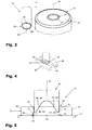
- the forming tool 13 is provided with the forming die 11 provided as the upper die and the forming die 12 provided as the lower die FIG. 3 shown.
- the stroke axis 14 is indicated by dash-dotted lines on both the forming die 11 and on the forming die 12, along which the forming die 11 is lowered for pressure forming a connecting web 23 relative to the forming die 12 with a constraintshub.
- the free end of the Umformstempels 11 is provided with an inner cone 28.
- the lateral surface of the inner cone 28 bounded together with the hubachsparallelen cylindrical outer surface of the Umformstkovs 11 and perpendicular to the lifting axis 14 extending flat end face 26 has a trapezoidal cross-section of the punch-side forming 24.
- the upper boundary of the trapezoidal cross-section of the punch-side forming member 24 is in FIG. 5 indicated by an imaginary dashed line.
- the die-side forming member 25 projects from a support surface 29 of the forming die 12 to the forming die 11.
- the cross-section of the die-side forming member 25 has the shape of an isosceles triangle whose base lies in the bearing surface 29 of the forming die 12 and the tip of which forms the linear end face 27 of the die-side forming member 25.
- Both the punch-side forming member 24 and the die-side forming member 25 extend endlessly along a circular line and concentric with the lifting axis 14. In the transverse direction of the lifting axis 14, the punch-side forming member 24 and the die-side forming member 25 are offset from each other, wherein the flat end face 26 of the punch-side forming member 24 within the linear end face 27 of the die-side forming member 25 is located.
- the machined metal sheet 15 is positioned by means of the coordinate guide 16 of the machine tool 1 relative to the forming tool 13 inserted at the forming station 6 in such a way that the forming tool 13 assumes a machining standby position with respect to the connecting web 23 to be formed.
- the forming die 11 of the forming tool 13 is spaced along the lifting axis 14 from the top of the connecting web 23 and the workpiece parts adjacent thereto.
- the end face 27 of the die-side forming member 25 has along the lifting axis 14 at a minimum distance from the underside of the connecting web 23 and connected by this workpiece parts.
- the vertical projection of the flat end face 26 of the punch-side forming member 24 of arranged in the machining standby Umformstempels 11 extends to the top of the machined plate 15 at both ends of the connecting web 23 via a projection 30 of the connecting web 23rd on the respective workpiece part addition. This is shown in FIG. 4 , where in FIG. 4 only the vertical projection of the radially outer boundary line of the flat end face 26 of the punch-side forming member 24 is shown.
- the vertical projection of the linear end face 27 of the die-side forming member 25 extends concentrically with the machined plate 15 and radially outside the vertical projection of the end face 26 of the punch-side forming member 24th
- the forming die 11 is moved with a machining stroke along the lifting axis 14 in the direction of the forming die 12 into a stroke end position.
- the machining stroke is controlled path-dependent, in the example according to the FIG. 13 the control of the machining stroke is dependent on the force.
- the amount of processing performed by the forming die 11 relative to the forming die 12 processing is variably adjustable and depends in particular on the desired residual thickness of the connecting web 23 after forming.
- the traveled by the forming die 11 along the lifting axis 14 Path is detected by means of a conventional position measuring system and forms the basis for the control of the lifting drive of the machine tool. 1
- the residual thickness of the connecting web 23 is also determined by the height of the die-side forming member 25 measured along the stroke axis 14.
- the conditions at stroke end position of the Umformstempels 11 are in FIG. 5 illustrated.
- the connecting web 23, the skeleton grid 18 and the sheet metal part 20 are under the effect the loading by the forming die 11 is pressed with its underside against the support surface 29 of the forming die 12.
- the forming die 11 is immersed in the course of the processing stroke with diametrically opposite organ portions of the punch-side forming member 24 at both ends of the connecting web 23 in this and in the adjacent areas of the residual grid 18 and the sheet metal part 20.
- a workpiece side 31 of the punch-side forming member 24 is the residual grid 18, a workpiece side 32 of the punch-side forming member 24 facing the sheet metal part 20.
- Web sides 33, 34 of the punch-side forming member 24 point towards the connecting web 23 and are accordingly remote from the residual grid 18 and the sheet metal part 20.
- the die-side forming member 25 has two diametrically opposite organ sections at the ends of the connecting web in this and in the vicinity of the web areas of the residual grid 18 and of the sheet metal part 20 is pressed.
- Workpiece sides 35, 36 of the die-side forming member 25 are facing the skeleton grid 18 and the sheet metal part 20, web sides 37, 38 of the die-side forming member 25 are remote from the skeleton grid 18 and from the sheet metal part 20.
- the punch-side forming member 24 forming surfaces 40, 41 on.
- the web sides 37, 38 of the die-side forming member 25 forming surfaces 42, 43 are provided.
- the forming surfaces 40, 41 of the stem-side forming member 24 extending from the end face 26 of the punch-side forming member 24 along the lifting axis 14 of the workpiece sides 31, 32 of the punch-side forming member 24 away. Accordingly, the forming surfaces 42, 43 of the die-side forming member 25 remove along the lifting axis 24 of the workpiece sides 35, 36 of the die-side forming member 25th
- the cross section of the connecting web 23 is reduced by the pressure forming by means of the forming tool 13, the cross section of the connecting web 23 along the lifting axis 14. Due to the excess of the diameter of the end faces 26, 27 of the punch-side forming member 24 and the die-side forming member 25 relative to the connecting web 23 are the cross-section reduced Lugs of the connecting web 23 on the skeleton grid 18 and on the sheet metal part 20 relative to the separating surfaces 39 in the interior of the residual grid 18 and the sheet metal part 20 set back.
- a corresponding offset of the projections of the cross-section reduced connecting web 23 on the skeleton grid 18 and on the sheet metal part 20 is established when the separating surfaces 39 on the skeleton grid 18 and the sheet metal part 20 already at the pressure forming of the connecting webs 23 upstream separating processing of the sheet 15 with a appropriate return ( FIG. 6 ).
- the connecting web 23 and not even an immediately adjacent to the connecting web 23 of the residual grid 18 and the sheet metal part 20 is to be processed in the subsequent to the separating processing of the sheet 15 pressure forming. Accordingly, in the case of the processing situation, according to FIG. 6 for pressure forming the connecting web 23 to apply a lower force than in the proportions according to FIG. 4 ,
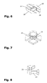
- FIGS. 7 and 8 illustrate by way of example the processing of X-shaped crossing processing webs 23, as they are in the art FIG. 2 between the sheet metal parts 19, 20, 21, 22 are provided.
- FIG. 7 refers to the case that not only the connecting webs 23 themselves but also directly adjacent workpiece areas are to be reshaped while according to FIG. 8 immediately adjacent to the connecting webs 23 adjacent workpiece areas have already been removed in the previous separating processing of the sheet 15 and consequently only the connecting webs 23 must be transformed.
- FIG. 9 shows a provided between two incompletely separate workpiece parts connecting web 23 which, like the rest of the machined workpiece is made of a resilient material and in the incomplete separation of the adjacent workpiece parts with a meandering shape has been created. Due to the material and due to its special shape of the connecting web 23 is resilient and accordingly forms a solid-state joint between the two adjacent workpiece parts. If the connecting web 23 according to FIG. 9 in the in FIG. 5 illustrated manner by the forming die 11 and the forming die 12 of the forming die 13 pressurized, so sets the connecting web 23 due to its resilience of the pressure deformation only a relatively small resistance. The resilience of the connecting web 23 facilitates the displacement of plasticized material of the connecting web 23 of the workpiece sides 31, 32, 35, 36 of the punch-side forming member 24 and the die-side forming member 25 away.
- the Figures 10a, 10b and 10c show from the forming tool 13 structurally deviating forming tools 13/1, 13/2, 13/3 each in the circumference of a Umformstkovs 11/1, 11/2, 11/3.
- a punch-side forming member 24/1 of the forming die 11/1 unlike the punch-side forming member 24 of the forming die 11 has an elliptical shape.
- the forming die 11/2 is divided in a plane parallel to the lifting axis 14 and thus has a two-part punch-side forming member 24/2, each segment of the punch-side forming member 24/2 is semi-circular.
- the forming die 11/3 has resulted from the forming die 11/1 by division along a plane parallel to the lifting axis 14 extending plane.
- a punch-side forming member 24/3 of Umformstkovs 11/3 is thus segmented and comprises two identical halves.
- the Umformstempeln 11/1, 11/2, 11/3 are not shown forming dies assigned to the die-side forming members whose geometry is adapted to the geometry of the punch-side forming members 24/1, 24/2, 24/3 and the rest with the matrizen documenten Forming member 25 of the forming die 12 of the forming tool 13 match.
- FIGS. 11 and 12 machining strategies are illustrated, according to which connecting webs 23 between incompletely separated workpiece parts by means of forming tools 13/1, 13/2, 13/3 can be pressure-formed.
- FIG. 11 is carried out with several processing strokes of the forming tool 13/1 successively at the ends of connecting webs 23, a pressure forming.
- the forming punch 11/1 and the forming die associated therewith are turned about the lifting axis 14 by rotating the upper tool holder 9 and the lower tool holder 10 of the machine tool 1.
- the machined plate 15 is positioned by means of the coordinate guide 16 of the machine tool 1 relative to the forming tool 13/1.
- a simple connecting web 23 is processed by means of the forming tool 13/2.
- the forming tool 13/3 is used for pressure forming two X-shaped crossing connecting webs 23, the forming tool 13/3 is used.
- the forming 13/2, 13/3 perform with a single machining stroke a pressure deformation at both ends of a connecting web 23, wherein for the processing of the two X-shaped crossing connecting webs 23 two successive processing strokes of the forming 13/3 are required and the forming tool thirteenth / 3 is rotated about the lifting axis 14 after the first processing stroke.
- FIG. 13 is a tool part of a forming tool 13/4 formed as a forming die 11/4.
- the forming die 11/4 is a second tool part in an FIG. 13 not shown forming die 12 according to FIG. 3 assigned.
- a forming unit 44 of the forming die 11/4 agrees with the forming die 11 according to FIG. 3 match.
- the forming die 11/4 ends in a punch-side forming member 24/4 with trapezoidal cross-section.
- the forming die 11/4 has cheeks 45, 46 which protrude toward the punch-side forming member 24/4 of the forming die 11/4 along the lifting axis 14 to the forming die 12, not shown, and thereby projections 47, 48 of the forming die 11/4 training.
- the metal sheet 15 previously worked on and the forming tool 13/4 are positioned relative to one another in such a way that, in the case of a machining stroke carried out by the forming punch 11/4 towards the forming die 12, the connecting web 23 to be formed between the projections 47, 48 of FIG Umformstempel 11/4 comes to rest.
- the projections 47, 48 of the forming die 11/4 With their end faces leading along the stroke axis 14, rest on the contact surface 29 of the forming die 12.
- the projection of the projections 47, 48 relative to the punch-side forming member 24/4 is dimensioned such that at stroke end position of Umformstempels 11/4 the end face of the punch-side forming member 24/4 of the end face of the die-side forming member 25 along the lifting axis 14 has a distance , which corresponds to the desired residual thickness of the pressure-formed connecting web 23.
- the stroke end position of the forming die 11/4 engages over the formed connecting web 23 portal-like.
- the projections 47, 48 of the forming die 11/4 are laterally adjacent to the connecting web 23 in the manner of portal supports.
- the executed by the forming die 11/4 relative to the forming die 12 processing stroke is force-controlled.
- the programmable numerical control of the machine tool 1 is for this purpose in FIG. 13 suggestively illustrated stroke control device 49 integrated for the lifting drive of the forming tool 13/4.
- the stroke control device 49 comprises a force-measuring device 50, an evaluation device 51 and an actuating device 52.
- the force-measuring device 50 By means of the force-measuring device 50, the amount of the supporting force with which the forming punch 11/4 of the forming tool 13/4 is supported along the lifting axis 14 on the forming die 12 is measured.
- the evaluation device 51 the measured actual amount of the supporting force is compared with a stored in the stroke control device 49 limit amount of the supporting force. If the measured actual amount of the supporting force reaches the predetermined limit, this indicates that the forming punch 11/4 reaches its stroke end position along the lifting axis 14 Has.
- the evaluation device 51 then generates a switching signal for the actuating device 52.
- the actuating device 52 actuates the lifting drive of the forming tool 13/4 to the effect that the processing die of the forming punch 11/4 directed towards the forming die 12 terminates and engages Return stroke of the forming die 11/4 is initiated in the opposite direction of the machining stroke.
- FIG. 14 FIG. 12 illustrates a process step performed in the processing of the sheet 15 in the illustrated example case before the pressure forming of the connecting webs 23.
- 23 incompletely separated from each other sheet metal parts are edged on the bottom by separating processing while leaving elastic connecting webs.
- a forming roller 53 which is loaded in the lower tool holder 10 at the forming station 6 of the machine tool 1.
- the forming roller 53 acts in the processing of the sheet metal parts of a previously separated processed sheet with a in FIG. 14 Not shown counter-pressure roller together, which is loaded into the upper tool holder 9 of the machine tool 1 and which bears against the top of the machined sheet with a cylindrical outer surface.
- the forming roller 53 is provided with a biconical bead 54, which has two conical forming surfaces 55, 56.
- the sheet metal parts in the example according to FIG. 2 the sheet metal parts 19, 20, 21, 22 of the machined plate 15, from the associated skeleton grid (skeleton grid 18 in FIG. 2 ) solved. Due to the cross-sectional reduction of the connecting webs 23, shaking of the machined sheet is sufficient for this purpose. Due to the load acting thereupon, the connecting webs 23 break into the fracture zones produced by pressure forming, wherein, due to the geometry of the punch-side forming members 24, 24/1, 24/2, 24/3, 24/4 and the associated die-side forming members of the forming tools 13, 13 / 1, 13/2, 13/3, 13/4 remain on the sheet metal parts no or at most minimal traces of the connecting webs 23.
- the diameter-reduced projections of the connecting webs 23 are set back in the interior of the sheet metal parts, so also protrude on the sheet metal parts remains the connecting webs 23 not over the created before the pressure forming of the connecting webs 23 separating surfaces of the sheet metal parts.
Priority Applications (4)
| Application Number | Priority Date | Filing Date | Title |
|---|---|---|---|
| EP15165673.3A EP3088096B1 (de) | 2015-04-29 | 2015-04-29 | Vorrichtungen und verfahren zum druckumformen von verbindungsstegen zwischen werkstückteilen eines plattenartigen werkstücks |
| JP2016090884A JP6738191B2 (ja) | 2015-04-29 | 2016-04-28 | プレート状のワークのワーク部分の間における結合ウェブを押圧変形する装置および方法 |
| US15/142,666 US10058907B2 (en) | 2015-04-29 | 2016-04-29 | Devices and methods for pressure forming connecting webs between workpiece parts of a plate-like workpiece |
| CN201610280382.7A CN106077278B (zh) | 2015-04-29 | 2016-04-29 | 将板形工件的工件部分间的连接筋压力成形的装置和方法 |
Applications Claiming Priority (1)
| Application Number | Priority Date | Filing Date | Title |
|---|---|---|---|
| EP15165673.3A EP3088096B1 (de) | 2015-04-29 | 2015-04-29 | Vorrichtungen und verfahren zum druckumformen von verbindungsstegen zwischen werkstückteilen eines plattenartigen werkstücks |
Publications (2)
| Publication Number | Publication Date |
|---|---|
| EP3088096A1 true EP3088096A1 (de) | 2016-11-02 |
| EP3088096B1 EP3088096B1 (de) | 2021-07-07 |
Family
ID=53008390
Family Applications (1)
| Application Number | Title | Priority Date | Filing Date |
|---|---|---|---|
| EP15165673.3A Active EP3088096B1 (de) | 2015-04-29 | 2015-04-29 | Vorrichtungen und verfahren zum druckumformen von verbindungsstegen zwischen werkstückteilen eines plattenartigen werkstücks |
Country Status (4)
| Country | Link |
|---|---|
| US (1) | US10058907B2 (zh) |
| EP (1) | EP3088096B1 (zh) |
| JP (1) | JP6738191B2 (zh) |
| CN (1) | CN106077278B (zh) |
Cited By (1)
| Publication number | Priority date | Publication date | Assignee | Title |
|---|---|---|---|---|
| DE102022127687A1 (de) | 2022-10-20 | 2024-04-25 | TRUMPF Werkzeugmaschinen SE + Co. KG | Verfahren zum Erzeugen eines dickenreduzierten Verbindungsstegs beim Schneiden eines Werkstückteils aus einem plattenartigen Werkstück sowie zugehöriges Steuerungsprogrammprodukt |
Families Citing this family (1)
| Publication number | Priority date | Publication date | Assignee | Title |
|---|---|---|---|---|
| US20210162534A1 (en) * | 2018-04-13 | 2021-06-03 | Ipg Photonics Corporation | Laser assisted machining of sheet material |
Citations (3)
| Publication number | Priority date | Publication date | Assignee | Title |
|---|---|---|---|---|
| US4362078A (en) * | 1980-03-25 | 1982-12-07 | Akzona Incorporated | Method of blanking |
| US5655401A (en) | 1995-11-13 | 1997-08-12 | Interbold | Tabbing tool and method |
| DE102012011767A1 (de) * | 2012-05-10 | 2013-11-14 | Technische Universität München | Zerteilen eines Werkstücks |
Family Cites Families (13)
| Publication number | Priority date | Publication date | Assignee | Title |
|---|---|---|---|---|
| JPS57146428A (en) * | 1981-03-06 | 1982-09-09 | Taiho Kogyo Co Ltd | Piercing method for plate |
| JP2661287B2 (ja) * | 1989-01-19 | 1997-10-08 | トヨタ自動車株式会社 | だれ・かえり防止打抜き加工法 |
| JPH0428439A (ja) * | 1990-05-22 | 1992-01-31 | Matsushita Electric Ind Co Ltd | 軸受プレートの製造方法 |
| JPH06142784A (ja) * | 1992-11-10 | 1994-05-24 | Komatsu Ltd | パンチプレス加工におけるジョイント加工方法 |
| FR2751570B1 (fr) | 1996-07-25 | 1998-09-04 | Lorraine Laminage | Procede de decoupage d'une piece dans un flan de tole |
| JP3782853B2 (ja) * | 1996-08-22 | 2006-06-07 | 日清紡績株式会社 | パンチプレス装置における多数穿孔金属板の製造方法 |
| JP3339363B2 (ja) * | 1996-11-25 | 2002-10-28 | トヨタ車体株式会社 | 半抜き成形方法およびこれに使用する冷間鍛造型 |
| JPH11300428A (ja) * | 1998-04-22 | 1999-11-02 | Amada Co Ltd | パンチプレスの加工方法及びその装置 |
| DE602005015303D1 (de) | 2004-04-09 | 2009-08-20 | Toyota Boshoku Kk | Schervorrichtung |
| DE112006000245T5 (de) * | 2005-01-25 | 2007-12-13 | Aisin AW Co., Ltd., Anjo | Stanzvorrichtung, Stanzverfahren und Stanzprodukt |
| JP2007000901A (ja) * | 2005-06-24 | 2007-01-11 | Murata Mach Ltd | パンチプレスのバリ取りツール |
| JP2013059777A (ja) * | 2011-09-12 | 2013-04-04 | Toyota Motor Corp | ホットプレス加工方法およびホットプレス加工装置 |
| CN204159719U (zh) | 2014-07-26 | 2015-02-18 | 保定苏博汽车零件制造有限公司 | 一种半剪模 |
-
2015
- 2015-04-29 EP EP15165673.3A patent/EP3088096B1/de active Active
-
2016
- 2016-04-28 JP JP2016090884A patent/JP6738191B2/ja not_active Expired - Fee Related
- 2016-04-29 CN CN201610280382.7A patent/CN106077278B/zh active Active
- 2016-04-29 US US15/142,666 patent/US10058907B2/en active Active
Patent Citations (3)
| Publication number | Priority date | Publication date | Assignee | Title |
|---|---|---|---|---|
| US4362078A (en) * | 1980-03-25 | 1982-12-07 | Akzona Incorporated | Method of blanking |
| US5655401A (en) | 1995-11-13 | 1997-08-12 | Interbold | Tabbing tool and method |
| DE102012011767A1 (de) * | 2012-05-10 | 2013-11-14 | Technische Universität München | Zerteilen eines Werkstücks |
Cited By (1)
| Publication number | Priority date | Publication date | Assignee | Title |
|---|---|---|---|---|
| DE102022127687A1 (de) | 2022-10-20 | 2024-04-25 | TRUMPF Werkzeugmaschinen SE + Co. KG | Verfahren zum Erzeugen eines dickenreduzierten Verbindungsstegs beim Schneiden eines Werkstückteils aus einem plattenartigen Werkstück sowie zugehöriges Steuerungsprogrammprodukt |
Also Published As
| Publication number | Publication date |
|---|---|
| CN106077278B (zh) | 2019-04-30 |
| US20160318088A1 (en) | 2016-11-03 |
| EP3088096B1 (de) | 2021-07-07 |
| US10058907B2 (en) | 2018-08-28 |
| JP2017001096A (ja) | 2017-01-05 |
| JP6738191B2 (ja) | 2020-08-12 |
| CN106077278A (zh) | 2016-11-09 |
Similar Documents
| Publication | Publication Date | Title |
|---|---|---|
| EP0720695B2 (de) | Selbststanzende befestigungsvorrichtung | |
| EP2008736B1 (de) | Werkzeugmaschine und Verfahren zum Ausschleusen eines Werkstückteils | |
| EP1740327A1 (de) | Werkzeug, maschine sowie verfahren zum entgraten von schnittkanten an werkstücken | |
| DE69934444T2 (de) | Entgratverfahren | |
| EP3052256B1 (de) | Biegepresse und biegeverfahren | |
| EP2086699B1 (de) | Verfahren zur gewinnung von werkstückausschnitten aus einem plattenartigen werkstück | |
| EP3219429A1 (de) | Werkzeugmaschine mit einer stanzvorrichtung und einer laserbearbeitungsvorrichtung sowie verfahren zum bearbeiten von werkstücken mittels einer derartigen werkzeugmaschine | |
| EP3088095B1 (de) | Verfahren zum bearbeiten von plattenartigen werkstücken | |
| EP2532452B1 (de) | Verfahren zum Stanzen und Richten von Blechen | |
| DE102014100645A1 (de) | Werkzeug zum Scherschneiden und Verfahren | |
| EP3088096B1 (de) | Vorrichtungen und verfahren zum druckumformen von verbindungsstegen zwischen werkstückteilen eines plattenartigen werkstücks | |
| EP1623782B1 (de) | Verfahren und Vorrichtung zum Umformen und Schneiden von hochfesten Blechen | |
| EP3088097B1 (de) | Vorrichtungen und verfahren zum druckumformen von verbindungsstegen zwischen werkstückteilen eines plattenartigen werkstücks | |
| EP2502716A1 (de) | Werkzeug für eine Blechbearbeitungsmaschine und Verfahren zum Trennen einer Folie | |
| DE102010033191B4 (de) | Vorrichtung zum Schneiden von hochfesten Werkstücken | |
| WO2009065694A1 (de) | Verfahren zum herstellen einer gratfreien schnittfläche und vorrichtung zur durchführung des verfahrens | |
| DE102006053223B3 (de) | Loch- und Durchzugsstempel | |
| DE19643076C2 (de) | Vorrichtung zum in einem Arbeitsgang erfolgenden Stanzen und Fügen mindestens zweier Blechteile | |
| CH642574A5 (de) | Verfahren bei der herstellung eines kurbelarmes fuer eine geschweisste kurbelwelle und pressausruestung zur ausuebung des verfahrens. | |
| DE10151659B4 (de) | Verfahren zum Fügen von zumindest zwei Bauteilen und Vorrichtung hierfür | |
| DE102015114074B4 (de) | Vorrichtung und Verfahren zum Trennen eines Werkstückes | |
| DE60112120T2 (de) | Vorrichtung zum verbinden von duktilem material | |
| EP3606687A1 (de) | Verfahren und vorrichtung zum schneiden eines werkstücks | |
| DE102018112056B4 (de) | Verfahren und Vorrichtung zum Schneiden eines Werkstücks | |
| DE102015115170B4 (de) | Verfahren und Vorrichtung zum einstufigen Beschneiden großer Schnittlängen |
Legal Events
| Date | Code | Title | Description |
|---|---|---|---|
| PUAI | Public reference made under article 153(3) epc to a published international application that has entered the european phase |
Free format text: ORIGINAL CODE: 0009012 |
|
| AK | Designated contracting states |
Kind code of ref document: A1 Designated state(s): AL AT BE BG CH CY CZ DE DK EE ES FI FR GB GR HR HU IE IS IT LI LT LU LV MC MK MT NL NO PL PT RO RS SE SI SK SM TR |
|
| AX | Request for extension of the european patent |
Extension state: BA ME |
|
| STAA | Information on the status of an ep patent application or granted ep patent |
Free format text: STATUS: REQUEST FOR EXAMINATION WAS MADE |
|
| 17P | Request for examination filed |
Effective date: 20170502 |
|
| RBV | Designated contracting states (corrected) |
Designated state(s): AL AT BE BG CH CY CZ DE DK EE ES FI FR GB GR HR HU IE IS IT LI LT LU LV MC MK MT NL NO PL PT RO RS SE SI SK SM TR |
|
| STAA | Information on the status of an ep patent application or granted ep patent |
Free format text: STATUS: EXAMINATION IS IN PROGRESS |
|
| 17Q | First examination report despatched |
Effective date: 20190129 |
|
| STAA | Information on the status of an ep patent application or granted ep patent |
Free format text: STATUS: EXAMINATION IS IN PROGRESS |
|
| GRAP | Despatch of communication of intention to grant a patent |
Free format text: ORIGINAL CODE: EPIDOSNIGR1 |
|
| STAA | Information on the status of an ep patent application or granted ep patent |
Free format text: STATUS: GRANT OF PATENT IS INTENDED |
|
| INTG | Intention to grant announced |
Effective date: 20210311 |
|
| GRAS | Grant fee paid |
Free format text: ORIGINAL CODE: EPIDOSNIGR3 |
|
| GRAA | (expected) grant |
Free format text: ORIGINAL CODE: 0009210 |
|
| STAA | Information on the status of an ep patent application or granted ep patent |
Free format text: STATUS: THE PATENT HAS BEEN GRANTED |
|
| AK | Designated contracting states |
Kind code of ref document: B1 Designated state(s): AL AT BE BG CH CY CZ DE DK EE ES FI FR GB GR HR HU IE IS IT LI LT LU LV MC MK MT NL NO PL PT RO RS SE SI SK SM TR |
|
| REG | Reference to a national code |
Ref country code: GB Ref legal event code: FG4D Free format text: NOT ENGLISH |
|
| REG | Reference to a national code |
Ref country code: AT Ref legal event code: REF Ref document number: 1408061 Country of ref document: AT Kind code of ref document: T Effective date: 20210715 |
|
| REG | Reference to a national code |
Ref country code: DE Ref legal event code: R096 Ref document number: 502015014898 Country of ref document: DE |
|
| REG | Reference to a national code |
Ref country code: IE Ref legal event code: FG4D Free format text: LANGUAGE OF EP DOCUMENT: GERMAN |
|
| REG | Reference to a national code |
Ref country code: LT Ref legal event code: MG9D |
|
| REG | Reference to a national code |
Ref country code: NL Ref legal event code: MP Effective date: 20210707 |
|
| PG25 | Lapsed in a contracting state [announced via postgrant information from national office to epo] |
Ref country code: SE Free format text: LAPSE BECAUSE OF FAILURE TO SUBMIT A TRANSLATION OF THE DESCRIPTION OR TO PAY THE FEE WITHIN THE PRESCRIBED TIME-LIMIT Effective date: 20210707 Ref country code: RS Free format text: LAPSE BECAUSE OF FAILURE TO SUBMIT A TRANSLATION OF THE DESCRIPTION OR TO PAY THE FEE WITHIN THE PRESCRIBED TIME-LIMIT Effective date: 20210707 Ref country code: HR Free format text: LAPSE BECAUSE OF FAILURE TO SUBMIT A TRANSLATION OF THE DESCRIPTION OR TO PAY THE FEE WITHIN THE PRESCRIBED TIME-LIMIT Effective date: 20210707 Ref country code: FI Free format text: LAPSE BECAUSE OF FAILURE TO SUBMIT A TRANSLATION OF THE DESCRIPTION OR TO PAY THE FEE WITHIN THE PRESCRIBED TIME-LIMIT Effective date: 20210707 Ref country code: ES Free format text: LAPSE BECAUSE OF FAILURE TO SUBMIT A TRANSLATION OF THE DESCRIPTION OR TO PAY THE FEE WITHIN THE PRESCRIBED TIME-LIMIT Effective date: 20210707 Ref country code: NL Free format text: LAPSE BECAUSE OF FAILURE TO SUBMIT A TRANSLATION OF THE DESCRIPTION OR TO PAY THE FEE WITHIN THE PRESCRIBED TIME-LIMIT Effective date: 20210707 Ref country code: PT Free format text: LAPSE BECAUSE OF FAILURE TO SUBMIT A TRANSLATION OF THE DESCRIPTION OR TO PAY THE FEE WITHIN THE PRESCRIBED TIME-LIMIT Effective date: 20211108 Ref country code: NO Free format text: LAPSE BECAUSE OF FAILURE TO SUBMIT A TRANSLATION OF THE DESCRIPTION OR TO PAY THE FEE WITHIN THE PRESCRIBED TIME-LIMIT Effective date: 20211007 Ref country code: BG Free format text: LAPSE BECAUSE OF FAILURE TO SUBMIT A TRANSLATION OF THE DESCRIPTION OR TO PAY THE FEE WITHIN THE PRESCRIBED TIME-LIMIT Effective date: 20211007 Ref country code: LT Free format text: LAPSE BECAUSE OF FAILURE TO SUBMIT A TRANSLATION OF THE DESCRIPTION OR TO PAY THE FEE WITHIN THE PRESCRIBED TIME-LIMIT Effective date: 20210707 |
|
| PG25 | Lapsed in a contracting state [announced via postgrant information from national office to epo] |
Ref country code: PL Free format text: LAPSE BECAUSE OF FAILURE TO SUBMIT A TRANSLATION OF THE DESCRIPTION OR TO PAY THE FEE WITHIN THE PRESCRIBED TIME-LIMIT Effective date: 20210707 Ref country code: LV Free format text: LAPSE BECAUSE OF FAILURE TO SUBMIT A TRANSLATION OF THE DESCRIPTION OR TO PAY THE FEE WITHIN THE PRESCRIBED TIME-LIMIT Effective date: 20210707 Ref country code: GR Free format text: LAPSE BECAUSE OF FAILURE TO SUBMIT A TRANSLATION OF THE DESCRIPTION OR TO PAY THE FEE WITHIN THE PRESCRIBED TIME-LIMIT Effective date: 20211008 |
|
| REG | Reference to a national code |
Ref country code: DE Ref legal event code: R097 Ref document number: 502015014898 Country of ref document: DE |
|
| PG25 | Lapsed in a contracting state [announced via postgrant information from national office to epo] |
Ref country code: DK Free format text: LAPSE BECAUSE OF FAILURE TO SUBMIT A TRANSLATION OF THE DESCRIPTION OR TO PAY THE FEE WITHIN THE PRESCRIBED TIME-LIMIT Effective date: 20210707 |
|
| PLBE | No opposition filed within time limit |
Free format text: ORIGINAL CODE: 0009261 |
|
| STAA | Information on the status of an ep patent application or granted ep patent |
Free format text: STATUS: NO OPPOSITION FILED WITHIN TIME LIMIT |
|
| PG25 | Lapsed in a contracting state [announced via postgrant information from national office to epo] |
Ref country code: SM Free format text: LAPSE BECAUSE OF FAILURE TO SUBMIT A TRANSLATION OF THE DESCRIPTION OR TO PAY THE FEE WITHIN THE PRESCRIBED TIME-LIMIT Effective date: 20210707 Ref country code: SK Free format text: LAPSE BECAUSE OF FAILURE TO SUBMIT A TRANSLATION OF THE DESCRIPTION OR TO PAY THE FEE WITHIN THE PRESCRIBED TIME-LIMIT Effective date: 20210707 Ref country code: RO Free format text: LAPSE BECAUSE OF FAILURE TO SUBMIT A TRANSLATION OF THE DESCRIPTION OR TO PAY THE FEE WITHIN THE PRESCRIBED TIME-LIMIT Effective date: 20210707 Ref country code: EE Free format text: LAPSE BECAUSE OF FAILURE TO SUBMIT A TRANSLATION OF THE DESCRIPTION OR TO PAY THE FEE WITHIN THE PRESCRIBED TIME-LIMIT Effective date: 20210707 Ref country code: CZ Free format text: LAPSE BECAUSE OF FAILURE TO SUBMIT A TRANSLATION OF THE DESCRIPTION OR TO PAY THE FEE WITHIN THE PRESCRIBED TIME-LIMIT Effective date: 20210707 Ref country code: AL Free format text: LAPSE BECAUSE OF FAILURE TO SUBMIT A TRANSLATION OF THE DESCRIPTION OR TO PAY THE FEE WITHIN THE PRESCRIBED TIME-LIMIT Effective date: 20210707 |
|
| 26N | No opposition filed |
Effective date: 20220408 |
|
| PG25 | Lapsed in a contracting state [announced via postgrant information from national office to epo] |
Ref country code: IT Free format text: LAPSE BECAUSE OF FAILURE TO SUBMIT A TRANSLATION OF THE DESCRIPTION OR TO PAY THE FEE WITHIN THE PRESCRIBED TIME-LIMIT Effective date: 20210707 |
|
| PGFP | Annual fee paid to national office [announced via postgrant information from national office to epo] |
Ref country code: FR Payment date: 20220421 Year of fee payment: 8 |
|
| REG | Reference to a national code |
Ref country code: CH Ref legal event code: PL |
|
| REG | Reference to a national code |
Ref country code: BE Ref legal event code: MM Effective date: 20220430 |
|
| PG25 | Lapsed in a contracting state [announced via postgrant information from national office to epo] |
Ref country code: MC Free format text: LAPSE BECAUSE OF FAILURE TO SUBMIT A TRANSLATION OF THE DESCRIPTION OR TO PAY THE FEE WITHIN THE PRESCRIBED TIME-LIMIT Effective date: 20210707 Ref country code: LU Free format text: LAPSE BECAUSE OF NON-PAYMENT OF DUE FEES Effective date: 20220429 Ref country code: LI Free format text: LAPSE BECAUSE OF NON-PAYMENT OF DUE FEES Effective date: 20220430 Ref country code: CH Free format text: LAPSE BECAUSE OF NON-PAYMENT OF DUE FEES Effective date: 20220430 |
|
| PG25 | Lapsed in a contracting state [announced via postgrant information from national office to epo] |
Ref country code: BE Free format text: LAPSE BECAUSE OF NON-PAYMENT OF DUE FEES Effective date: 20220430 |
|
| PG25 | Lapsed in a contracting state [announced via postgrant information from national office to epo] |
Ref country code: IE Free format text: LAPSE BECAUSE OF NON-PAYMENT OF DUE FEES Effective date: 20220429 |
|
| REG | Reference to a national code |
Ref country code: AT Ref legal event code: MM01 Ref document number: 1408061 Country of ref document: AT Kind code of ref document: T Effective date: 20220429 |
|
| PG25 | Lapsed in a contracting state [announced via postgrant information from national office to epo] |
Ref country code: AT Free format text: LAPSE BECAUSE OF NON-PAYMENT OF DUE FEES Effective date: 20220429 |
|
| PGFP | Annual fee paid to national office [announced via postgrant information from national office to epo] |
Ref country code: DE Payment date: 20230420 Year of fee payment: 9 |
|
| PGFP | Annual fee paid to national office [announced via postgrant information from national office to epo] |
Ref country code: GB Payment date: 20230419 Year of fee payment: 9 |
|
| PG25 | Lapsed in a contracting state [announced via postgrant information from national office to epo] |
Ref country code: FR Free format text: LAPSE BECAUSE OF NON-PAYMENT OF DUE FEES Effective date: 20230430 |
|
| PG25 | Lapsed in a contracting state [announced via postgrant information from national office to epo] |
Ref country code: HU Free format text: LAPSE BECAUSE OF FAILURE TO SUBMIT A TRANSLATION OF THE DESCRIPTION OR TO PAY THE FEE WITHIN THE PRESCRIBED TIME-LIMIT; INVALID AB INITIO Effective date: 20150429 |