EP3086898B1 - Schweissroboter und verfahren zum betreiben einer laserschweissvorrichtung - Google Patents
Schweissroboter und verfahren zum betreiben einer laserschweissvorrichtung Download PDFInfo
- Publication number
- EP3086898B1 EP3086898B1 EP14812549.5A EP14812549A EP3086898B1 EP 3086898 B1 EP3086898 B1 EP 3086898B1 EP 14812549 A EP14812549 A EP 14812549A EP 3086898 B1 EP3086898 B1 EP 3086898B1
- Authority
- EP
- European Patent Office
- Prior art keywords
- welding
- laser beam
- time period
- producing
- control device
- Prior art date
- Legal status (The legal status is an assumption and is not a legal conclusion. Google has not performed a legal analysis and makes no representation as to the accuracy of the status listed.)
- Active
Links
Images

Classifications
-
- B—PERFORMING OPERATIONS; TRANSPORTING
- B23—MACHINE TOOLS; METAL-WORKING NOT OTHERWISE PROVIDED FOR
- B23K—SOLDERING OR UNSOLDERING; WELDING; CLADDING OR PLATING BY SOLDERING OR WELDING; CUTTING BY APPLYING HEAT LOCALLY, e.g. FLAME CUTTING; WORKING BY LASER BEAM
- B23K26/00—Working by laser beam, e.g. welding, cutting or boring
- B23K26/08—Devices involving relative movement between laser beam and workpiece
- B23K26/0869—Devices involving movement of the laser head in at least one axial direction
- B23K26/0876—Devices involving movement of the laser head in at least one axial direction in at least two axial directions
- B23K26/0884—Devices involving movement of the laser head in at least one axial direction in at least two axial directions in at least three axial directions, e.g. manipulators, robots
-
- B—PERFORMING OPERATIONS; TRANSPORTING
- B23—MACHINE TOOLS; METAL-WORKING NOT OTHERWISE PROVIDED FOR
- B23K—SOLDERING OR UNSOLDERING; WELDING; CLADDING OR PLATING BY SOLDERING OR WELDING; CUTTING BY APPLYING HEAT LOCALLY, e.g. FLAME CUTTING; WORKING BY LASER BEAM
- B23K26/00—Working by laser beam, e.g. welding, cutting or boring
- B23K26/02—Positioning or observing the workpiece, e.g. with respect to the point of impact; Aligning, aiming or focusing the laser beam
- B23K26/06—Shaping the laser beam, e.g. by masks or multi-focusing
- B23K26/062—Shaping the laser beam, e.g. by masks or multi-focusing by direct control of the laser beam
- B23K26/0626—Energy control of the laser beam
-
- B—PERFORMING OPERATIONS; TRANSPORTING
- B23—MACHINE TOOLS; METAL-WORKING NOT OTHERWISE PROVIDED FOR
- B23K—SOLDERING OR UNSOLDERING; WELDING; CLADDING OR PLATING BY SOLDERING OR WELDING; CUTTING BY APPLYING HEAT LOCALLY, e.g. FLAME CUTTING; WORKING BY LASER BEAM
- B23K26/00—Working by laser beam, e.g. welding, cutting or boring
- B23K26/20—Bonding
- B23K26/21—Bonding by welding
- B23K26/24—Seam welding
Definitions
- the invention relates to a welding robot and a method for operating a laser welding device.
- the DE 103 44 526 A1 discloses a welding robot having an industrial robot and a laser welding device.
- a laser welding head of the laser welding device is moved by means of a robot arm of the industrial robot.
- the laser welding head generates a laser beam which is provided to provide a workpiece with a weld seam.
- the JP 2011 206821 A describes a device with a device which sets the process states of a laser welding process at the time of the start of the laser welding process. After the start, the laser beam power is increased via switching outputs up to a constant maximum power and when the end point of the weld seam is approached, the laser beam power is reduced in a ramp-like manner. The laser beam power is controlled on the basis of four defined points on the welding path.
- the WO 2004/004958 A2 describes a method for error-free laser welding in the start-stop area, with the line energy of the laser beam being optimally controlled in this area by a combination of measures to guide the laser beam in the start and stop area.
- the power of the laser beam is increased linearly from the starting point over a length to full beam power.
- the WO 2007/036797 A1 describes a method of laser welding, with the steps of starting increasing the Laser output strength of the laser oscillator for a prescribed period of time before the laser irradiation position reaches a welding start point, to achieve a required strength by the time until the irradiation position reaches the welding start point, and starting to align the focal point with respect to the welding surface at the welding start point immediately before the laser irradiation position the welding start point has been reached.
- the object of the invention is to specify an improved method for operating a laser welding device.
- the device for generating a laser beam provided for welding of the laser welding device is automatically moved towards the first position.
- the first position is assigned to the start of the weld to be produced, i.e. At the first position, the device for generating a laser beam provided for welding should begin to provide the workpiece with the weld seam.
- the device for generating a laser beam intended for welding is e.g. a laser welding head.
- the device for generating a laser beam provided for welding is automatically moved by means of the mechanical device, controlled by its control device.
- the mechanical device is preferably designed as a robot arm of an industrial robot.
- the control device is designed as a robot control device for controlling the robot arm.
- a further aspect of the invention accordingly relates to a welding robot for performing the method according to the invention according to claim 11.
- the welding robot according to the invention comprises an industrial robot, which comprises a robot arm and a robot control device provided for controlling the robot arm, and a laser welding device, which has a device for generating a welding device provided laser beam and a welding control device for controlling the device for generating a laser beam provided for welding.
- the welding robot can be designed such that the robot control device also controls the device for generating a laser beam provided for welding.
- the laser welding device preferably comprises its own laser welding control device which communicates with the robot control device and controls the device for generating a laser beam provided for welding, in particular regulates its welding power.
- Industrial robots in general are handling machines which are equipped with appropriate tools for the automatic handling of objects and which can be programmed with regard to several axes of movement, in particular with regard to orientation, position and workflow.
- Industrial robots generally include the robot arm and the robot control device.
- An end effector can be attached to the robot arm.
- this is designed as the device for generating a laser beam provided for welding.
- the robot arm essentially represents the moving part of the industrial robot and has several levers connected via joints, which are controlled by the robot control device for the movement of the robot arm by means of electrical drives, for example, thus the tool center point or the device for generating one intended for welding Laser beam of the welding robot is moved on a predetermined path.
- the device for generating a laser beam provided for welding is moved by means of the mechanical device from the first position to a second position which is assigned to the end of the weld seam to be generated.
- the device for generating a laser beam intended for welding is moved at the current speed v , which the device for generating a laser beam intended for welding has when it reaches the first position, that is, moved at constant speed during welding.
- the device for generating a The welding power to be generated for the laser beam provided for welding can be increased in a ramp-shaped manner in a time-controlled manner, so that at the end of the first period of time it has the predetermined or predeterminable setpoint welding power P setpoint for welding the weld seam.
- the first time period is calculated by means of the control device. Then, at the point in time at which the device for generating a laser beam intended for welding reaches the first position, information about the first period of time can be transferred to a welding control device of the laser welding device, so that it can use the device for generating a laser beam intended for welding able to control the first period of time in a time-controlled manner.
- the welding device thus controls the device for generating a laser beam provided for welding in such a way that it increases in a ramp-like manner during the first time period which was calculated by the control device.
- the predefined or predefinable setpoint welding power P setpoint can, for example, also be transferred to the welding control device from the control device.
- the predefined or predefinable setpoint welding power P setpoint can, however, already be permanently stored in the welding control device.
- the first period e.g. are then calculated when the device for generating a laser beam provided for welding reaches the first position. This variant is appropriate if the calculation of the first time period is carried out at a negligible speed.
- the calculation of the first time period can, however, also take place before the device for generating a laser beam provided for welding reaches the first position.
- the step of the time-controlled, ramp-shaped increase in the welding power P to be generated by the device for generating a laser beam provided for welding can be carried out by increasing set values for the welding power P in steps during the first time period t 1 .
- a differential power P step is then calculated in accordance with the following equation, in particular by means of the control device.
- P step P Should - P min / n where P min is the welding power at the first position.
- P min is preferably zero. It is thus possible to control the welding control device by means of the control device in discrete steps in such a way that it receives increasing target values for the welding power, so that the target values for the welding power are increased in steps by the difference power P step within the first time period.
- the second time period can be calculated by means of the control device and information about the second time period can be transferred to the welding control device when the device for generating a laser beam intended for welding reaches the third position, so that it can use the device for generating a laser beam intended for welding able to control the second period in a time-controlled manner.
- the second time period can be calculated when the device for generating a laser beam intended for welding reaches the third position.
- the second time period can also be calculated beforehand.
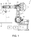
- the Fig. 1 Fig. 10 shows a welding robot as an example of a laser welding device arrangement.
- the welding robot comprises an industrial robot 1 with kinematics for movements in, for example, six degrees of freedom.
- the industrial robot 1 has, in a generally known manner, a robot arm 2 with joints, levers, in particular six axes A1 to A6, and a robot hand 4, at the end of which a fastening device designed as a flange 5 is arranged.
- the welding robot 1 comprises a laser welding device 9 which has a generally known laser welding head 7.
- the laser welding head 7 is attached to the flange 5 of the robot arm 2 and comprises focusing optics 8, from which a laser beam 11 emanates, by means of which a workpiece 20 can be provided with a weld seam 21.
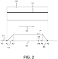
- a top view of the workpiece 20 with the weld seam 21 is shown in FIG Fig. 2 shown.
- the workpiece 20 comprises, for example, two partial workpieces that are to be welded together by means of the weld seam 21.
- the lever is moved relative to its axis A1 to A6 by a drive which, for example, each has an electric motor 3 and gear, as is generally known to the person skilled in the art.
- the industrial robot 1 also has a robot control device 10 which, in the case of the present exemplary embodiment, is designed as a control computer and is connected to the drives of the industrial robot 1 in a manner not shown and controls them by means of a computer program running on the robot control device 10, so that the robot arm 2 moves the laser welding head 7 on a desired path.
- the drives of the industrial robot 1 are in particular electric drives or regulated electric drives.
- the robot arm 2 generally represents a mechanical device for moving the laser welding head 7, which is controlled by means of the robot control device 10.
- the robot control device 10 can also be set up to control the laser welding device 9, in particular such that it controls the power of the laser beam 11 generated by the laser welding device 9 and provided for welding, and if necessary also regulates it.
- the welding device 9 comprises its own welding control device 12, which communicates with the robot control device 10.
- the welding control device 12 is set up, in particular, to control the laser welding head 7 in such a way that it generates a predetermined welding power P for welding the weld seam 21.
- the course of this welding power P along the weld seam 21 is location-dependent and in the Fig. 2 shown. If necessary, the laser control device 12 regulates the welding power.
- the Fig. 3 Fig. 13 is a flow chart illustrating the operation of the welding robot.
- the robot arm 2 controlled by its robot control device 10, moves the laser welding head 7 to a first position P2 relative to the workpiece 21, which is assigned to the start of the weld seam 21 to be produced, step B1 of in FIG Fig. 3 flowchart shown.
- the industrial robot 1 moves the laser welding head 7 in the direction of an arrow 22 at constant speed v to a second position P6 relative to the workpiece 21, which is assigned to the end of the weld seam 21 to be produced, step B2 of the Fig. 3 flowchart shown.
- the speed v is equal to the current speed at which the welding device 9 reaches the first position P2. During this movement, the workpiece 20 is provided with the weld seam 21.
- the laser welding head 7 Until the laser welding head 7 reaches the first position P2 assigned to the start of the weld 21 to be produced, the laser welding head 7 is switched off or is operated, controlled by the welding control device 12, with a very low welding power P, preferably close to zero watts or with no welding power at all.
- the welding power P of the laser welding head 7, controlled by the welding control device 12 is increased in a ramp-like manner, so that it has a predetermined power P at a position P3 relative to the weld 21 should be reached, step B3 of the Fig. 3 flowchart shown.
- the welding power P is increased continuously, for example.
- the position P3 relative to the weld seam 21 is specified so that the laser welding head 7 covers a specified first distance S2 between this position P3 and the first position P2 assigned to the start of the weld seam 21 to be produced.
- the welding control device 12 of the welding device 9 is designed in such a way that it moves the laser welding head 7 from the first position P2 associated with the start of the weld 21 to be produced to the position P3 on the basis of a first time period t 1 , within which the robot arm 2 moves at which the laser welding head 7 is to achieve the predetermined welding power P set , increased in a ramp-shaped manner.
- the welding control device 12 requires information about the first time period t 1 and when it begins.
- the welding control device 9 needs information about the predetermined welding power P soll .
- the specified welding power P should , for example, be permanently specified, in particular permanently stored in the welding control device 9, or, for example, also transmitted to the welding control device 9 by the robot control device 10, in particular when the laser welding head 7 is in the position assigned to the start of the weld 21 to be generated first P2 reached.
- the robot control device 10 transfers information about the first time period t 1 to the welding control device 12.
- the laser welding head 7 reaches a position P5 relative to the workpiece 20 during the welding of the weld seam 21, which is in front of the second position P6, which is assigned to the end of the weld seam 21 to be produced, then the welding power P of the laser welding head 7 becomes , controlled by the welding control device 12 in a ramp shape, in particular continuously, until it generates a very low welding power P , preferably close to zero watts, or no welding power at all, at the second position P6 assigned to the end of the weld 21 to be produced, step B4 of the in of the Fig. 3 flowchart shown. The welding process is then ended and the workpiece 20 is provided with the weld seam 21.
- the welding control device 12 of the welding device 9 is designed in such a way that it moves the laser welding head 7 from the position P5 to the second position P6 assigned to the end of the weld seam 21 on the basis of a second time period t 2 , within which the robot arm 2 moves the laser welding head 7, to decrease in a ramp.
- the welding control device 12 needs information about the second time period t 2 and when it begins.
- the robot control device 10 transfers information about the second time period t 2 to the welding control device 12.
- the two time periods t 1 , t 2 are calculated by the robot control device 10 and then transmitted to the welding control device 12 of the welding device 9 when the laser welding head 7 reaches the position P2 or P5.
- the two time periods t 1 , t 2 can be calculated using a subroutine or a function which is part of a computer program running on the robot control device 10, which can also be provided, for example, to control the robot arm 2.
- the first time period t 1 is calculated when the first position P2 is reached and transmitted to the welding control device 12, that is to say at the point in time at which the laser welding head 7 reaches the first position P2 assigned to the start of the weld 21 to be produced.
- the second time period t 2 is calculated when the position P5 is reached and transferred to the The welding control device 12 is transmitted, that is to say at the point in time at which the laser welding head 7 reaches the position P5, at which the welding power P should drop in a ramp-like manner.
- the running time of the function called up by the path switching function is not negligibly short, then in the case of the present exemplary embodiment it can be provided to calculate the function or the subroutine for calculating the first time period t 1 before reaching the first position P2 and to provide information to be transmitted to the welding control device 12 via the calculated first time period t 1 when the first position P2 is reached.
- the path switching function which the subroutine calls for calculating and forwarding the first time period t 1 , is called in particular before reaching the first position P2 so that all values are reliably available when the first position P2 is reached.
- the ramp-shaped increase in welding power P is started, in particular by setting an output of welding control device 12 by a computer program running on welding control device 12, i.e. welding power P of laser welding head 7 is increased.
- welding power P of laser welding head 7 is increased.
- this output is reset again.
- the function or the subroutine for calculating the first time period t 1 is called when the laser welding head 7 reaches a position P1, so that the laser welding head 7 still has to cover a distance S1 to get to the first one assigned to the start of the weld seam 21 to be produced To reach position P2.
- the function or the subroutine for calculating the second time period t 2 is calculated before the position P5 is reached and information about the second calculated time period t 2 is transmitted to the welding control device 12 when the position P5 is reached, i.e. at the point in time which the laser welding head 7 reaches the position P5 at which the welding power P is ramped should fall off.
- the path switching function, which the subroutine calls for calculating and forwarding the second time period t 2 is called in particular before the position P5 is reached so far that all values are reliably available when the position P5 is reached.
- the welding power P is reduced in a ramp-like manner, in particular by setting an output of the welding control device 12 by a computer program running on the welding control device 12. At the end of the welding process, i.e. when the welding power P is very small or zero, this output is reset again.
- the function or the subroutine for calculating the second time period t 2 is called when the laser welding head 7 reaches a position P4, so that the welding head 7 still has to cover a distance S4 in order to reach the position P5 at which the welding performance P should be reduced in a ramp. Distance S3 is covered between positions P3 and P4.
- the calculation of the ramp parameters can also be determined in any concurrent process.
- This process runs on the robot control device 10.
- the first time period t 1 is in particular calculated and passed on from the concurrent process so far before the first position P2 assigned to the start of the weld 21 to be produced is reached that all values at the time when the first position P2 is reached be available.
- the concurrent process is started when the laser welding head 7 reaches the position P1.
- the ramp is started in particular by setting an output of the welding control device 12 by a computer program running on the welding control device 12, i.e. the welding power P of the laser welding head 7 is increased in a ramp-like manner.
- the target welding power P target is reached, this output is reset again.
- the concurrent process for calculating the second time period t 2 is started before the position P5 is reached and information about the calculated second time period t 2 is transmitted to the welding control device 12 when the position P5 is reached, i.e. at the point in time when the laser welding head 7 reaches the position P5, at which the welding power P should decrease in a ramp-shaped manner.
- the concurrent process is started, for example, when the laser welding head 7 reaches position P4.
- the ramp-shaped increase in the welding power P can be designed in the form of a step.
- the ramp-shaped reduction in welding power P can also be designed in a stepped manner. If the cycle time or cycle time T cycle of the robot control device 10, which is designed as a control computer, is small enough, the ramp-shaped increase in the welding power P can be transmitted as setpoint values from the robot control device 10 to the welding control device 12 of the welding device 9, rising or falling in steps . In this case, the robot control device 10 in particular calculates the corresponding analog data in a secondary process and writes them to a corresponding output of the robot control device 10, which is connected to the welding control device 12 of the welding device 9.
- the robot control device 10 transfers discrete target values for the welding power that grow in the form of a staircase, which increase in the form of a ramp, or discrete target values for the welding power P that decrease in the form of a staircase and fall in the form of a ramp.
- the ramp is then not a straight line with a defined gradient, but has a step function.
- the laser welding head 7 is at least between the first position P2 and the second position P6 the constant speed v moves.
- n t 1 / T cycl
- the welding power P thus increases between the positions P2 and P3 from a minimum welding power P min , which the laser welding head 7 generates at the first position P2, to the target welding power P Soll when the position P3 is reached.
- the minimum welding power P min is preferably negligibly small or zero.
- ramp-shaped welding power P between positions P5 and P6 those for the welding control device 12 predetermined step-shaped target values of the welding power P are calculated accordingly.
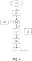
- the Fig. 4 illustrates, by means of a flow chart, the specification of the target values for the welding power P between the first position P2 and the position P3.
- the welding power P of the laser welding head 7 is equal to P min , step C1 of the flow chart of FIG Fig. 4 .
- a check is made as to whether the target value for the welding power P predetermined by the robot control device 10 is greater than or equal to the target welding power P Soll . This is queried in a step C3 of the flow chart. If this is the case, that the target welding power P target and thus the end of the ramp-shaped increase has been reached, step C4 of the flowchart of FIG Fig. 4 .
- the robot control device 10 waits for a period of time that is equal to half the cycle time Tcycl , step C5 of the flowchart of FIG Fig. 4 .
- the current setpoint value for the welding power P is transmitted from the robot control device 10 to the welding control device 12, step C6 of the flow chart in FIG Fig. 4 .
- the welding control device 12 controls the laser welding head 7 in such a way that it generates the current welding power to be generated. If necessary, the welding control device 12 regulates the laser welding head 7 accordingly.
- the target value of the new welding power which now represents the current target value of the welding power, is then compared again with the target welding power P target , step C2, flowchart of FIG Fig. 4 . Steps C2 to C8 of the flowchart of FIG Fig. 4 are repeated until the target value of the current new welding power is greater than or equal to the target welding power P Soll .
Landscapes
- Physics & Mathematics (AREA)
- Optics & Photonics (AREA)
- Engineering & Computer Science (AREA)
- Plasma & Fusion (AREA)
- Mechanical Engineering (AREA)
- Robotics (AREA)
- Laser Beam Processing (AREA)
- Manipulator (AREA)
Priority Applications (2)
| Application Number | Priority Date | Filing Date | Title |
|---|---|---|---|
| PL14812549T PL3086898T3 (pl) | 2013-12-23 | 2014-12-16 | Robot spawalniczy i sposób sterowania działaniem laserowego urządzenia spawalniczego |
| SI201431699T SI3086898T1 (sl) | 2013-12-23 | 2014-12-16 | Varilni robot in postopek za obratovanje naprave za lasersko varjenje |
Applications Claiming Priority (2)
| Application Number | Priority Date | Filing Date | Title |
|---|---|---|---|
| DE102013227148.4A DE102013227148A1 (de) | 2013-12-23 | 2013-12-23 | Schweißroboter und Verfahren zum Betreiben einer Laserschweißvorrichtung |
| PCT/EP2014/078099 WO2015097027A1 (de) | 2013-12-23 | 2014-12-16 | SCHWEIßROBOTER UND VERFAHREN ZUM BETREIBEN EINER LASERSCHWEIßVORRICHTUNG |
Publications (2)
| Publication Number | Publication Date |
|---|---|
| EP3086898A1 EP3086898A1 (de) | 2016-11-02 |
| EP3086898B1 true EP3086898B1 (de) | 2020-09-16 |
Family
ID=52102685
Family Applications (1)
| Application Number | Title | Priority Date | Filing Date |
|---|---|---|---|
| EP14812549.5A Active EP3086898B1 (de) | 2013-12-23 | 2014-12-16 | Schweissroboter und verfahren zum betreiben einer laserschweissvorrichtung |
Country Status (7)
| Country | Link |
|---|---|
| EP (1) | EP3086898B1 (pl) |
| DE (1) | DE102013227148A1 (pl) |
| ES (1) | ES2833130T3 (pl) |
| HU (1) | HUE051931T2 (pl) |
| PL (1) | PL3086898T3 (pl) |
| SI (1) | SI3086898T1 (pl) |
| WO (1) | WO2015097027A1 (pl) |
Families Citing this family (3)
| Publication number | Priority date | Publication date | Assignee | Title |
|---|---|---|---|---|
| CN106514068A (zh) * | 2016-11-15 | 2017-03-22 | 成都陵川特种工业有限责任公司 | 一种机器人智能焊接的控制方法 |
| CN111138076B (zh) * | 2019-12-30 | 2022-04-19 | 武汉华工激光工程有限责任公司 | 一种激光玻璃焊接控制系统及方法 |
| CN113954085A (zh) * | 2021-09-08 | 2022-01-21 | 重庆大学 | 一种基于双目视觉与线激光传感数据融合的焊接机器人智能定位与控制方法 |
Family Cites Families (11)
| Publication number | Priority date | Publication date | Assignee | Title |
|---|---|---|---|---|
| JPS63140788A (ja) * | 1986-12-03 | 1988-06-13 | Japan Nuclear Fuel Co Ltd<Jnf> | Co↓2レ−ザ溶接のクレ−タ処理方法 |
| JPH08257775A (ja) * | 1995-03-20 | 1996-10-08 | Nippon Steel Corp | 熱間圧延鋼片の接合方法 |
| DE19630521A1 (de) * | 1996-07-29 | 1998-02-05 | Juergen Schroeder | Verfahren zum nebenzeitlosen Laser-Schweißen von Werkstücken in einer Fertigungslinie und Vorrichtung zur Durchführung desselben |
| DE19750156A1 (de) * | 1997-11-12 | 1999-05-20 | K H Arnold Maschinenfabrik Gmb | Verfahren zur numerischen Steuerung einer Werkzeugmaschine mit variabler Strahlleistung zur Strahlbearbeitung und zugehörige Werkzeugmaschine |
| JP2003001452A (ja) * | 2001-06-15 | 2003-01-08 | Furukawa Electric Co Ltd:The | レーザ溶接方法およびその方法を用いて製造された半導体レーザモジュール |
| DE10229744A1 (de) * | 2002-07-03 | 2004-01-15 | Winter Pipeline Gmbh | Verfahren für fehlerfreies Laserschweißen im Start- /Stop-Bereich |
| DE10344526A1 (de) | 2003-09-24 | 2005-04-28 | Kuka Schweissanlagen Gmbh | Verfahren zum Laserstrahlschweißen von Bauteilen |
| JP5114874B2 (ja) * | 2005-09-30 | 2013-01-09 | 日産自動車株式会社 | レーザ溶接方法およびレーザ溶接装置 |
| DE102006030130B3 (de) * | 2006-06-28 | 2007-09-27 | Scansonic Gmbh | Verfahren und Vorrichtung zum Bearbeiten eines Werkstücks mittels eines Energiestrahls, insbesondere Laserstrahls |
| DE102008019636A1 (de) * | 2008-04-18 | 2009-10-22 | Fraunhofer-Gesellschaft zur Förderung der angewandten Forschung e.V. | Bauteil mit Schweißnaht und Verfahren zur Herstellung einer Schweißnaht |
| JP5460420B2 (ja) * | 2010-03-30 | 2014-04-02 | 三菱電機株式会社 | 加工制御装置およびレーザ加工装置 |
-
2013
- 2013-12-23 DE DE102013227148.4A patent/DE102013227148A1/de not_active Ceased
-
2014
- 2014-12-16 PL PL14812549T patent/PL3086898T3/pl unknown
- 2014-12-16 HU HUE14812549A patent/HUE051931T2/hu unknown
- 2014-12-16 WO PCT/EP2014/078099 patent/WO2015097027A1/de not_active Ceased
- 2014-12-16 SI SI201431699T patent/SI3086898T1/sl unknown
- 2014-12-16 ES ES14812549T patent/ES2833130T3/es active Active
- 2014-12-16 EP EP14812549.5A patent/EP3086898B1/de active Active
Non-Patent Citations (1)
| Title |
|---|
| None * |
Also Published As
| Publication number | Publication date |
|---|---|
| HUE051931T2 (hu) | 2021-04-28 |
| PL3086898T3 (pl) | 2021-04-06 |
| ES2833130T3 (es) | 2021-06-14 |
| SI3086898T1 (sl) | 2021-03-31 |
| DE102013227148A1 (de) | 2015-06-25 |
| EP3086898A1 (de) | 2016-11-02 |
| WO2015097027A1 (de) | 2015-07-02 |
Similar Documents
| Publication | Publication Date | Title |
|---|---|---|
| DE102018206077B4 (de) | Robotersteuerungsvorrichtung und Robotersteuerungsprogramm | |
| EP4046755B1 (de) | Vorrichtung und verfahren zum automatisierten entnehmen von in einem behälter angeordneten werkstücken | |
| DE102014108956A1 (de) | Vorrichtung zum Entgraten mit visuellem Sensor und Kraftsensor | |
| EP3849740B1 (de) | Verfahren und vorrichtung zum laserschneiden einer blechplatine aus einem kontinuierlich geförderten blechband | |
| EP0384925A1 (de) | Steuerungsverfahren bei einer numerischen Werkzeugmaschine oder einem Roboter | |
| DE10255037A1 (de) | Verfahren und Vorrichtung zum Bearbeiten eines Werkstücks | |
| EP2008753B1 (de) | Werkzeugmaschine und Verfahren zum Bearbeiten eines Werkstückes | |
| EP3112038A1 (de) | Verfahren zum reinigen einer innenwand eines rohres mit einer reinigungsvorrichtung, anbauvorrichtung zur aufnahme einer reinigungsvorrichtung für eine laserbearbeitungsmaschine sowie eine laserbearbeitungsmaschine | |
| EP3983168A1 (de) | Prozess zur strahlbearbeitung eines platten- oder rohrförmigen werkstücks | |
| EP3086898B1 (de) | Schweissroboter und verfahren zum betreiben einer laserschweissvorrichtung | |
| DE202007012687U1 (de) | Laserschweißvorrichtung | |
| EP3584041A1 (de) | Verfahren zum verbinden von bauteilen | |
| WO2002020213A2 (de) | Werkzeugmaschine mit kollisionsprüfung | |
| EP2130638A1 (de) | Verfahren zur Kantenbehandlung metallischer Werkstücke unter Verwendung eines Laserstrahles | |
| EP4114597A1 (de) | Verfahren zur additiven fertigung eines dreidimensionalen bauteils und system zur reparatur | |
| WO2023169751A1 (de) | Verfahren und system zum herstellen eines strukturbauteils | |
| DE102015002280B4 (de) | Verfahren und Anlage zum automatisierten Richten eines Gussteils | |
| DE202008003393U1 (de) | Modul zur Bearbeitung von Werkstücken | |
| EP3944911A1 (de) | System mit einer 3d-druckvorrichtung und verfahren zum betrieb eines solchen systems | |
| EP3411198B1 (de) | Roboteranlage | |
| EP3931648A2 (de) | Verfahren zur festlegung einer bewegungsbahn eines additiv oder subtraktiv wirkenden werkzeugs, verfahren zur abtragenden bearbeitung eines werkstücks mittels laserstrahl sowie anlage hierfür | |
| DE102015222942B4 (de) | Verfahren zum Bewegen eines Manipulators und Vorrichtung mit Manipulator | |
| EP3627258A1 (de) | Bewegungsplanung für eine servopresse | |
| EP3268172B1 (de) | Verfahren zur steuerung eines manipulators zur ausführung eines arbeitsprozesses | |
| WO2013124181A1 (de) | Verfahren und vorrichtung zum konditionieren von elektroden |
Legal Events
| Date | Code | Title | Description |
|---|---|---|---|
| PUAI | Public reference made under article 153(3) epc to a published international application that has entered the european phase |
Free format text: ORIGINAL CODE: 0009012 |
|
| 17P | Request for examination filed |
Effective date: 20160616 |
|
| AK | Designated contracting states |
Kind code of ref document: A1 Designated state(s): AL AT BE BG CH CY CZ DE DK EE ES FI FR GB GR HR HU IE IS IT LI LT LU LV MC MK MT NL NO PL PT RO RS SE SI SK SM TR |
|
| AX | Request for extension of the european patent |
Extension state: BA ME |
|
| DAX | Request for extension of the european patent (deleted) | ||
| STAA | Information on the status of an ep patent application or granted ep patent |
Free format text: STATUS: EXAMINATION IS IN PROGRESS |
|
| RAP1 | Party data changed (applicant data changed or rights of an application transferred) |
Owner name: KUKA DEUTSCHLAND GMBH |
|
| 17Q | First examination report despatched |
Effective date: 20180802 |
|
| GRAP | Despatch of communication of intention to grant a patent |
Free format text: ORIGINAL CODE: EPIDOSNIGR1 |
|
| STAA | Information on the status of an ep patent application or granted ep patent |
Free format text: STATUS: GRANT OF PATENT IS INTENDED |
|
| INTG | Intention to grant announced |
Effective date: 20200114 |
|
| GRAJ | Information related to disapproval of communication of intention to grant by the applicant or resumption of examination proceedings by the epo deleted |
Free format text: ORIGINAL CODE: EPIDOSDIGR1 |
|
| STAA | Information on the status of an ep patent application or granted ep patent |
Free format text: STATUS: EXAMINATION IS IN PROGRESS |
|
| INTC | Intention to grant announced (deleted) | ||
| GRAS | Grant fee paid |
Free format text: ORIGINAL CODE: EPIDOSNIGR3 |
|
| STAA | Information on the status of an ep patent application or granted ep patent |
Free format text: STATUS: GRANT OF PATENT IS INTENDED |
|
| GRAP | Despatch of communication of intention to grant a patent |
Free format text: ORIGINAL CODE: EPIDOSNIGR1 |
|
| GRAA | (expected) grant |
Free format text: ORIGINAL CODE: 0009210 |
|
| STAA | Information on the status of an ep patent application or granted ep patent |
Free format text: STATUS: THE PATENT HAS BEEN GRANTED |
|
| INTG | Intention to grant announced |
Effective date: 20200723 |
|
| AK | Designated contracting states |
Kind code of ref document: B1 Designated state(s): AL AT BE BG CH CY CZ DE DK EE ES FI FR GB GR HR HU IE IS IT LI LT LU LV MC MK MT NL NO PL PT RO RS SE SI SK SM TR |
|
| REG | Reference to a national code |
Ref country code: GB Ref legal event code: FG4D Free format text: NOT ENGLISH |
|
| REG | Reference to a national code |
Ref country code: CH Ref legal event code: EP |
|
| REG | Reference to a national code |
Ref country code: DE Ref legal event code: R096 Ref document number: 502014014773 Country of ref document: DE |
|
| REG | Reference to a national code |
Ref country code: IE Ref legal event code: FG4D Free format text: LANGUAGE OF EP DOCUMENT: GERMAN |
|
| REG | Reference to a national code |
Ref country code: AT Ref legal event code: REF Ref document number: 1313706 Country of ref document: AT Kind code of ref document: T Effective date: 20201015 |
|
| REG | Reference to a national code |
Ref country code: NL Ref legal event code: FP |
|
| REG | Reference to a national code |
Ref country code: SE Ref legal event code: TRGR |
|
| PG25 | Lapsed in a contracting state [announced via postgrant information from national office to epo] |
Ref country code: HR Free format text: LAPSE BECAUSE OF FAILURE TO SUBMIT A TRANSLATION OF THE DESCRIPTION OR TO PAY THE FEE WITHIN THE PRESCRIBED TIME-LIMIT Effective date: 20200916 Ref country code: GR Free format text: LAPSE BECAUSE OF FAILURE TO SUBMIT A TRANSLATION OF THE DESCRIPTION OR TO PAY THE FEE WITHIN THE PRESCRIBED TIME-LIMIT Effective date: 20201217 Ref country code: NO Free format text: LAPSE BECAUSE OF FAILURE TO SUBMIT A TRANSLATION OF THE DESCRIPTION OR TO PAY THE FEE WITHIN THE PRESCRIBED TIME-LIMIT Effective date: 20201216 Ref country code: BG Free format text: LAPSE BECAUSE OF FAILURE TO SUBMIT A TRANSLATION OF THE DESCRIPTION OR TO PAY THE FEE WITHIN THE PRESCRIBED TIME-LIMIT Effective date: 20201216 Ref country code: FI Free format text: LAPSE BECAUSE OF FAILURE TO SUBMIT A TRANSLATION OF THE DESCRIPTION OR TO PAY THE FEE WITHIN THE PRESCRIBED TIME-LIMIT Effective date: 20200916 |
|
| PG25 | Lapsed in a contracting state [announced via postgrant information from national office to epo] |
Ref country code: RS Free format text: LAPSE BECAUSE OF FAILURE TO SUBMIT A TRANSLATION OF THE DESCRIPTION OR TO PAY THE FEE WITHIN THE PRESCRIBED TIME-LIMIT Effective date: 20200916 Ref country code: LV Free format text: LAPSE BECAUSE OF FAILURE TO SUBMIT A TRANSLATION OF THE DESCRIPTION OR TO PAY THE FEE WITHIN THE PRESCRIBED TIME-LIMIT Effective date: 20200916 |
|
| REG | Reference to a national code |
Ref country code: LT Ref legal event code: MG4D |
|
| REG | Reference to a national code |
Ref country code: BE Ref legal event code: HC Free format text: DETAILS ASSIGNMENT: CHANGE OF OWNER(S), CHANGE OF OWNER(S) NAME Effective date: 20201021 |
|
| REG | Reference to a national code |
Ref country code: HU Ref legal event code: AG4A Ref document number: E051931 Country of ref document: HU |
|
| PG25 | Lapsed in a contracting state [announced via postgrant information from national office to epo] |
Ref country code: RO Free format text: LAPSE BECAUSE OF FAILURE TO SUBMIT A TRANSLATION OF THE DESCRIPTION OR TO PAY THE FEE WITHIN THE PRESCRIBED TIME-LIMIT Effective date: 20200916 Ref country code: SM Free format text: LAPSE BECAUSE OF FAILURE TO SUBMIT A TRANSLATION OF THE DESCRIPTION OR TO PAY THE FEE WITHIN THE PRESCRIBED TIME-LIMIT Effective date: 20200916 Ref country code: EE Free format text: LAPSE BECAUSE OF FAILURE TO SUBMIT A TRANSLATION OF THE DESCRIPTION OR TO PAY THE FEE WITHIN THE PRESCRIBED TIME-LIMIT Effective date: 20200916 Ref country code: LT Free format text: LAPSE BECAUSE OF FAILURE TO SUBMIT A TRANSLATION OF THE DESCRIPTION OR TO PAY THE FEE WITHIN THE PRESCRIBED TIME-LIMIT Effective date: 20200916 Ref country code: PT Free format text: LAPSE BECAUSE OF FAILURE TO SUBMIT A TRANSLATION OF THE DESCRIPTION OR TO PAY THE FEE WITHIN THE PRESCRIBED TIME-LIMIT Effective date: 20210118 |
|
| PG25 | Lapsed in a contracting state [announced via postgrant information from national office to epo] |
Ref country code: IS Free format text: LAPSE BECAUSE OF FAILURE TO SUBMIT A TRANSLATION OF THE DESCRIPTION OR TO PAY THE FEE WITHIN THE PRESCRIBED TIME-LIMIT Effective date: 20210116 Ref country code: AL Free format text: LAPSE BECAUSE OF FAILURE TO SUBMIT A TRANSLATION OF THE DESCRIPTION OR TO PAY THE FEE WITHIN THE PRESCRIBED TIME-LIMIT Effective date: 20200916 |
|
| REG | Reference to a national code |
Ref country code: ES Ref legal event code: FG2A Ref document number: 2833130 Country of ref document: ES Kind code of ref document: T3 Effective date: 20210614 |
|
| REG | Reference to a national code |
Ref country code: DE Ref legal event code: R097 Ref document number: 502014014773 Country of ref document: DE |
|
| PG25 | Lapsed in a contracting state [announced via postgrant information from national office to epo] |
Ref country code: SK Free format text: LAPSE BECAUSE OF FAILURE TO SUBMIT A TRANSLATION OF THE DESCRIPTION OR TO PAY THE FEE WITHIN THE PRESCRIBED TIME-LIMIT Effective date: 20200916 |
|
| PLBE | No opposition filed within time limit |
Free format text: ORIGINAL CODE: 0009261 |
|
| STAA | Information on the status of an ep patent application or granted ep patent |
Free format text: STATUS: NO OPPOSITION FILED WITHIN TIME LIMIT |
|
| REG | Reference to a national code |
Ref country code: CH Ref legal event code: PL |
|
| 26N | No opposition filed |
Effective date: 20210617 |
|
| PG25 | Lapsed in a contracting state [announced via postgrant information from national office to epo] |
Ref country code: DK Free format text: LAPSE BECAUSE OF FAILURE TO SUBMIT A TRANSLATION OF THE DESCRIPTION OR TO PAY THE FEE WITHIN THE PRESCRIBED TIME-LIMIT Effective date: 20200916 Ref country code: MC Free format text: LAPSE BECAUSE OF FAILURE TO SUBMIT A TRANSLATION OF THE DESCRIPTION OR TO PAY THE FEE WITHIN THE PRESCRIBED TIME-LIMIT Effective date: 20200916 |
|
| PG25 | Lapsed in a contracting state [announced via postgrant information from national office to epo] |
Ref country code: IE Free format text: LAPSE BECAUSE OF NON-PAYMENT OF DUE FEES Effective date: 20201216 Ref country code: LU Free format text: LAPSE BECAUSE OF NON-PAYMENT OF DUE FEES Effective date: 20201216 |
|
| PG25 | Lapsed in a contracting state [announced via postgrant information from national office to epo] |
Ref country code: LI Free format text: LAPSE BECAUSE OF NON-PAYMENT OF DUE FEES Effective date: 20201231 Ref country code: CH Free format text: LAPSE BECAUSE OF NON-PAYMENT OF DUE FEES Effective date: 20201231 |
|
| PG25 | Lapsed in a contracting state [announced via postgrant information from national office to epo] |
Ref country code: TR Free format text: LAPSE BECAUSE OF FAILURE TO SUBMIT A TRANSLATION OF THE DESCRIPTION OR TO PAY THE FEE WITHIN THE PRESCRIBED TIME-LIMIT Effective date: 20200916 Ref country code: MT Free format text: LAPSE BECAUSE OF FAILURE TO SUBMIT A TRANSLATION OF THE DESCRIPTION OR TO PAY THE FEE WITHIN THE PRESCRIBED TIME-LIMIT Effective date: 20200916 Ref country code: CY Free format text: LAPSE BECAUSE OF FAILURE TO SUBMIT A TRANSLATION OF THE DESCRIPTION OR TO PAY THE FEE WITHIN THE PRESCRIBED TIME-LIMIT Effective date: 20200916 |
|
| PG25 | Lapsed in a contracting state [announced via postgrant information from national office to epo] |
Ref country code: MK Free format text: LAPSE BECAUSE OF FAILURE TO SUBMIT A TRANSLATION OF THE DESCRIPTION OR TO PAY THE FEE WITHIN THE PRESCRIBED TIME-LIMIT Effective date: 20200916 |
|
| P01 | Opt-out of the competence of the unified patent court (upc) registered |
Effective date: 20230528 |
|
| PGFP | Annual fee paid to national office [announced via postgrant information from national office to epo] |
Ref country code: PL Payment date: 20250929 Year of fee payment: 12 |
|
| PGFP | Annual fee paid to national office [announced via postgrant information from national office to epo] |
Ref country code: NL Payment date: 20251003 Year of fee payment: 12 |
|
| PGFP | Annual fee paid to national office [announced via postgrant information from national office to epo] |
Ref country code: DE Payment date: 20250930 Year of fee payment: 12 |
|
| PGFP | Annual fee paid to national office [announced via postgrant information from national office to epo] |
Ref country code: GB Payment date: 20251001 Year of fee payment: 12 |
|
| PGFP | Annual fee paid to national office [announced via postgrant information from national office to epo] |
Ref country code: AT Payment date: 20251126 Year of fee payment: 12 |
|
| PGFP | Annual fee paid to national office [announced via postgrant information from national office to epo] |
Ref country code: IT Payment date: 20251121 Year of fee payment: 12 |
|
| PGFP | Annual fee paid to national office [announced via postgrant information from national office to epo] |
Ref country code: FR Payment date: 20251008 Year of fee payment: 12 Ref country code: HU Payment date: 20251112 Year of fee payment: 12 |
|
| PGFP | Annual fee paid to national office [announced via postgrant information from national office to epo] |
Ref country code: BE Payment date: 20251003 Year of fee payment: 12 |
|
| PGFP | Annual fee paid to national office [announced via postgrant information from national office to epo] |
Ref country code: SE Payment date: 20251001 Year of fee payment: 12 |
|
| PGFP | Annual fee paid to national office [announced via postgrant information from national office to epo] |
Ref country code: CZ Payment date: 20251203 Year of fee payment: 12 |
|
| PGFP | Annual fee paid to national office [announced via postgrant information from national office to epo] |
Ref country code: SI Payment date: 20251027 Year of fee payment: 12 |
|
| PGFP | Annual fee paid to national office [announced via postgrant information from national office to epo] |
Ref country code: ES Payment date: 20260113 Year of fee payment: 12 |