EP3086823B1 - Blood oxygenator - Google Patents
Blood oxygenator Download PDFInfo
- Publication number
- EP3086823B1 EP3086823B1 EP14874043.4A EP14874043A EP3086823B1 EP 3086823 B1 EP3086823 B1 EP 3086823B1 EP 14874043 A EP14874043 A EP 14874043A EP 3086823 B1 EP3086823 B1 EP 3086823B1
- Authority
- EP
- European Patent Office
- Prior art keywords
- blood
- oxygenator
- fiber bundle
- housing
- inlet
- Prior art date
- Legal status (The legal status is an assumption and is not a legal conclusion. Google has not performed a legal analysis and makes no representation as to the accuracy of the status listed.)
- Active
Links
- 210000004369 blood Anatomy 0.000 title claims description 174
- 239000008280 blood Substances 0.000 title claims description 174
- 239000000835 fiber Substances 0.000 claims description 101
- 230000017531 blood circulation Effects 0.000 claims description 35
- 238000004382 potting Methods 0.000 claims description 23
- 239000012530 fluid Substances 0.000 claims description 10
- 238000004891 communication Methods 0.000 claims description 8
- 230000001706 oxygenating effect Effects 0.000 claims description 3
- 230000003247 decreasing effect Effects 0.000 claims description 2
- 239000007789 gas Substances 0.000 description 48
- 239000012528 membrane Substances 0.000 description 29
- QVGXLLKOCUKJST-UHFFFAOYSA-N atomic oxygen Chemical compound [O] QVGXLLKOCUKJST-UHFFFAOYSA-N 0.000 description 21
- 229910052760 oxygen Inorganic materials 0.000 description 21
- 239000001301 oxygen Substances 0.000 description 21
- CURLTUGMZLYLDI-UHFFFAOYSA-N Carbon dioxide Chemical compound O=C=O CURLTUGMZLYLDI-UHFFFAOYSA-N 0.000 description 9
- 239000012510 hollow fiber Substances 0.000 description 9
- 230000002612 cardiopulmonary effect Effects 0.000 description 7
- 230000000241 respiratory effect Effects 0.000 description 6
- 238000012546 transfer Methods 0.000 description 6
- 229910002092 carbon dioxide Inorganic materials 0.000 description 5
- 238000013461 design Methods 0.000 description 5
- 238000000034 method Methods 0.000 description 5
- 230000008901 benefit Effects 0.000 description 4
- 239000001569 carbon dioxide Substances 0.000 description 4
- 230000007423 decrease Effects 0.000 description 4
- 238000009826 distribution Methods 0.000 description 4
- 238000006213 oxygenation reaction Methods 0.000 description 4
- 210000000601 blood cell Anatomy 0.000 description 3
- 239000000306 component Substances 0.000 description 3
- 238000010586 diagram Methods 0.000 description 3
- 238000009792 diffusion process Methods 0.000 description 3
- 230000007774 longterm Effects 0.000 description 3
- 206010058558 Hypoperfusion Diseases 0.000 description 2
- 230000015572 biosynthetic process Effects 0.000 description 2
- 230000000694 effects Effects 0.000 description 2
- 238000002618 extracorporeal membrane oxygenation Methods 0.000 description 2
- 238000001914 filtration Methods 0.000 description 2
- 238000004519 manufacturing process Methods 0.000 description 2
- 229920000642 polymer Polymers 0.000 description 2
- 230000037452 priming Effects 0.000 description 2
- 230000009467 reduction Effects 0.000 description 2
- 238000001356 surgical procedure Methods 0.000 description 2
- MYMOFIZGZYHOMD-UHFFFAOYSA-N Dioxygen Chemical compound O=O MYMOFIZGZYHOMD-UHFFFAOYSA-N 0.000 description 1
- JOYRKODLDBILNP-UHFFFAOYSA-N Ethyl urethane Chemical compound CCOC(N)=O JOYRKODLDBILNP-UHFFFAOYSA-N 0.000 description 1
- HTTJABKRGRZYRN-UHFFFAOYSA-N Heparin Chemical compound OC1C(NC(=O)C)C(O)OC(COS(O)(=O)=O)C1OC1C(OS(O)(=O)=O)C(O)C(OC2C(C(OS(O)(=O)=O)C(OC3C(C(O)C(O)C(O3)C(O)=O)OS(O)(=O)=O)C(CO)O2)NS(O)(=O)=O)C(C(O)=O)O1 HTTJABKRGRZYRN-UHFFFAOYSA-N 0.000 description 1
- 229920001247 Reticulated foam Polymers 0.000 description 1
- 208000007536 Thrombosis Diseases 0.000 description 1
- 208000027418 Wounds and injury Diseases 0.000 description 1
- 230000004913 activation Effects 0.000 description 1
- 230000002965 anti-thrombogenic effect Effects 0.000 description 1
- 238000013459 approach Methods 0.000 description 1
- 230000000712 assembly Effects 0.000 description 1
- 238000000429 assembly Methods 0.000 description 1
- 230000009286 beneficial effect Effects 0.000 description 1
- 239000012503 blood component Substances 0.000 description 1
- 238000013132 cardiothoracic surgery Methods 0.000 description 1
- 230000008859 change Effects 0.000 description 1
- 230000004087 circulation Effects 0.000 description 1
- 239000011248 coating agent Substances 0.000 description 1
- 238000000576 coating method Methods 0.000 description 1
- 238000000502 dialysis Methods 0.000 description 1
- 229910001882 dioxygen Inorganic materials 0.000 description 1
- 238000005516 engineering process Methods 0.000 description 1
- 210000003743 erythrocyte Anatomy 0.000 description 1
- 230000007717 exclusion Effects 0.000 description 1
- 238000000605 extraction Methods 0.000 description 1
- PCHJSUWPFVWCPO-UHFFFAOYSA-N gold Chemical compound [Au] PCHJSUWPFVWCPO-UHFFFAOYSA-N 0.000 description 1
- 238000010438 heat treatment Methods 0.000 description 1
- 229960002897 heparin Drugs 0.000 description 1
- 229920000669 heparin Polymers 0.000 description 1
- 208000014674 injury Diseases 0.000 description 1
- 230000010354 integration Effects 0.000 description 1
- 238000012423 maintenance Methods 0.000 description 1
- 239000000463 material Substances 0.000 description 1
- 230000007246 mechanism Effects 0.000 description 1
- 229910052751 metal Inorganic materials 0.000 description 1
- 239000002184 metal Substances 0.000 description 1
- 150000002739 metals Chemical class 0.000 description 1
- 238000002156 mixing Methods 0.000 description 1
- 238000012986 modification Methods 0.000 description 1
- 230000004048 modification Effects 0.000 description 1
- 239000013618 particulate matter Substances 0.000 description 1
- 239000011148 porous material Substances 0.000 description 1
- 238000005070 sampling Methods 0.000 description 1
- 229920006395 saturated elastomer Polymers 0.000 description 1
- 230000008733 trauma Effects 0.000 description 1
- 230000000472 traumatic effect Effects 0.000 description 1
- 239000011800 void material Substances 0.000 description 1
- XLYOFNOQVPJJNP-UHFFFAOYSA-N water Substances O XLYOFNOQVPJJNP-UHFFFAOYSA-N 0.000 description 1
Images


Classifications
-
- A—HUMAN NECESSITIES
- A61—MEDICAL OR VETERINARY SCIENCE; HYGIENE
- A61M—DEVICES FOR INTRODUCING MEDIA INTO, OR ONTO, THE BODY; DEVICES FOR TRANSDUCING BODY MEDIA OR FOR TAKING MEDIA FROM THE BODY; DEVICES FOR PRODUCING OR ENDING SLEEP OR STUPOR
- A61M1/00—Suction or pumping devices for medical purposes; Devices for carrying-off, for treatment of, or for carrying-over, body-liquids; Drainage systems
- A61M1/14—Dialysis systems; Artificial kidneys; Blood oxygenators ; Reciprocating systems for treatment of body fluids, e.g. single needle systems for hemofiltration or pheresis
- A61M1/16—Dialysis systems; Artificial kidneys; Blood oxygenators ; Reciprocating systems for treatment of body fluids, e.g. single needle systems for hemofiltration or pheresis with membranes
- A61M1/1698—Blood oxygenators with or without heat-exchangers
-
- A—HUMAN NECESSITIES
- A61—MEDICAL OR VETERINARY SCIENCE; HYGIENE
- A61M—DEVICES FOR INTRODUCING MEDIA INTO, OR ONTO, THE BODY; DEVICES FOR TRANSDUCING BODY MEDIA OR FOR TAKING MEDIA FROM THE BODY; DEVICES FOR PRODUCING OR ENDING SLEEP OR STUPOR
- A61M1/00—Suction or pumping devices for medical purposes; Devices for carrying-off, for treatment of, or for carrying-over, body-liquids; Drainage systems
- A61M1/14—Dialysis systems; Artificial kidneys; Blood oxygenators ; Reciprocating systems for treatment of body fluids, e.g. single needle systems for hemofiltration or pheresis
- A61M1/16—Dialysis systems; Artificial kidneys; Blood oxygenators ; Reciprocating systems for treatment of body fluids, e.g. single needle systems for hemofiltration or pheresis with membranes
- A61M1/1621—Constructional aspects thereof
- A61M1/1629—Constructional aspects thereof with integral heat exchanger
-
- A—HUMAN NECESSITIES
- A61—MEDICAL OR VETERINARY SCIENCE; HYGIENE
- A61M—DEVICES FOR INTRODUCING MEDIA INTO, OR ONTO, THE BODY; DEVICES FOR TRANSDUCING BODY MEDIA OR FOR TAKING MEDIA FROM THE BODY; DEVICES FOR PRODUCING OR ENDING SLEEP OR STUPOR
- A61M1/00—Suction or pumping devices for medical purposes; Devices for carrying-off, for treatment of, or for carrying-over, body-liquids; Drainage systems
- A61M1/36—Other treatment of blood in a by-pass of the natural circulatory system, e.g. temperature adaptation, irradiation ; Extra-corporeal blood circuits
- A61M1/3621—Extra-corporeal blood circuits
- A61M1/3623—Means for actively controlling temperature of blood
-
- A—HUMAN NECESSITIES
- A61—MEDICAL OR VETERINARY SCIENCE; HYGIENE
- A61M—DEVICES FOR INTRODUCING MEDIA INTO, OR ONTO, THE BODY; DEVICES FOR TRANSDUCING BODY MEDIA OR FOR TAKING MEDIA FROM THE BODY; DEVICES FOR PRODUCING OR ENDING SLEEP OR STUPOR
- A61M60/00—Blood pumps; Devices for mechanical circulatory actuation; Balloon pumps for circulatory assistance
- A61M60/10—Location thereof with respect to the patient's body
- A61M60/104—Extracorporeal pumps, i.e. the blood being pumped outside the patient's body
- A61M60/109—Extracorporeal pumps, i.e. the blood being pumped outside the patient's body incorporated within extracorporeal blood circuits or systems
- A61M60/113—Extracorporeal pumps, i.e. the blood being pumped outside the patient's body incorporated within extracorporeal blood circuits or systems in other functional devices, e.g. dialysers or heart-lung machines
-
- A—HUMAN NECESSITIES
- A61—MEDICAL OR VETERINARY SCIENCE; HYGIENE
- A61M—DEVICES FOR INTRODUCING MEDIA INTO, OR ONTO, THE BODY; DEVICES FOR TRANSDUCING BODY MEDIA OR FOR TAKING MEDIA FROM THE BODY; DEVICES FOR PRODUCING OR ENDING SLEEP OR STUPOR
- A61M60/00—Blood pumps; Devices for mechanical circulatory actuation; Balloon pumps for circulatory assistance
- A61M60/20—Type thereof
- A61M60/205—Non-positive displacement blood pumps
- A61M60/216—Non-positive displacement blood pumps including a rotating member acting on the blood, e.g. impeller
- A61M60/226—Non-positive displacement blood pumps including a rotating member acting on the blood, e.g. impeller the blood flow through the rotating member having mainly radial components
- A61M60/232—Centrifugal pumps
-
- A—HUMAN NECESSITIES
- A61—MEDICAL OR VETERINARY SCIENCE; HYGIENE
- A61M—DEVICES FOR INTRODUCING MEDIA INTO, OR ONTO, THE BODY; DEVICES FOR TRANSDUCING BODY MEDIA OR FOR TAKING MEDIA FROM THE BODY; DEVICES FOR PRODUCING OR ENDING SLEEP OR STUPOR
- A61M60/00—Blood pumps; Devices for mechanical circulatory actuation; Balloon pumps for circulatory assistance
- A61M60/30—Medical purposes thereof other than the enhancement of the cardiac output
- A61M60/36—Medical purposes thereof other than the enhancement of the cardiac output for specific blood treatment; for specific therapy
- A61M60/38—Blood oxygenation
-
- A—HUMAN NECESSITIES
- A61—MEDICAL OR VETERINARY SCIENCE; HYGIENE
- A61M—DEVICES FOR INTRODUCING MEDIA INTO, OR ONTO, THE BODY; DEVICES FOR TRANSDUCING BODY MEDIA OR FOR TAKING MEDIA FROM THE BODY; DEVICES FOR PRODUCING OR ENDING SLEEP OR STUPOR
- A61M2202/00—Special media to be introduced, removed or treated
- A61M2202/02—Gases
- A61M2202/0208—Oxygen
-
- A—HUMAN NECESSITIES
- A61—MEDICAL OR VETERINARY SCIENCE; HYGIENE
- A61M—DEVICES FOR INTRODUCING MEDIA INTO, OR ONTO, THE BODY; DEVICES FOR TRANSDUCING BODY MEDIA OR FOR TAKING MEDIA FROM THE BODY; DEVICES FOR PRODUCING OR ENDING SLEEP OR STUPOR
- A61M2205/00—General characteristics of the apparatus
- A61M2205/33—Controlling, regulating or measuring
- A61M2205/3331—Pressure; Flow
- A61M2205/3334—Measuring or controlling the flow rate
-
- A—HUMAN NECESSITIES
- A61—MEDICAL OR VETERINARY SCIENCE; HYGIENE
- A61M—DEVICES FOR INTRODUCING MEDIA INTO, OR ONTO, THE BODY; DEVICES FOR TRANSDUCING BODY MEDIA OR FOR TAKING MEDIA FROM THE BODY; DEVICES FOR PRODUCING OR ENDING SLEEP OR STUPOR
- A61M2205/00—General characteristics of the apparatus
- A61M2205/33—Controlling, regulating or measuring
- A61M2205/3368—Temperature
-
- A—HUMAN NECESSITIES
- A61—MEDICAL OR VETERINARY SCIENCE; HYGIENE
- A61M—DEVICES FOR INTRODUCING MEDIA INTO, OR ONTO, THE BODY; DEVICES FOR TRANSDUCING BODY MEDIA OR FOR TAKING MEDIA FROM THE BODY; DEVICES FOR PRODUCING OR ENDING SLEEP OR STUPOR
- A61M2205/00—General characteristics of the apparatus
- A61M2205/36—General characteristics of the apparatus related to heating or cooling
- A61M2205/366—General characteristics of the apparatus related to heating or cooling by liquid heat exchangers
-
- A—HUMAN NECESSITIES
- A61—MEDICAL OR VETERINARY SCIENCE; HYGIENE
- A61M—DEVICES FOR INTRODUCING MEDIA INTO, OR ONTO, THE BODY; DEVICES FOR TRANSDUCING BODY MEDIA OR FOR TAKING MEDIA FROM THE BODY; DEVICES FOR PRODUCING OR ENDING SLEEP OR STUPOR
- A61M2206/00—Characteristics of a physical parameter; associated device therefor
- A61M2206/10—Flow characteristics
- A61M2206/16—Rotating swirling helical flow, e.g. by tangential inflows
-
- A—HUMAN NECESSITIES
- A61—MEDICAL OR VETERINARY SCIENCE; HYGIENE
- A61M—DEVICES FOR INTRODUCING MEDIA INTO, OR ONTO, THE BODY; DEVICES FOR TRANSDUCING BODY MEDIA OR FOR TAKING MEDIA FROM THE BODY; DEVICES FOR PRODUCING OR ENDING SLEEP OR STUPOR
- A61M2209/00—Ancillary equipment
- A61M2209/08—Supports for equipment
- A61M2209/088—Supports for equipment on the body
Definitions
- Present disclosure relates generally to blood oxygenator devices and methods of their use, and more particularly to blood oxygenators that provide uniform flow and oxygenation.
- Hollow fiber membrane blood oxygenators are the current gold standard for blood oxygenation. These oxygenators typically incorporate one of four blood flow path configurations, as summarized in U.S. Patent No. 5,462,619 : (1) longitudinal (axial) flow through an annular bundle (see U.S. Patent No. 4,975,247 ); (2) circumferential flow around an annular bundle (see U.S. Patent No. 3,794,468 ); (3) transverse flow across a bundle of substantially rectangular cross-section (see U.S. Patent No. 5,188,801 ); and (4) radially outward flow through an annular bundle (see U.S. Patent No. 3,422,008 ).
- U.S. Patent No. 5,462,619 (1) longitudinal (axial) flow through an annular bundle (see U.S. Patent No. 4,975,247 ); (2) circumferential flow around an annular bundle (see U.S. Patent No. 3,794,468 ); (3) transverse flow across a bundle of substantially rectangular cross-section (see U.S. Patent No. 5,188,
- the membrane blood oxygenators based on the above principles are generally acceptable for cardiopulmonary bypass during open heart surgeries, they have a number of problems when they are used for respiratory support over longer durations (e.g., days to weeks). They have a relatively large blood-contacting surface area, a large prime volume, and a large physical size with very limited long-term biocompatibility and durability.
- the drawbacks of these oxygenators are associated with inherent blood fluid dynamics within these oxygenators, including non-uniform blood flow through the fiber membranes, the existence of laminar boundary flow zones between the blood cells and fiber membranes, and large physical size.
- the non-uniform blood flow across the fiber membranes results in hyper- and hypo-perfusion of blood in the flow path.
- Hyper-perfusion does not have any additional benefit once blood is oxygen-saturated.
- longer flow paths are needed, thus resulting in extended blood contact with the fiber membrane surfaces and a large surface area of the fiber membranes.
- a relatively thick blood boundary layer is developed.
- the blood boundary layer that is formed increases the resistance to oxygen diffusion to blood cells that are not directly in contact with the fiber membrane surface.
- the gas transfer efficiency can be significantly hindered by the existence of the boundary layer. Therefore, gas exchange membrane surface areas of 2 to 4 m 2 and a large prime volume are typically required to provide the needed gas exchange.
- the non-uniform blood flow can potentially induce excessive mechanical shear stresses or stasis in the blood flow path in the oxygenators. These are the major contributing factors to blood activation and thrombosis formation, resulting in limited long-term biocompatibility and durability. In addition, the large physical size also limits the wearability for ambulatory respiratory support.
- Mathewson describes the integrated centrifugal pump and membrane oxygenator in which the hollow fibers are displaced circumferentially in a ring around an impeller of the centrifugal pump. The blood is pumped through the hollow fibers for oxygenation.
- One drawback of Mathewson's design is that there exist potential stagnant flow zones between the annular fiber bundle and the outer housing wall.
- a rotating impeller was introduced to generate uniform blood flow through an annular fiber bundle, as described in U.S. Patent No. 8,496,874 .
- the use of an integrated rotating impeller to achieve uniform blood flow may be beneficial.
- integration of the pump with a blood oxygenator into a system can introduce difficulties for manufacturing and complex flow paths in the integrated system.
- a blood oxygenator according to the invention is defined in claim 1.
- a system for oxygenating blood according to the invention is defined in claim 15.
- Disclosed is a unique blood oxygenator that addresses one or more of the shortcomings of the prior art. More particularly, a blood oxygenator is provided herein having unique blood flow distribution control, resulting in a significant reduction of membrane surface area and priming volume, and reduced trauma when compared with currently known oxygenator technologies. Techniques are also provided for a blood oxygenator device that provides one or more advantages over currently available blood oxygenators. In various embodiments, the device provides long-term durability and reliability, and can be used for, among other applications, cardiopulmonary bypass during cardiothoracic surgeries, extracorporeal membrane oxygenation (ECMO) for cardiopulmonary support or respiratory support in hospitals, and ambulatory ECMO.
- ECMO extracorporeal membrane oxygenation
- a blood oxygenator includes a housing, a blood inlet, a blood outlet, a spiral volute, a gas inlet, an oxygenator fiber bundle, and a gas outlet.
- the housing encloses the fiber bundle and provides the structure for the blood flow path and connectors.
- the fiber bundle comprises gas-exchange membranes that transfer oxygen to the blood and remove carbon dioxide when the blood flows across the membranes.
- the spiral volute guides the blood to flow through the fiber bundle.
- the gas flow chamber receives sweep gas containing oxygen and distributes the sweep gas into the fiber membranes.
- a heat exchanger is integrated into the blood oxygenator.
- the heat exchange element is located between an annular space and the fiber bundle.
- kits that includes both a blood oxygenator and a blood pump.
- the kit may be specifically configured for ambulatory cardiopulmonary and respiratory support.
- a device, system, and method are described herein for a blood oxygenator.
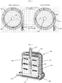
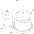
- the exterior of a blood oxygenator 100 comprises a housing 110 having a top 105 and a bottom 107.
- the top 105 of the housing 110 has a blood outlet 125.
- the top 105 of the housing includes a gas exhaust port 135 and, in some instances, may include a vent port 137 on housing 110 (shown on Figure 2 ).
- the bottom 107 of the housing 110 has a blood inlet 120 and, in some exemplary embodiments, a gas inlet 130.
- the housing 110 encloses the internal elements of blood oxygenator 100, as depicted in Figure 2 , including the oxygenator fiber bundle 150, and provides the structure for the blood flow path and connectors.
- the blood inlet 120 on the bottom 107 of the housing 110 is connected to a spiral volute 140.
- the phrase "spiral volute” refers to a spiral or helical flow path formed in a cylindrical annulus between the outer, typically cylindrical, surface of the fiber bundle and an inner surface of the housing.
- the cross-sectional area of the flow path will generally be at a maximum at an inlet end of the flow path, and will decrease toward the outlet end in order to at least partially offset the reduction in flow velocity that would otherwise occur as the blood flows from the flow path into the fiber bundle.
- the spiral volute 140 has a first end 141 (shown in the lower elevation of Figure 3 ) and a second end 142 (shown in the higher elevation of Figure 3 ).
- the blood inlet 120 connects with the spiral volute 140 at the first end 141.
- the channel extending between first end 141 and second end 142 of the spiral volute 140 defines an internal cavity 143 that decreases in size from the first end 141 to the second end 142. As shown in Figure 3 , as the internal cavity 143 of spiral volute 140 decreases in size, it also moves up in elevation in a spiral formation.
- the spiral volute 140 has an aperture 144 that connects the internal cavity 143 to an annular space 145 between an inner wall 113 of housing 110 and an outer surface 147 of an oxygenator fiber bundle 150 in blood oxygenator 100, as shown in Figures 2 and 4 .
- the aperture 144 allows blood to enter the annular space 145 from the internal cavity 143.
- a uniform blood flow path across the membranes in the fiber bundle 150 is achieved by the spiral volute 140.
- the blood is guided by the blood inlet 120 into the spiral volute 140 which gradually discharges the blood circumferentially (360 degree) into the annular space 145 between the inner wall 113 of the housing 110 and outer surface 147 of fiber bundle 150.
- Annular space 145 is generally in the shape of a cylinder, the outer perimeter of which preferably conically tapers inward as the annular space 145 extends away from spiral volute 140.
- Spiral volute 140 extends circumferentially around the interior of housing 110 and has a gradually decreasing radius as it extends spirally upwards.
- the aperture 144 of the spiral volute 140 that opens into the cylindrical annular space 145 is progressively increased and finally merges into the annular space 145. Further, the aperture 144 of the spiral volute 140 preferably merges into the annual space about 300° from the first end 141; i.e., the second end 142 is at a position 300° from the first end 141.
- Fiber bundle 150 preferably comprises a cylindrical annulus composed of thousands of microporous hollow fibers with pore sizes of less than 0.1 micron.
- the membrane fibers are commercially available and range in size from 250 to 400 micron outside diameter with a wall thickness of approximately 30 to 50 microns thick.
- the fiber membranes may or may not include an anti-thrombogenic coating containing heparin or a functional equivalent attached to the outside of each fiber.
- the porosity (void ratio) of the fiber bundle 150 is determined according to the desired pressure loss across the fiber bundle, typically ranging from 0.4 to 0.7.
- coated or skinned hollow fibers may be utilized, which permit oxygen and carbon dioxide diffusion through a non-porous skin layer of the outer wall of the fibers.
- the fibers are typically commercially available in a tape configuration whereby individual fibers are arranged to a predetermined configuration (e.g., parallel straight or bias, multi-directional, woven, spaced, etc.) permitting tape wrapping to form a cylindrical or conical-like bundle configuration.
- a predetermined configuration e.g., parallel straight or bias, multi-directional, woven, spaced, etc.
- the fiber can be wrapped or wound like a spool of kite-string.
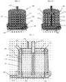
- the ends of the fiber bundle 150 are cast potted in a polymer (e.g., urethane) to form upper potting 154 and lower potting 152.
- the bundle ends are trimmed at upper potting 154 and lower potting 152 to open the internal passages of the hollow fibers. It is through these inner lumens that the sweep gas is distributed.
- the fiber bundle 150 is affixed onto the housing at the lower potting 152 and upper potting 154.
- the blood and gas are structurally separated by the lower potting 152 and the upper potting 154.
- the fiber bundle 150 is configured to allow blood to move from the outer surface 147 of fiber bundle 150 through the internal passages of the hollow fibers into a central lumen 160.
- the central lumen 160 is configured to receive blood that travels through fiber bundle.
- the upper end of lumen 160 communicates with blood outlet 125.
- blood travels from the outer surface 147 of the oxygenator fiber bundle 150 through the oxygenator fiber bundle 150, into the central lumen 160, and out of the housing 110 through the blood outlet 125.
- Guide structure 162 may optionally be provided within central lumen 160 to help channel the blood out of the blood oxygenator 100.
- the guide structure 162 extends orthogonally from the bottom 107 of housing 110.
- Gas inlet 130 is preferably located in bottom 107 of housing 110. Gas inlet 130 communicates with lower gas flow chamber 132 which allows for the distribution of the gas into the fiber membranes of the fiber bundle 150. An upper gas flow chamber 134 located on the top 105 of the housing 110 receives the expelled gas from the fiber membranes and allows for the gas to exit gas exhaust port 135.
- Blood oxygenator 100 preferably also includes a vent port 137, as shown in Figure 2 , positioned within housing 110 at the location at which air bubbles are likely to accumulate. It is important to be able to remove gaseous bubbles from the blood oxygenator 100 during use. Bubbles typically result from trapped air failing to adequately de-bubble during priming, broken membrane fibers, or excessive negative pressure applied to the blood drawing gas out of solution.
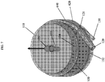
- Figure 5a provides a transparent view of the blood oxygenator showing the above components in a fully assembled blood oxygenator 100.
- Figure 5b shows the same transparent view, and also shows a schematic representation of a blood flow path through blood oxygenator 100. More particularly, first segment 170 shows the path in which blood enters blood oxygenator 100, from which it travels into the spiral volute along spiral flow path segment 171. From the start of opening 144 to the end of spiral volute 140, blood likewise flows upward in the direction of flow lines 172 from spiral volute 140 and into annular space 145 in a continuous, vertical flow path extending circumferentially around fiber bundle 150. As blood flows upward in the direction of flog lines 172, it likewise flow radially inward in the direction of flow lines 173 and toward central lumen 160, and then upward through central lumen 160 and out through blood outlet 125.
- Blood oxygenator 100 may also optionally provide a heat exchange function.
- an optional heat exchange element 180 is provided in the form of a cylindrical annulus around the fiber bundle 150.
- the heat exchange element 180 is located between the outer surface 147 of the fiber bundle 150 and the annular space 145.
- the heat exchange element may be comprised of capillaries formed together to construct a cylindrical annulus, and potted together with the fiber bundle.
- the heat exchange element capillaries can either be made of biocompatible metals or polymers. After being potted, the lumen of the capillaries can be opened using the same approach as for the hollow fibers of fiber bundle 150. A separate flow path through the heat exchange element capillaries is provided.
- enclosed chambers are disposed in the housing above the upper potting 154 and below the lower potting 152.
- a first chamber 134 is provided above the upper potting 154 for the sweep gas and is in fluid communication with exit gas exhaust port 135, while a second chamber 534 is provided above the upper potting 154 and is in fluid communication with exhaust port 535 for the heat transfer medium.
- a first chamber 132 is again provided below the lower potting 152 for the sweep gas and is in fluid communication with gas inlet 130 (not shown in Figure 5 ), while a second chamber 532 is provided below lower potting 152 and is in fluid communication with an inlet 530 for supply of the heat transfer medium.
- the blood is heated and controlled for temperature, the oxygen is transferred to the blood, and carbon dioxide is removed from the blood while the blood radially flows through the heat exchange element 180 and the fiber bundle 150.
- Other means for heating the blood may also be used without departing from the spirit or scope of the invention.
- a portion of the oxygen fibers may be substituted with fibers that enable heat exchange.
- Such a configuration would also utilize hollow tube(s), the inside of which could flow temperature controlled water or other fluid to affect blood temperature change and/or maintenance.
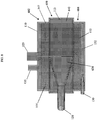
- housing 110 may include a top housing section 602, a bottom housing section 604, and a mid-housing section 610. While each of such housing sections are generally cylindrical in form, top housing section 602 and bottom housing section 604 preferably have the same diameter, and moreover are configured alike to the corresponding portions of housing 110 shown in Figure 2 , while mid-housing section 610 has a wider diameter so as to incorporate spiral volute 640.
- Bottom housing section 604 includes gas inlet 130 configured as described above, with first chamber 132 in communication with gas inlet 130 to receive the sweep gas.
- fiber bundle 150 is provided inside of housing 110, and is positioned so that lower potting section 152 of fiber bundle 150 is positioned within bottom housing section 604, upper potting section 154 of fiber bundle 150 is positioned within top housing section 602, and the central gas exchange portion of fiber bundle 150 is positioned within mid-housing section 610.
- Top housing section 602 also includes gas exhaust port 135 configured as described above, and blood outlet 125 configured as described above and in communication with an internal, central lumen 160 which may optionally include a guide structure 162, again all configured as described above.
- the spiral volute 640 is positioned in the space between the outer surface 147 of fiber bundle 150 and the inner wall 113 of housing 110.
- circular blood inlet 120 is positioned in the middle of mid-housing section 610.
- the blood flow bath begins to vertically widen, expanding into the full vertical height of spiral volute 140 (generally equal in dimension to the radially absorptive portion of fiber bundle 150) through a transitional area 620.
- transitional area 620 vertically expands the blood flow path, it likewise progressively narrows that flow path by narrowing the gap between the outer surface 147 of the fiber bundle 150 and the inner wall 113 of housing 110, as best shown in the top-down, sectional view of Figure 9 .
- the inner wall 113 of housing 110 is nearly contiguous with the outer surface 147 of fiber bundle 150.
- blood entering through blood inlet 120 and passing therefrom into transitional area 620 diverges as it passes through transitional area 620, and from transitional area 620 enters into the spiral volute 640 to begin circulation around fiber bundle 150.
- the blood oxygenator 100 may be connected to a blood pump 230.
- Pump 230 is connected to the blood inlet of blood oxygenator 100, such as through a quick connector 190 of standard configuration.
- pump 230 and blood oxygenator 100 may be provided together as a kit. It is contemplated that the kit may comprise the various elements required for the blood oxygenator 100 to function. Such kits may be particularly useful for ambulatory cardiopulmonary and respiratory support.
- blood pump 230 and blood oxygenator 100 can both be contained within housing 110 in a single unit.
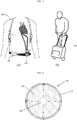
- Blood oxygenator 100 may likewise be connected to a portable oxygen tank and worn on the user, as depicted in Figure 12(a) .
- Figure 12(a) straps 708 of a portable oxygen tank are shown, in which case the portable oxygen tank may be positioned on the user's back.
- the oxygen tank is connected to blood oxygenator 100.
- blood oxygenator 100 and the oxygen tank may be placed inside a cart or bag 740 that the user can manage as shown in Figure 12(b) .
- an oxygen concentrator 730 may be positioned to receive oxygen from the portable oxygen tank and to deliver it to blood oxygenator 100.
- the oxygen concentrator 730 converts air into high oxygen concentration (>90%) gas.
- a portable drive console may be provided that can optionally enclose each of the oxygen concentrator 730, a battery power pack, and electronics for the blood pump, flow sensors and blood gas sensors. Kits may be provided that comprise two or more of the components described above.
- Blood oxygenator 100 may also optionally include arterial and venous sample ports (not shown) permitting blood samples to be collected by a syringe, such as (by way of nonlimiting example) traditional stopcocks or obturator-type sample ports.
- the sampling ports should provide for the extraction of whole blood from sites before and after the fiber bundle 150 to enable the user to adjust blood flow rates, gas transfer rates and pH for control of oxygen concentration.
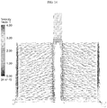
- the design of the blood oxygenator 100 as configured herein optimizes blood flow. Many of the elements of blood oxygenator 100 that transport patient blood are generally cylindrical or round to promote even flow and reduce turbulence and stagnation. Blood enters the blood inlet 120 with tangential blood velocity relative to the outer surface of the fiber bundle 150. A portion of the blood volume continues to flow in the volute with mainly circumferential velocity, and a portion of the blood volume gradually leaves the volute to enter the annular space 145 with spiral-circumferential velocity.
- This blood flow discharge mechanism provides a circumferential flow field around the fiber bundle 150 with equal pressure distribution prior to entering the fiber bundle by the spiral volute 140. With this equal pressure distribution, blood radially flows inward through the fiber membranes in the fiber bundle 150.
- the design of blood oxygenator 100 also allows for optimized gas flow and diffusion.
- the lower gas flow chamber 132 receives the sweep gas from the gas inlet 130 and distributes oxygen gas to the open lumen fibers imbedded in potting material (and particularly lower potting 152) of the fiber bundle 150.
- the oxygen flows through the lumen and diffuses across the outer wall of the individual fiber membranes into the blood, thus allowing blood oxygenation to take place.
- the carbon dioxide from the blood diffuses into the lumen of the fiber membranes and is removed from the blood.
- the sweep gas flows through the fiber and exits the blood oxygenator 100 through the gas exhaust port 135 in the upper flow chamber 134 of the housing 110 above the upper potting 154.
- the lower gas flow chamber 132 ensures that a low pressure and uniform sweep gas is established in all the fibers simultaneously.
- the gas inlet 130 receives the sweep gas to deliver the sweep gas to the interior of blood oxygenator 100.
- the blood inflow and outflow connectors may be sized as required for desired blood flow rates and pressures. Typically, such devices are fitted with 1 ⁇ 4" or 3/8" barbed fittings receiving standard extracorporeal tubing, although other sizes may be used.
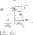
- Figure 15 provides a block diagram depicting one exemplary setup using the blood oxygenator 100.
- Blood is taken from a patient through drainage cannula 210 and enters into reservoir 220.
- Blood pump 230 forces blood from the reservoir 220, into blood oxygenator 100 (configured as described above), and back to the patient through return cannula 215.
- a gas/oxygen source 240 communicates with the blood oxygenator 100 to provide oxygen.
- a water-heat circulator 250 preferably also communicates with blood oxygenator 100 in those configurations that employ a heat exchange function.
- Sensors may be used to retrieve information about the blood, such as blood gas concentration sensors 261, blood flow rate sensors 262, and blood temperature sensors 263.
- Embodiments may include microporous membranes to filter blood components as utilized in blood dialysis. Further, embodiments may include a filter (e.g., depth filter, reticulated foam, microporous filtration, filtration mediums, etc.) to capture particulate matter as a fluid is driven through the filter.
- a filter e.g., depth filter, reticulated foam, microporous filtration, filtration mediums, etc.
- the blood oxygenator 100 disclosed herein has improved manufacturability over other similar designs of blood oxygenators. It includes fewer components than other blood oxygenating devices. Further, the joints and bonding area may be easily accessed, which makes the blood oxygenator 100 easier, cheaper and more reliable to manufacture.
Landscapes
- Health & Medical Sciences (AREA)
- Heart & Thoracic Surgery (AREA)
- Engineering & Computer Science (AREA)
- Cardiology (AREA)
- Hematology (AREA)
- Public Health (AREA)
- Anesthesiology (AREA)
- Biomedical Technology (AREA)
- Veterinary Medicine (AREA)
- Life Sciences & Earth Sciences (AREA)
- Animal Behavior & Ethology (AREA)
- General Health & Medical Sciences (AREA)
- Emergency Medicine (AREA)
- Vascular Medicine (AREA)
- Urology & Nephrology (AREA)
- Mechanical Engineering (AREA)
- Pulmonology (AREA)
- External Artificial Organs (AREA)
- Separation Using Semi-Permeable Membranes (AREA)
Applications Claiming Priority (2)
| Application Number | Priority Date | Filing Date | Title |
|---|---|---|---|
| US201361919837P | 2013-12-23 | 2013-12-23 | |
| PCT/US2014/072046 WO2015100288A1 (en) | 2013-12-23 | 2014-12-23 | Blood oxygenator |
Publications (3)
| Publication Number | Publication Date |
|---|---|
| EP3086823A1 EP3086823A1 (en) | 2016-11-02 |
| EP3086823A4 EP3086823A4 (en) | 2017-07-05 |
| EP3086823B1 true EP3086823B1 (en) | 2018-11-21 |
Family
ID=53479637
Family Applications (1)
| Application Number | Title | Priority Date | Filing Date |
|---|---|---|---|
| EP14874043.4A Active EP3086823B1 (en) | 2013-12-23 | 2014-12-23 | Blood oxygenator |
Country Status (5)
| Country | Link |
|---|---|
| US (3) | US10188780B2 (ja) |
| EP (1) | EP3086823B1 (ja) |
| JP (1) | JP6461975B2 (ja) |
| CN (1) | CN105828848B (ja) |
| WO (1) | WO2015100288A1 (ja) |
Families Citing this family (38)
| Publication number | Priority date | Publication date | Assignee | Title |
|---|---|---|---|---|
| WO2015100288A1 (en) * | 2013-12-23 | 2015-07-02 | University Of Maryland, Baltimore | Blood oxygenator |
| EP3129080B1 (en) * | 2014-04-07 | 2019-05-22 | Carnegie Mellon University | Compact pulmonary assist device for destination therapy |
| US20180001012A1 (en) * | 2014-12-16 | 2018-01-04 | The Regents Of The University Of California | Portable Lung Assist Device |
| CA2988997C (en) * | 2015-06-23 | 2024-04-09 | University Of Pittsburgh - Of The Commonwealth System Of Higher Education | Extracorporeal ambulatory assist lung |
| EP3574935B1 (de) * | 2015-06-29 | 2020-12-16 | novalung GmbH | Tragevorrichtung für eine gasaustauschvorrichtung |
| DE102016002950A1 (de) * | 2016-03-11 | 2017-09-14 | Rheinisch-Westfälische Technische Hochschule (Rwth) Aachen | System zu extrakorporalen Elimination von Kohlenmonoxid |
| CN109195645B (zh) * | 2016-08-31 | 2021-12-21 | 泰尔茂株式会社 | 换热器、人工肺及换热器的制造方法 |
| IT201700032687A1 (it) * | 2017-03-24 | 2018-09-24 | Qura S R L | Un ossigenatore di fluidi organici |
| US10765969B2 (en) | 2017-07-25 | 2020-09-08 | Hamilton Sundstrand Corporation | Fluid degassing systems |
| EP3668556A4 (en) * | 2017-08-15 | 2021-06-23 | University of Maryland, Baltimore | TWO-CHAMBER GAS EXCHANGER AND METHOD OF USING BREATHING ASSISTANCE |
| IT201700111990A1 (it) | 2017-10-05 | 2019-04-05 | Spectrum Medical Group Ltd | Scambiatore per uso medicale |
| US20200397966A1 (en) * | 2018-02-26 | 2020-12-24 | Hemovent Gmbh | Holding Means for Holding an Oxygenator and a Blood Pump |
| US11529508B2 (en) * | 2018-03-02 | 2022-12-20 | Tc1 Llc | Wearable accessory for ventricular assist system |
| WO2019198091A1 (en) * | 2018-04-12 | 2019-10-17 | Yeda Research And Development Co. Ltd. | Blood based treatment |
| RU190014U1 (ru) * | 2018-07-24 | 2019-06-14 | Александр Иванович Андреев | Мембранный оксигенатор |
| CN109364367B (zh) * | 2018-09-28 | 2021-01-01 | 东莞科威医疗器械有限公司 | 一种流量控制阀及离心注料装置 |
| CN109224163B (zh) * | 2018-10-16 | 2019-06-21 | 广东工业大学 | 一种热交换层外置的中空纤维膜式氧合器 |
| CN109224165A (zh) * | 2018-11-27 | 2019-01-18 | 江苏美思康医疗科技有限公司 | 一种带变温的集成离心泵的膜式氧合器 |
| CN109364315A (zh) * | 2018-12-07 | 2019-02-22 | 江苏美思康医疗科技有限公司 | 一种带变温双腔膜式氧合器 |
| CN109481769B (zh) * | 2018-12-11 | 2019-11-12 | 广东工业大学 | 一种带生物相容性涂层的膜式氧合器 |
| CN110141705B (zh) * | 2019-05-20 | 2020-02-04 | 杜乐栋 | 一种负压式外科手术血液处理设备 |
| DE102019115162A1 (de) * | 2019-06-05 | 2020-12-10 | Rheinisch-Westfälische Technische Hochschule (Rwth) Aachen | Vorrichtung für den Stoff- und/oder Energieaustausch zwischen zwei Medien und Verfahren zu dessen Herstellung |
| JP7439113B2 (ja) * | 2019-09-17 | 2024-02-27 | テルモ株式会社 | 人工肺 |
| US20210393941A1 (en) * | 2020-06-17 | 2021-12-23 | Tc1 Llc | Extracorporeal blood pump assembly and methods of assembling same |
| CN111744066A (zh) * | 2020-07-25 | 2020-10-09 | 昆明医科大学第一附属医院 | 抗凝血性中空纤维膜和过滤器 |
| WO2022113020A1 (en) * | 2020-11-27 | 2022-06-02 | Slaski Uniwersytet Medyczny | Blood oxygenator with an organic membrane |
| WO2022113018A2 (en) * | 2020-11-27 | 2022-06-02 | Uniwersytet Slaski | Blood oxygenator with an organic membrane |
| CN113209406B (zh) * | 2021-01-15 | 2022-04-26 | 苏州心擎医疗技术有限公司 | 体外膜肺氧合器 |
| CN113398354B9 (zh) * | 2021-07-14 | 2022-05-03 | 江苏赛腾医疗科技有限公司 | 集成式膜式氧合器 |
| CN113499496B (zh) * | 2021-07-14 | 2022-03-25 | 江苏赛腾医疗科技有限公司 | 内置过滤器的膜式氧合器 |
| CN113509605B (zh) * | 2021-07-14 | 2022-09-20 | 江苏赛腾医疗科技有限公司 | 膜式氧合器 |
| CN113599605B (zh) * | 2021-07-29 | 2024-02-20 | 深圳汉诺医疗科技有限公司 | 一种膜式氧合器 |
| CN115920161B (zh) * | 2022-07-13 | 2024-05-31 | 心擎医疗(苏州)股份有限公司 | 氧合器 |
| CN115192807B (zh) * | 2022-07-27 | 2024-06-18 | 北京航天长峰股份有限公司 | 一种氧合器及体外膜肺氧合装置 |
| CN115607759B (zh) * | 2022-10-31 | 2023-04-28 | 北京航空航天大学 | 一种血液氧合器 |
| WO2024151238A1 (en) * | 2023-01-09 | 2024-07-18 | Koc Universitesi | A blood oxygenator with reduced pressure drop |
| CN117122814B (zh) * | 2023-10-25 | 2024-02-02 | 北京航天长峰股份有限公司 | 一种泵头氧合器组件和体外膜肺氧合系统 |
| CN117771461A (zh) * | 2024-01-05 | 2024-03-29 | 江苏赛腾医疗科技有限公司 | 一种高效过滤氧合器 |
Family Cites Families (50)
| Publication number | Priority date | Publication date | Assignee | Title |
|---|---|---|---|---|
| US3422008A (en) | 1963-10-24 | 1969-01-14 | Dow Chemical Co | Wound hollow fiber permeability apparatus and process of making the same |
| BE793624A (fr) | 1972-01-10 | 1973-05-02 | Baxter Laboratories Inc | Dispositif pour le transfert de masses, presentant une membrane de diffision tubulaire enroulee |
| US4017279A (en) | 1972-10-06 | 1977-04-12 | Intech, Inc. | Defoamer apparatus |
| US4282180A (en) | 1975-06-06 | 1981-08-04 | Bentley Laboratories, Inc. | Blood oxygenator |
| US4428934A (en) * | 1977-08-09 | 1984-01-31 | Bentley Laboratories, Inc. | Method for oxygenating blood |
| SE423678B (sv) | 1981-07-07 | 1982-05-24 | Gambro Heart Lung Products Ab | Anordning for overforing av ett eller flera emnen mellan en gas och en vetska |
| US4620965A (en) * | 1982-09-22 | 1986-11-04 | Terumo Corporation | Hollow fiber-type artificial lung |
| US4902476A (en) * | 1983-01-14 | 1990-02-20 | Baxter International Inc. | Heat exchanger and blood oxygenator apparatus |
| CA1251109A (en) | 1984-04-24 | 1989-03-14 | Tohru Takemura | Blood oxygenator using a hollow-fiber membrane |
| ZA8680B (en) * | 1985-01-08 | 1987-08-26 | Mcneilab Inc | Mass transfer device having a microporous,spirally wound hollow fiber membrane |
| US4645645A (en) * | 1985-04-04 | 1987-02-24 | Renal Systems, Inc. | Oxygenator having an improved heat exchanger |
| US4722829A (en) | 1986-03-24 | 1988-02-02 | Giter Gregory D | Blood oxygenator |
| US4698207A (en) | 1986-07-14 | 1987-10-06 | Baxter Travenol Laboratories, Inc. | Integrated membrane oxygenator, heat exchanger and reservoir |
| JPS6343670A (ja) * | 1986-08-08 | 1988-02-24 | 工業技術院長 | 中空繊維型血液処理装置 |
| JPH01148266A (ja) * | 1987-12-04 | 1989-06-09 | Terumo Corp | 血液フィルター |
| US5188801A (en) | 1988-06-07 | 1993-02-23 | Cortek S.P.A. | Device for the treatment of blood |
| US5270004A (en) * | 1989-10-01 | 1993-12-14 | Minntech Corporation | Cylindrical blood heater/oxygenator |
| US5217689A (en) | 1989-10-26 | 1993-06-08 | Baxter International Inc. | Blood oxygenation system |
| US5158533A (en) | 1991-03-26 | 1992-10-27 | Gish Biomedical, Inc. | Combined cardiotomy/venous/pleural drainage autotransfusion unit with filter and integral manometer and water seal |
| US5263924A (en) | 1991-09-25 | 1993-11-23 | Baxter International Inc. | Integrated low priming volume centrifugal pump and membrane oxygenator |
| US5282783A (en) | 1991-12-17 | 1994-02-01 | Minnesota Mining And Manufacturing Company | Blood reservoir |
| US5312589A (en) | 1993-03-04 | 1994-05-17 | Electromedics, Inc. | Gas transfer apparatus |
| US5376334A (en) | 1993-05-19 | 1994-12-27 | Avecor Cardiovascular Inc. | Mass transfer device having a hollow fiber bundle |
| US5632894A (en) * | 1994-06-24 | 1997-05-27 | Gish Biomedical, Inc. | Arterial blood filter with upwardly inclining delivery inlet conduit |
| IT1271104B (it) | 1994-11-25 | 1997-05-26 | Dideco Spa | Ossigenatore di sangue con uno strato di capillari in membrana microporosa. |
| US5634892A (en) | 1995-02-23 | 1997-06-03 | Whalen; Robert L. | Extracorporeal membrane oxygenator |
| WO1997033636A1 (en) * | 1996-01-11 | 1997-09-18 | Medtronic, Inc. | Blood oxygenator with heat exchanger |
| US5922202A (en) | 1996-01-11 | 1999-07-13 | Medtronic, Inc. | Inlet manifold for blood oxygenator apparatus |
| US6398955B1 (en) | 1998-08-24 | 2002-06-04 | Jostra Bentley, Inc. | Blood filter |
| US6454999B1 (en) * | 1998-12-30 | 2002-09-24 | Cardiovention, Inc. | Integrated blood pump and oxygenator system having extended blood flow path |
| US20020143397A1 (en) * | 2001-04-02 | 2002-10-03 | Von Segesser Ludwig K. | Compliant artificial lung for extrapulmonary gas transfer |
| US20070249888A1 (en) | 2004-09-13 | 2007-10-25 | Zhongjun Wu | Blood Pump-Oxygenator System |
| EP1810704B1 (en) | 2006-01-19 | 2015-04-22 | Terumo Kabushiki Kaisha | Oxygenator |
| ITMI20060490A1 (it) | 2006-03-17 | 2007-09-18 | Eurosets Srl | Dispositivo integrato per il rioscaldamento e l'ossigenazione del sangue in circuito extracorporeo |
| EP1930034B1 (en) | 2006-12-07 | 2012-11-14 | Thoratec LLC | An integrated centrifugal blood pump-oxygenator, an extracorporeal life support system and a method of de-bubbling and priming an extracorporeal life support system |
| DE102007010112A1 (de) | 2007-02-28 | 2008-09-04 | Rheinisch-Westfälische Technische Hochschule Aachen | Vorrichtung für den Stoff- und/oder Energieaustausch |
| US8439858B2 (en) | 2007-10-17 | 2013-05-14 | Medtronic, Inc. | Arterial blood filter |
| GB0802169D0 (en) * | 2008-02-06 | 2008-03-12 | Ecmo Associates Ltd | Extracorporeal membrane oxygenation |
| EP2113266A1 (en) | 2008-04-30 | 2009-11-04 | Gambro Lundia AB | Degassing device |
| US20100272607A1 (en) | 2009-04-23 | 2010-10-28 | Carpenter Walt L | Radial design oxygenator with heat exchanger and inlet mandrel |
| US20100272606A1 (en) | 2009-04-23 | 2010-10-28 | Carpenter Walt L | Radial flow oxygenator/heat exchanger |
| US8545754B2 (en) | 2009-04-23 | 2013-10-01 | Medtronic, Inc. | Radial design oxygenator with heat exchanger |
| BR112012005733A2 (pt) * | 2009-09-14 | 2017-05-30 | Univ Columbia | métodos de canal de fluido de filtro de sangue, dispositivos e sistemas. |
| CN103209722B (zh) | 2010-11-15 | 2016-10-19 | 索林集团意大利有限责任公司 | 具有周向血液流动的血液处理单元 |
| US8518259B2 (en) | 2011-01-27 | 2013-08-27 | Medtronic, Inc. | De-airing oxygenator for treating blood in an extracorporeal blood circuit |
| US8795591B2 (en) | 2011-01-27 | 2014-08-05 | Medtronic, Inc. | Dual outlet oxygenator for treating blood in an extracorporeal blood circuit |
| US8685319B2 (en) | 2011-04-29 | 2014-04-01 | Medtronic, Inc. | Combination oxygenator and arterial filter device with a fiber bundle of continuously wound hollow fibers for treating blood in an extracorporeal blood circuit |
| US8906300B2 (en) | 2011-08-11 | 2014-12-09 | The University Of Kentucky Research Foundation | Even perfusion pump-integrated blood oxygenator |
| JP5922360B2 (ja) * | 2011-09-08 | 2016-05-24 | 泉工医科工業株式会社 | 血液酸素加装置 |
| WO2015100288A1 (en) * | 2013-12-23 | 2015-07-02 | University Of Maryland, Baltimore | Blood oxygenator |
-
2014
- 2014-12-23 WO PCT/US2014/072046 patent/WO2015100288A1/en active Application Filing
- 2014-12-23 CN CN201480070141.9A patent/CN105828848B/zh active Active
- 2014-12-23 JP JP2016542198A patent/JP6461975B2/ja active Active
- 2014-12-23 US US15/100,871 patent/US10188780B2/en active Active
- 2014-12-23 EP EP14874043.4A patent/EP3086823B1/en active Active
-
2018
- 2018-12-17 US US16/221,761 patent/US11065375B2/en active Active
-
2021
- 2021-07-20 US US17/380,319 patent/US20210346581A1/en active Pending
Non-Patent Citations (1)
| Title |
|---|
| None * |
Also Published As
| Publication number | Publication date |
|---|---|
| CN105828848A (zh) | 2016-08-03 |
| US20190209761A1 (en) | 2019-07-11 |
| JP6461975B2 (ja) | 2019-01-30 |
| EP3086823A4 (en) | 2017-07-05 |
| CN105828848B (zh) | 2019-01-18 |
| US10188780B2 (en) | 2019-01-29 |
| WO2015100288A1 (en) | 2015-07-02 |
| US20160296685A1 (en) | 2016-10-13 |
| JP2017507681A (ja) | 2017-03-23 |
| EP3086823A1 (en) | 2016-11-02 |
| US20210346581A1 (en) | 2021-11-11 |
| US11065375B2 (en) | 2021-07-20 |
Similar Documents
| Publication | Publication Date | Title |
|---|---|---|
| US20210346581A1 (en) | Blood oxygenator | |
| US8545754B2 (en) | Radial design oxygenator with heat exchanger | |
| US10258729B2 (en) | Integrated centrifugal blood pump-oxygenator, an extracorporeal life support system and a method of de-bubbling and priming an extracorporeal life support system | |
| US8518259B2 (en) | De-airing oxygenator for treating blood in an extracorporeal blood circuit | |
| EP2421576B1 (en) | Radial design oxygenator with heat exchanger | |
| EP2814536B1 (en) | Dual outlet oxygenator for treating blood in an extracorporeal blood circuit | |
| US20100269342A1 (en) | Method of making radial design oxygenator with heat exchanger | |
| US20100272606A1 (en) | Radial flow oxygenator/heat exchanger | |
| US20100272607A1 (en) | Radial design oxygenator with heat exchanger and inlet mandrel | |
| US20100272604A1 (en) | Radial Design Oxygenator with Heat Exchanger and Integrated Pump | |
| WO2015095334A1 (en) | Partial radial heat exchanger and oxygenator | |
| US20100272605A1 (en) | Radial design oxygenator with heat exchanger and pump | |
| JPS6237993B2 (ja) | ||
| JPS6237994B2 (ja) | ||
| JPH0999065A (ja) | 人工心肺装置および貯血槽付人工肺 |
Legal Events
| Date | Code | Title | Description |
|---|---|---|---|
| PUAI | Public reference made under article 153(3) epc to a published international application that has entered the european phase |
Free format text: ORIGINAL CODE: 0009012 |
|
| 17P | Request for examination filed |
Effective date: 20160617 |
|
| AK | Designated contracting states |
Kind code of ref document: A1 Designated state(s): AL AT BE BG CH CY CZ DE DK EE ES FI FR GB GR HR HU IE IS IT LI LT LU LV MC MK MT NL NO PL PT RO RS SE SI SK SM TR |
|
| AX | Request for extension of the european patent |
Extension state: BA ME |
|
| DAX | Request for extension of the european patent (deleted) | ||
| A4 | Supplementary search report drawn up and despatched |
Effective date: 20170602 |
|
| RIC1 | Information provided on ipc code assigned before grant |
Ipc: A61M 1/18 20060101ALI20170529BHEP Ipc: A61M 1/14 20060101AFI20170529BHEP Ipc: A61M 1/34 20060101ALI20170529BHEP |
|
| STAA | Information on the status of an ep patent application or granted ep patent |
Free format text: STATUS: EXAMINATION IS IN PROGRESS |
|
| 17Q | First examination report despatched |
Effective date: 20180105 |
|
| GRAP | Despatch of communication of intention to grant a patent |
Free format text: ORIGINAL CODE: EPIDOSNIGR1 |
|
| STAA | Information on the status of an ep patent application or granted ep patent |
Free format text: STATUS: GRANT OF PATENT IS INTENDED |
|
| INTG | Intention to grant announced |
Effective date: 20180712 |
|
| GRAS | Grant fee paid |
Free format text: ORIGINAL CODE: EPIDOSNIGR3 |
|
| GRAA | (expected) grant |
Free format text: ORIGINAL CODE: 0009210 |
|
| STAA | Information on the status of an ep patent application or granted ep patent |
Free format text: STATUS: THE PATENT HAS BEEN GRANTED |
|
| AK | Designated contracting states |
Kind code of ref document: B1 Designated state(s): AL AT BE BG CH CY CZ DE DK EE ES FI FR GB GR HR HU IE IS IT LI LT LU LV MC MK MT NL NO PL PT RO RS SE SI SK SM TR |
|
| REG | Reference to a national code |
Ref country code: CH Ref legal event code: EP |
|
| REG | Reference to a national code |
Ref country code: IE Ref legal event code: FG4D |
|
| REG | Reference to a national code |
Ref country code: DE Ref legal event code: R096 Ref document number: 602014036711 Country of ref document: DE |
|
| REG | Reference to a national code |
Ref country code: AT Ref legal event code: REF Ref document number: 1066816 Country of ref document: AT Kind code of ref document: T Effective date: 20181215 |
|
| REG | Reference to a national code |
Ref country code: NL Ref legal event code: MP Effective date: 20181121 |
|
| REG | Reference to a national code |
Ref country code: AT Ref legal event code: MK05 Ref document number: 1066816 Country of ref document: AT Kind code of ref document: T Effective date: 20181121 |
|
| PG25 | Lapsed in a contracting state [announced via postgrant information from national office to epo] |
Ref country code: FI Free format text: LAPSE BECAUSE OF FAILURE TO SUBMIT A TRANSLATION OF THE DESCRIPTION OR TO PAY THE FEE WITHIN THE PRESCRIBED TIME-LIMIT Effective date: 20181121 Ref country code: IS Free format text: LAPSE BECAUSE OF FAILURE TO SUBMIT A TRANSLATION OF THE DESCRIPTION OR TO PAY THE FEE WITHIN THE PRESCRIBED TIME-LIMIT Effective date: 20190321 Ref country code: BG Free format text: LAPSE BECAUSE OF FAILURE TO SUBMIT A TRANSLATION OF THE DESCRIPTION OR TO PAY THE FEE WITHIN THE PRESCRIBED TIME-LIMIT Effective date: 20190221 Ref country code: LT Free format text: LAPSE BECAUSE OF FAILURE TO SUBMIT A TRANSLATION OF THE DESCRIPTION OR TO PAY THE FEE WITHIN THE PRESCRIBED TIME-LIMIT Effective date: 20181121 Ref country code: HR Free format text: LAPSE BECAUSE OF FAILURE TO SUBMIT A TRANSLATION OF THE DESCRIPTION OR TO PAY THE FEE WITHIN THE PRESCRIBED TIME-LIMIT Effective date: 20181121 Ref country code: LV Free format text: LAPSE BECAUSE OF FAILURE TO SUBMIT A TRANSLATION OF THE DESCRIPTION OR TO PAY THE FEE WITHIN THE PRESCRIBED TIME-LIMIT Effective date: 20181121 Ref country code: ES Free format text: LAPSE BECAUSE OF FAILURE TO SUBMIT A TRANSLATION OF THE DESCRIPTION OR TO PAY THE FEE WITHIN THE PRESCRIBED TIME-LIMIT Effective date: 20181121 Ref country code: NO Free format text: LAPSE BECAUSE OF FAILURE TO SUBMIT A TRANSLATION OF THE DESCRIPTION OR TO PAY THE FEE WITHIN THE PRESCRIBED TIME-LIMIT Effective date: 20190221 Ref country code: AT Free format text: LAPSE BECAUSE OF FAILURE TO SUBMIT A TRANSLATION OF THE DESCRIPTION OR TO PAY THE FEE WITHIN THE PRESCRIBED TIME-LIMIT Effective date: 20181121 |
|
| PG25 | Lapsed in a contracting state [announced via postgrant information from national office to epo] |
Ref country code: PT Free format text: LAPSE BECAUSE OF FAILURE TO SUBMIT A TRANSLATION OF THE DESCRIPTION OR TO PAY THE FEE WITHIN THE PRESCRIBED TIME-LIMIT Effective date: 20190321 Ref country code: GR Free format text: LAPSE BECAUSE OF FAILURE TO SUBMIT A TRANSLATION OF THE DESCRIPTION OR TO PAY THE FEE WITHIN THE PRESCRIBED TIME-LIMIT Effective date: 20190222 Ref country code: RS Free format text: LAPSE BECAUSE OF FAILURE TO SUBMIT A TRANSLATION OF THE DESCRIPTION OR TO PAY THE FEE WITHIN THE PRESCRIBED TIME-LIMIT Effective date: 20181121 Ref country code: NL Free format text: LAPSE BECAUSE OF FAILURE TO SUBMIT A TRANSLATION OF THE DESCRIPTION OR TO PAY THE FEE WITHIN THE PRESCRIBED TIME-LIMIT Effective date: 20181121 Ref country code: AL Free format text: LAPSE BECAUSE OF FAILURE TO SUBMIT A TRANSLATION OF THE DESCRIPTION OR TO PAY THE FEE WITHIN THE PRESCRIBED TIME-LIMIT Effective date: 20181121 Ref country code: SE Free format text: LAPSE BECAUSE OF FAILURE TO SUBMIT A TRANSLATION OF THE DESCRIPTION OR TO PAY THE FEE WITHIN THE PRESCRIBED TIME-LIMIT Effective date: 20181121 |
|
| PG25 | Lapsed in a contracting state [announced via postgrant information from national office to epo] |
Ref country code: IT Free format text: LAPSE BECAUSE OF FAILURE TO SUBMIT A TRANSLATION OF THE DESCRIPTION OR TO PAY THE FEE WITHIN THE PRESCRIBED TIME-LIMIT Effective date: 20181121 Ref country code: CZ Free format text: LAPSE BECAUSE OF FAILURE TO SUBMIT A TRANSLATION OF THE DESCRIPTION OR TO PAY THE FEE WITHIN THE PRESCRIBED TIME-LIMIT Effective date: 20181121 Ref country code: DK Free format text: LAPSE BECAUSE OF FAILURE TO SUBMIT A TRANSLATION OF THE DESCRIPTION OR TO PAY THE FEE WITHIN THE PRESCRIBED TIME-LIMIT Effective date: 20181121 Ref country code: PL Free format text: LAPSE BECAUSE OF FAILURE TO SUBMIT A TRANSLATION OF THE DESCRIPTION OR TO PAY THE FEE WITHIN THE PRESCRIBED TIME-LIMIT Effective date: 20181121 |
|
| REG | Reference to a national code |
Ref country code: CH Ref legal event code: PL |
|
| REG | Reference to a national code |
Ref country code: DE Ref legal event code: R097 Ref document number: 602014036711 Country of ref document: DE |
|
| PG25 | Lapsed in a contracting state [announced via postgrant information from national office to epo] |
Ref country code: LU Free format text: LAPSE BECAUSE OF NON-PAYMENT OF DUE FEES Effective date: 20181223 Ref country code: SK Free format text: LAPSE BECAUSE OF FAILURE TO SUBMIT A TRANSLATION OF THE DESCRIPTION OR TO PAY THE FEE WITHIN THE PRESCRIBED TIME-LIMIT Effective date: 20181121 Ref country code: MC Free format text: LAPSE BECAUSE OF FAILURE TO SUBMIT A TRANSLATION OF THE DESCRIPTION OR TO PAY THE FEE WITHIN THE PRESCRIBED TIME-LIMIT Effective date: 20181121 Ref country code: RO Free format text: LAPSE BECAUSE OF FAILURE TO SUBMIT A TRANSLATION OF THE DESCRIPTION OR TO PAY THE FEE WITHIN THE PRESCRIBED TIME-LIMIT Effective date: 20181121 Ref country code: SM Free format text: LAPSE BECAUSE OF FAILURE TO SUBMIT A TRANSLATION OF THE DESCRIPTION OR TO PAY THE FEE WITHIN THE PRESCRIBED TIME-LIMIT Effective date: 20181121 Ref country code: EE Free format text: LAPSE BECAUSE OF FAILURE TO SUBMIT A TRANSLATION OF THE DESCRIPTION OR TO PAY THE FEE WITHIN THE PRESCRIBED TIME-LIMIT Effective date: 20181121 |
|
| REG | Reference to a national code |
Ref country code: IE Ref legal event code: MM4A |
|
| PLBE | No opposition filed within time limit |
Free format text: ORIGINAL CODE: 0009261 |
|
| STAA | Information on the status of an ep patent application or granted ep patent |
Free format text: STATUS: NO OPPOSITION FILED WITHIN TIME LIMIT |
|
| REG | Reference to a national code |
Ref country code: BE Ref legal event code: MM Effective date: 20181231 |
|
| 26N | No opposition filed |
Effective date: 20190822 |
|
| PG25 | Lapsed in a contracting state [announced via postgrant information from national office to epo] |
Ref country code: IE Free format text: LAPSE BECAUSE OF NON-PAYMENT OF DUE FEES Effective date: 20181223 Ref country code: SI Free format text: LAPSE BECAUSE OF FAILURE TO SUBMIT A TRANSLATION OF THE DESCRIPTION OR TO PAY THE FEE WITHIN THE PRESCRIBED TIME-LIMIT Effective date: 20181121 |
|
| PG25 | Lapsed in a contracting state [announced via postgrant information from national office to epo] |
Ref country code: BE Free format text: LAPSE BECAUSE OF NON-PAYMENT OF DUE FEES Effective date: 20181231 |
|
| PG25 | Lapsed in a contracting state [announced via postgrant information from national office to epo] |
Ref country code: CH Free format text: LAPSE BECAUSE OF NON-PAYMENT OF DUE FEES Effective date: 20181231 Ref country code: LI Free format text: LAPSE BECAUSE OF NON-PAYMENT OF DUE FEES Effective date: 20181231 |
|
| PG25 | Lapsed in a contracting state [announced via postgrant information from national office to epo] |
Ref country code: MT Free format text: LAPSE BECAUSE OF NON-PAYMENT OF DUE FEES Effective date: 20181223 |
|
| PG25 | Lapsed in a contracting state [announced via postgrant information from national office to epo] |
Ref country code: TR Free format text: LAPSE BECAUSE OF FAILURE TO SUBMIT A TRANSLATION OF THE DESCRIPTION OR TO PAY THE FEE WITHIN THE PRESCRIBED TIME-LIMIT Effective date: 20181121 |
|
| PG25 | Lapsed in a contracting state [announced via postgrant information from national office to epo] |
Ref country code: HU Free format text: LAPSE BECAUSE OF FAILURE TO SUBMIT A TRANSLATION OF THE DESCRIPTION OR TO PAY THE FEE WITHIN THE PRESCRIBED TIME-LIMIT; INVALID AB INITIO Effective date: 20141223 Ref country code: CY Free format text: LAPSE BECAUSE OF FAILURE TO SUBMIT A TRANSLATION OF THE DESCRIPTION OR TO PAY THE FEE WITHIN THE PRESCRIBED TIME-LIMIT Effective date: 20181121 Ref country code: MK Free format text: LAPSE BECAUSE OF NON-PAYMENT OF DUE FEES Effective date: 20181121 |
|
| P01 | Opt-out of the competence of the unified patent court (upc) registered |
Effective date: 20230530 |
|
| PGFP | Annual fee paid to national office [announced via postgrant information from national office to epo] |
Ref country code: GB Payment date: 20231227 Year of fee payment: 10 |
|
| PGFP | Annual fee paid to national office [announced via postgrant information from national office to epo] |
Ref country code: FR Payment date: 20231227 Year of fee payment: 10 |
|
| PGFP | Annual fee paid to national office [announced via postgrant information from national office to epo] |
Ref country code: DE Payment date: 20231229 Year of fee payment: 10 |