EP3086186B1 - Verfahren zur herstellung eines holografischen optischen elements - Google Patents
Verfahren zur herstellung eines holografischen optischen elements Download PDFInfo
- Publication number
- EP3086186B1 EP3086186B1 EP16166372.9A EP16166372A EP3086186B1 EP 3086186 B1 EP3086186 B1 EP 3086186B1 EP 16166372 A EP16166372 A EP 16166372A EP 3086186 B1 EP3086186 B1 EP 3086186B1
- Authority
- EP
- European Patent Office
- Prior art keywords
- recording
- recording stack
- exp
- stack
- bending
- Prior art date
- Legal status (The legal status is an assumption and is not a legal conclusion. Google has not performed a legal analysis and makes no representation as to the accuracy of the status listed.)
- Active
Links
Images



Classifications
-
- G—PHYSICS
- G03—PHOTOGRAPHY; CINEMATOGRAPHY; ANALOGOUS TECHNIQUES USING WAVES OTHER THAN OPTICAL WAVES; ELECTROGRAPHY; HOLOGRAPHY
- G03H—HOLOGRAPHIC PROCESSES OR APPARATUS
- G03H1/00—Holographic processes or apparatus using light, infrared or ultraviolet waves for obtaining holograms or for obtaining an image from them; Details peculiar thereto
- G03H1/04—Processes or apparatus for producing holograms
- G03H1/08—Synthesising holograms, i.e. holograms synthesized from objects or objects from holograms
-
- G—PHYSICS
- G03—PHOTOGRAPHY; CINEMATOGRAPHY; ANALOGOUS TECHNIQUES USING WAVES OTHER THAN OPTICAL WAVES; ELECTROGRAPHY; HOLOGRAPHY
- G03H—HOLOGRAPHIC PROCESSES OR APPARATUS
- G03H1/00—Holographic processes or apparatus using light, infrared or ultraviolet waves for obtaining holograms or for obtaining an image from them; Details peculiar thereto
- G03H1/04—Processes or apparatus for producing holograms
- G03H1/0402—Recording geometries or arrangements
-
- C—CHEMISTRY; METALLURGY
- C08—ORGANIC MACROMOLECULAR COMPOUNDS; THEIR PREPARATION OR CHEMICAL WORKING-UP; COMPOSITIONS BASED THEREON
- C08F—MACROMOLECULAR COMPOUNDS OBTAINED BY REACTIONS ONLY INVOLVING CARBON-TO-CARBON UNSATURATED BONDS
- C08F20/00—Homopolymers and copolymers of compounds having one or more unsaturated aliphatic radicals, each having only one carbon-to-carbon double bond, and only one being terminated by only one carboxyl radical or a salt, anhydride, ester, amide, imide or nitrile thereof
- C08F20/02—Monocarboxylic acids having less than ten carbon atoms, Derivatives thereof
- C08F20/04—Acids, Metal salts or ammonium salts thereof
- C08F20/06—Acrylic acid; Methacrylic acid; Metal salts or ammonium salts thereof
-
- C—CHEMISTRY; METALLURGY
- C08—ORGANIC MACROMOLECULAR COMPOUNDS; THEIR PREPARATION OR CHEMICAL WORKING-UP; COMPOSITIONS BASED THEREON
- C08J—WORKING-UP; GENERAL PROCESSES OF COMPOUNDING; AFTER-TREATMENT NOT COVERED BY SUBCLASSES C08B, C08C, C08F, C08G or C08H
- C08J5/00—Manufacture of articles or shaped materials containing macromolecular substances
- C08J5/18—Manufacture of films or sheets
-
- C—CHEMISTRY; METALLURGY
- C08—ORGANIC MACROMOLECULAR COMPOUNDS; THEIR PREPARATION OR CHEMICAL WORKING-UP; COMPOSITIONS BASED THEREON
- C08J—WORKING-UP; GENERAL PROCESSES OF COMPOUNDING; AFTER-TREATMENT NOT COVERED BY SUBCLASSES C08B, C08C, C08F, C08G or C08H
- C08J5/00—Manufacture of articles or shaped materials containing macromolecular substances
- C08J5/24—Impregnating materials with prepolymers which can be polymerised in situ, e.g. manufacture of prepregs
-
- G—PHYSICS
- G02—OPTICS
- G02B—OPTICAL ELEMENTS, SYSTEMS OR APPARATUS
- G02B27/00—Optical systems or apparatus not provided for by any of the groups G02B1/00 - G02B26/00, G02B30/00
- G02B27/0025—Optical systems or apparatus not provided for by any of the groups G02B1/00 - G02B26/00, G02B30/00 for optical correction, e.g. distorsion, aberration
- G02B27/005—Optical systems or apparatus not provided for by any of the groups G02B1/00 - G02B26/00, G02B30/00 for optical correction, e.g. distorsion, aberration for correction of secondary colour or higher-order chromatic aberrations
- G02B27/0056—Optical systems or apparatus not provided for by any of the groups G02B1/00 - G02B26/00, G02B30/00 for optical correction, e.g. distorsion, aberration for correction of secondary colour or higher-order chromatic aberrations by using a diffractive optical element
-
- G—PHYSICS
- G02—OPTICS
- G02B—OPTICAL ELEMENTS, SYSTEMS OR APPARATUS
- G02B5/00—Optical elements other than lenses
- G02B5/32—Holograms used as optical elements
-
- G—PHYSICS
- G03—PHOTOGRAPHY; CINEMATOGRAPHY; ANALOGOUS TECHNIQUES USING WAVES OTHER THAN OPTICAL WAVES; ELECTROGRAPHY; HOLOGRAPHY
- G03H—HOLOGRAPHIC PROCESSES OR APPARATUS
- G03H1/00—Holographic processes or apparatus using light, infrared or ultraviolet waves for obtaining holograms or for obtaining an image from them; Details peculiar thereto
- G03H1/02—Details of features involved during the holographic process; Replication of holograms without interference recording
- G03H1/0252—Laminate comprising a hologram layer
-
- G—PHYSICS
- G03—PHOTOGRAPHY; CINEMATOGRAPHY; ANALOGOUS TECHNIQUES USING WAVES OTHER THAN OPTICAL WAVES; ELECTROGRAPHY; HOLOGRAPHY
- G03H—HOLOGRAPHIC PROCESSES OR APPARATUS
- G03H1/00—Holographic processes or apparatus using light, infrared or ultraviolet waves for obtaining holograms or for obtaining an image from them; Details peculiar thereto
- G03H1/04—Processes or apparatus for producing holograms
-
- G—PHYSICS
- G03—PHOTOGRAPHY; CINEMATOGRAPHY; ANALOGOUS TECHNIQUES USING WAVES OTHER THAN OPTICAL WAVES; ELECTROGRAPHY; HOLOGRAPHY
- G03H—HOLOGRAPHIC PROCESSES OR APPARATUS
- G03H1/00—Holographic processes or apparatus using light, infrared or ultraviolet waves for obtaining holograms or for obtaining an image from them; Details peculiar thereto
- G03H1/04—Processes or apparatus for producing holograms
- G03H1/0486—Improving or monitoring the quality of the record, e.g. by compensating distortions, aberrations
-
- G—PHYSICS
- G03—PHOTOGRAPHY; CINEMATOGRAPHY; ANALOGOUS TECHNIQUES USING WAVES OTHER THAN OPTICAL WAVES; ELECTROGRAPHY; HOLOGRAPHY
- G03H—HOLOGRAPHIC PROCESSES OR APPARATUS
- G03H1/00—Holographic processes or apparatus using light, infrared or ultraviolet waves for obtaining holograms or for obtaining an image from them; Details peculiar thereto
- G03H1/02—Details of features involved during the holographic process; Replication of holograms without interference recording
- G03H1/0272—Substrate bearing the hologram
-
- G—PHYSICS
- G03—PHOTOGRAPHY; CINEMATOGRAPHY; ANALOGOUS TECHNIQUES USING WAVES OTHER THAN OPTICAL WAVES; ELECTROGRAPHY; HOLOGRAPHY
- G03H—HOLOGRAPHIC PROCESSES OR APPARATUS
- G03H1/00—Holographic processes or apparatus using light, infrared or ultraviolet waves for obtaining holograms or for obtaining an image from them; Details peculiar thereto
- G03H1/02—Details of features involved during the holographic process; Replication of holograms without interference recording
- G03H2001/026—Recording materials or recording processes
-
- G—PHYSICS
- G03—PHOTOGRAPHY; CINEMATOGRAPHY; ANALOGOUS TECHNIQUES USING WAVES OTHER THAN OPTICAL WAVES; ELECTROGRAPHY; HOLOGRAPHY
- G03H—HOLOGRAPHIC PROCESSES OR APPARATUS
- G03H1/00—Holographic processes or apparatus using light, infrared or ultraviolet waves for obtaining holograms or for obtaining an image from them; Details peculiar thereto
- G03H1/02—Details of features involved during the holographic process; Replication of holograms without interference recording
- G03H2001/026—Recording materials or recording processes
- G03H2001/0264—Organic recording material
-
- G—PHYSICS
- G03—PHOTOGRAPHY; CINEMATOGRAPHY; ANALOGOUS TECHNIQUES USING WAVES OTHER THAN OPTICAL WAVES; ELECTROGRAPHY; HOLOGRAPHY
- G03H—HOLOGRAPHIC PROCESSES OR APPARATUS
- G03H1/00—Holographic processes or apparatus using light, infrared or ultraviolet waves for obtaining holograms or for obtaining an image from them; Details peculiar thereto
- G03H1/04—Processes or apparatus for producing holograms
- G03H1/0402—Recording geometries or arrangements
- G03H2001/043—Non planar recording surface, e.g. curved surface
-
- G—PHYSICS
- G03—PHOTOGRAPHY; CINEMATOGRAPHY; ANALOGOUS TECHNIQUES USING WAVES OTHER THAN OPTICAL WAVES; ELECTROGRAPHY; HOLOGRAPHY
- G03H—HOLOGRAPHIC PROCESSES OR APPARATUS
- G03H1/00—Holographic processes or apparatus using light, infrared or ultraviolet waves for obtaining holograms or for obtaining an image from them; Details peculiar thereto
- G03H1/04—Processes or apparatus for producing holograms
- G03H1/0402—Recording geometries or arrangements
- G03H2001/0439—Recording geometries or arrangements for recording Holographic Optical Element [HOE]
-
- G—PHYSICS
- G03—PHOTOGRAPHY; CINEMATOGRAPHY; ANALOGOUS TECHNIQUES USING WAVES OTHER THAN OPTICAL WAVES; ELECTROGRAPHY; HOLOGRAPHY
- G03H—HOLOGRAPHIC PROCESSES OR APPARATUS
- G03H2240/00—Hologram nature or properties
- G03H2240/20—Details of physical variations exhibited in the hologram
- G03H2240/40—Dynamic of the variations
- G03H2240/43—Continuous
-
- G—PHYSICS
- G03—PHOTOGRAPHY; CINEMATOGRAPHY; ANALOGOUS TECHNIQUES USING WAVES OTHER THAN OPTICAL WAVES; ELECTROGRAPHY; HOLOGRAPHY
- G03H—HOLOGRAPHIC PROCESSES OR APPARATUS
- G03H2240/00—Hologram nature or properties
- G03H2240/50—Parameters or numerical values associated with holography, e.g. peel strength
- G03H2240/52—Exposure parameters, e.g. time, intensity
-
- G—PHYSICS
- G03—PHOTOGRAPHY; CINEMATOGRAPHY; ANALOGOUS TECHNIQUES USING WAVES OTHER THAN OPTICAL WAVES; ELECTROGRAPHY; HOLOGRAPHY
- G03H—HOLOGRAPHIC PROCESSES OR APPARATUS
- G03H2240/00—Hologram nature or properties
- G03H2240/50—Parameters or numerical values associated with holography, e.g. peel strength
- G03H2240/55—Thickness
-
- G—PHYSICS
- G03—PHOTOGRAPHY; CINEMATOGRAPHY; ANALOGOUS TECHNIQUES USING WAVES OTHER THAN OPTICAL WAVES; ELECTROGRAPHY; HOLOGRAPHY
- G03H—HOLOGRAPHIC PROCESSES OR APPARATUS
- G03H2270/00—Substrate bearing the hologram
- G03H2270/10—Composition
- G03H2270/11—Crystal or glass
Definitions
- the invention relates to a method for producing a holographic optical element wherein a recording stack comprising at least one recording element laminated to at least one supporting element is provided, wherein the recording stack is irradiated by at least one recording beam.
- the current disclosure relates also to a holographic optical element produced by this method and a display device comprising this holographic optical element.
- Liquid crystal displays are often used in electronic applications.
- Example applications include mobile devices, game computers, tablet computers, monitors, television devices, advertising panels, and the like.
- Liquid crystal displays comprise a layer or panel with liquid crystals cells which can be driven electrically.
- the polarisation of the light illuminated by the display can be controlled depending on the voltage applied to the liquid crystal cells. Since these panels produce no light of their own a backlight unit has to be provided to illuminate the panels.
- Backlight units which enable a liquid crystal display to fulfil these requirements are backlight units comprising a holographic optical element, in particular, beam shaping holographic optical element.
- a beam shaping holographic optical element is configured to illuminate a defined area at a defined distance from the beam shaping holographic optical element in a homogenous manner.
- the liquid display panel, a lens, a diffusor, or the like may be arranged at the defined area.
- a beam shaping holographic optical element can be produced. It shall be understood that there are a plurality of further application requiring a beam shaping holographic optical element with good steering qualities, like e.g. signal lighting, projection systems or optical combiners.
- holographic optical elements are the preferred choice for slim optical devices which have to facilitate very complex optical functions, like in e.g. head up (HUD) and head mounted display (HMD) and in autostereoscopic 3D displays (ASD).
- HUD head up
- HMD head mounted display
- ASD autostereoscopic 3D displays
- LED light emitting diodes
- LD laser diodes
- a recording element For producing a holographic optical element, a recording element can be laminated on a supporting element. Then, the recording element can be irradiated by at least one recording beam for a predefined exposure time for generating the holographic optical element having a desired pattern. Generally, it is desired to produce a holographic optical element having a high quality. In particular, it is an objective to produce a holographic optical element with homogeneous diffraction efficiency.
- fringe formation simply spoils the function and the quality of the holographic optical element. If the holographic optical element is used to be looked into it, for example if it serves as a view box, the fringe is simply visible as dark area in the holographic optical element plane. If the holographic optical element is used to reconstruct for example the real image of a diffusor which could serve as a spatially well defined light source, the fringe simply reduces the diffraction efficiency of the holographic optical element.
- JOEL E. BOYD ET AL "Effect of film thickness on the performance of photopolymers as holographic recording materials", APPLIED OPTICS, vol. 39, no. 14, 10 May 2000 (2000-05-10), page 2353, XPO55297242, WASHINGTON, DC; US ISSN: 0003-6935, DOI: 10.1364/AO.39.002353 , (see for example figures 2 and 3 ) addresses the distortion of the diffraction efficiency peak shape from the ordinary hologram fringes caused by shrinking of the recording material and mentions the bending of the recording stack due to the shrinking.
- JP H05 165388 A (DAINIPPON PRINTING CO LTD) 2 July 1993 (1993-07-02) is directed to obtain a hologram which does not disturb interference patterns even by a temperature change.
- SHUN-DER WU ET AL "Characteristics of DuPont photopolymers for slanted holographic grating formations", JOURNAL OF THE OPTICAL SOCIETY OF AMERICA - B., vol. 21, no. 10, 1 October 2004 (2004-10-01), page 1722, XP055297322, US ISSN:0740-3224, DO1: 10.1364/JOSAB.21.001722 , addresses the shrinkage in particular in photopolymers.
- the invention relates to a method according to claim 1 of producing a holographic optical element.
- the occurrence of fringes in produced holographic optical elements can be at least reduced according to the embodiments by setting at least one first parameter prior to the irradiating step in such a way that an expected maximum bending deviation of the recording stack caused by the irradiation of the recording stack does not exceed an admissible bending deviation threshold.
- a recording stack comprising a recording element and a supporting element.
- the recording element is laminated to the supporting element.
- the recording element and/or the supporting element may be a planar plate.
- the recording element is the element to be recorded by a desired pattern and information, respectively.
- the recording element is the produced holographic optical element.
- the recording element is made of a suitable holographic optical material which can be recorded.
- the holographic optical material may be provided as a sheet material.
- the supporting element may be a transparent or translucent element onto which the recording element can be laminated.
- the recording stack, in particular, the recording element can be irradiated with at least one light beam for recording the desired pattern.
- the reason for the undesired occurrence of fringes is an asymmetric heating of the recording stack during the irradiating step, wherein the asymmetric heating causes an undesired bending of the recording stack.
- the maximum bending exceeds a particular bending threshold
- fringes may occur on the holographic optical element.
- at least one adjustable first parameter is set such that the expected maximum bending deviation caused by the irradiation process does not exceed the bending deviation threshold.
- the expected maximum bending deviation of the recording stack means the maximum displacement of a point of the recording stack from an initial position or initial state of the recording stack prior to the irradiating step to a maximum bending position during or after the irradiating step, wherein the bending is caused by the irradiation.
- the maximum displacement, the maximum bending deformation and the bending deviation threshold are understood to have values larger or equal to zero.
- the maximum displacement occurs in the center of the recording stack.
- the bending deviation may be the normalized thickness coordinate z/h which is centred in the neutral plane of the recording stack.
- first parameters influence (directly) the bending behaviour of the recording stack.
- the bending deviation can be reduced or increased.
- at least one of these first parameters is adjusted such that the expected maximum bending deviation which can be estimated or calculated prior to the irradiation does not exceed the bending deviation threshold. It shall be understood that two or more first parameters can be adjusted for meeting the bending deviation threshold.
- a holographic optical element can be produced which does not comprise fringes.
- a holographic optical element of high quality can be generated.
- the first parameter is the ratio of the lateral dimensions of the recording stack to the thickness of the recording stack, the coefficient of thermal expansion of the recording stack, the fill factor of the recording element area versus the supporting element area and/or the exposure time at a fixed recording dosage. It has been found that the bending behaviour of a recording stack depends on these first parameters.
- the expected maximum bending deviation of a recording stack can be reduced if the ratio of the lateral dimensions of the recording stack to the thickness of the recording stack is reduced.
- the lateral dimensions may be the height and width of a rectangular recording stack or may depend on the radius of a circular recording stack.
- the ratio can be reduced by increasing the thickness of the recording stack and/or reducing the lateral dimensions of the recording stack. Since normally a large area holographic optical element should be produced, the reduction of the lateral dimensions is not a preferred choice. It is more preferable to increase the thickness of the recording stack, in particular, the thickness of the supporting element while the thickness of the recording element remains unchanged. Reason for that is to obtain a thin holographic optical element. It is noted that it has been found that increasing the recording stack thickness will not reduce recording stack bending in all cases but only if a critical value of the thickness has been overcome.
- the fill factor can be reduced e.g., by increasing the area of the supporting element or by reducing the area of the recording element (which is not a preferred choice) for reducing the bending deviation of the recording stack.
- the bending deviation of the recording stack can be reduced in an easy manner.
- the absolute value of the coefficient of thermal expansion (CTE) at 25°C of the recording stack can be reduced to reduce the maximum bending deviation of the recording stack.
- a supporting element having a low absolute value of the CTE can be used for reducing the absolute value of the CTE of the recording stack.
- a supporting plate made of a glass material with low absolute values of the CTE can bring down the deformation to an uncritical level. It is important to recognize that the CTE parameter or factor can be totally decoupled from the recording stack geometry and the properties of the photopolymer formulation, when the CTE is essentially zero. Hence a supporting element with a low absolute value of the CTE will reduce bending deformation in all circumstances.
- Beneficial supporting plates made of glass are e.g. borosilicate glasses e.g., Borofloat ® (Schott AG, Mainz, Germany), Supremax ® (Schott AG, Mainz, Germany), Duran ® (DURAN Group GmbH, Mainz), Corning ® Eagle XG ® (Corning, NY, USA), Simax ® (Kavalierglass a.s., Sazava, Check Republic) with a CTE of 3.3 x 10 -6 K -1 , glass having CTE lower than a threshold such as Nextrema ® (Schott AG, Mainz, Germany), fused silica like Vycor ® 7913 (Corning, NY, USA), Corning ® 7980 (Corning, NY, USA) with a CTE less than 1 x 10 -6 K -1 , zero CTE ceramic glasses e.g.
- borosilicate glasses e.g., Borofloat ® (Schott AG, Mainz
- Robax ® (Schott AG, Mainz, Germany), Clearceram ® (Ohara Inc., Kanagawa, Japan), Zerodur ® (Schott AG, Mainz, Germany) with a CTE less than 0.1 x 10 -6 K -1 fused silica e.g., GE124 (Volume Precision Glass Inc., Santa Rosa, CA, USA) or fused quartz.
- a supporting element having an absolute value of the CTE equal to or smaller than 7 x 10 -6 K -1 , preferably equal to or smaller than 1 x 10 -6 K -1 can be used.
- the supporting element may be a glass plate, in particular, a float glass plate, ceramic glass plate, a fused silica or a fused quartz plate.
- the ceramic glass plate and the fused silica glass plate have a particular low absolute value of the CTE, and can thus be advantageously used.
- the exposure time or equivalently the recording power density at a fixed recording dosage can be adapted for reducing the expected maximum bending deviation.
- the maximum bending deviation can be reduced if the power density P is reduced. In other words, increasing the exposure time t exp at fixed recording dosages E reduces the expected maximum bending deviation.
- the expected maximum bending deviation of the recording stack can be reduced by adapting at least one of the previously described first parameters in such a way that the expected maximum bending deviation does not exceed the admissible bending deviation threshold. It shall be understood that all, some or only one previously mentioned first parameters can be adjusted for meeting the bending deviation threshold.
- A is a pre-definable scaling factor
- d sup is the normalized bending deformation function of the supporting element
- CTE is the coefficient of thermal expansion of the recording stack
- R dim is the ratio of the lateral dimensions of the recording stack to the thickness of the recording stack
- ⁇ ( ⁇ exp ) is a function depending on the normalized exposure time ⁇ exp .
- the expected maximum bending deviation ⁇ max can be reduced by reducing at least one of the adjustable first parameters
- the admissible bending deviation threshold i.e. the value which should not be exceeded for reducing the risk of fringes
- the admissible bending deviation threshold may have different values.
- the admissible bending deviation threshold may depend on a second parameter.
- the method can comprise the following steps:
- an optimal bending deviation threshold can be determined. For instance, for a first value of at least one second parameter fringes occur if a first bending threshold is exceeded while for another value of the at least one second parameter fringes only occur when a second bending threshold, which may be larger (or smaller) than the first bending threshold, is exceeded.
- the determination of the optimal bending threshold depending on at least one second parameter may have the advantage that merely a small adjustment of at least one first parameter must be performed for avoiding the occurrence of fringes.
- the at least one second parameter is the slant angle ⁇ of the grating vector K of the at least one recording beam and/or the grating spacing A of the at least one recording beam.
- the slant angle is the angle between the grating vector K of the recorded grating and the recording stack surface.
- the bending deviation threshold and the occurrence of fringes respectively, depend on the orientation of the grating vector K towards the recording stack surface and the grating spacing A (inverse spatial frequency). Especially, it depends on whether a transmission or a reflection hologram is generated. Thereby, fringe formation is more severe for reflection holograms which have subwavelength grating spacings A and the grating layers are more or less perpendicular to the potential movement direction of the deforming recording stack.
- the bending deviation threshold ⁇ max is equal or smaller than ⁇ 2 K z , wherein Kz is the component of the grating vector K parallel to the thickness direction of the recording stack. More particularly, it has been found that if the product
- the recording stack in the irradiating step can be irradiated by a reference beam and by an object beam.
- the object beam may be the beam that carries the information to be stored in the recording element and optical holographic element, respectively.
- the object beam is the beam which is reflected off the object or which has passed the object. When the two beams reach the recording element, their light waves intersect and interfere with each other. It is this interference pattern that is imprinted on the recording medium.
- the reference beam and the object beam are preferably generated by the same light source.
- the light source may comprise more than one light generator, like three monochromatic lasers which are superimposed by suitable optical elements.
- a light beam splitter can be configured to split the beam emitted from the light source into the reference beam and a light beam configured for passing an object. Two beams having the same properties (wavelength, etc.) can be generated in a simple manner.
- at least one of the reference beam or reconstruction beam can be generated by a laser, a laser diode or a directional light source.
- the recording element can comprise any suitable recording material.
- the recording element may comprise a photoresist material, photopolymer material, silver halide material, di-chromated gelatine material, photo-chromic material or photo-refractive material.
- the recording element may preferably comprise a photopolymer film comprising a cross-linked matrix and writing monomers, preferably comprising a cross-linked matrix and acrylate based monomers.
- a material is particular suitable for forming a beam shaping holographic optical element.
- the holographic optical element is a beam shaping holographic optical element.
- the holographic optical element has a high quality without any fringes.
- the holographic optical element may be a reflection-type holographic optical element, a transmission-type holographic optical element or an edge-lit holographic optical element or a combination thereof.
- the admissible bending threshold may depend on the type of the holographic optical element.
- a further aspect of the present disclosure is a display device comprising the previously described holographic optical element.
- the display device may be a liquid crystal display device.
- the display device may be a mobile device, a game computer, a tablet computer, a stand-alone monitor, a television device, an advertising panel, or the like.
- Figure 1 shows a schematic view of a holographic optical element 102 with a fringe 120.
- the holographic optical element 102 is a recording element which has been irradiated by at least one recording beam to form a desired pattern. Generally, it is desired to obtain a holographic optical element 102 having homogeneous diffraction efficiency. However, as can be seen from the example in figure 1 , the holographic optical element 102 comprises a ring-shaped darkening 120 (see the crosshatched area). In other words, the depicted holographic optical element 102 comprises a fringe 120.
- Figure 2a shows a perspective view of the recording geometry of a transmission type holographic optical element 202.
- Figure 2b shows a side view of this recording geometry of the holographic optical element 202.
- a spatial filter 205 can generate a divergent illumination beam 204 for an object 201.
- the object 201 itself may be a diffusor sheet (e.g., Makrofol ® LM 322 2 - 4, 300 ⁇ m thick, made by Bayer MaterialScience AG) made from polycarbonate. It shall be understood that other components and/or materials can be used.
- the opening of e.g., 66 mm by 110 mm can be generated by a mask 208 of respective aperture.
- the optical axis of the illumination light can be aligned along the centres of the object 201 and a recording element 202.
- the recording element can be laminated on a supporting element 209. Both recording element 202 and supporting element 209 form the recording stack.
- a first recording beam 206b can be generated by the object 201 and the divergent illumination beam 204.
- the recording beam 206b i.e. the object beam 206b, in particular a diffuse light beam 206b, generated by the object 201 (most effectively) covers the area of the recording element 202.
- a further recording beam 203 in particular, a collimated reference beam 203 which is generated by using e.g. a folding mirror, is directed at an angle ⁇ R of 30° on the recording element 202 with respect to its surface normal.
- the active diameter of this folding mirror can be chosen equal to the diameter of the recording element 202 as its minimum value. In the present example, the diameter may be equal to 115.43 mm.
- the collimated reference beam 203 and the divergent illumination beam 204 used for generating the object beam 206b can be preferably generated from a super-position of red, green and blue laser co-aligned light.
- the supporting element 209 can be e.g., a float glass plate 209.
- the float glass plate 209 may have a thickness of approximately 3 mm.
- the lateral dimension of the float glass plate 209 may be 90 mm by 120 mm. It shall be understood that other dimensions can also be chosen, as will be described hereinafter.
- a recording element 202 a photopolymer film can be laminated with the photopolymer layer towards the glass surface of the supporting element 209.
- the substrate side of the photopolymer film can be directed towards the other side, which may be air.
- the recording stack comprising the recording element 202 and the supporting element 209 can be oriented with the photopolymer film side towards the collimated reference beam 203.
- the substrate side of the photopolymer film can face the air.
- the collimated reference beam 203 may thus enter the recording stack via the photopolymer film.
- Figure 3 shows a further (more detailed) embodiment of an arrangement for performing the method for producing a holographic optical element 302 according to the present invention.
- Reference sign 300a denotes a red laser
- reference sign 300b denotes a blue laser
- reference sign 300c denotes a green laser as light source.
- red laser 300a a Krypton Ion laser (Coherent, Innova Sabre) 300a with a specified output power of 2.1 Watt at 647 nm in single frequency mode can be used.
- green laser 300b a DPSS laser (Coherent Verdi V5) 300b with a specified output power of 5 Watt at 532 nm in single frequency mode can be used.
- an Argon Ion laser (Coherent, Innova 305) 300c with a specified output power of 0.9 Watt at 488 nm can be used.
- individual shutters 312 configured for blocking a laser beam are provided.
- each of these lasers 300 can be blocked by individual shutters 312 directly after the laser output.
- a main shutter 312 may be provided.
- the main shutter 312 may be configured to control the simultaneous exposure time t exp for all three laser wavelengths.
- the beam ratios between the power density of the reference beam P ref and the object beam P obj of each individual laser wavelength ⁇ could be adapted with the half wave plates 319 located after the individual shutters 312 and the polarizing beam splitter 321.
- the three laser beams are co-aligned by the aid of one mirror 310 and two dichroic mirrors 311. It shall be understood that other means can be used.
- the reference beam 303 is expanded by a spatial filter 305 and directed on a spherical mirror 303. In the present example, the focal length is set to 3 m.
- the pin hole of the spatial filter 305 is preferably placed into the focal point of the spherical mirror 303.
- the spatial filter 305 and the spherical mirror 303 are configured to generate the collimated reference beam 303.
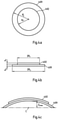
- Figure 4a shows a schematic view of an embodiment of a recording stack comprising a recording element 402 and a supporting element 409 according to the present invention.
- Fig. 4b shows a schematic side view of the embodiment shown in figure 4a . Both figures 4a and 4b show the recording stack in an initial state or initial position, i.e. prior to the recording and irradiating step, respectively.
- Figure 4c shows a schematic side view of the embodiment shown in figure 4a and 4b . The recording stack shown in figure 4c is in a bent state.
- the recording element 402 is laminated on the supporting element 409.
- the supporting element 409 and the recording element 402 are thin and ring-shaped plates. It shall be understood that according to other variants of the present invention, the form of at least one of the recording element and supporting element may be different. For instance, at least one of these elements may have a rectangular form.
- the supporting element 409 like a glass plate 409, has a radius R s and the recording element 402 has a radius R r . Furthermore, as can be seen from figure 4a , the radius R s is larger than the radius R r . The radius R of the recording stack is therefore radius R s .
- the recording stack comprising the recording element 402 and the supporting element 409 is bent.
- Figure 4c shows an exemplified embodiment of a bent recording stack.
- the recording stack is bent.
- the maximum bending deviation ⁇ max occurs at the center C of the recording stack.
- fringes occur if the maximum bending deviation ⁇ max exceeds a defined bending deviation threshold ⁇ thr , i.e., if ⁇ max > ⁇ thr .
- a recording element is laminated on a supporting element.
- the photopolymer film is directed towards the laser during recording.
- the resulting or produced holographic optical element shows a dark fringe.
- the recording is performed in the same way with only one difference.
- the photopolymer film is sandwiched between two supporting elements, for example two glass plates.
- the resulting holographic optical element does not show a fringe. It is noted that the present sandwich solution is not practical due to e.g., pressure marks on the produced holographic optical element.
- fringe formation must have been caused by a movement and/or a bending of the recording element during the recording process. If for example the object beam (e.g. the diffusor) or the reference beam would have moved or would have changed their shape or wavefront, fringes should have appeared in the reconstructed real image or should be visible in the real time interferometric setup. The latter means one observes the virtual image or the reference beam looking through the generated holographic element and both reference and object beam are on.
- object beam e.g. the diffusor
- the reference beam would have moved or would have changed their shape or wavefront
- the reason for the bending deviation, and thus, for the fringe formation is the asymmetric heating of the recording stack.
- the first one is shrinkage of the recording element during the irradiation step and the second one is asymmetric heating of the recording stack.
- Shrinkage is caused due to the volume reduction by photopolymerization in for example acrylate based photopolymers.
- the volume shrinkage is completely transferred in a thickness shrinkage s.
- the translational symmetry along the plate surface is broken and shear stresses might occur. This will give raise to torques that finally could bend the full recording stack.
- a large size recording element can be used in a recording experiment.
- fringe can be observed after the irradiating step.
- the same test is repeated. But in the repeated test, the laminated photopolymer layer is cut through the substrate down to the glass plate into small rectangles (similar size of the small size recording element) before exposure. The result of this test is that the fringe formation still occurs. Hence, shrinkage can be excluded from the possible sources of fringe formation.
- the only possibility to bend the recording stack is by asymmetric heating. That means that by the interaction with the recording light of at least one recording beam, one surface of the recording stack has a different temperature than the second surface during the exposure period. By thermal expansion this temperature difference over the thickness of the e.g. glass supporting plate can lead to a bending of the supporting element, and thus, to a bending of the total recording stack.
- asymmetric heating during the recording process and irradiating process, respectively can only happen either by conversion of the absorbed light into heat and/or by the heat of reaction (always during the exposure interval of duration t exp ).
- the heat of reaction is equal to the heat of polymerization. It has been found that the main source for the asymmetric heating during the recording process in photopolymers for example is the heat of polymerization.
- T ad ⁇ H P c P ⁇ f t exp
- ⁇ ( t exp ) denotes the fraction of full conversion which can be achieved during the exposure interval
- c P is the heat capacity per volume of the recording stack
- ⁇ H P is the exothermic heat of polymerization of the photopolymer layer.
- T ad E d ⁇ c P ⁇ 100 ⁇ T ini ⁇ Fresnel losses 100 % ⁇ 10
- E the recording dosage
- T ini its initial transmission at the recording wavelength ⁇
- d the thickness of the photoactive recording layer
- the resulting values differ from each other by a factor of approximately 10.
- the effect of the heat of polymerization is more than 13 times larger than that of the absorption of the recording light. Therefore, it would be more fruitful to avoid fringe formation in concentrating on photopolymer formulations with low ⁇ H P or keeping ⁇ ( t exp ) small, which means profiting from a long lasting dark reaction to achieve a high efficiency.
- the photopolymer formulation could be optimized to allow a long lasting and efficient dark reaction.
- Figure 5 shows an exemplified diagram of an embodiment of the method according to the present invention.
- a first step 501 at least one second parameter is provided.
- the at least one second parameter is responsible for the occurrence of a fringe.
- the occurrence of a fringe depends on the exceeding of a bending deviation threshold ⁇ thr .
- This threshold ⁇ thr depends on at least one second parameter. In other words, depending on at least one second parameter, a higher or lower bending during the irradiating step may be acceptable.
- the second parameter may be the slant angle ⁇ and/or the grating spacing A of the interference pattern formed by the at least on recording beam and/or the orientation of the resulting grating vector
- V V 0 ⁇ 1 ⁇ exp ⁇ ⁇ 0 ⁇ exp cos 2 ⁇ ⁇ ⁇ sin ⁇ ⁇ ⁇ ⁇ d ⁇
- V 0 is the fringe visibility of the interference pattern generated by the at least one recording beam
- A is the grating spacing
- ⁇ is the slant angle.
- V 0 can be equal to 1 if the reference beam and the object beam have the same power.
- V 0 is in the range between 0 and 1.
- the bending deviation threshold ⁇ thr can be determined such that only an exceeding of this threshold would result in a holographic optical element which comprises undesired fringes (step 502).
- the bending deviation threshold ⁇ thr depends on the type of recording scheme, like transmission scheme or reflection scheme, due to the influence of the slant angle ⁇ .
- the bending deviation threshold can also be determined in another way and can e.g. purely determined by experimental reference.
- the bending deviation threshold ⁇ thr is determined.
- the bending deviation threshold ⁇ thr can be determined depending on the at least one second parameter.
- the bending deviation threshold ⁇ thr can be calculated.
- the bending deviation threshold ⁇ thr is chosen such that if the bending during the recording step and irradiating step, respectively, is less than the bending deviation threshold ⁇ thr , a fringe will not occur.
- step 503 at least one first parameter is adjusted in such a way that in the following irradiating step (step 504) the maximum bending deviation ⁇ max does not exceed the previously determined bending deviation threshold ⁇ thr .
- the expected maximum bending deviation ⁇ max can be calculated on the following equation such that ⁇ max ⁇ ⁇ thr .
- d is the thickness of the photoactive recording layer.
- T ad is the adiabatic temperature increase by the exothermic heat of polymerization.
- ⁇ max 6 ⁇ 2 ⁇ T ad ⁇ d ⁇ d sup 0 ⁇ ⁇ CTE ⁇ R 2 dim ⁇ ⁇ ⁇ exp
- a supporting element having a low absolute value of the CTE can be used and/or the geometric dimensions can be adjusted for reducing R 2 dim and/or the normalized exposure time ⁇ exp and energy dosage E, respectively, can be adjusted for meeting the determined bending deviation threshold ⁇ thr .
- D is the thermal diffusion coefficient of the float glass comprising the supporting structure of the recording layer stack.
- ⁇ is the normalized radial coordinate
- ⁇ is the Poisson's ratio of the recording stack.
- the recording stack comprising the recording element and the supporting element is irradiated in step 504.
- the recording stack is irradiated by an object beam and a reference beam, as explained above.
- the result of the irradiating step is a holographic optical element comprising a desired pattern without any fringes.
- This is a typical power value at the upper level that can be achieved if a large size holographic optical element is recorded with a laser of an output power of 1 to 2 Watts.
- the thickness d of the recording layer is 15 ⁇ m and the adiabatic temperature increase T ad is 33.25 K.
- Table 1 h (mm) 0,5 1 3 10 19 30 ⁇ 0 (s) 0,072 0,27 2,6 29 103 258 ⁇ exp 1389 370 39 3,5 0,97 0,39 ⁇ isothermal ( ⁇ ) ⁇ exp 0,00071 0,0027 0,026 0,28 0,66 0,86
- R 2 dim R 2 /h 2 360000 90000 10000 900 249 100 ⁇ max ( ⁇ m) 0,56 0,56 0,56 0,54 0,35 0,18
- the recording dosage E is fixed at 15 mJ/cm 2 . If the exposure time t exp is varied the recording is done at different power densities P.
- ⁇ is the wavelength of the recording light in vacuum given in ⁇ m.
- Type refers to the character of the recording of the HOE. If the type is "Transmission" the reference and the object beam enter into the recording layer stack from the same side.
- ⁇ R is the angle in air of the reference beam measured towards the surface normal of the recording layer stack.
- ⁇ O is the angle in air of the object beam measured towards the surface normal of the recording layer stack.
- the surface normal is always meant as the surface normal that directs out of the recording layer stack into the air of the respective half space in which the respective recording beam exists.
- n is the refractive index of the photopolymer.
- equation (j) has to be replaced by equation (k) to estimate the maximum bending deviation ⁇ max in equation (b1).
- d cla ⁇ 1 ⁇ ⁇ 2 + 2 ⁇ ⁇ 2 ⁇ ln ⁇
Landscapes
- Physics & Mathematics (AREA)
- General Physics & Mathematics (AREA)
- Chemical & Material Sciences (AREA)
- Engineering & Computer Science (AREA)
- Materials Engineering (AREA)
- Manufacturing & Machinery (AREA)
- Health & Medical Sciences (AREA)
- Chemical Kinetics & Catalysis (AREA)
- Medicinal Chemistry (AREA)
- Polymers & Plastics (AREA)
- Organic Chemistry (AREA)
- Optics & Photonics (AREA)
- Holo Graphy (AREA)
- Diffracting Gratings Or Hologram Optical Elements (AREA)
Claims (9)
- Verfahren zum Herstellen eines holographischen optischen Elements, umfassend:Bereitstellen eines Aufzeichnungsstapels, der mindestens ein Aufzeichnungselement (202) aufweist, das auf mindestens ein Trägerelement (209) laminiert ist,Bestrahlen mindestens eines Teils des Aufzeichnungsstapels mit mindestens einem Aufzeichnungsstrahl (203, 206b) in einem Bestrahlungsschritt, während dem sich der Aufzeichnungsstapel biegt,Bestimmen einer Biegeabweichungsschwelle ξthr für den Aufzeichnungsstapel, so dass Streifen, die als dunkle Bereiche in der holographischen optischen Elementebene aufgrund einer asymmetrischen Erwärmung des Aufzeichnungsstapels während des Bestrahlungsschritts sichtbar sind, vermieden werden, undAnpassen mindestens eines ersten Parameters derart, dass eine vor dem Bestrahlungsschritt berechnete oder experimentell vorgegebene maximale Biegeabweichung ξ max des Aufzeichnungsstapels die Biegeabweichungsschwelle ξthr nicht überschreitet, wobei die maximale Biegeabweichung ξ max des Aufzeichnungsstapels die maximale Verschiebung eines Punkts des Aufzeichnungsstapels von einer Anfangsposition oder einem Anfangszustand des Aufzeichnungsstapels vor dem Bestrahlungsschritt zu einer maximalen Biegeposition während oder nach dem Bestrahlungsschritt bedeutet, wobei die Biegung durch die Bestrahlung verursacht wird, wobei der mindestens eine erste Parameter das Biegeverhalten des Aufzeichnungsstapels während des Bestrahlungsschrittes beeinflusst,wobei der erste Parameter ein Verhältnis Rdim der seitlichen Abmessungen des Aufzeichnungsstapels zu einer Dicke des Aufzeichnungsstapels ist, ein Wärmeausdehnungskoeffizient (CTE) des Aufzeichnungsstapels, ein Füllfaktor einer Aufzeichnungselementfläche gegenüber einer Stützelementfläche und/oder die Belichtungszeit texp bei einer festen Aufnahmedosis E.
- Verfahren nach Anspruch 1, wobei eine erwartete maximale Biegeabweichung ξ max vor dem Bestrahlungsschritt durch Berechnen der erwarteten maximalen Biegeabweichung ξ max bestimmt wird basierend auf Gleichungξ max = A · [|d sup (ρ = 0,σ)| · |CTE| · R 2 dim · β(τ exp)] wenn eine Halterung gestützt wird, und basierend auf Gleichungξ max = A· [|dcla (ρ = 0)| · |CTE| · R 2 dim· β(τ exp)] wenn die Halterung eingespannt ist,wobei A ein vordefinierter Skalierungsfaktor ist, d sup oder d cla eine normierte Biegeverformungsfunktion des Stützelements (209) ist, CTE ein Wärmeausdehnungskoeffizient des Aufzeichnungsstapels ist, Rdim das Verhältnis der seitlichen Abmessungen des Aufzeichnungsstapels zu einer Dicke des Aufzeichnungsstapels und β(τ exp)eine Funktion ist, die abhängig von einer normalisierten Belichtungszeit τ exp ist und gegeben ist durch

 wobei n der Brechungsindex eines Photopolymers als das Aufzeichnungselement (202) ist und die normalisierte Biegedeformationsfunktion d sup (ρ, σ) gegeben ist als
 wobei ρ die normalisierte radiale Koordinate und σ das Poisson-Verhältnis des Aufzeichnungsstapels ist und d sup die Biegung des Aufzeichnungsstapels beschreibt, wenn die Kanten der Aufzeichnungsplatte (ρ = 1) von einer Halterung an einem Rahmen während der Aufzeichnung getragen werden, was bedeutet, dass d sup(ρ = 1, σ) entlang dieser Kanten im Wesentlichen gleich 0 ist, und
- Verfahren nach einem der Ansprüche 1 bis 2, ferner umfassend:Bestimmen der Biegeabweichungsschwelle ξthr für den Aufzeichnungsstapel in Abhängigkeit von mindestens einem zweiten Parameter,wobei der zweite Parameter ein Neigungswinkel α zwischen dem Gittervektor K des aufgezeichneten Gitters und der Aufzeichnungsstapeloberfläche und/oder ein Gitterabstand A des durch den mindestens einen Aufzeichnungsstrahl gebildeten Interferenzmusters ist.
- Verfahren nach einem der Ansprüche 1 bis 3, wobei der maximale Biegeabweichungsschwellenwert ξ max gleich oder kleiner als

- Verfahren nach einem der Ansprüche 1 bis 4, wobei der Aufzeichnungsstapel im Bestrahlungsschritt mit einem Referenzstrahl (203) und einem Objektstrahl (206b) bestrahlt wird.
- Verfahren nach Anspruch 5, wobei mindestens einer von dem Referenzstrahl (203) oder dem Objektstrahl (206b) von einem Laser, einer Laserdiode oder einer gerichteten Lichtquelle erzeugt wird.
- Verfahren nach einem der Ansprüche 1 bis 6, wobei das Aufzeichnungselement (202) Photoresistmaterial, Photopolymermaterial, Silberhalogenidmaterial, dichromatiertes Gelatinematerial, photochromes Material oder photorefraktives Material aufweist.
- Verfahren nach einem der Ansprüche 1 bis 6, wobei das Aufzeichnungselement (202) einen Photopolymerfilm aufweist, der eine vernetzte Matrix und Schreibmonomere aufweist, aufweisend eine vernetzte Matrix und Monomere auf Acrylatbasis.
- Verfahren nach einem der Ansprüche 1 bis 8, wobei das Stützelement (209) eine Glasplatte, eine Glasplatte aus Borosilikatglas, eine Keramikglasplatte, Quarzglas oder eine Quarzglasplatte oder eine Floatglasplatte ist, wobei das Stützelement (209) einen Absolutwert eines Wärmeausdehnungskoeffizienten (CTE) gleich oder kleiner als 7 x 10⁻⁶ K-1 hat.
Applications Claiming Priority (1)
| Application Number | Priority Date | Filing Date | Title |
|---|---|---|---|
| US14/695,610 US10073416B2 (en) | 2015-04-24 | 2015-04-24 | Method for producing a holographic optical element |
Publications (2)
| Publication Number | Publication Date |
|---|---|
| EP3086186A1 EP3086186A1 (de) | 2016-10-26 |
| EP3086186B1 true EP3086186B1 (de) | 2022-02-23 |
Family
ID=55910746
Family Applications (1)
| Application Number | Title | Priority Date | Filing Date |
|---|---|---|---|
| EP16166372.9A Active EP3086186B1 (de) | 2015-04-24 | 2016-04-21 | Verfahren zur herstellung eines holografischen optischen elements |
Country Status (6)
| Country | Link |
|---|---|
| US (2) | US10073416B2 (de) |
| EP (1) | EP3086186B1 (de) |
| JP (1) | JP6259858B2 (de) |
| KR (1) | KR101941958B1 (de) |
| CN (1) | CN106066592B (de) |
| TW (1) | TWI588628B (de) |
Families Citing this family (5)
| Publication number | Priority date | Publication date | Assignee | Title |
|---|---|---|---|---|
| JP2804393B2 (ja) | 1991-07-31 | 1998-09-24 | 京セラ株式会社 | セラミックヒータ |
| US10073416B2 (en) * | 2015-04-24 | 2018-09-11 | Lg Display Co., Ltd. | Method for producing a holographic optical element |
| KR102742145B1 (ko) * | 2020-09-14 | 2024-12-16 | 주식회사 엘지화학 | 홀로그래픽 광학 소자 및 그의 제조방법 |
| TWI867771B (zh) * | 2022-10-05 | 2024-12-21 | 宏達國際電子股份有限公司 | 製造光學元件的方法及投影裝置 |
| CN115639643B (zh) * | 2022-12-23 | 2023-04-07 | 深圳珑璟光电科技有限公司 | 体全息光栅及其曝光参数确定方法、制作方法、系统 |
Family Cites Families (17)
| Publication number | Priority date | Publication date | Assignee | Title |
|---|---|---|---|---|
| GB187904576A (en) * | 1879-11-04 | Thomas Alva Edison | Incandescent lamps | |
| BE758103A (nl) * | 1969-10-29 | 1971-04-28 | Agfa Gevaert Nv | Fijnkorrelige fotografische zilverhalogenide emulsies |
| JPH02157708A (ja) | 1988-12-09 | 1990-06-18 | Ricoh Co Ltd | グレーテイング素子及びその製造方法 |
| JPH05165388A (ja) | 1991-12-11 | 1993-07-02 | Dainippon Printing Co Ltd | ホログラム |
| JP2003322713A (ja) | 2002-04-30 | 2003-11-14 | Ricoh Co Ltd | 回折光学素子およびその製造方法および光ピックアップ装置および光ディスクドライブ装置 |
| JP4204809B2 (ja) | 2002-06-14 | 2009-01-07 | 株式会社リコー | 回折光学素子の製造方法 |
| JP2007017521A (ja) | 2005-07-05 | 2007-01-25 | Lintec Corp | 平面型光導波路作製用樹脂シート |
| JP2007148038A (ja) | 2005-11-28 | 2007-06-14 | Fujifilm Corp | 光記録媒体及びその製造方法 |
| JP2008076674A (ja) | 2006-09-20 | 2008-04-03 | Fujifilm Corp | ホログラム記録媒体用組成物、並びにホログラム記録媒体及びその製造方法 |
| JP2009059414A (ja) | 2007-08-31 | 2009-03-19 | Victor Co Of Japan Ltd | ホログラフィック記録再生装置及びホログラフィック記録再生方法 |
| US8254418B2 (en) | 2008-09-19 | 2012-08-28 | Inphase Technologies, Inc. | Method for finding and tracking single-mode operation point of external cavity diode lasers |
| TW201037032A (en) | 2009-04-10 | 2010-10-16 | Univ Chung Yuan Christian | Blue ray sensitive polymer engineering storage type material and producing method thereof |
| KR101804591B1 (ko) * | 2010-02-02 | 2017-12-04 | 바이엘 인텔렉쳐 프로퍼티 게엠베하 | 에스테르-기재 기록 단량체를 갖는 광중합체 배합물 |
| JP2014517931A (ja) * | 2011-04-28 | 2014-07-24 | ドルビー ラボラトリーズ ライセンシング コーポレイション | クロスbefコリメータおよび偏光保存拡散器を備えるデュアルパネルディスプレイ |
| JP2015118717A (ja) | 2012-03-30 | 2015-06-25 | リンテック株式会社 | 多層光記録媒体の製造方法 |
| JP6064446B2 (ja) | 2012-08-31 | 2017-01-25 | セイコーエプソン株式会社 | 記録装置 |
| US10073416B2 (en) * | 2015-04-24 | 2018-09-11 | Lg Display Co., Ltd. | Method for producing a holographic optical element |
-
2015
- 2015-04-24 US US14/695,610 patent/US10073416B2/en active Active
-
2016
- 2016-04-21 EP EP16166372.9A patent/EP3086186B1/de active Active
- 2016-04-22 CN CN201610258277.3A patent/CN106066592B/zh active Active
- 2016-04-22 KR KR1020160049501A patent/KR101941958B1/ko active Active
- 2016-04-22 TW TW105112652A patent/TWI588628B/zh active
- 2016-04-25 JP JP2016086831A patent/JP6259858B2/ja active Active
-
2018
- 2018-08-08 US US16/058,834 patent/US10921751B2/en active Active
Also Published As
| Publication number | Publication date |
|---|---|
| US20180348704A1 (en) | 2018-12-06 |
| JP2016206677A (ja) | 2016-12-08 |
| CN106066592A (zh) | 2016-11-02 |
| TWI588628B (zh) | 2017-06-21 |
| JP6259858B2 (ja) | 2018-01-10 |
| KR101941958B1 (ko) | 2019-04-12 |
| TW201640235A (zh) | 2016-11-16 |
| US10921751B2 (en) | 2021-02-16 |
| EP3086186A1 (de) | 2016-10-26 |
| CN106066592B (zh) | 2019-10-22 |
| US10073416B2 (en) | 2018-09-11 |
| KR20160127320A (ko) | 2016-11-03 |
| US20160313696A1 (en) | 2016-10-27 |
Similar Documents
| Publication | Publication Date | Title |
|---|---|---|
| US10921751B2 (en) | Method for producing a holographic optical element | |
| CN108780296B (zh) | 照明装置 | |
| Khonina et al. | Exploring diffractive optical elements and their potential in free space optics and imaging‐A comprehensive review | |
| US11474347B2 (en) | Waveguide and devices for data reflection | |
| US9785114B2 (en) | Method and device for the layered production of thin volume grid stacks, and beam combiner for a holographic display | |
| TWI540287B (zh) | The direct view shows the light emitting unit | |
| WO2019217453A1 (en) | Methods and apparatuses for copying a diversity of hologram prescriptions from a common master | |
| US9541900B2 (en) | Method for producing a beam shaping holographic optical element | |
| US20200018885A1 (en) | Backlight Unit, Method for Manufacturing the Same and Display Device | |
| WO2007015141A2 (en) | Laser illuminator | |
| KR20130129256A (ko) | 관찰자 트래킹을 위한 조합된 광변조 장치 | |
| KR20150043391A (ko) | 아웃-커플링 부재를 갖는 도광판 | |
| KR20150043390A (ko) | 아웃-커플링 부재를 갖는 도광판 | |
| JP6882316B2 (ja) | ワイヤグリッド偏光板製造方法 | |
| CN105929474A (zh) | 全息聚合物分散液晶变间距光栅的制备方法 | |
| US20230417962A1 (en) | System and method for fabricating polarization selective element | |
| JP6146626B2 (ja) | 光学素子、照明装置、投射装置および投射型映像表示装置 | |
| Bruder et al. | Thin combiner optics utilizing volume holographic optical elements (vHOEs) using Bayfol HX photopolymer film | |
| RU2762176C1 (ru) | Устройство для расширения пучка оптического излучения и способ расширения пучка оптического излучения для когерентной подсветки | |
| Bruder et al. | Generating diffraction efficiency profiles in Bayfol HX vHOEs | |
| US11860573B1 (en) | System and method for fabricating polarization holograms | |
| CN120295076A (zh) | 体全息元件的制备方法、体全息元件及增强现实3d显示装置 | |
| US20240085602A1 (en) | System and method for fabricating polarization holograms | |
| Mohammadian | Development of Holographic Phase Masks for Wavefront Shaping | |
| CN117008235A (zh) | 全像光学元件的制造装置及其制造方法 |
Legal Events
| Date | Code | Title | Description |
|---|---|---|---|
| PUAI | Public reference made under article 153(3) epc to a published international application that has entered the european phase |
Free format text: ORIGINAL CODE: 0009012 |
|
| 17P | Request for examination filed |
Effective date: 20160421 |
|
| AK | Designated contracting states |
Kind code of ref document: A1 Designated state(s): AL AT BE BG CH CY CZ DE DK EE ES FI FR GB GR HR HU IE IS IT LI LT LU LV MC MK MT NL NO PL PT RO RS SE SI SK SM TR |
|
| AX | Request for extension of the european patent |
Extension state: BA ME |
|
| RBV | Designated contracting states (corrected) |
Designated state(s): AL AT BE BG CH CY CZ DE DK EE ES FI FR GB GR HR HU IE IS IT LI LT LU LV MC MK MT NL NO PL PT RO RS SE SI SK SM TR |
|
| STAA | Information on the status of an ep patent application or granted ep patent |
Free format text: STATUS: EXAMINATION IS IN PROGRESS |
|
| 17Q | First examination report despatched |
Effective date: 20191105 |
|
| GRAP | Despatch of communication of intention to grant a patent |
Free format text: ORIGINAL CODE: EPIDOSNIGR1 |
|
| STAA | Information on the status of an ep patent application or granted ep patent |
Free format text: STATUS: GRANT OF PATENT IS INTENDED |
|
| RIC1 | Information provided on ipc code assigned before grant |
Ipc: G02B 5/32 20060101ALN20210924BHEP Ipc: G03H 1/02 20060101ALI20210924BHEP Ipc: G03H 1/04 20060101AFI20210924BHEP |
|
| INTG | Intention to grant announced |
Effective date: 20211011 |
|
| GRAS | Grant fee paid |
Free format text: ORIGINAL CODE: EPIDOSNIGR3 |
|
| GRAA | (expected) grant |
Free format text: ORIGINAL CODE: 0009210 |
|
| STAA | Information on the status of an ep patent application or granted ep patent |
Free format text: STATUS: THE PATENT HAS BEEN GRANTED |
|
| AK | Designated contracting states |
Kind code of ref document: B1 Designated state(s): AL AT BE BG CH CY CZ DE DK EE ES FI FR GB GR HR HU IE IS IT LI LT LU LV MC MK MT NL NO PL PT RO RS SE SI SK SM TR |
|
| REG | Reference to a national code |
Ref country code: GB Ref legal event code: FG4D |
|
| REG | Reference to a national code |
Ref country code: CH Ref legal event code: EP |
|
| REG | Reference to a national code |
Ref country code: AT Ref legal event code: REF Ref document number: 1470926 Country of ref document: AT Kind code of ref document: T Effective date: 20220315 |
|
| REG | Reference to a national code |
Ref country code: IE Ref legal event code: FG4D |
|
| REG | Reference to a national code |
Ref country code: DE Ref legal event code: R096 Ref document number: 602016069288 Country of ref document: DE |
|
| REG | Reference to a national code |
Ref country code: LT Ref legal event code: MG9D |
|
| REG | Reference to a national code |
Ref country code: NL Ref legal event code: MP Effective date: 20220223 |
|
| REG | Reference to a national code |
Ref country code: AT Ref legal event code: MK05 Ref document number: 1470926 Country of ref document: AT Kind code of ref document: T Effective date: 20220223 |
|
| PG25 | Lapsed in a contracting state [announced via postgrant information from national office to epo] |
Ref country code: SE Free format text: LAPSE BECAUSE OF FAILURE TO SUBMIT A TRANSLATION OF THE DESCRIPTION OR TO PAY THE FEE WITHIN THE PRESCRIBED TIME-LIMIT Effective date: 20220223 Ref country code: RS Free format text: LAPSE BECAUSE OF FAILURE TO SUBMIT A TRANSLATION OF THE DESCRIPTION OR TO PAY THE FEE WITHIN THE PRESCRIBED TIME-LIMIT Effective date: 20220223 Ref country code: PT Free format text: LAPSE BECAUSE OF FAILURE TO SUBMIT A TRANSLATION OF THE DESCRIPTION OR TO PAY THE FEE WITHIN THE PRESCRIBED TIME-LIMIT Effective date: 20220623 Ref country code: NO Free format text: LAPSE BECAUSE OF FAILURE TO SUBMIT A TRANSLATION OF THE DESCRIPTION OR TO PAY THE FEE WITHIN THE PRESCRIBED TIME-LIMIT Effective date: 20220523 Ref country code: NL Free format text: LAPSE BECAUSE OF FAILURE TO SUBMIT A TRANSLATION OF THE DESCRIPTION OR TO PAY THE FEE WITHIN THE PRESCRIBED TIME-LIMIT Effective date: 20220223 Ref country code: LT Free format text: LAPSE BECAUSE OF FAILURE TO SUBMIT A TRANSLATION OF THE DESCRIPTION OR TO PAY THE FEE WITHIN THE PRESCRIBED TIME-LIMIT Effective date: 20220223 Ref country code: HR Free format text: LAPSE BECAUSE OF FAILURE TO SUBMIT A TRANSLATION OF THE DESCRIPTION OR TO PAY THE FEE WITHIN THE PRESCRIBED TIME-LIMIT Effective date: 20220223 Ref country code: ES Free format text: LAPSE BECAUSE OF FAILURE TO SUBMIT A TRANSLATION OF THE DESCRIPTION OR TO PAY THE FEE WITHIN THE PRESCRIBED TIME-LIMIT Effective date: 20220223 Ref country code: BG Free format text: LAPSE BECAUSE OF FAILURE TO SUBMIT A TRANSLATION OF THE DESCRIPTION OR TO PAY THE FEE WITHIN THE PRESCRIBED TIME-LIMIT Effective date: 20220523 |
|
| PG25 | Lapsed in a contracting state [announced via postgrant information from national office to epo] |
Ref country code: PL Free format text: LAPSE BECAUSE OF FAILURE TO SUBMIT A TRANSLATION OF THE DESCRIPTION OR TO PAY THE FEE WITHIN THE PRESCRIBED TIME-LIMIT Effective date: 20220223 Ref country code: LV Free format text: LAPSE BECAUSE OF FAILURE TO SUBMIT A TRANSLATION OF THE DESCRIPTION OR TO PAY THE FEE WITHIN THE PRESCRIBED TIME-LIMIT Effective date: 20220223 Ref country code: GR Free format text: LAPSE BECAUSE OF FAILURE TO SUBMIT A TRANSLATION OF THE DESCRIPTION OR TO PAY THE FEE WITHIN THE PRESCRIBED TIME-LIMIT Effective date: 20220524 Ref country code: FI Free format text: LAPSE BECAUSE OF FAILURE TO SUBMIT A TRANSLATION OF THE DESCRIPTION OR TO PAY THE FEE WITHIN THE PRESCRIBED TIME-LIMIT Effective date: 20220223 Ref country code: AT Free format text: LAPSE BECAUSE OF FAILURE TO SUBMIT A TRANSLATION OF THE DESCRIPTION OR TO PAY THE FEE WITHIN THE PRESCRIBED TIME-LIMIT Effective date: 20220223 |
|
| PG25 | Lapsed in a contracting state [announced via postgrant information from national office to epo] |
Ref country code: IS Free format text: LAPSE BECAUSE OF FAILURE TO SUBMIT A TRANSLATION OF THE DESCRIPTION OR TO PAY THE FEE WITHIN THE PRESCRIBED TIME-LIMIT Effective date: 20220623 |
|
| PG25 | Lapsed in a contracting state [announced via postgrant information from national office to epo] |
Ref country code: SM Free format text: LAPSE BECAUSE OF FAILURE TO SUBMIT A TRANSLATION OF THE DESCRIPTION OR TO PAY THE FEE WITHIN THE PRESCRIBED TIME-LIMIT Effective date: 20220223 Ref country code: SK Free format text: LAPSE BECAUSE OF FAILURE TO SUBMIT A TRANSLATION OF THE DESCRIPTION OR TO PAY THE FEE WITHIN THE PRESCRIBED TIME-LIMIT Effective date: 20220223 Ref country code: RO Free format text: LAPSE BECAUSE OF FAILURE TO SUBMIT A TRANSLATION OF THE DESCRIPTION OR TO PAY THE FEE WITHIN THE PRESCRIBED TIME-LIMIT Effective date: 20220223 Ref country code: EE Free format text: LAPSE BECAUSE OF FAILURE TO SUBMIT A TRANSLATION OF THE DESCRIPTION OR TO PAY THE FEE WITHIN THE PRESCRIBED TIME-LIMIT Effective date: 20220223 Ref country code: DK Free format text: LAPSE BECAUSE OF FAILURE TO SUBMIT A TRANSLATION OF THE DESCRIPTION OR TO PAY THE FEE WITHIN THE PRESCRIBED TIME-LIMIT Effective date: 20220223 Ref country code: CZ Free format text: LAPSE BECAUSE OF FAILURE TO SUBMIT A TRANSLATION OF THE DESCRIPTION OR TO PAY THE FEE WITHIN THE PRESCRIBED TIME-LIMIT Effective date: 20220223 |
|
| REG | Reference to a national code |
Ref country code: DE Ref legal event code: R097 Ref document number: 602016069288 Country of ref document: DE |
|
| PG25 | Lapsed in a contracting state [announced via postgrant information from national office to epo] |
Ref country code: AL Free format text: LAPSE BECAUSE OF FAILURE TO SUBMIT A TRANSLATION OF THE DESCRIPTION OR TO PAY THE FEE WITHIN THE PRESCRIBED TIME-LIMIT Effective date: 20220223 |
|
| PLBE | No opposition filed within time limit |
Free format text: ORIGINAL CODE: 0009261 |
|
| STAA | Information on the status of an ep patent application or granted ep patent |
Free format text: STATUS: NO OPPOSITION FILED WITHIN TIME LIMIT |
|
| REG | Reference to a national code |
Ref country code: BE Ref legal event code: MM Effective date: 20220430 |
|
| PG25 | Lapsed in a contracting state [announced via postgrant information from national office to epo] |
Ref country code: MC Free format text: LAPSE BECAUSE OF FAILURE TO SUBMIT A TRANSLATION OF THE DESCRIPTION OR TO PAY THE FEE WITHIN THE PRESCRIBED TIME-LIMIT Effective date: 20220223 Ref country code: LU Free format text: LAPSE BECAUSE OF NON-PAYMENT OF DUE FEES Effective date: 20220421 |
|
| 26N | No opposition filed |
Effective date: 20221124 |
|
| PG25 | Lapsed in a contracting state [announced via postgrant information from national office to epo] |
Ref country code: SI Free format text: LAPSE BECAUSE OF FAILURE TO SUBMIT A TRANSLATION OF THE DESCRIPTION OR TO PAY THE FEE WITHIN THE PRESCRIBED TIME-LIMIT Effective date: 20220223 Ref country code: BE Free format text: LAPSE BECAUSE OF NON-PAYMENT OF DUE FEES Effective date: 20220430 |
|
| PG25 | Lapsed in a contracting state [announced via postgrant information from national office to epo] |
Ref country code: IE Free format text: LAPSE BECAUSE OF NON-PAYMENT OF DUE FEES Effective date: 20220421 |
|
| PG25 | Lapsed in a contracting state [announced via postgrant information from national office to epo] |
Ref country code: IT Free format text: LAPSE BECAUSE OF FAILURE TO SUBMIT A TRANSLATION OF THE DESCRIPTION OR TO PAY THE FEE WITHIN THE PRESCRIBED TIME-LIMIT Effective date: 20220223 |
|
| PG25 | Lapsed in a contracting state [announced via postgrant information from national office to epo] |
Ref country code: HU Free format text: LAPSE BECAUSE OF FAILURE TO SUBMIT A TRANSLATION OF THE DESCRIPTION OR TO PAY THE FEE WITHIN THE PRESCRIBED TIME-LIMIT; INVALID AB INITIO Effective date: 20160421 |
|
| PG25 | Lapsed in a contracting state [announced via postgrant information from national office to epo] |
Ref country code: MK Free format text: LAPSE BECAUSE OF FAILURE TO SUBMIT A TRANSLATION OF THE DESCRIPTION OR TO PAY THE FEE WITHIN THE PRESCRIBED TIME-LIMIT Effective date: 20220223 Ref country code: CY Free format text: LAPSE BECAUSE OF FAILURE TO SUBMIT A TRANSLATION OF THE DESCRIPTION OR TO PAY THE FEE WITHIN THE PRESCRIBED TIME-LIMIT Effective date: 20220223 |
|
| PGFP | Annual fee paid to national office [announced via postgrant information from national office to epo] |
Ref country code: FR Payment date: 20240226 Year of fee payment: 9 |
|
| PG25 | Lapsed in a contracting state [announced via postgrant information from national office to epo] |
Ref country code: TR Free format text: LAPSE BECAUSE OF FAILURE TO SUBMIT A TRANSLATION OF THE DESCRIPTION OR TO PAY THE FEE WITHIN THE PRESCRIBED TIME-LIMIT Effective date: 20220223 |
|
| PGFP | Annual fee paid to national office [announced via postgrant information from national office to epo] |
Ref country code: CH Payment date: 20240501 Year of fee payment: 9 |
|
| PG25 | Lapsed in a contracting state [announced via postgrant information from national office to epo] |
Ref country code: MT Free format text: LAPSE BECAUSE OF FAILURE TO SUBMIT A TRANSLATION OF THE DESCRIPTION OR TO PAY THE FEE WITHIN THE PRESCRIBED TIME-LIMIT Effective date: 20220223 |
|
| PGFP | Annual fee paid to national office [announced via postgrant information from national office to epo] |
Ref country code: DE Payment date: 20250220 Year of fee payment: 10 |
|
| REG | Reference to a national code |
Ref country code: CH Ref legal event code: H13 Free format text: ST27 STATUS EVENT CODE: U-0-0-H10-H13 (AS PROVIDED BY THE NATIONAL OFFICE) Effective date: 20251125 |
|
| PG25 | Lapsed in a contracting state [announced via postgrant information from national office to epo] |
Ref country code: FR Free format text: LAPSE BECAUSE OF NON-PAYMENT OF DUE FEES Effective date: 20250430 |
|
| PG25 | Lapsed in a contracting state [announced via postgrant information from national office to epo] |
Ref country code: CH Free format text: LAPSE BECAUSE OF NON-PAYMENT OF DUE FEES Effective date: 20250430 |
|
| PGFP | Annual fee paid to national office [announced via postgrant information from national office to epo] |
Ref country code: GB Payment date: 20260224 Year of fee payment: 11 |