EP3086147A1 - Boîtiers de dissipation d'énergie pour un fonctionnement haute puissance de composants de fibre optique - Google Patents
Boîtiers de dissipation d'énergie pour un fonctionnement haute puissance de composants de fibre optique Download PDFInfo
- Publication number
- EP3086147A1 EP3086147A1 EP16168378.4A EP16168378A EP3086147A1 EP 3086147 A1 EP3086147 A1 EP 3086147A1 EP 16168378 A EP16168378 A EP 16168378A EP 3086147 A1 EP3086147 A1 EP 3086147A1
- Authority
- EP
- European Patent Office
- Prior art keywords
- optical fiber
- power
- fiber component
- heat sink
- cavity
- Prior art date
- Legal status (The legal status is an assumption and is not a legal conclusion. Google has not performed a legal analysis and makes no representation as to the accuracy of the status listed.)
- Granted
Links
Images


Classifications
-
- H—ELECTRICITY
- H01—ELECTRIC ELEMENTS
- H01S—DEVICES USING THE PROCESS OF LIGHT AMPLIFICATION BY STIMULATED EMISSION OF RADIATION [LASER] TO AMPLIFY OR GENERATE LIGHT; DEVICES USING STIMULATED EMISSION OF ELECTROMAGNETIC RADIATION IN WAVE RANGES OTHER THAN OPTICAL
- H01S3/00—Lasers, i.e. devices using stimulated emission of electromagnetic radiation in the infrared, visible or ultraviolet wave range
- H01S3/05—Construction or shape of optical resonators; Accommodation of active medium therein; Shape of active medium
- H01S3/06—Construction or shape of active medium
- H01S3/063—Waveguide lasers, i.e. whereby the dimensions of the waveguide are of the order of the light wavelength
- H01S3/067—Fibre lasers
- H01S3/06704—Housings; Packages
-
- G—PHYSICS
- G02—OPTICS
- G02B—OPTICAL ELEMENTS, SYSTEMS OR APPARATUS
- G02B6/00—Light guides; Structural details of arrangements comprising light guides and other optical elements, e.g. couplings
- G02B6/24—Coupling light guides
- G02B6/36—Mechanical coupling means
- G02B6/3628—Mechanical coupling means for mounting fibres to supporting carriers
- G02B6/3632—Mechanical coupling means for mounting fibres to supporting carriers characterised by the cross-sectional shape of the mechanical coupling means
- G02B6/3636—Mechanical coupling means for mounting fibres to supporting carriers characterised by the cross-sectional shape of the mechanical coupling means the mechanical coupling means being grooves
-
- G—PHYSICS
- G02—OPTICS
- G02B—OPTICAL ELEMENTS, SYSTEMS OR APPARATUS
- G02B6/00—Light guides; Structural details of arrangements comprising light guides and other optical elements, e.g. couplings
- G02B6/02—Optical fibres with cladding with or without a coating
- G02B6/02057—Optical fibres with cladding with or without a coating comprising gratings
- G02B6/02076—Refractive index modulation gratings, e.g. Bragg gratings
- G02B6/02171—Refractive index modulation gratings, e.g. Bragg gratings characterised by means for compensating environmentally induced changes
- G02B6/02176—Refractive index modulation gratings, e.g. Bragg gratings characterised by means for compensating environmentally induced changes due to temperature fluctuations
- G02B6/0218—Refractive index modulation gratings, e.g. Bragg gratings characterised by means for compensating environmentally induced changes due to temperature fluctuations using mounting means, e.g. by using a combination of materials having different thermal expansion coefficients
-
- G—PHYSICS
- G02—OPTICS
- G02B—OPTICAL ELEMENTS, SYSTEMS OR APPARATUS
- G02B6/00—Light guides; Structural details of arrangements comprising light guides and other optical elements, e.g. couplings
- G02B6/10—Light guides; Structural details of arrangements comprising light guides and other optical elements, e.g. couplings of the optical waveguide type
- G02B6/14—Mode converters
-
- G—PHYSICS
- G02—OPTICS
- G02B—OPTICAL ELEMENTS, SYSTEMS OR APPARATUS
- G02B6/00—Light guides; Structural details of arrangements comprising light guides and other optical elements, e.g. couplings
- G02B6/24—Coupling light guides
- G02B6/241—Light guide terminations
- G02B6/243—Light guide terminations as light absorbers
-
- G—PHYSICS
- G02—OPTICS
- G02B—OPTICAL ELEMENTS, SYSTEMS OR APPARATUS
- G02B6/00—Light guides; Structural details of arrangements comprising light guides and other optical elements, e.g. couplings
- G02B6/24—Coupling light guides
- G02B6/255—Splicing of light guides, e.g. by fusion or bonding
- G02B6/2558—Reinforcement of splice joint
-
- G—PHYSICS
- G02—OPTICS
- G02B—OPTICAL ELEMENTS, SYSTEMS OR APPARATUS
- G02B6/00—Light guides; Structural details of arrangements comprising light guides and other optical elements, e.g. couplings
- G02B6/24—Coupling light guides
- G02B6/42—Coupling light guides with opto-electronic elements
- G02B6/4296—Coupling light guides with opto-electronic elements coupling with sources of high radiant energy, e.g. high power lasers, high temperature light sources
-
- H—ELECTRICITY
- H01—ELECTRIC ELEMENTS
- H01S—DEVICES USING THE PROCESS OF LIGHT AMPLIFICATION BY STIMULATED EMISSION OF RADIATION [LASER] TO AMPLIFY OR GENERATE LIGHT; DEVICES USING STIMULATED EMISSION OF ELECTROMAGNETIC RADIATION IN WAVE RANGES OTHER THAN OPTICAL
- H01S3/00—Lasers, i.e. devices using stimulated emission of electromagnetic radiation in the infrared, visible or ultraviolet wave range
- H01S3/02—Constructional details
- H01S3/04—Arrangements for thermal management
- H01S3/042—Arrangements for thermal management for solid state lasers
-
- Y—GENERAL TAGGING OF NEW TECHNOLOGICAL DEVELOPMENTS; GENERAL TAGGING OF CROSS-SECTIONAL TECHNOLOGIES SPANNING OVER SEVERAL SECTIONS OF THE IPC; TECHNICAL SUBJECTS COVERED BY FORMER USPC CROSS-REFERENCE ART COLLECTIONS [XRACs] AND DIGESTS
- Y10—TECHNICAL SUBJECTS COVERED BY FORMER USPC
- Y10T—TECHNICAL SUBJECTS COVERED BY FORMER US CLASSIFICATION
- Y10T156/00—Adhesive bonding and miscellaneous chemical manufacture
- Y10T156/10—Methods of surface bonding and/or assembly therefor
-
- Y—GENERAL TAGGING OF NEW TECHNOLOGICAL DEVELOPMENTS; GENERAL TAGGING OF CROSS-SECTIONAL TECHNOLOGIES SPANNING OVER SEVERAL SECTIONS OF THE IPC; TECHNICAL SUBJECTS COVERED BY FORMER USPC CROSS-REFERENCE ART COLLECTIONS [XRACs] AND DIGESTS
- Y10—TECHNICAL SUBJECTS COVERED BY FORMER USPC
- Y10T—TECHNICAL SUBJECTS COVERED BY FORMER US CLASSIFICATION
- Y10T29/00—Metal working
- Y10T29/49—Method of mechanical manufacture
- Y10T29/49826—Assembling or joining
Definitions
- the present invention relates to packages for optical fiber components. More particularly, it relates to packages for dissipating at least one of heat power or optical power from an optical fiber component of a device.
- Fiber lasers are becoming the laser of choice in numerous industrial applications. More and more, these applications require the laser to emit at the kilowatt power level which puts a strain on the power handling capabilities of laser components.
- DCOF double clad optical fibers
- FIG. 2 depicts exemplary optical fiber components of an optical fiber device and indicates possible sites of catastrophic failures due to thermal degradation.
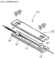
- FIG. 3 shows such a package 10' for an optical fiber device 12' according to Wetter.
- the optical fiber component package has a high thermal conductivity packaging substrate, 18' and 20', surrounding the optical fiber device 12' and has adhesive bonds, 14' and 16', at each end anchoring the optical fiber device to the substrate.
- the adhesive bonds are made of a material that has high transparency in damp heat as well as a high glass transition temperature and is capable of withstanding temperatures of over 100 °C.
- the proposed adhesives in Wetter et al. are poor thermal conductors, which can cause thermal degradation and failure.
- a package for dissipating at least one of heat power or optical power from an optical fiber component of a device including:
- the power-dissipative material may include optically transparent material having a refractive index conducive to total-internal reflection optical guidance of light within the optical fiber component.
- the power-dissipative material may include optically transparent material for mode stripping having a refractive index equal to or greater than a refractive index of the temperature-sensitive portion of the optical fiber component.
- the power-dissipative material may include a heat conducting material.
- the heat sink packaging receptacle may include at least one channel extending between the cavity and either the first end or the second end of the heat sink packaging receptacle, the channel being in intimate contact with a cladding of the optical fiber component for dissipating at least one of heat power or optical power from the optical fiber component.
- the package may include an adhesive proximate each of the first end and the second end of the heat sink packaging receptacle for affixing the optical fiber component to the heat sink packaging receptacle.
- the heat sink packaging receptacle preferably includes a heat sink substrate and a heat sink cover engaged in substantially mating relation to define the cavity.
- a package for dissipating at least one of heat power or optical power from an optical fiber component of a device the optical fiber component having a light-guiding core and a cladding surrounding the core.
- the package includes a heat sink packaging receptacle for accommodating the optical fiber component, the heat sink packaging receptacle including:
- the package may include an adhesive for affixing the optical fiber component to the heat sink packaging receptacle, the adhesive placed at an adhesive bond site that is located within the channel distal to the cavity.
- the adhesive may have a refractive index greater than a refractive index of the cladding of the optical fiber component.
- the adhesive is preferably optically transparent and temperature resistant.
- the cavity may include heat-insensitive gas surrounding the temperature-sensitive portion of the optical fiber component.
- the cavity may contain a power-dissipative material for dissipating at least one of heat power or optical power, the power-dissipative material surrounding the temperature sensitive portion of the optical fiber component.
- the temperature-sensitive portion of the optical fiber component receivable by the cavity may be stripped of the cladding.
- the heat sink packaging receptacle preferably includes a heat sink substrate and a heat sink cover engaged in substantially mating relation to define the cavity.
- a method of packaging a high-power optical fiber component of a device for dissipating at least one of heat power or optical power therefrom includes the steps of:
- the step of introducing a power-dissipative material inside the cavity may include liquid filling the power-dissipative material into the cavity and solidifying in place the power-dissipative material.
- the method may further include the step of fixing the optical fiber component to the heat sink substrate using adhesive at an adhesive bond site proximate an end of the heat sink substrate.
- the method may further include a step, before the step of inserting the optical fiber component, of recoating a previously uncoated section of the temperature-sensitive portion of the optical fiber component.
- a method of packaging a high-power optical fiber component of a device for dissipating at least one of heat power or optical power therefrom the optical fiber component having a light-guiding core and a cladding surrounding the core.
- the method includes the steps of:
- the step of inserting the optical fiber component preferably includes positioning the optical fiber component such that the cladding of the optical fiber component does not extend into the cavity.
- the method of packaging may further include the step of fixing the optical fiber component to the heat sink substrate using adhesive at an adhesive bond site that is located within the channel distal to the cavity.
- the method may further include the step of introducing a heat-insensitive gas into the cavity.
- the method may include the step of introducing a power-dissipative material into the cavity, the power-dissipative material extending within the cavity and surrounding the temperature sensitive portion of the optical fiber component for dissipating at least one of heat power or optical power therefrom.
- the step of introducing a power-dissipative material inside the cavity may include liquid filling the power-dissipative material into the cavity and solidifying in place the power-dissipative material.
- the method may further include the step, before the step of inserting the optical fiber component, of recoating a previously uncoated section of the temperature-sensitive portion of the optical fiber component.
- the present invention provides a package 10 for dissipating at least one of heat power or optical power from an optical fiber component of a device to advantageously prevent or limit degradation of the optical fiber component and thereby maintain overall performance of the component and device.
- the term "power” is understood to refer generally to the rate at which energy is transmitted. Heat is the transfer of energy from one body or system to another due to a difference in temperature; “heat power” therefore refers to the rate of transfer of energy between such bodies or systems. This heat transfer may occur via conduction (atomic interaction), radiation (emission of electromagnetic radiation), and convection (combined effect of conduction and fluid flow).
- heat power sometimes also also called “radiant power” is generally used to refer to the average rate of energy transport by electromagnetic radiation, i.e. to the amount of light energy transported per unit time, for example, to the power of light present at a location in an optical fiber.
- cladding and coating are used interchangeably herein to refer to a layer surrounding a light-guiding core of an optical fiber.
- the optical fiber component may include, but is not limited to, an optical fiber, a splice between optical fibers, a fiber Bragg grating (FBG), a gain fiber, a pump combiner, a fiber taper or a mode field adaptor, a signal and pump combiner such as a tapered fiber bundle (TFB), a beam delivery fiber, etc. or any combination thereof.
- FBG fiber Bragg grating
- FBB fiber taper or a mode field adaptor
- signal and pump combiner such as a tapered fiber bundle (TFB), a beam delivery fiber, etc. or any combination thereof.
- optical used herein refers to the electromagnetic spectrum and is not limited to the visible portion of the electromagnetic spectrum.
- the package includes a heat sink packaging receptacle for accommodating the optical fiber component.
- the heat sink receptacle 19 has a cavity 24 for receiving a temperature-sensitive portion of the optical fiber component 30 and preferably includes a heat sink substrate 18 and a mating heat sink cover 20.
- the cavity 24 may be a hollow section within the heat sink packaging receptacle 19 shaped and sized to accommodate the temperature-sensitive portion of the optical fiber component 30.
- the temperature-sensitive portion of the optical fiber component 30 may be a portion of the optical fiber component that is prone to or the cause of overheating and thus thermal degradation of the optical fiber component or of the device associated with the optical fiber component, for example a fiber section stripped of its coating, a fiber splice or a section of amplifying fiber after the entry point of the pump power.
- Optical power loss at a fiber junction such as a fiber splice can result in energy transfer from guided light modes in the core of the fiber to radiation modes in the cladding and hence excessive heating of the cladding resulting in thermal degradation of the cladding.
- the section of amplifying fiber after the entry point of the pump power also generates heat due to the quantum defect associated with the conversion of a pump photon into a signal photon. This heat dissipates out of light guiding fiber core by thermal conduction and in turn heats up the fiber coating. At a certain level, the heat will induce a permanent degradation of the mechanical and optical properties of the fiber coating.
- the temperature-sensitive portion is in direct or indirect contact with the material of the heat sink packaging receptacle to allow for the conduction of excess heat from the temperature sensitive portion - the heat sink packaging receptacle 19 thereby serving to protect the optical fiber component from the excess heat.
- the heat sink packaging receptacle 19 is preferably of good heat conductivity. It preferably consists of a heat conductive metal, metallic alloy, or composite material.
- the heat sink packaging receptacle 19 is preferably made of easily machinable materials such as, but not limited to, aluminum or copper.
- the heat sink substrate 18 and cover 20 also serve as mechanical protection for the optical fiber component.
- the package may include a power-dissipative material for dissipating heat power and/or optical power.
- a power-dissipative material for dissipating heat power and/or optical power.
- the dissipation of power includes the (passive or active) attenuation, dispersal, removal and/or extraction, and control of power, and hence the power-dissipative material may be used for attenuating (including for example preventing or minimizing heat power and optical power loss), dispersing, removing, extracting and otherwise controlling power.
- the power-dissipative material extends within the cavity and surrounds the temperature-sensitive portion of the optical fiber component.
- the power-dissipative material may fill the entire cavity or only a portion thereof.
- the power-dissipative material 25 can serve as a means of affixing the optical fiber component 30 to the heat sink packaging receptacle 19.
- FIGs. 8A and 8B An exemplary embodiment of the package in which a power-dissipative material may be used to dissipate, attenuate or remove, optical power is illustrated in FIGs. 8A and 8B .
- the package is used to protect a temperature-sensitive portion surrounding optical fiber splice 11 between two optical fibers 12A and 12B. The portions of optical fibers 12A and 12B immediately adjacent to the splice 11 have been uncoated during the splice preparation process.
- Cavity 24 may be filled with a power-dissipative material 25 that includes optically transparent material having a refractive index conducive to light guidance within the optical fiber component via total-internal reflection thereby minimizing optical loss and detrimental heat generation.
- the optically transparent material preferably has a refractive index lower or equal to a refractive index of a cladding or coating of the optical fibers 12A and 12B. This allows for the light propagating inside the core within the coated fibers 22A and 22B to continue to be guided by the core of the fibers 12A and 12B and any excess heat in the cladding or coating of coated fibers 22A and 22B to be dissipated away.
- cavity 24 may be filled with a power-dissipative material 25 that includes an optically transparent material surrounding the temperature-sensitive portion for stripping, i.e.
- the optically transparent material has a refractive index equal to or greater than a refractive index of the temperature-sensitive portion of the optical fiber component.
- the power-dissipative material 25 may have an absorption capacity to absorb light travelling within the optical fiber component, for example to absorb optical power leaks at the site of fiber splice 11 resulting from the light signal traveling from fiber 12A to 12B. Gallium exhibits such an absorption capacity and may serve as such a power-dissipative material.
- the power-dissipative material may include a heat conducting material such as a metal, metallic alloy or composite.
- the heat conducting material should have a good thermal conductivity.
- the heat conducting material may be introduced into the cavity in liquid form and allowed to solidify in place.
- the heat conducting material preferably has a low melting point so as to avoid damaging the optical fiber component in the cavity during the liquid-filling of the heat conducting material.
- clad fiber 22 has been placed in the cavity 24 and a portion of the pump cladding has been removed therefrom.
- the power-dissipative material 25 in this case a good heat conductor, is introduced into the cavity.
- the uncoated fiber 12 is thus placed in contact with the heat conductor.
- the heat conductor absorbs the excess pump cladding power entering the cavity 24 from the cladding of fiber 22 and the heat generated therefrom thereby reducing the amount of pump power and heat transmitted to the pump cladding of fiber 22 at the other end.
- the heat sink packaging receptacle may include at least one channel extending between the cavity and an end of the heat sink packaging receptacle, the channel being in intimate contact with a cladding of the optical fiber component for dissipating heat power and/or optical power from the optical fiber component.
- the channel need not be in intimate contact with the cladding all along the channel, but the longer the contact length the better the power dissipation.
- the channel may be a groove in the heat sink substrate 18 further defined by the heat sink cover 20. It need not be of uniform diameter throughout its length, its length varying to accommodate the placing of the optical fiber component 30 therein.
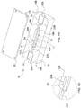
- the heat sink packaging receptacle 19 includes an entry channel 17A and an exit channel 17B.
- the entry channel 17A extends between a first end 19A of the heat sink packaging receptacle 19 and the cavity 24 and is in intimate contact with an input end 30A of the optical fiber component for dissipating heat power and/or optical power from the input end 30A of the optical fiber component 30.
- the exit channel 17B extends between a second end 19B of the heat sink packaging receptacle 19 and the cavity 24, and is in intimate contact with the output end 30B of the optical fiber component 30 for dissipating heat power and/or optical power from the output end of the optical fiber component 30.
- the package 10 may include an adhesive located at an adhesive bond site 14 and 16 proximate the ends 19A and 19B of the heat sink packaging receptacle 19 for affixing the optical fiber component 30 to the heat sink packaging receptacle 19 and preferably distal to the cavity 24 containing the temperature-sensitive portion of the optical fiber component 30.
- the adhesive used is transparent and temperature resistant so as to advantageously dissipate heat from the outer layer (coating/cladding) of the optical fiber component 30 to the heat sink packaging receptacle 19.
- the adhesive may further have a refractive index greater than a refractive index of the cladding/coating of the optical fiber component so as to strip out unwanted optical power from the outer layer (coating/cladding) of the optical fiber component 30.
- the channel(s) 17 provide needed power dissipation at the input and/or output ends 30A and 30B of the optical fiber component 30.
- FIGs. 4A to 8B Several exemplary embodiments of the package according to the present invention are illustrated in FIGs. 4A to 8B and are discussed hereinbelow.
- FIGs. 8A and 8B An optical fiber package according to a first preferred embodiment of the present invention is shown in FIGs. 8A and 8B .
- the package 10 includes a heat sink packaging receptacle 19, which consists of a heat sink substrate 19 and a mating heat sink cover 20, for accommodating an optical fiber component 30.
- Heat sink receptacle 19 serves to protect the optical fiber component 30 from excess heat generated by the component. By having the optical fiber component 30 in direct or indirect contact with the heat sink receptacle 19, excess heat is dissipated away from the component via conduction of heat.
- Heat sink receptacle 19 has a cavity 24 for receiving a temperature-sensitive portion of the optical fiber component 30.
- the package is used to protect an optical fiber component 30 and more specifically a temperature-sensitive portion surrounding optical fiber splice 11 between two optical fibers, 12A and 12B. It should be noted that the portions of optical fibers 12A and 12B immediately adjacent to the splice 11 are left uncoated in this embodiment.
- Cavity 24 is filled with a power-dissipative material 25 that is an optically transparent material having a refractive index lower or equal to a refractive index of a cladding or coating of the optical fibers 12A and 12B (for example, in the case of a typical fiber such as the one shown in FIG.
- the refractive index is lower than or equal to a refractive index of the low index polymer 3 of the pump guide cladding) to ensure that the optical energy, i.e. light, travelling within the optical fibers 12A and 12B remains within the fibers and to attenuate/reduce the amount of heat power generated.
- the section of the optical fiber component 30 located within the cavity 24 is shown in phantom line to illustrate the presence of the power-dissipative material 25.
- the power-dissipative material 25 may be a UV curable low index polymer such as SSCP PC 373 or DSM Desotech Desolite DF0007 or an epoxy such as AngstromBond EX1128.
- the optical fiber component is fixed to the heat sink substrate 18 using adhesive at adhesive bond sites 14 and 16 to affix thereto the coated portions 22A and 22B of the optical fibers 12A and 12B respectively.
- the adhesive used may be an optical epoxy having a high index of refraction, such as Epoxy technology 353ND compound, for example.
- the adhesive bond sites 14 and 16 are placed sufficiently far away from the heat sensitive sections 22A, 12A, 11, 12B, 22B to allow proper heat extraction in the heat sink receptacle 19.
- the power-dissipative material 25 itself could be used to fix the fiber in the heat sink packaging receptacle 19. In such embodiment the adhesive bond sites 14 and 16 need not be present.
- the optical fiber package can also be equipped with active heat sinking (not illustrated) such as, but not limited to, thermo-electric coolers (TEC).
- TEC thermo-electric coolers
- the optical fiber package 10 includes a heat sink receptacle 19, having a heat sink substrate 18 and a mating heat sink cover 20, preferably of good heat conductivity and made of easily machinable materials such as, but not limited to, aluminum or copper.
- the package is used to protect an optical fiber splice 11 (shown in phantom line) between two optical fibers 12A and 12B (shown in phantom line at the location of the splice).
- the fibers 12A and 12B, previously uncoated in the preparation process of optical fiber splice 11, are recoated with a recoat material 13 such as, but not limited to, a UV curable low index polymer.
- a UV curable low index polymer used may be SSCP PC 373 or DSM Desotech Desolite DF0007, for example.
- the optical fibers are fixed to the heat sink 18 at adhesive bond sites 14 and 16 using an adhesive that is preferably both optically transparent and heat resistant.
- the adhesive bond sites are placed sufficiently far away from the heat sensitive sections 22A, 12A, 11, 12B, 22B to allow proper heat extraction in the heat sink 18, for example they are placed at the ends of the channels 17 distal to the cavity 24.
- cavity 24 is filled with a power-dissipative material 25 that is a good heat conductor.
- the heat conducting material may be made of a metal, metallic alloy or any appropriate composite.
- the heat conductor may first be heated beyond its melting point and poured to fill the cavity 24. The heat conductor is then allowed to cool and solidify within the cavity 24.
- the heat conductor is preferably one that has a low melting point, for example gallium, so as to prevent any damage to the temperature sensitive splice 11 from the liquid conductor.
- the optical fiber package 10 a heat sink receptacle 19, having a heat sink substrate 18 a heat sink receptacle 19 for accommodating an optical fiber device component and conducting heat away from the optical fiber device component and a mating heat sink cover 20 for enclosing the optical fiber device within the heat sink receptacle 19.
- Heat sink receptacle 19 has a cavity 24 for receiving a temperature-sensitive component of the optical fiber component 30, and includes an entry channel 17A and an exit channel 17B.
- the entry channel 17A extends between a first end 19A of the heat sink packaging receptacle 19 and the cavity 24 and is in intimate contact with an input end 30A of the optical fiber component for dissipating heat power and/or optical power from the input end 30A of the optical fiber component.
- the exit channel 17B extends between a second end 19B of the heat sink packaging receptacle 19 and the cavity 24, and is in intimate contact with the output end 30B of the optical fiber component 30 for dissipating heat power and/or optical power from the output end of the optical fiber component 30.
- Heat sink substrate 18 and heat sink cover 20 serve to protect the optical fiber device component from excess heat generated by the component by dissipating the excess heat away from the component.
- the heat sinks 18 and 20 are preferably of good heat conductivity and made of easily machinable materials such as, but not limited to, aluminum or copper.
- the heat sink receptacle and cover also serve as mechanical protection for the optical fiber device component.
- the package is used to protect an optical fiber device component 30 and more specifically an optical fiber splice 11 between two optical fibers 12A and 12B. It should be noted that the portions of optical fibers 12A and 12B immediately adjacent to the splice 11 are uncoated.
- the coated portions of the fibers are located in sufficiently long channels 17A and 17B found within heat sink substrate 18, such channels being in intimate contact with the coatings to promote adequate heat exchange between them.
- no part of the fiber's coating 22A and 22B should protrude from the channels of the heat sink 18 into the cavity 24.
- Cavity 24 is filled with air or any heat insensitive gas 25B such as an inert gas e.g. nitrogen.
- the optical fiber component is fixed to the heat sink substrate 18 using adhesive at adhesive bond sites 14 and 16 to fix the coated portions of the optical fibers 12A and 12B at the ends of channels 17A and 17B most distal to the cavity 24.
- the adhesive used may be an optical epoxy such as Epoxy technology 353ND compound, for example.
- the adhesive bond sites 14 and 16 are placed sufficiently far away from the cavity 24 to allow proper heat extraction in the channels 17A and 17B of the heat sink receptacle 19.
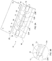
- the optical fiber package 10 includes a heat sink packaging receptacle 19, which has a heat sink substrate 18 and a heat sink cover 20, preferably made of easily machinable good heat conducting materials such as, but not limited to, aluminum or copper.
- the package is used to protect an optical fiber splice 11 between two optical fibers, 12A and 12 B.
- the coated fibers are located in sufficiently long channels 17 within heat sink substrate 18, where the coated fibers are fixed within the channels 17 at the ends of the channels 17 located furthest from the cavity using high refractive index optical adhesive at adhesive bond sites 14 and 16 respectively.
- the high refractive index optical adhesive has a refractive index greater than the refractive index of the polymer coating of the optical fiber and acts as a mode stripper for the optical power propagating in the coating.
- the high refractive index optical adhesive is highly transparent, highly temperature resistant, and of minimal thickness.
- the optical adhesive used may be Epoxy technology #353ND, for example.
- Cavity 24 is filled with air or any heat insensitive gas 25B such as, but not limited to, nitrogen.
- an optical fiber package for removing excess optical power, according to a fifth preferred embodiment of the present invention is shown.
- the optical package may be used to remove, for example, a portion of the light signal and/or amplified spontaneous emission (ASE), and/or the unabsorbed residual pump power.
- the optical fiber package 10 includes a heat sink packaging receptacle 19, which has a heat sink substrate 18 and a heat sink cover 20, preferably made of easily machinable good heat conducting materials such as, but not limited to, aluminum or copper.
- the package 10 is used to remove excess pump power from an optical fiber component 30. In order to remove the excess pump power, a length of the coating is removed from the fiber.
- the uncoated region 12 of the fiber is placed within cavity 24 and the cavity is filled with a power-dissipative material 25, more specifically with a low-temperature melting point heat conductor such as, but not limited to, gallium.
- a power-dissipative material 25 more specifically with a low-temperature melting point heat conductor such as, but not limited to, gallium.
- the section of the optical fiber component 30 located within the cavity 24 is shown in phantom line to illustrate the presence of the power-dissipative material 25.
- the uncoated region 12 could be recoated with a polymer of index of refraction equal to or higher than the pump guide refractive index.
- the polymer used may be DSM Desotech DSM-950-200, for example.
- the heat conductor In order to fill the cavity 24 with the heat conductor, the heat conductor is first heated beyond its melting point and poured in the cavity 24. The heat conductor is then allowed to cool and become solid again. In order to improve the power extraction efficiency from the optical fiber component, the fiber path could also be made curvilinear to introduce bending losses.
- the optical fiber component is fixed to the heat sink substrate 18 using adhesive at adhesive bond sites 14 and 16.
- the method includes the steps of:
- the optical fiber component is inserted into the heat sink substrate of the heat sink packaging receptacle by placing the temperature-sensitive portion within the cavity provided in the heat sink substrate. If the heat sink substrate includes a channel that extends between the cavity and an end of the heat sink substrate, then an end portion of the optical fiber component is inserted within this channel placing it in intimate contact with the channel for dissipating heat power and/or optical power from the end portion of the optical fiber component.
- the optical fiber component maybe positioned such that the cladding of the optical fiber component does not extend into the cavity so as to minimize the amount of excess heat that can enter the cavity. In the case where the temperature sensitive portion of the optical fiber component has had its coating/cladding stripped, i.e. removed, the previously uncoated/decladded section of the temperature-sensitive portion of the optical fiber component may be recoated/recladded prior to inserting the optical fiber component into the heat sink substrate.
- the adhesive is placed at an adhesive bond site proximate an end of the heat sink substrate. If the heat sink substrateis provided with one or more channels, then the adhesive may be placed at an adhesive bond site that is located at the end of the channel most distal to the cavity.
- the adhesive that is used may be optically transparent and temperature resistant. It may also have a refractive index equal to or greater than a refractive index of the cladding/coating of the optical fiber component so as to remove excess power from the cladding/coating of the optical fiber component.
- the corresponding method may also include the step of introducing a power-dissipative material inside the cavity, the power-dissipative material extending within the cavity and surrounding the temperature sensitive portion of the optical fiber component for dissipating heat power and/or optical power therefrom.
- This power-dissipative material may be introduced into the cavity in liquid form and allowed to solidify in place.
- the power-dissipative material has a melting temperature that is low enough so as not to damage the optical fiber component.
- the cavity may be simply be filled with a heat-insensitive gas such as air or inert gas as nitrogen.
- inserting an inert gas is preferably accomplished once the package is assembled. It may be injected into the cavity using a syringe or the packaging may be performed under an inert gas atmosphere to ascertain that the cavity becomes filled the inert gas.
- a heat sink cover is placed in substantially mating relation with the heat sink substrate thereby enclosing the optical fiber component within the package.
- the present invention provides efficient and simple devices to prevent thermal degradation of optical fiber components.
- the present invention allows to dissipate heat power and/or optical power away from a temperature sensitive portion of the optical fiber component.
- the present invention allows for the removal of optical power propagating in a fiber cladding of the optical device component.
- the present invention can reduce the risk of thermal degradation by putting the heat sink in direct contact with the materials subject to excessive heating while displacing the adhesive bonds at a sufficient distance away from critical areas.
- the present application also relates to the following subject-matter:
Landscapes
- Physics & Mathematics (AREA)
- Optics & Photonics (AREA)
- Engineering & Computer Science (AREA)
- Electromagnetism (AREA)
- General Physics & Mathematics (AREA)
- Microelectronics & Electronic Packaging (AREA)
- Plasma & Fusion (AREA)
- Optical Couplings Of Light Guides (AREA)
- Lasers (AREA)
- Mechanical Coupling Of Light Guides (AREA)
- Light Guides In General And Applications Therefor (AREA)
Applications Claiming Priority (2)
| Application Number | Priority Date | Filing Date | Title |
|---|---|---|---|
| US7547308P | 2008-06-25 | 2008-06-25 | |
| EP09768677.8A EP2324379B1 (fr) | 2008-06-25 | 2009-06-25 | Boîtiers de dissipation d'énergie pour un fonctionnement haute puissance de composants de fibre optique |
Related Parent Applications (2)
| Application Number | Title | Priority Date | Filing Date |
|---|---|---|---|
| EP09768677.8A Division EP2324379B1 (fr) | 2008-06-25 | 2009-06-25 | Boîtiers de dissipation d'énergie pour un fonctionnement haute puissance de composants de fibre optique |
| EP09768677.8A Division-Into EP2324379B1 (fr) | 2008-06-25 | 2009-06-25 | Boîtiers de dissipation d'énergie pour un fonctionnement haute puissance de composants de fibre optique |
Publications (2)
| Publication Number | Publication Date |
|---|---|
| EP3086147A1 true EP3086147A1 (fr) | 2016-10-26 |
| EP3086147B1 EP3086147B1 (fr) | 2018-01-24 |
Family
ID=41443950
Family Applications (2)
| Application Number | Title | Priority Date | Filing Date |
|---|---|---|---|
| EP16168378.4A Not-in-force EP3086147B1 (fr) | 2008-06-25 | 2009-06-25 | Boîtiers de dissipation d'énergie pour un fonctionnement haute puissance de composants de fibre optique |
| EP09768677.8A Not-in-force EP2324379B1 (fr) | 2008-06-25 | 2009-06-25 | Boîtiers de dissipation d'énergie pour un fonctionnement haute puissance de composants de fibre optique |
Family Applications After (1)
| Application Number | Title | Priority Date | Filing Date |
|---|---|---|---|
| EP09768677.8A Not-in-force EP2324379B1 (fr) | 2008-06-25 | 2009-06-25 | Boîtiers de dissipation d'énergie pour un fonctionnement haute puissance de composants de fibre optique |
Country Status (6)
| Country | Link |
|---|---|
| US (1) | US8542971B2 (fr) |
| EP (2) | EP3086147B1 (fr) |
| JP (2) | JP2011525706A (fr) |
| CN (2) | CN102124383B (fr) |
| CA (1) | CA2728796C (fr) |
| WO (1) | WO2009155707A1 (fr) |
Cited By (3)
| Publication number | Priority date | Publication date | Assignee | Title |
|---|---|---|---|---|
| CN112217085A (zh) * | 2020-09-25 | 2021-01-12 | 武汉锐科光纤激光技术股份有限公司 | 一种包层光剥模器 |
| CN112987182A (zh) * | 2021-04-25 | 2021-06-18 | 中国工程物理研究院激光聚变研究中心 | 光纤合束器及光纤激光器 |
| DE102020104327A1 (de) | 2020-02-19 | 2021-08-19 | Audi Aktiengesellschaft | Elektronischer Schaltungskreis mit einem Kühlsystem sowie Kühleinheit für das Kühlsystem und Kraftfahrzeug mit einem Schaltungskreis |
Families Citing this family (60)
| Publication number | Priority date | Publication date | Assignee | Title |
|---|---|---|---|---|
| US8611716B2 (en) * | 2009-09-30 | 2013-12-17 | Corning Incorporated | Channeled substrates for integrated optical devices employing optical fibers |
| FI125081B (fi) | 2011-01-11 | 2015-05-29 | Rofin Sinar Laser Gmbh | Kotelo kuituoptiselle komponentille ja menetelmä sen valmistamiseksi |
| JP2012204372A (ja) * | 2011-03-23 | 2012-10-22 | Olympus Corp | 短パルス光源およびレーザ走査顕微鏡システム |
| US10481339B2 (en) | 2011-06-03 | 2019-11-19 | Foro Energy, Inc. | High average power optical fiber cladding mode stripper, methods of making and uses |
| US9110248B2 (en) | 2011-09-30 | 2015-08-18 | Sumitomo Electric Industries, Ltd. | Connector assembly |
| KR101927883B1 (ko) * | 2011-12-19 | 2018-12-11 | 아이피지 포토닉스 코포레이션 | 고전력 금속 클래드 모드 흡수체 |
| FR2997239B1 (fr) | 2012-10-22 | 2016-01-01 | Commissariat Energie Atomique | Procede de fabrication d'un laser a fibre optique, et laser a fibre optique |
| FR2997238B1 (fr) * | 2012-10-22 | 2017-11-17 | Commissariat Energie Atomique | Laser a fibre optique et procede de fabrication d’un laser a fibre optique |
| DE102012222959B4 (de) * | 2012-12-12 | 2015-04-02 | Semikron Elektronik Gmbh & Co. Kg | Leistungsbauelementeinrichtung |
| CN103064154A (zh) * | 2012-12-28 | 2013-04-24 | 清华大学 | 具有冷却功能的光纤耦合器 |
| US9494751B2 (en) * | 2013-01-18 | 2016-11-15 | Optical Engines Inc. | Non-destructive dissipation of excess optical energy |
| US10802209B2 (en) | 2013-01-28 | 2020-10-13 | Lumentum Operations Llc | Cladding light stripper |
| GB2511923B (en) | 2013-01-28 | 2018-10-03 | Lumentum Operations Llc | A cladding light stripper and method of manufacturing |
| US8885993B2 (en) | 2013-03-13 | 2014-11-11 | Institut National D'optique | Dual-index optical pump stripper assembly |
| US9116296B2 (en) * | 2013-08-13 | 2015-08-25 | Gooch And Housego Plc | Optical fiber device having mode stripper thermally protecting structural adhesive |
| WO2015108529A1 (fr) * | 2014-01-17 | 2015-07-23 | Empire Technology Development Llc | Fibres optiques sans gaine |
| JP6010565B2 (ja) | 2014-02-03 | 2016-10-19 | 株式会社フジクラ | 余剰光除去構造及びファイバレーザ |
| US10069271B2 (en) | 2014-06-02 | 2018-09-04 | Nlight, Inc. | Scalable high power fiber laser |
| CN106575850B (zh) * | 2014-07-25 | 2019-06-11 | 三星钻石工业股份有限公司 | 光纤冷却装置和激光振荡器 |
| US10310201B2 (en) | 2014-08-01 | 2019-06-04 | Nlight, Inc. | Back-reflection protection and monitoring in fiber and fiber-delivered lasers |
| US9634462B2 (en) | 2014-10-15 | 2017-04-25 | Nlight, Inc. | Slanted FBG for SRS suppression |
| CN104297841A (zh) * | 2014-11-05 | 2015-01-21 | 中国工程物理研究院激光聚变研究中心 | 双包层光纤包层功率剥离器 |
| CN104345387A (zh) * | 2014-11-05 | 2015-02-11 | 中国工程物理研究院激光聚变研究中心 | 一种双包层光纤包层功率剥除器 |
| WO2016084439A1 (fr) * | 2014-11-26 | 2016-06-02 | オリンパス株式会社 | Endoscope à balayage |
| US9837783B2 (en) | 2015-01-26 | 2017-12-05 | Nlight, Inc. | High-power, single-mode fiber sources |
| CN104678498A (zh) * | 2015-03-09 | 2015-06-03 | 广东高聚激光有限公司 | 准分布式光纤合束器 |
| US10050404B2 (en) | 2015-03-26 | 2018-08-14 | Nlight, Inc. | Fiber source with cascaded gain stages and/or multimode delivery fiber with low splice loss |
| US9551839B2 (en) * | 2015-03-31 | 2017-01-24 | Raytheon Company | Optical component including nanoparticle heat sink |
| CN107924023B (zh) | 2015-07-08 | 2020-12-01 | 恩耐公司 | 具有用于增加的光束参数乘积的中心折射率受抑制的纤维 |
| CN105244740B (zh) * | 2015-10-29 | 2018-08-31 | 中国工程物理研究院激光聚变研究中心 | 用于光纤激光器的光纤冷却装置 |
| CN108367389B (zh) | 2015-11-23 | 2020-07-28 | 恩耐公司 | 激光加工方法和装置 |
| US11179807B2 (en) | 2015-11-23 | 2021-11-23 | Nlight, Inc. | Fine-scale temporal control for laser material processing |
| US20170205579A1 (en) * | 2016-01-14 | 2017-07-20 | Coherent, Inc. | Enclosure for modified optical fiber |
| CN105552700A (zh) * | 2016-01-29 | 2016-05-04 | 深圳市创鑫激光股份有限公司 | 一种光纤激光器的激光输出端 |
| WO2017143587A1 (fr) * | 2016-02-26 | 2017-08-31 | 华为技术有限公司 | Structure d'emballage d'ensemble optique, ensemble optique, module optique et dispositifs et systèmes associés |
| US10073218B2 (en) * | 2016-03-28 | 2018-09-11 | Massachusetts Institute Of Technology | Metalized double-clad optical fiber |
| JP6368734B2 (ja) * | 2016-04-15 | 2018-08-01 | 株式会社フジクラ | 光ファイバ保護構造及び光学要素の製造方法 |
| US10732439B2 (en) | 2016-09-29 | 2020-08-04 | Nlight, Inc. | Fiber-coupled device for varying beam characteristics |
| US10663767B2 (en) | 2016-09-29 | 2020-05-26 | Nlight, Inc. | Adjustable beam characteristics |
| US10730785B2 (en) | 2016-09-29 | 2020-08-04 | Nlight, Inc. | Optical fiber bending mechanisms |
| DE112017004440T5 (de) * | 2016-09-29 | 2019-06-27 | Furukawa Electric Co., Ltd. | Optische Verbindungsstruktur und optisches Modul |
| US9787048B1 (en) | 2016-10-17 | 2017-10-10 | Waymo Llc | Fiber encapsulation mechanism for energy dissipation in a fiber amplifying system |
| WO2018075799A1 (fr) * | 2016-10-20 | 2018-04-26 | Foro Energy, Inc. | Décapant à mode de gainage de fibre optique de puissance moyenne élevée, procédés de fabrication et utilisations |
| CN106872960A (zh) * | 2017-01-10 | 2017-06-20 | 北京航天计量测试技术研究所 | 一种用于线性调频激光测距系统中光纤光路的防护装置 |
| US10288802B2 (en) * | 2017-05-02 | 2019-05-14 | Teraxion | Optical fiber heat dissipation package |
| CN107219596B (zh) * | 2017-08-04 | 2019-04-05 | 青岛海信宽带多媒体技术有限公司 | 一种光学次模块及光模块 |
| CN108562977A (zh) * | 2018-02-12 | 2018-09-21 | 天津欧泰激光科技有限公司 | 一种高功率光纤耦合器封装结构件 |
| JP6623240B2 (ja) * | 2018-02-20 | 2019-12-18 | 株式会社フジクラ | クラッドモードストリッパ及びレーザ装置 |
| US10790633B2 (en) * | 2018-08-15 | 2020-09-29 | The Board Of Trustees Of The Leland Stanford Junior University | Anti-Stokes-fluorescence-cooled fiber-based gain element |
| EP3850408A4 (fr) * | 2018-09-10 | 2022-05-18 | nLIGHT, Inc. | Épissure de fibres optiques encapsulée par un suppresseur de lumière de mode de gaine |
| US11575239B2 (en) | 2018-09-21 | 2023-02-07 | Nlight, Inc. | Optical fiber cladding light stripper |
| JP2020134722A (ja) * | 2019-02-20 | 2020-08-31 | 株式会社フジクラ | 光デバイス及びレーザ装置 |
| JP6836043B2 (ja) * | 2019-07-26 | 2021-02-24 | 株式会社金門光波 | ファイバーレーザー装置 |
| JP2021056276A (ja) * | 2019-09-27 | 2021-04-08 | 株式会社フジクラ | 光デバイス及びレーザ装置 |
| JP7489464B2 (ja) | 2020-07-01 | 2024-05-23 | 株式会社フジクラ | 固定構造、光デバイス、及びレーザ装置 |
| CN112134127B (zh) * | 2020-09-28 | 2022-02-15 | 武汉安扬激光技术股份有限公司 | 一种风冷包层泵浦高功率光纤放大器 |
| CN112776237B (zh) * | 2020-12-28 | 2023-04-21 | 哈尔滨工业大学 | 一种浇注式树脂基分布式光纤传感器封装装置 |
| US11867947B2 (en) * | 2021-04-30 | 2024-01-09 | Corning Research & Development Corporation | Cable assembly having routable splice protectors |
| CN114296176B (zh) * | 2022-01-06 | 2023-09-26 | 上海昊量光电设备有限公司 | 一种悬空式无胶高功率光纤束及其制造方法 |
| CN114640010B (zh) * | 2022-05-20 | 2022-09-13 | 武汉锐科光纤激光技术股份有限公司 | 封装结构和封装模块 |
Citations (6)
| Publication number | Priority date | Publication date | Assignee | Title |
|---|---|---|---|---|
| FR2380559A1 (fr) * | 1977-02-11 | 1978-09-08 | Sumitomo Electric Industries | Procede de liaison de fibres optiques revetues de matiere plastique |
| EP0078049A2 (fr) * | 1981-10-28 | 1983-05-04 | LES CABLES DE LYON Société anonyme dite: | Dispositif de renforcement de la soudure en bout de deux fibres optiques |
| GB2315883A (en) * | 1996-07-30 | 1998-02-11 | Samsung Electronics Co Ltd | Splicing and protecting metal-coated optical fibres |
| JP2002169053A (ja) * | 2000-12-05 | 2002-06-14 | Sumitomo Electric Ind Ltd | 光ファイバ型カプラおよびその製造方法 |
| US6515994B1 (en) | 1998-07-30 | 2003-02-04 | Lucent Technologies Inc. | Method of communication in a communications network and apparatus therefor |
| US20070206909A1 (en) | 2006-01-23 | 2007-09-06 | Alexandre Wetter | Optical fiber component package for high power dissipation |
Family Cites Families (16)
| Publication number | Priority date | Publication date | Assignee | Title |
|---|---|---|---|---|
| GB1433755A (en) * | 1973-09-01 | 1976-04-28 | Plessey Co Ltd | In-line coupling of two lengths of linear optical waveguide elements |
| US5384875A (en) * | 1993-09-23 | 1995-01-24 | Honeywell Inc. | Fiber optic coupler package and packaging method |
| US5479548A (en) * | 1994-05-27 | 1995-12-26 | Honeywell Inc. | Fiber-optic coupler package |
| JPH0980257A (ja) * | 1995-09-13 | 1997-03-28 | Hitachi Cable Ltd | 導波路と光ファイバとの結合方法 |
| US6205280B1 (en) * | 1998-08-25 | 2001-03-20 | Molecular Optoelectronics Corporation | Blockless fiber optic attenuators and attenuation systems employing dispersion controlled polymers |
| US6307871B1 (en) * | 1998-09-11 | 2001-10-23 | Cutting Edge Optronics, Inc. | Laser system using phase change material for thermal control |
| US6597853B2 (en) * | 2000-12-21 | 2003-07-22 | Lucent Technologies Inc. | Device packaging and method |
| US6681073B2 (en) * | 2001-03-19 | 2004-01-20 | Molecular Optoelectronics Corporation | Fiber optic power control systems and methods |
| JP3699363B2 (ja) * | 2001-05-15 | 2005-09-28 | Tdk株式会社 | 光導波路モジュール実装部品 |
| US6865316B1 (en) * | 2002-10-23 | 2005-03-08 | Nlight Photonics Corporation | System and method of operating low coupling efficiency optical source by dissipating cladding modes |
| TWM241691U (en) * | 2003-02-24 | 2004-08-21 | Young Optics Inc | Holding apparatus for a rod |
| US7010204B2 (en) * | 2003-03-04 | 2006-03-07 | Lucent Technologies Inc. | Optical transmission fiber with thermal management for high-power applications |
| US7349596B2 (en) * | 2006-03-16 | 2008-03-25 | Northrop Grumman Corporation | System and method to remove light from cladding |
| JP4776420B2 (ja) * | 2006-03-30 | 2011-09-21 | 古河電気工業株式会社 | 光ファイバ保護体 |
| US7437046B2 (en) * | 2007-02-12 | 2008-10-14 | Furukawa Electric North America, Inc. | Optical fiber configuration for dissipating stray light |
| US8355608B2 (en) * | 2010-04-12 | 2013-01-15 | Lockheed Martin Corporation | Method and apparatus for in-line fiber-cladding-light dissipation |
-
2009
- 2009-06-25 CN CN2009801318860A patent/CN102124383B/zh not_active Expired - Fee Related
- 2009-06-25 EP EP16168378.4A patent/EP3086147B1/fr not_active Not-in-force
- 2009-06-25 JP JP2011515037A patent/JP2011525706A/ja active Pending
- 2009-06-25 US US13/001,335 patent/US8542971B2/en active Active
- 2009-06-25 WO PCT/CA2009/000889 patent/WO2009155707A1/fr active Application Filing
- 2009-06-25 CN CN201310412223.4A patent/CN103531993B/zh not_active Expired - Fee Related
- 2009-06-25 CA CA2728796A patent/CA2728796C/fr not_active Expired - Fee Related
- 2009-06-25 EP EP09768677.8A patent/EP2324379B1/fr not_active Not-in-force
-
2014
- 2014-03-18 JP JP2014055051A patent/JP5865413B2/ja not_active Expired - Fee Related
Patent Citations (7)
| Publication number | Priority date | Publication date | Assignee | Title |
|---|---|---|---|---|
| FR2380559A1 (fr) * | 1977-02-11 | 1978-09-08 | Sumitomo Electric Industries | Procede de liaison de fibres optiques revetues de matiere plastique |
| US4196965A (en) * | 1977-02-11 | 1980-04-08 | Sumitomo Electric Industries, Ltd. | Connecting method of optical fiber with plastic clad |
| EP0078049A2 (fr) * | 1981-10-28 | 1983-05-04 | LES CABLES DE LYON Société anonyme dite: | Dispositif de renforcement de la soudure en bout de deux fibres optiques |
| GB2315883A (en) * | 1996-07-30 | 1998-02-11 | Samsung Electronics Co Ltd | Splicing and protecting metal-coated optical fibres |
| US6515994B1 (en) | 1998-07-30 | 2003-02-04 | Lucent Technologies Inc. | Method of communication in a communications network and apparatus therefor |
| JP2002169053A (ja) * | 2000-12-05 | 2002-06-14 | Sumitomo Electric Ind Ltd | 光ファイバ型カプラおよびその製造方法 |
| US20070206909A1 (en) | 2006-01-23 | 2007-09-06 | Alexandre Wetter | Optical fiber component package for high power dissipation |
Non-Patent Citations (1)
| Title |
|---|
| F. SEGUIN ET AL.: "Tapered fused bundle coupler package for reliable high optical power dissipation, Fiber Lasers III: Technology, Systems, and Applications", PROCEEDINGS OF SPIE, vol. 6102, 2006 |
Cited By (4)
| Publication number | Priority date | Publication date | Assignee | Title |
|---|---|---|---|---|
| DE102020104327A1 (de) | 2020-02-19 | 2021-08-19 | Audi Aktiengesellschaft | Elektronischer Schaltungskreis mit einem Kühlsystem sowie Kühleinheit für das Kühlsystem und Kraftfahrzeug mit einem Schaltungskreis |
| CN112217085A (zh) * | 2020-09-25 | 2021-01-12 | 武汉锐科光纤激光技术股份有限公司 | 一种包层光剥模器 |
| CN112987182A (zh) * | 2021-04-25 | 2021-06-18 | 中国工程物理研究院激光聚变研究中心 | 光纤合束器及光纤激光器 |
| CN112987182B (zh) * | 2021-04-25 | 2021-08-31 | 中国工程物理研究院激光聚变研究中心 | 光纤合束器及光纤激光器 |
Also Published As
| Publication number | Publication date |
|---|---|
| WO2009155707A1 (fr) | 2009-12-30 |
| CN102124383A (zh) | 2011-07-13 |
| JP2014139686A (ja) | 2014-07-31 |
| EP2324379A4 (fr) | 2013-06-26 |
| CA2728796C (fr) | 2017-01-31 |
| EP2324379A1 (fr) | 2011-05-25 |
| CN103531993B (zh) | 2016-05-25 |
| CN102124383B (zh) | 2013-10-16 |
| EP3086147B1 (fr) | 2018-01-24 |
| US8542971B2 (en) | 2013-09-24 |
| CA2728796A1 (fr) | 2009-12-30 |
| JP2011525706A (ja) | 2011-09-22 |
| US20110110625A1 (en) | 2011-05-12 |
| JP5865413B2 (ja) | 2016-02-17 |
| CN103531993A (zh) | 2014-01-22 |
| EP2324379B1 (fr) | 2017-05-03 |
Similar Documents
| Publication | Publication Date | Title |
|---|---|---|
| US8542971B2 (en) | Packages for high power operation of optical fiber components | |
| US7373070B2 (en) | Optical fiber component package for high power dissipation | |
| JP6748036B2 (ja) | 高パワーで熱を分散する光ファイバデバイス | |
| EP0884813B1 (fr) | Système de communication optique comprenant un laser à fibre pompé à travers le gainage | |
| US8665916B2 (en) | Fiber laser | |
| US7787733B2 (en) | Optical fiber configuration for dissipating stray light | |
| US8885993B2 (en) | Dual-index optical pump stripper assembly | |
| US6428217B1 (en) | Apparatus and method for encapsulation of an optical fiber splice | |
| EP2630530A1 (fr) | Composant en fibres optiques sous enveloppe et son procédé de fabrication | |
| US9435945B2 (en) | High power metal clad mode absorber | |
| CN104185931B (zh) | 大功率金属包层模式吸收器 | |
| CA2810351C (fr) | Ensemble extracteur pour pompe optique a deux indices | |
| US20030103753A1 (en) | Device packaging and method | |
| US20030002844A1 (en) | Optical power beam dump | |
| CN211295685U (zh) | 一种光纤包层光去除装置 |
Legal Events
| Date | Code | Title | Description |
|---|---|---|---|
| PUAI | Public reference made under article 153(3) epc to a published international application that has entered the european phase |
Free format text: ORIGINAL CODE: 0009012 |
|
| AC | Divisional application: reference to earlier application |
Ref document number: 2324379 Country of ref document: EP Kind code of ref document: P |
|
| AK | Designated contracting states |
Kind code of ref document: A1 Designated state(s): AT BE BG CH CY CZ DE DK EE ES FI FR GB GR HR HU IE IS IT LI LT LU LV MC MK MT NL NO PL PT RO SE SI SK TR |
|
| 17P | Request for examination filed |
Effective date: 20170425 |
|
| RBV | Designated contracting states (corrected) |
Designated state(s): AT BE BG CH CY CZ DE DK EE ES FI FR GB GR HR HU IE IS IT LI LT LU LV MC MK MT NL NO PL PT RO SE SI SK TR |
|
| RIC1 | Information provided on ipc code assigned before grant |
Ipc: H01L 23/36 20060101ALI20170519BHEP Ipc: G02B 6/00 20060101AFI20170519BHEP Ipc: G02B 6/24 20060101ALI20170519BHEP Ipc: G02B 6/42 20060101ALI20170519BHEP Ipc: H01S 3/042 20060101ALI20170519BHEP Ipc: G02B 6/02 20060101ALI20170519BHEP Ipc: H01S 3/067 20060101ALI20170519BHEP Ipc: G02B 6/14 20060101ALI20170519BHEP Ipc: G02B 6/36 20060101ALI20170519BHEP Ipc: G02B 6/255 20060101ALI20170519BHEP Ipc: H05K 7/20 20060101ALI20170519BHEP |
|
| GRAP | Despatch of communication of intention to grant a patent |
Free format text: ORIGINAL CODE: EPIDOSNIGR1 |
|
| RAP1 | Party data changed (applicant data changed or rights of an application transferred) |
Owner name: CORACTIVE HIGH-TECH INC. |
|
| INTG | Intention to grant announced |
Effective date: 20170822 |
|
| GRAS | Grant fee paid |
Free format text: ORIGINAL CODE: EPIDOSNIGR3 |
|
| GRAA | (expected) grant |
Free format text: ORIGINAL CODE: 0009210 |
|
| AC | Divisional application: reference to earlier application |
Ref document number: 2324379 Country of ref document: EP Kind code of ref document: P |
|
| AK | Designated contracting states |
Kind code of ref document: B1 Designated state(s): AT BE BG CH CY CZ DE DK EE ES FI FR GB GR HR HU IE IS IT LI LT LU LV MC MK MT NL NO PL PT RO SE SI SK TR |
|
| REG | Reference to a national code |
Ref country code: GB Ref legal event code: FG4D |
|
| REG | Reference to a national code |
Ref country code: CH Ref legal event code: EP |
|
| REG | Reference to a national code |
Ref country code: AT Ref legal event code: REF Ref document number: 966097 Country of ref document: AT Kind code of ref document: T Effective date: 20180215 |
|
| REG | Reference to a national code |
Ref country code: IE Ref legal event code: FG4D |
|
| REG | Reference to a national code |
Ref country code: DE Ref legal event code: R096 Ref document number: 602009050623 Country of ref document: DE |
|
| REG | Reference to a national code |
Ref country code: NL Ref legal event code: MP Effective date: 20180124 |
|
| REG | Reference to a national code |
Ref country code: LT Ref legal event code: MG4D |
|
| REG | Reference to a national code |
Ref country code: AT Ref legal event code: MK05 Ref document number: 966097 Country of ref document: AT Kind code of ref document: T Effective date: 20180124 |
|
| REG | Reference to a national code |
Ref country code: FR Ref legal event code: PLFP Year of fee payment: 10 |
|
| PG25 | Lapsed in a contracting state [announced via postgrant information from national office to epo] |
Ref country code: NL Free format text: LAPSE BECAUSE OF FAILURE TO SUBMIT A TRANSLATION OF THE DESCRIPTION OR TO PAY THE FEE WITHIN THE PRESCRIBED TIME-LIMIT Effective date: 20180124 |
|
| PG25 | Lapsed in a contracting state [announced via postgrant information from national office to epo] |
Ref country code: NO Free format text: LAPSE BECAUSE OF FAILURE TO SUBMIT A TRANSLATION OF THE DESCRIPTION OR TO PAY THE FEE WITHIN THE PRESCRIBED TIME-LIMIT Effective date: 20180424 Ref country code: CY Free format text: LAPSE BECAUSE OF FAILURE TO SUBMIT A TRANSLATION OF THE DESCRIPTION OR TO PAY THE FEE WITHIN THE PRESCRIBED TIME-LIMIT Effective date: 20180124 Ref country code: HR Free format text: LAPSE BECAUSE OF FAILURE TO SUBMIT A TRANSLATION OF THE DESCRIPTION OR TO PAY THE FEE WITHIN THE PRESCRIBED TIME-LIMIT Effective date: 20180124 Ref country code: LT Free format text: LAPSE BECAUSE OF FAILURE TO SUBMIT A TRANSLATION OF THE DESCRIPTION OR TO PAY THE FEE WITHIN THE PRESCRIBED TIME-LIMIT Effective date: 20180124 Ref country code: ES Free format text: LAPSE BECAUSE OF FAILURE TO SUBMIT A TRANSLATION OF THE DESCRIPTION OR TO PAY THE FEE WITHIN THE PRESCRIBED TIME-LIMIT Effective date: 20180124 Ref country code: FI Free format text: LAPSE BECAUSE OF FAILURE TO SUBMIT A TRANSLATION OF THE DESCRIPTION OR TO PAY THE FEE WITHIN THE PRESCRIBED TIME-LIMIT Effective date: 20180124 |
|
| PG25 | Lapsed in a contracting state [announced via postgrant information from national office to epo] |
Ref country code: PL Free format text: LAPSE BECAUSE OF FAILURE TO SUBMIT A TRANSLATION OF THE DESCRIPTION OR TO PAY THE FEE WITHIN THE PRESCRIBED TIME-LIMIT Effective date: 20180124 Ref country code: GR Free format text: LAPSE BECAUSE OF FAILURE TO SUBMIT A TRANSLATION OF THE DESCRIPTION OR TO PAY THE FEE WITHIN THE PRESCRIBED TIME-LIMIT Effective date: 20180425 Ref country code: IS Free format text: LAPSE BECAUSE OF FAILURE TO SUBMIT A TRANSLATION OF THE DESCRIPTION OR TO PAY THE FEE WITHIN THE PRESCRIBED TIME-LIMIT Effective date: 20180524 Ref country code: AT Free format text: LAPSE BECAUSE OF FAILURE TO SUBMIT A TRANSLATION OF THE DESCRIPTION OR TO PAY THE FEE WITHIN THE PRESCRIBED TIME-LIMIT Effective date: 20180124 Ref country code: LV Free format text: LAPSE BECAUSE OF FAILURE TO SUBMIT A TRANSLATION OF THE DESCRIPTION OR TO PAY THE FEE WITHIN THE PRESCRIBED TIME-LIMIT Effective date: 20180124 Ref country code: SE Free format text: LAPSE BECAUSE OF FAILURE TO SUBMIT A TRANSLATION OF THE DESCRIPTION OR TO PAY THE FEE WITHIN THE PRESCRIBED TIME-LIMIT Effective date: 20180124 Ref country code: BG Free format text: LAPSE BECAUSE OF FAILURE TO SUBMIT A TRANSLATION OF THE DESCRIPTION OR TO PAY THE FEE WITHIN THE PRESCRIBED TIME-LIMIT Effective date: 20180424 |
|
| REG | Reference to a national code |
Ref country code: DE Ref legal event code: R097 Ref document number: 602009050623 Country of ref document: DE |
|
| PG25 | Lapsed in a contracting state [announced via postgrant information from national office to epo] |
Ref country code: RO Free format text: LAPSE BECAUSE OF FAILURE TO SUBMIT A TRANSLATION OF THE DESCRIPTION OR TO PAY THE FEE WITHIN THE PRESCRIBED TIME-LIMIT Effective date: 20180124 Ref country code: EE Free format text: LAPSE BECAUSE OF FAILURE TO SUBMIT A TRANSLATION OF THE DESCRIPTION OR TO PAY THE FEE WITHIN THE PRESCRIBED TIME-LIMIT Effective date: 20180124 |
|
| PG25 | Lapsed in a contracting state [announced via postgrant information from national office to epo] |
Ref country code: CZ Free format text: LAPSE BECAUSE OF FAILURE TO SUBMIT A TRANSLATION OF THE DESCRIPTION OR TO PAY THE FEE WITHIN THE PRESCRIBED TIME-LIMIT Effective date: 20180124 Ref country code: DK Free format text: LAPSE BECAUSE OF FAILURE TO SUBMIT A TRANSLATION OF THE DESCRIPTION OR TO PAY THE FEE WITHIN THE PRESCRIBED TIME-LIMIT Effective date: 20180124 Ref country code: SK Free format text: LAPSE BECAUSE OF FAILURE TO SUBMIT A TRANSLATION OF THE DESCRIPTION OR TO PAY THE FEE WITHIN THE PRESCRIBED TIME-LIMIT Effective date: 20180124 |
|
| PLBE | No opposition filed within time limit |
Free format text: ORIGINAL CODE: 0009261 |
|
| STAA | Information on the status of an ep patent application or granted ep patent |
Free format text: STATUS: NO OPPOSITION FILED WITHIN TIME LIMIT |
|
| 26N | No opposition filed |
Effective date: 20181025 |
|
| REG | Reference to a national code |
Ref country code: CH Ref legal event code: PL |
|
| PG25 | Lapsed in a contracting state [announced via postgrant information from national office to epo] |
Ref country code: SI Free format text: LAPSE BECAUSE OF FAILURE TO SUBMIT A TRANSLATION OF THE DESCRIPTION OR TO PAY THE FEE WITHIN THE PRESCRIBED TIME-LIMIT Effective date: 20180124 |
|
| REG | Reference to a national code |
Ref country code: BE Ref legal event code: MM Effective date: 20180630 |
|
| REG | Reference to a national code |
Ref country code: IE Ref legal event code: MM4A |
|
| PG25 | Lapsed in a contracting state [announced via postgrant information from national office to epo] |
Ref country code: LU Free format text: LAPSE BECAUSE OF NON-PAYMENT OF DUE FEES Effective date: 20180625 Ref country code: MC Free format text: LAPSE BECAUSE OF FAILURE TO SUBMIT A TRANSLATION OF THE DESCRIPTION OR TO PAY THE FEE WITHIN THE PRESCRIBED TIME-LIMIT Effective date: 20180124 |
|
| PG25 | Lapsed in a contracting state [announced via postgrant information from national office to epo] |
Ref country code: LI Free format text: LAPSE BECAUSE OF NON-PAYMENT OF DUE FEES Effective date: 20180630 Ref country code: CH Free format text: LAPSE BECAUSE OF NON-PAYMENT OF DUE FEES Effective date: 20180630 Ref country code: IE Free format text: LAPSE BECAUSE OF NON-PAYMENT OF DUE FEES Effective date: 20180625 |
|
| PG25 | Lapsed in a contracting state [announced via postgrant information from national office to epo] |
Ref country code: BE Free format text: LAPSE BECAUSE OF NON-PAYMENT OF DUE FEES Effective date: 20180630 |
|
| PG25 | Lapsed in a contracting state [announced via postgrant information from national office to epo] |
Ref country code: MT Free format text: LAPSE BECAUSE OF NON-PAYMENT OF DUE FEES Effective date: 20180625 |
|
| PG25 | Lapsed in a contracting state [announced via postgrant information from national office to epo] |
Ref country code: TR Free format text: LAPSE BECAUSE OF FAILURE TO SUBMIT A TRANSLATION OF THE DESCRIPTION OR TO PAY THE FEE WITHIN THE PRESCRIBED TIME-LIMIT Effective date: 20180124 |
|
| PG25 | Lapsed in a contracting state [announced via postgrant information from national office to epo] |
Ref country code: PT Free format text: LAPSE BECAUSE OF FAILURE TO SUBMIT A TRANSLATION OF THE DESCRIPTION OR TO PAY THE FEE WITHIN THE PRESCRIBED TIME-LIMIT Effective date: 20180124 |
|
| PG25 | Lapsed in a contracting state [announced via postgrant information from national office to epo] |
Ref country code: HU Free format text: LAPSE BECAUSE OF FAILURE TO SUBMIT A TRANSLATION OF THE DESCRIPTION OR TO PAY THE FEE WITHIN THE PRESCRIBED TIME-LIMIT; INVALID AB INITIO Effective date: 20090625 Ref country code: MK Free format text: LAPSE BECAUSE OF NON-PAYMENT OF DUE FEES Effective date: 20180124 |
|
| PGFP | Annual fee paid to national office [announced via postgrant information from national office to epo] |
Ref country code: FR Payment date: 20210622 Year of fee payment: 13 Ref country code: DE Payment date: 20210618 Year of fee payment: 13 Ref country code: IT Payment date: 20210625 Year of fee payment: 13 |
|
| PGFP | Annual fee paid to national office [announced via postgrant information from national office to epo] |
Ref country code: GB Payment date: 20210625 Year of fee payment: 13 |
|
| REG | Reference to a national code |
Ref country code: DE Ref legal event code: R119 Ref document number: 602009050623 Country of ref document: DE |
|
| GBPC | Gb: european patent ceased through non-payment of renewal fee |
Effective date: 20220625 |
|
| PG25 | Lapsed in a contracting state [announced via postgrant information from national office to epo] |
Ref country code: FR Free format text: LAPSE BECAUSE OF NON-PAYMENT OF DUE FEES Effective date: 20220630 |
|
| PG25 | Lapsed in a contracting state [announced via postgrant information from national office to epo] |
Ref country code: GB Free format text: LAPSE BECAUSE OF NON-PAYMENT OF DUE FEES Effective date: 20220625 Ref country code: DE Free format text: LAPSE BECAUSE OF NON-PAYMENT OF DUE FEES Effective date: 20230103 |
|
| PG25 | Lapsed in a contracting state [announced via postgrant information from national office to epo] |
Ref country code: IT Free format text: LAPSE BECAUSE OF NON-PAYMENT OF DUE FEES Effective date: 20220625 |