EP3086056B1 - Accumulator, air conditioning device, and method for manufacturing accumulator - Google Patents
Accumulator, air conditioning device, and method for manufacturing accumulator Download PDFInfo
- Publication number
- EP3086056B1 EP3086056B1 EP14870798.7A EP14870798A EP3086056B1 EP 3086056 B1 EP3086056 B1 EP 3086056B1 EP 14870798 A EP14870798 A EP 14870798A EP 3086056 B1 EP3086056 B1 EP 3086056B1
- Authority
- EP
- European Patent Office
- Prior art keywords
- pressure refrigerant
- tube
- accumulator
- low pressure
- flow path
- Prior art date
- Legal status (The legal status is an assumption and is not a legal conclusion. Google has not performed a legal analysis and makes no representation as to the accuracy of the status listed.)
- Active
Links
Images

Classifications
-
- F—MECHANICAL ENGINEERING; LIGHTING; HEATING; WEAPONS; BLASTING
- F25—REFRIGERATION OR COOLING; COMBINED HEATING AND REFRIGERATION SYSTEMS; HEAT PUMP SYSTEMS; MANUFACTURE OR STORAGE OF ICE; LIQUEFACTION SOLIDIFICATION OF GASES
- F25B—REFRIGERATION MACHINES, PLANTS OR SYSTEMS; COMBINED HEATING AND REFRIGERATION SYSTEMS; HEAT PUMP SYSTEMS
- F25B43/00—Arrangements for separating or purifying gases or liquids; Arrangements for vaporising the residuum of liquid refrigerant, e.g. by heat
- F25B43/006—Accumulators
-
- F—MECHANICAL ENGINEERING; LIGHTING; HEATING; WEAPONS; BLASTING
- F25—REFRIGERATION OR COOLING; COMBINED HEATING AND REFRIGERATION SYSTEMS; HEAT PUMP SYSTEMS; MANUFACTURE OR STORAGE OF ICE; LIQUEFACTION SOLIDIFICATION OF GASES
- F25B—REFRIGERATION MACHINES, PLANTS OR SYSTEMS; COMBINED HEATING AND REFRIGERATION SYSTEMS; HEAT PUMP SYSTEMS
- F25B13/00—Compression machines, plants or systems, with reversible cycle
-
- F—MECHANICAL ENGINEERING; LIGHTING; HEATING; WEAPONS; BLASTING
- F25—REFRIGERATION OR COOLING; COMBINED HEATING AND REFRIGERATION SYSTEMS; HEAT PUMP SYSTEMS; MANUFACTURE OR STORAGE OF ICE; LIQUEFACTION SOLIDIFICATION OF GASES
- F25B—REFRIGERATION MACHINES, PLANTS OR SYSTEMS; COMBINED HEATING AND REFRIGERATION SYSTEMS; HEAT PUMP SYSTEMS
- F25B2313/00—Compression machines, plants or systems with reversible cycle not otherwise provided for
- F25B2313/023—Compression machines, plants or systems with reversible cycle not otherwise provided for using multiple indoor units
- F25B2313/0233—Compression machines, plants or systems with reversible cycle not otherwise provided for using multiple indoor units in parallel arrangements
-
- F—MECHANICAL ENGINEERING; LIGHTING; HEATING; WEAPONS; BLASTING
- F25—REFRIGERATION OR COOLING; COMBINED HEATING AND REFRIGERATION SYSTEMS; HEAT PUMP SYSTEMS; MANUFACTURE OR STORAGE OF ICE; LIQUEFACTION SOLIDIFICATION OF GASES
- F25B—REFRIGERATION MACHINES, PLANTS OR SYSTEMS; COMBINED HEATING AND REFRIGERATION SYSTEMS; HEAT PUMP SYSTEMS
- F25B2313/00—Compression machines, plants or systems with reversible cycle not otherwise provided for
- F25B2313/027—Compression machines, plants or systems with reversible cycle not otherwise provided for characterised by the reversing means
- F25B2313/0272—Compression machines, plants or systems with reversible cycle not otherwise provided for characterised by the reversing means using bridge circuits of one-way valves
-
- F—MECHANICAL ENGINEERING; LIGHTING; HEATING; WEAPONS; BLASTING
- F25—REFRIGERATION OR COOLING; COMBINED HEATING AND REFRIGERATION SYSTEMS; HEAT PUMP SYSTEMS; MANUFACTURE OR STORAGE OF ICE; LIQUEFACTION SOLIDIFICATION OF GASES
- F25B—REFRIGERATION MACHINES, PLANTS OR SYSTEMS; COMBINED HEATING AND REFRIGERATION SYSTEMS; HEAT PUMP SYSTEMS
- F25B2400/00—General features or devices for refrigeration machines, plants or systems, combined heating and refrigeration systems or heat-pump systems, i.e. not limited to a particular subgroup of F25B
- F25B2400/05—Compression system with heat exchange between particular parts of the system
- F25B2400/051—Compression system with heat exchange between particular parts of the system between the accumulator and another part of the cycle
-
- F—MECHANICAL ENGINEERING; LIGHTING; HEATING; WEAPONS; BLASTING
- F25—REFRIGERATION OR COOLING; COMBINED HEATING AND REFRIGERATION SYSTEMS; HEAT PUMP SYSTEMS; MANUFACTURE OR STORAGE OF ICE; LIQUEFACTION SOLIDIFICATION OF GASES
- F25B—REFRIGERATION MACHINES, PLANTS OR SYSTEMS; COMBINED HEATING AND REFRIGERATION SYSTEMS; HEAT PUMP SYSTEMS
- F25B2400/00—General features or devices for refrigeration machines, plants or systems, combined heating and refrigeration systems or heat-pump systems, i.e. not limited to a particular subgroup of F25B
- F25B2400/05—Compression system with heat exchange between particular parts of the system
- F25B2400/054—Compression system with heat exchange between particular parts of the system between the suction tube of the compressor and another part of the cycle
Definitions
- the present invention relates to an accumulator, an air-conditioning apparatus including the accumulator and a method for manufacturing the accumulator.
- a conventional accumulators include a container that seals low pressure refrigerant, a low pressure refrigerant inlet tube that allows the low pressure refrigerant to flow into the container, and a U-shaped tube that allows the low pressure refrigerant in the container to flow out of the container, and the U-shaped tube is covered by an outer tube with a gap between the U-shaped tube and the outer tube. High pressure refrigerant passes through the gap between the U-shaped tube and the outer tube, and the high pressure refrigerant exchanges heat with the low pressure refrigerant in the container and the low pressure refrigerant in the U-shaped tube.
- This heat exchange allows the low pressure refrigerant in the container and the low pressure refrigerant in the U-shaped tube to be gasified and superheated, and the high pressure refrigerant passing through the gap between the U-shaped tube and the outer tube to be subcooled (for example, see Patent Literature 1).
- Patent Literature 1 Japanese Unexamined Patent Application Publication No. 61-83849 (line 14 in the upper left column to line 4 in the lower left column on page 3, and Fig. 1 )
- the present invention has been made in view of these problems, and has an object of providing an accumulator with an improved manufacturing efficiency. Further, the present invention has an object of providing an air-conditioning apparatus having the same accumulator. Further, the present invention has an object of providing an air-conditioning apparatus in which application of the accumulator is embodied. Further, the present invention has an object of providing a method of manufacturing an accumulator with an improved manufacturing efficiency.
- An accumulator according to the present invention has the features of claim 1, and a method for manufacturing an accumulator according to claim 1 has the features of claim 16.
- the first outer tube and the second outer tube communicate with each other via the bridging tube, and thus the low pressure refrigerant turning back section does not need to be covered by the outer tube.
- the gap in forming the turning back section of the low pressure refrigerant outlet body it is not necessary to reliably ensure the gap in forming the turning back section of the low pressure refrigerant outlet body, thereby improving the manufacturing efficiency of the low pressure refrigerant outlet body.
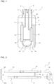
- Figs. 1 to 3 are views and a graph showing the configuration and operation of the accumulator according to Embodiment 1.
- an accumulator 1 includes a container 2, a low pressure refrigerant inlet tube 3, a low pressure refrigerant outlet body 4, a high pressure refrigerant inlet tube 5, and a high pressure refrigerant outlet tube 6.
- the container 2 seals low pressure refrigerant.
- the low pressure refrigerant inlet tube 3 allows low pressure refrigerant to flow into the container 2.
- the low pressure refrigerant outlet body 4 allows low pressure refrigerant to flow out of the container 2.
- the high pressure refrigerant inlet tube 5 allows high pressure refrigerant to flow into the container 2.
- the high pressure refrigerant outlet tube 6 allows high pressure refrigerant to flow out of the container 2.
- the container 2 is preferably made up of a cap 2a and a shell 2b, and the low pressure refrigerant inlet tube 3, the low pressure refrigerant outlet body 4, the high pressure refrigerant inlet tube 5, and the high pressure refrigerant outlet tube 6 are fixed penetrating through through-holes formed in the cap 2a.
- the low pressure refrigerant inlet tube 3, the low pressure refrigerant outlet body 4, the high pressure refrigerant inlet tube 5, and the high pressure refrigerant outlet tube 6 can be mounted in the container 2 while the container 2 is open, and after that, the container 2 can be sealed by a simple operation of joining the cap 2a.
- manufacturing efficiency of the accumulator 1 can be improved.
- the low pressure refrigerant outlet body 4 includes a first tube 11 that extends from an upper position to a lower position in the container 2, a U-shaped tube 12 that is connected to the lower end of the first tube 11 and a second tube 13 having a lower end connected to the U-shaped tube 12. As shown in Fig. 2 , the first tube 11, the U-shaped tube 12, and the second tube 13 are separate members.
- the low pressure refrigerant enters the container 2, flows from the upper end of the first tube 11 to the low pressure refrigerant outlet body 4, passes through the first tube 11, the U-shaped tube 12, and the second tube 13 in this order, and exits the container 2.
- the flow path of the low pressure refrigerant outlet body 4 through which low pressure refrigerant flows is hereinafter referred to as a low pressure refrigerant flow path 4a.
- the U-shaped tube 12 may not be in U-shape and may be a block that forms a U-shaped flow path.
- the first tube 11 corresponds to an "upstream-side tubular section" of the present invention.
- the U-shaped tube 12 corresponds to a "low pressure refrigerant turning back section” of the present invention.
- An area of the second tube 13 that is located in the container 2 corresponds to a "downstream-side tubular section" of the present invention.
- the first tube 11, the U-shaped tube 12, and the second tube 13 of the low pressure refrigerant outlet body 4 may be a unitary member, that is, a unitary U-shaped tube.
- a portion of the unitary U-shaped tube that corresponds to the first tube 11 corresponds to the "upstream-side tubular section" of the present invention.
- a portion of the unitary U-shaped tube that corresponds to the U-shaped tube 12 corresponds to the "low pressure refrigerant turning back section" of the present invention.
- a portion of the unitary U-shaped tube that corresponds to the area of the second tube 13 that is located in the container 2 corresponds to the "downstream-side tubular section" of the present invention.
- the first tube 11, the U-shaped tube 12, and the second tube 13 of the low pressure refrigerant outlet body 4 are formed as separate members, and thus more members (such as the U-shaped tube 12) can be used in common by a plurality of accumulators 1 having different volumes compared with the case where the first tube 11, the U-shaped tube 12, and the second tube 13 are formed as a unitary U-shaped tube, thereby reducing the manufacturing cost. Further, in the case where the first tube 11, the U-shaped tube 12, and the second tube 13 are formed as a unitary U-shaped tube, both ends of the unitary U-shaped tube expand to a certain extent due to a spring effect of the turning back section.
- the first tube 11, the U-shaped tube 12, and the second tube 13 are formed as separate members, expansion between both ends of the U-shaped tube 12 can be easily reduced or eliminated since the U-shaped tube 12 is formed as a separate member, and thus, expansion between the upper end of the first tube 11 and the upper end of the second tube 13 can be prevented.
- a sealing property of low pressure refrigerant in the container 2 can be improved and a productivity in manufacturing of the accumulator 1 can be improved.
- At least a part of the first tube 11 is covered by a first outer tube 14 with a gap between the first tube 11 and the first outer tube 14.
- the first outer tube 14 is connected to the high pressure refrigerant outlet tube 6.
- At least a part of the second tube 13 is covered by a second outer tube 15 with a gap between the second tube 13 and the second outer tube 15.
- the second outer tube 15 is connected to the high pressure refrigerant inlet tube 5.
- the first outer tube 14 and the second outer tube 15 communicate with each other via a bridging tube 16.
- the high pressure refrigerant After the high pressure refrigerant enters the high pressure refrigerant inlet tube 5 into the gap between the second tube 13 and the second outer tube 15, it flows through the bridging tube 16, the gap between the first tube 11 and the first outer tube 14, and the high pressure refrigerant outlet tube 6 in sequence and exits the container 2.
- the flow path of the low pressure refrigerant outlet body 4 through which high pressure refrigerant flows is hereinafter referred to as a high pressure refrigerant flow path 4b.
- the first outer tube 14 and the second outer tube 15 communicate with each other via the bridging tube 16, and thus the U-shaped tube 12 does not need to be covered by an outer tube.
- low pressure refrigerant passing through the container 2 and the low pressure refrigerant flow path 4a exchanges heat with high pressure refrigerant passing through the high pressure refrigerant flow path 4b.
- This heat exchange promotes gasification and superheat of the low pressure refrigerant passing through the container 2 and the low pressure refrigerant flow path 4a so that gas refrigerant that is sufficiently superheated and contains little liquid refrigerant flows out of the low pressure refrigerant outlet body 4, and promotes subcooling of the high pressure refrigerant passing through the high pressure refrigerant flow path 4b so that liquid refrigerant that is sufficiently subcooled flows out of the high pressure refrigerant outlet tube 6.
- low pressure refrigerant passing through the low pressure refrigerant flow path 4a and high pressure refrigerant passing through the high pressure refrigerant flow path 4b flow in mutually opposite directions.
- low pressure refrigerant passing through a downstream-side area of the low pressure refrigerant flow path 4a has a large temperature difference to the high pressure refrigerant
- high pressure refrigerant passing through a downstream-side area of the high pressure refrigerant flow path 4b has a large temperature difference to the low pressure refrigerant.
- This temperature difference improves heat exchange efficiency in the low pressure refrigerant outlet body 4 and further promotes gasification and superheat of the low pressure refrigerant passing through the container 2 and the low pressure refrigerant flow path 4a and subcooling of the high pressure refrigerant passing through the high pressure refrigerant flow path 4b.
- first tube 11, the U-shaped tube 12, and the second tube 13 of the low pressure refrigerant outlet body 4 are formed as separate members, and thus more members (such as the U-shaped tube 12) can be used in common by a low pressure refrigerant outlet body of a type having the first tube 11 and the second tube 13 that are not covered by an outer tube, thereby reducing the manufacturing cost.
- the first outer tube 14 preferably has a length larger than that of the second outer tube 15. With this configuration, gasification of low pressure refrigerant around the first tube 11 is further promoted, and thus liquid refrigerant is reliably prevented from entering the upper end of the first tube 11, and increase of pressure loss generated in the high pressure refrigerant passing through the high pressure refrigerant flow path 4b due to the excessively long high pressure refrigerant flow path 4b can also be prevented.
- the U-shaped tube 12 has an oil return hole 17.
- the oil return hole 17 is located at a lower position in the container 2, particularly, at a lower position relative to the bridging tube 16.
- the oil return hole 17 allows the oil accumulated at the bottom of the container 2, for example, lubricating oil for the compressor to flow into the low pressure refrigerant flow path 4a and to flow out along with the low pressure refrigerant from the accumulator 1.
- the oil return hole 17 is formed in the U-shaped tube 12, which is not covered by an outer tube, and thus manufacturing efficiency of the low pressure refrigerant outlet body 4 can be improved.
- the oil return hole 17 corresponds to an "oil inlet flow path" of the present invention.
- a downstream-side area of the second tube 13 is not covered by the second outer tube 15 and is connected to one end of a straw tube 18.
- the other end (distal end) of the straw tube 18 is located at a lower position in the container 2, particularly, at a lower position relative to the bridging tube 16.
- the straw tube 18 allows the oil accumulated at the bottom of the container 2, for example, lubricating oil for the compressor to be suctioned into the low pressure refrigerant flow path 4a.
- the straw tube 18 is connected to the downstream-side area of the second tube 13 that is not covered by an outer tube, and thus manufacturing efficiency of the low pressure refrigerant outlet body 4 can be improved.
- the straw tube 18 is connected to the area close to an outlet port of the low pressure refrigerant flow path 4a, and thus head difference between both ends of the straw tube 18 increases and suctioning of the oil accumulated at the bottom of the container 2, for example, lubricating oil for the compressor is promoted.
- the straw tube 18 corresponds to the "oil inlet flow path" of the present invention.
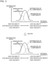
- the bridging tube 16 is located at an upper position relative to the oil return hole 17 and the distal end of the straw tube 18, and thus separation between oil, for example, lubricating oil for the compressor and liquid refrigerant in the container 2 is promoted. That is, as shown in Fig. 3 , oil that flows into the container 2, for example, lubricating oil for the compressor tends to contain oil components having different solubility, and oil components having low solubility are separated from the liquid refrigerant, but oil components having high solubility are solved in the liquid refrigerant and are not separated from the liquid refrigerant.
- the bridging tube 16 is located at a lower position relative to the oil return hole 17 and the distal end of the straw tube 18, the oil accumulated at the bottom of the container 2, for example, lubricating oil for the compressor and liquid refrigerant are heated by the bridging tube 16, thus increasing oil components that are not separated.
- the oil accumulated at the bottom of the container 2 for example, lubricating oil for the compressor and liquid refrigerant are prevented from being heated by the bridging tube 16, and thus oil components that are not separated are prevented from increasing.
- This prevention promotes two-layering of oil in the container 2 of, for example, lubricating oil for the compressor and liquid refrigerant.
- oil returning property of oil in the accumulator 1, for example, lubricating oil for the compressor is improved, thereby further improving reliability of prevention of failure of compressor or other troubles.
- the low pressure refrigerant outlet body 4 may include only one of the oil return hole 17 and the straw tube 18.
- the low pressure refrigerant outlet body 4 includes the oil return hole 17 and the straw tube 18.
- a support member 21 is fixed to the U-shaped tube 12.
- a support member 22 is fixed to the high pressure refrigerant inlet tube 5, which is not shown, the high pressure refrigerant outlet tube 6, which is not shown, the first tube 11, and the second tube 13.
- the support members 21 and 22 have outer peripheral surfaces 21a and 22a that are shaped along an inner peripheral surface of the shell 2b and are attached on the inner peripheral surface of the shell 2b.
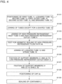
- Fig. 4 is a block diagram showing a method for manufacturing the accumulator according to Embodiment 1.
- the members are positioned so that at least a part of the first tube 11 is covered by the first outer tube 14 with a gap between the first tube 11 and the first outer tube 14, at least a part of the second tube 13 is covered by the second outer tube 15 with a gap between the second tube 13 and the second outer tube 15, the first outer tube 14 and the second outer tube 15 communicate with each other via the bridging tube 16, and the first tube 11 and the second tube 13 communicate with each other via the U-shaped tube 12.
- the tubes except for the U-shaped tube 12 are joined by brazing or other methods.
- the U-shaped tube 12 may be positioned after S102.
- the U-shaped tube 12 corresponds to a "relay member" of the present invention.
- the high pressure refrigerant inlet tube 5 is joined to the second outer tube 15 by brazing or other methods and the high pressure refrigerant outlet tube 6 is joined to the first outer tube 14 by brazing or other methods.
- test for hermetic sealing of the high pressure refrigerant flow path 4b is performed. Through these processes, hermetic sealing property of the high pressure refrigerant flow path 4b through which high pressure refrigerant passes can be reliably achieved compared with the low pressure refrigerant flow path 4a.
- the U-shaped tube 12 and the straw tube 18 are joined by brazing or other methods to form the low pressure refrigerant outlet body 4.
- the support members 21 and 22 are fixed to the low pressure refrigerant outlet body 4.
- the support member 21 is preferably fixed before the U-shaped tube 12 is positioned.
- the low pressure refrigerant outlet body 4 corresponds to a "refrigerant outlet body" of the present invention.
- the inner peripheral surface of the shell 2b and the outer peripheral surfaces 21a and 22a of the support members 21 and 22 are joined by welding or other methods. Then, in S108, the cap 2a having the low pressure refrigerant inlet tube 3 joined thereto in advance is positioned. Then, in S109, the cap 2a is joined to the shell 2b to seal the container 2.
- the first outer tube 14 and the second outer tube 15 may not communicate with each other via the bridging tube 16 as long as at least a part of the low pressure refrigerant flow path 4a is covered by an outer tube. That is, for example, the accumulator 1 may include an outer tube that covers the U-shaped tube 12 with a gap between the U-shaped tube and the outer tube so that the first outer tube 14 and the second outer tube 15 communicates with each other via the outer tube.
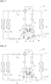
- Figs. 5 and 6 are views showing Usage example-1 of the accumulator according to Embodiment 1.
- a flow of refrigerant during heating operation is indicated by the solid arrow
- a flow of refrigerant during cooling operation is indicated by the dotted arrow.
- a flow path of a four-way valve 62 during heating operation is indicated by the solid line
- a flow path of the four-way valve 62 during cooling operation is indicated by the dotted line.
- the accumulator 1 is applied to an air-conditioning apparatus 50.
- the air-conditioning apparatus 50 includes a refrigerant circuit 51 that connects the accumulator 1, a compressor 61, the four-way valve 62, indoor heat exchangers 63a and 63b, an expansion device 64, and an outdoor heat exchanger 65 by a pipe including extension pipes 66 and 67, and a controller 52 that controls an operation of the refrigerant circuit 51. Only one of the indoor heat exchangers 63a and 63b may be provided.
- the four-way valve 62 may be any other mechanism that can switch a circulation direction of refrigerant discharged from the compressor 61.
- the four-way valve 62 corresponds to a "first flow switching mechanism" of the present invention.
- the expansion device 64 corresponds to a "first expansion device" of the present invention.
- the refrigerant After flowing through the low pressure refrigerant flow path 4a of the accumulator 1, the refrigerant is suctioned into the compressor 61.
- the high pressure refrigerant flow path 4b of the accumulator 1 is connected so that the high pressure refrigerant outlet tube 6 connected to the first outer tube 14 communicates with the expansion device 64, and the high pressure refrigerant inlet tube 5 connected to the second outer tube 15 communicates with the indoor heat exchangers 63a and 63b.
- the controller 52 switches the flow path of the four-way valve 62 as indicated by the solid line shown in Fig. 5 .
- Refrigerant turned into high pressure gas refrigerant in the compressor 61 flows through the four-way valve 62 into the indoor heat exchangers 63a and 63b, is condensed by exchanging heat with indoor air supplied by a fan or other devices, and becomes subcooled liquid refrigerant.
- the subcooled liquid refrigerant flows into the high pressure refrigerant flow path 4b of the accumulator 1, and becomes further subcooled liquid refrigerant by exchanging heat with low pressure refrigerant passing through the low pressure refrigerant flow path 4a of the accumulator 1 and low pressure refrigerant in the container 2 of the accumulator 1.
- the further subcooled liquid refrigerant flows into the expansion device 64, and is expanded in the expansion device 64 and becomes low pressure two-phase gas-liquid refrigerant.
- the low pressure two-phase gas-liquid refrigerant flows into the outdoor heat exchanger 65, and is evaporated by exchanging heat with outside air supplied by a fan or other devices. After flowing through the outdoor heat exchanger 65, the refrigerant flows through the four-way valve 62 into the container 2 of the accumulator 1.
- the refrigerant that flows into the container 2 of the accumulator 1 is superheated or increased in quality by exchanging heat with high pressure refrigerant passing through the high pressure refrigerant flow path 4b of the accumulator 1 while the refrigerant passes through the container 2 and the low pressure refrigerant flow path 4a, becomes sufficiently superheated gas refrigerant that contains little liquid refrigerant, and is again suctioned into the compressor 61.
- the controller 52 switches the flow path of the four-way valve 62 as indicated by the dotted line shown in Fig. 5 .
- Refrigerant turned into high pressure gas refrigerant in the compressor 61 flows through the four-way valve 62 into the outdoor heat exchanger 65, is condensed by exchanging heat with outside air or other mediums supplied by a fan or other devices, and becomes subcooled liquid refrigerant.
- the subcooled liquid refrigerant flows into the expansion device 64, is expanded in the expansion device 64, and becomes low pressure two-phase gas-liquid refrigerant.
- the low pressure two-phase gas-liquid refrigerant flows into the high pressure refrigerant flow path 4b of the accumulator 1, and exchanges heat with low pressure refrigerant passing through the low pressure refrigerant flow path 4a of the accumulator 1 and low pressure refrigerant in the container 2 of the accumulator 1.
- the low pressure refrigerant has been reduced in pressure by a pressure loss generated in the extension pipe 66, the indoor heat exchangers 63a and 63b, and the extension pipe 67. Then, the low pressure two-phase gas-liquid refrigerant flows into the indoor heat exchangers 63a and 63b, and is evaporated by exchanging heat with indoor air supplied by a fan or other devices.
- the refrigerant flows through the four-way valve 62 into the container 2 of the accumulator 1.
- the refrigerant that flows into the container 2 of the accumulator 1 is superheated or increased in quality by exchanging heat with high pressure refrigerant passing through the high pressure refrigerant flow path 4b of the accumulator 1 while the refrigerant passes through the container 2 and the low pressure refrigerant flow path 4a, and becomes sufficiently superheated gas refrigerant that contains little liquid refrigerant, and is again suctioned into the compressor 61.
- the low pressure refrigerant passes through the container 2 and the low pressure refrigerant flow path 4a before being suctioned into the compressor 61, and the high pressure refrigerant flows into the expansion device 64 after passing through the high pressure refrigerant flow path 4b.
- gasification and superheat of the low pressure refrigerant passing through the container 2 and the low pressure refrigerant flow path 4a can be reliably achieved by using the high pressure refrigerant before being expanded in the expansion device 64 that generates a large pressure difference, and thus gas refrigerant that is sufficiently superheated and contains little liquid refrigerant reliably flows out of the low pressure refrigerant outlet body 4.
- the refrigerant circuit 51 is configured to switch heating operation and cooling operation by switching operation of the four-way valve 62.
- subcooling of the high pressure refrigerant passing through the high pressure refrigerant flow path 4b can be reliably achieved by using the low pressure refrigerant before being pressurized in the compressor 61 that generates a large pressure difference, and thus it is possible to reduce the pressure loss generated in the outdoor heat exchanger 65 by decreasing the refrigerant quality on the inlet side of the outdoor heat exchanger 65, although the refrigerant circuit 51 is configured to switch heating operation and cooling operation by switching operation of the four-way valve 62.
- heat exchange efficiency of the outdoor heat exchanger 65 can be improved by enhancing a refrigerant distribution performance of the outdoor heat exchanger 65.
- the low pressure refrigerant passing through the low pressure refrigerant flow path 4a and the high pressure refrigerant passing through the high pressure refrigerant flow path 4b flow in mutually opposite directions.
- gasification and superheat of the low pressure refrigerant passing through the low pressure refrigerant flow path 4a and subcooling of the high pressure refrigerant passing through the high pressure refrigerant flow path 4b can be further reliably achieved.
- the refrigerant circuit 51 is configured to switch heating operation and cooling operation by switching operation of the four-way valve 62.
- the refrigerant circuit 51 performs heating operation
- the high pressure refrigerant that has passed through the high pressure refrigerant flow path 4b flows into the expansion device 64, and the low pressure refrigerant passing through the low pressure refrigerant flow path 4a and the high pressure refrigerant passing through the high pressure refrigerant flow path 4b flow in mutually opposite directions.
- air that exchanges heat with refrigerant in the evaporator tends to have low temperature compared with that during cooling operation, and thus superheat of refrigerant tends to be difficult.
- preferential improvement in heat exchange efficiency in the low pressure refrigerant outlet body 4 during heating operation makes it possible, at a low cost, to prevent failure and decrease in operation efficiency of the compressor 61 and promote reduction in pressure loss generated in the outdoor heat exchanger 65 and improvement of heat exchange efficiency of the outdoor heat exchanger 65.
- the high pressure refrigerant may flow into the expansion device 64 after passing through the high pressure refrigerant flow path 4b, and the low pressure refrigerant passing through the low pressure refrigerant flow path 4a and the high pressure refrigerant passing through the high pressure refrigerant flow path 4b may flow in mutually opposite directions.
- gasification and superheat of the low pressure refrigerant passing through the low pressure refrigerant flow path 4a and subcooling of the high pressure refrigerant passing through the high pressure refrigerant flow path 4b can be reliably achieved.
- the refrigerant circuit 51 is configured to switch heating operation and cooling operation by switching operation of the four-way valve 62.
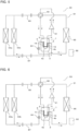
- Figs. 7 and 8 are views showing Usage example-2 of the accumulator according to Embodiment 1.
- a flow of refrigerant during heating operation is indicated by the solid arrow
- a flow of refrigerant during cooling operation is indicated by the dotted arrow.
- a flow path of a four-way valve 62 during heating operation is indicated by the solid line
- a flow path of the four-way valve 62 during cooling operation is indicated by the dotted line.
- the air-conditioning apparatus 50 includes a flow switching mechanism 68.
- the flow switching mechanism 68 corresponds to a "second flow switching mechanism" of the present invention.
- the flow switching mechanism 68 includes a check valve 71, a check valve 72, a check valve 73, and a check valve 74, and operates so that the high pressure refrigerant that has passed through the high pressure refrigerant flow path 4b flows into the expansion device 64 both in a case where the refrigerant circuit 51 performs heating operation and in a case where the refrigerant circuit 51 performs cooling operation.
- the pipe on an upstream-side of the high pressure refrigerant flow path 4b and the pipe on a downstream-side of the expansion device 64 are connected to the flow switching mechanism 68 so that the flow switching mechanism 68 guides the refrigerant that flows out of the indoor heat exchangers 63a and 63b during heating operation to flow into the high pressure refrigerant inlet tube 5 and the refrigerant that flows out of the outdoor heat exchanger 65 during cooling operation to flow into the high pressure refrigerant inlet tube 5.
- the flow switching mechanism 68 may be other mechanism such as a four-way valve.
- the low pressure refrigerant passes through the container 2 and the low pressure refrigerant flow path 4a before being suctioned into the compressor 61, and the high pressure refrigerant flows into the expansion device 64 after passing through the high pressure refrigerant flow path 4b.
- gasification and superheat of the low pressure refrigerant passing through the low pressure refrigerant flow path 4a and subcooling of the high pressure refrigerant passing through the high pressure refrigerant flow path 4b can be reliably achieved.
- the refrigerant circuit 51 is configured to switch heating operation and cooling operation by switching operation of the four-way valve 62.
- the low pressure refrigerant passing through the low pressure refrigerant flow path 4a and the high pressure refrigerant passing through the high pressure refrigerant flow path 4b flow in mutually opposite directions.
- gasification and superheat of the low pressure refrigerant passing through the low pressure refrigerant flow path 4a and subcooling of the high pressure refrigerant passing through the high pressure refrigerant flow path 4b can be further reliably achieved.
- the refrigerant circuit 51 is configured to switch heating operation and cooling operation by switching operation of the four-way valve 62.
- the air-conditioning apparatus 50 may include an expansion device 69 instead of the flow switching mechanism 68.
- the controller 52 controls an opening degree of the expansion device 64 to be almost maximum and controls an opening degree of the expansion device 69, for example, to allow the refrigerant flowing out of the indoor heat exchangers 63a and 63b to have a predetermined degree of subcooling.
- the controller 52 controls the opening degree of the expansion device 69 to be almost maximum and controls an opening degree of the expansion device 64, for example, to allow the refrigerant flowing out of the outdoor heat exchanger 65 to have a predetermined degree of subcooling.
- the expansion device 69 corresponds to a "second expansion device" of the present invention.
- the refrigerant circuit 51 performs heating operation and where the refrigerant circuit 51 performs cooling operation
- the high pressure refrigerant flows into either of the expansion device 69 and the expansion device 64 after passing through the high pressure refrigerant flow path 4b.
- the refrigerant circuit 51 performs heating operation and where the refrigerant circuit 51 performs cooling operation
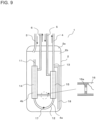
- Fig. 9 is a view showing the configuration and operation of the accumulator according to Embodiment 2.
- the bridging tube 16 includes an aperture 16a therein.
- An opening port area of the aperture 16a that is, the cross sectional area of the flow path is smaller than the cross sectional area of the flow path of the gap between the first tube 11 and the first outer tube 14 and the cross sectional area of the flow path of the gap between the second tube 13 and the second outer tube 15.
- decreasing the wall thickness of the first outer tube 14 or the second outer tube 15 that partially forms the gap on the downstream-side allows for increase in heat transfer efficiency between the high pressure refrigerant passing through the downstream-side gap and having been cooled when the high pressure refrigerant has passed through the upstream-side gap, and the low pressure refrigerant in the container 2, thereby further promoting gasification and superheat of the low pressure refrigerant in the container 2 and subcooling of the high pressure refrigerant passing through the high pressure refrigerant flow path 4b.
- the bridging tube 16 may not include the aperture 16a, and the cross sectional area of the flow path of the bridging tube 16 itself may be smaller than the cross sectional area of the flow path of the gap between the first tube 11 and the first outer tube 14 and the cross sectional area of the flow path of the gap between the second tube 13 and the second outer tube 15. Further, the bridging tube 16 may include a flow control valve instead of the aperture 16a. That is, the cross sectional area of the flow path of at least a part of the bridging tube 16 may be smaller than the cross sectional area of the flow path of the gap between the first tube 11 and the first outer tube 14 and the cross sectional area of the flow path of the gap between the second tube 13 and the second outer tube 15.
- Fig. 10 is a view showing the configuration and operation of the accumulator according to Embodiment 3.
- the bridging tube 16 includes fins 16b.
- heat exchange efficiency of the low pressure refrigerant outlet body 4 can be improved, thereby further promoting gasification and superheat of the low pressure refrigerant in the container 2 and subcooling of the high pressure refrigerant passing through the high pressure refrigerant flow path 4b.
- at least one of the first outer tube 14 and the second outer tube 15 may include fins.
- the first outer tube 14 includes fins, gasification of the low pressure refrigerant around the first tube 11 is promoted, thereby further reliably preventing the liquid refrigerant from entering the upper end of the first tube 11.
- the lower ends of the fins 16b are located at an upper position relative to the oil return hole 17 and the distal end of the straw tube 18.
Landscapes
- Engineering & Computer Science (AREA)
- Physics & Mathematics (AREA)
- Mechanical Engineering (AREA)
- Thermal Sciences (AREA)
- General Engineering & Computer Science (AREA)
- Chemical & Material Sciences (AREA)
- Analytical Chemistry (AREA)
- Power Engineering (AREA)
- Air-Conditioning For Vehicles (AREA)
- Pipe Accessories (AREA)
- Compression-Type Refrigeration Machines With Reversible Cycles (AREA)
- Heat-Exchange Devices With Radiators And Conduit Assemblies (AREA)
Applications Claiming Priority (2)
| Application Number | Priority Date | Filing Date | Title |
|---|---|---|---|
| JP2013262662A JP6184314B2 (ja) | 2013-12-19 | 2013-12-19 | アキュームレータ、及び空気調和装置 |
| PCT/JP2014/076204 WO2015093126A1 (ja) | 2013-12-19 | 2014-09-30 | アキュームレータ、空気調和装置、及び、アキュームレータの製造方法 |
Publications (3)
| Publication Number | Publication Date |
|---|---|
| EP3086056A1 EP3086056A1 (en) | 2016-10-26 |
| EP3086056A4 EP3086056A4 (en) | 2017-07-19 |
| EP3086056B1 true EP3086056B1 (en) | 2024-08-28 |
Family
ID=53402483
Family Applications (1)
| Application Number | Title | Priority Date | Filing Date |
|---|---|---|---|
| EP14870798.7A Active EP3086056B1 (en) | 2013-12-19 | 2014-09-30 | Accumulator, air conditioning device, and method for manufacturing accumulator |
Country Status (7)
| Country | Link |
|---|---|
| US (1) | US10228171B2 (enExample) |
| EP (1) | EP3086056B1 (enExample) |
| JP (1) | JP6184314B2 (enExample) |
| CN (2) | CN104729165B (enExample) |
| AU (1) | AU2014368147B2 (enExample) |
| MX (1) | MX373214B (enExample) |
| WO (1) | WO2015093126A1 (enExample) |
Families Citing this family (11)
| Publication number | Priority date | Publication date | Assignee | Title |
|---|---|---|---|---|
| CN106415153B (zh) * | 2014-06-27 | 2019-04-23 | 三菱电机株式会社 | 制冷循环装置 |
| JP6507071B2 (ja) * | 2015-09-28 | 2019-04-24 | 東芝キヤリア株式会社 | 気液分離器および冷凍サイクル装置 |
| JPWO2017145826A1 (ja) * | 2016-02-24 | 2018-12-13 | Agc株式会社 | 冷凍サイクル装置 |
| CN206207818U (zh) * | 2016-10-31 | 2017-05-31 | 广东美芝精密制造有限公司 | 储液器和具有其的压缩机组件 |
| US10845106B2 (en) * | 2017-12-12 | 2020-11-24 | Rheem Manufacturing Company | Accumulator and oil separator |
| CN111750577B (zh) * | 2019-03-28 | 2022-08-30 | 浙江三花汽车零部件有限公司 | 一种气液分离器 |
| DE102021204471A1 (de) * | 2020-05-05 | 2021-11-11 | Mahle International Gmbh | Kältemittelzwischenspeicher und Kältemittelsystem |
| CN111637655B (zh) * | 2020-07-03 | 2025-09-16 | 聊城新时代新能源设备股份有限公司 | 一种低温补气增焓压缩系统 |
| DE102022118622A1 (de) | 2022-07-26 | 2024-02-01 | Audi Aktiengesellschaft | Kälteanlage für überkritisches Kältemittel mit zusätzlichem Kältemittelspeicher und eingebundenem Wärmeübertrager für ein Kraftfahrzeug, Kraftfahrzeug mit einer solchen Kälteanlage |
| CN116222039B (zh) * | 2023-05-10 | 2023-08-08 | 格兰立方能源科技(江苏)有限公司 | 一种空调用分液储液器及其制冷系统 |
| CN119022521B (zh) * | 2024-10-23 | 2025-02-25 | 珠海凌达压缩机有限公司 | 一种进气管结构、分液器及压缩机 |
Citations (1)
| Publication number | Priority date | Publication date | Assignee | Title |
|---|---|---|---|---|
| JPS6183849A (ja) * | 1984-10-01 | 1986-04-28 | 日新興業株式会社 | ベーパライザの冷媒気化装置 |
Family Cites Families (10)
| Publication number | Priority date | Publication date | Assignee | Title |
|---|---|---|---|---|
| JPS54108454U (enExample) * | 1978-01-18 | 1979-07-31 | ||
| JPS56144279U (enExample) * | 1980-04-01 | 1981-10-30 | ||
| US6681597B1 (en) * | 2002-11-04 | 2004-01-27 | Modine Manufacturing Company | Integrated suction line heat exchanger and accumulator |
| JP2005098581A (ja) * | 2003-09-24 | 2005-04-14 | Hoshizaki Electric Co Ltd | 冷凍回路及び冷凍回路を用いた冷却装置 |
| WO2006005171A1 (en) * | 2004-07-09 | 2006-01-19 | Junjie Gu | Refrigeration system |
| CN1292218C (zh) * | 2005-02-08 | 2006-12-27 | 华南理工大学 | 一种无泵吸收制冷机 |
| JP2006273049A (ja) | 2005-03-28 | 2006-10-12 | Calsonic Kansei Corp | 車両用空調装置 |
| JP4987685B2 (ja) * | 2007-12-19 | 2012-07-25 | 三菱電機株式会社 | 二重管式熱交換器およびその製造方法並びにそれを備えたヒートポンプシステム |
| US8789389B2 (en) * | 2009-10-13 | 2014-07-29 | Showa Denko K.K. | Intermediate heat exchanger |
| JP2011163671A (ja) * | 2010-02-10 | 2011-08-25 | Mitsubishi Electric Corp | 受液器及びそれを用いた冷凍サイクル装置 |
-
2013
- 2013-12-19 JP JP2013262662A patent/JP6184314B2/ja not_active Expired - Fee Related
-
2014
- 2014-09-30 EP EP14870798.7A patent/EP3086056B1/en active Active
- 2014-09-30 WO PCT/JP2014/076204 patent/WO2015093126A1/ja not_active Ceased
- 2014-09-30 MX MX2016008132A patent/MX373214B/es active IP Right Grant
- 2014-09-30 AU AU2014368147A patent/AU2014368147B2/en not_active Ceased
- 2014-09-30 US US15/026,630 patent/US10228171B2/en not_active Expired - Fee Related
- 2014-12-17 CN CN201410785635.7A patent/CN104729165B/zh not_active Expired - Fee Related
- 2014-12-17 CN CN201420802769.0U patent/CN204494925U/zh not_active Expired - Fee Related
Patent Citations (1)
| Publication number | Priority date | Publication date | Assignee | Title |
|---|---|---|---|---|
| JPS6183849A (ja) * | 1984-10-01 | 1986-04-28 | 日新興業株式会社 | ベーパライザの冷媒気化装置 |
Also Published As
| Publication number | Publication date |
|---|---|
| CN104729165B (zh) | 2017-04-12 |
| AU2014368147B2 (en) | 2017-08-03 |
| US20160245563A1 (en) | 2016-08-25 |
| CN104729165A (zh) | 2015-06-24 |
| EP3086056A1 (en) | 2016-10-26 |
| WO2015093126A1 (ja) | 2015-06-25 |
| MX2016008132A (es) | 2016-10-13 |
| US10228171B2 (en) | 2019-03-12 |
| JP2015117915A (ja) | 2015-06-25 |
| CN204494925U (zh) | 2015-07-22 |
| MX373214B (es) | 2020-05-06 |
| JP6184314B2 (ja) | 2017-08-23 |
| EP3086056A4 (en) | 2017-07-19 |
Similar Documents
| Publication | Publication Date | Title |
|---|---|---|
| EP3086056B1 (en) | Accumulator, air conditioning device, and method for manufacturing accumulator | |
| EP2423609B1 (en) | Heat exchanger and air conditioner on which this heat exchanger is mounted | |
| US20080105420A1 (en) | Parallel Flow Heat Exchanger With Crimped Channel Entrance | |
| EP3467404B1 (en) | Laminated header, heat exchanger, and air conditioning device | |
| EP3205968B1 (en) | Heat exchanger and air conditioning device | |
| EP3290851A1 (en) | Layered header, heat exchanger, and air conditioner | |
| WO2018204808A1 (en) | Heat exchanger for heat pump applications | |
| JP2009041798A (ja) | 熱交換器 | |
| CN113544458B (zh) | 气体集管、热交换器以及制冷循环装置 | |
| AU2017444848B2 (en) | Heat exchanger and refrigeration cycle device | |
| JP2006003071A (ja) | 熱交換器 | |
| JP2015121344A (ja) | 熱交換器 | |
| JP6037512B2 (ja) | コネクタ付き熱交換器 | |
| JP2002048433A (ja) | レシーバタンク付き熱交換器 | |
| US11054187B2 (en) | Heat exchanger and method of manufacturing same | |
| HK1117222A (en) | Liquid-vapor separator for a minichannel heat exchanger | |
| EP1726906A1 (en) | Heat exchanger | |
| JP2008145045A (ja) | 熱交換器 | |
| KR20050061003A (ko) | 에어컨 콘덴서 | |
| JPH11270932A (ja) | リキッドタンク付コンデンサ |
Legal Events
| Date | Code | Title | Description |
|---|---|---|---|
| PUAI | Public reference made under article 153(3) epc to a published international application that has entered the european phase |
Free format text: ORIGINAL CODE: 0009012 |
|
| 17P | Request for examination filed |
Effective date: 20160509 |
|
| AK | Designated contracting states |
Kind code of ref document: A1 Designated state(s): AL AT BE BG CH CY CZ DE DK EE ES FI FR GB GR HR HU IE IS IT LI LT LU LV MC MK MT NL NO PL PT RO RS SE SI SK SM TR |
|
| AX | Request for extension of the european patent |
Extension state: BA ME |
|
| DAX | Request for extension of the european patent (deleted) | ||
| A4 | Supplementary search report drawn up and despatched |
Effective date: 20170621 |
|
| RIC1 | Information provided on ipc code assigned before grant |
Ipc: F25B 43/00 20060101AFI20170614BHEP Ipc: F25B 1/00 20060101ALI20170614BHEP Ipc: F25B 40/00 20060101ALI20170614BHEP |
|
| STAA | Information on the status of an ep patent application or granted ep patent |
Free format text: STATUS: EXAMINATION IS IN PROGRESS |
|
| 17Q | First examination report despatched |
Effective date: 20201203 |
|
| GRAP | Despatch of communication of intention to grant a patent |
Free format text: ORIGINAL CODE: EPIDOSNIGR1 |
|
| STAA | Information on the status of an ep patent application or granted ep patent |
Free format text: STATUS: GRANT OF PATENT IS INTENDED |
|
| INTG | Intention to grant announced |
Effective date: 20240510 |
|
| GRAS | Grant fee paid |
Free format text: ORIGINAL CODE: EPIDOSNIGR3 |
|
| GRAA | (expected) grant |
Free format text: ORIGINAL CODE: 0009210 |
|
| STAA | Information on the status of an ep patent application or granted ep patent |
Free format text: STATUS: THE PATENT HAS BEEN GRANTED |
|
| AK | Designated contracting states |
Kind code of ref document: B1 Designated state(s): AL AT BE BG CH CY CZ DE DK EE ES FI FR GB GR HR HU IE IS IT LI LT LU LV MC MK MT NL NO PL PT RO RS SE SI SK SM TR |
|
| REG | Reference to a national code |
Ref country code: GB Ref legal event code: FG4D |
|
| REG | Reference to a national code |
Ref country code: CH Ref legal event code: EP |
|
| REG | Reference to a national code |
Ref country code: DE Ref legal event code: R096 Ref document number: 602014090779 Country of ref document: DE |
|
| REG | Reference to a national code |
Ref country code: IE Ref legal event code: FG4D |
|
| REG | Reference to a national code |
Ref country code: LT Ref legal event code: MG9D |
|
| PG25 | Lapsed in a contracting state [announced via postgrant information from national office to epo] |
Ref country code: NO Free format text: LAPSE BECAUSE OF FAILURE TO SUBMIT A TRANSLATION OF THE DESCRIPTION OR TO PAY THE FEE WITHIN THE PRESCRIBED TIME-LIMIT Effective date: 20241128 |
|
| REG | Reference to a national code |
Ref country code: AT Ref legal event code: MK05 Ref document number: 1718336 Country of ref document: AT Kind code of ref document: T Effective date: 20240828 |
|
| PG25 | Lapsed in a contracting state [announced via postgrant information from national office to epo] |
Ref country code: NL Free format text: LAPSE BECAUSE OF FAILURE TO SUBMIT A TRANSLATION OF THE DESCRIPTION OR TO PAY THE FEE WITHIN THE PRESCRIBED TIME-LIMIT Effective date: 20240828 Ref country code: GR Free format text: LAPSE BECAUSE OF FAILURE TO SUBMIT A TRANSLATION OF THE DESCRIPTION OR TO PAY THE FEE WITHIN THE PRESCRIBED TIME-LIMIT Effective date: 20241129 Ref country code: PT Free format text: LAPSE BECAUSE OF FAILURE TO SUBMIT A TRANSLATION OF THE DESCRIPTION OR TO PAY THE FEE WITHIN THE PRESCRIBED TIME-LIMIT Effective date: 20241230 Ref country code: PL Free format text: LAPSE BECAUSE OF FAILURE TO SUBMIT A TRANSLATION OF THE DESCRIPTION OR TO PAY THE FEE WITHIN THE PRESCRIBED TIME-LIMIT Effective date: 20240828 Ref country code: FI Free format text: LAPSE BECAUSE OF FAILURE TO SUBMIT A TRANSLATION OF THE DESCRIPTION OR TO PAY THE FEE WITHIN THE PRESCRIBED TIME-LIMIT Effective date: 20240828 |
|
| PG25 | Lapsed in a contracting state [announced via postgrant information from national office to epo] |
Ref country code: BG Free format text: LAPSE BECAUSE OF FAILURE TO SUBMIT A TRANSLATION OF THE DESCRIPTION OR TO PAY THE FEE WITHIN THE PRESCRIBED TIME-LIMIT Effective date: 20240828 |
|
| PG25 | Lapsed in a contracting state [announced via postgrant information from national office to epo] |
Ref country code: LV Free format text: LAPSE BECAUSE OF FAILURE TO SUBMIT A TRANSLATION OF THE DESCRIPTION OR TO PAY THE FEE WITHIN THE PRESCRIBED TIME-LIMIT Effective date: 20240828 |
|
| REG | Reference to a national code |
Ref country code: NL Ref legal event code: MP Effective date: 20240828 |
|
| PG25 | Lapsed in a contracting state [announced via postgrant information from national office to epo] |
Ref country code: IS Free format text: LAPSE BECAUSE OF FAILURE TO SUBMIT A TRANSLATION OF THE DESCRIPTION OR TO PAY THE FEE WITHIN THE PRESCRIBED TIME-LIMIT Effective date: 20241228 Ref country code: AT Free format text: LAPSE BECAUSE OF FAILURE TO SUBMIT A TRANSLATION OF THE DESCRIPTION OR TO PAY THE FEE WITHIN THE PRESCRIBED TIME-LIMIT Effective date: 20240828 |
|
| PG25 | Lapsed in a contracting state [announced via postgrant information from national office to epo] |
Ref country code: HR Free format text: LAPSE BECAUSE OF FAILURE TO SUBMIT A TRANSLATION OF THE DESCRIPTION OR TO PAY THE FEE WITHIN THE PRESCRIBED TIME-LIMIT Effective date: 20240828 |
|
| PG25 | Lapsed in a contracting state [announced via postgrant information from national office to epo] |
Ref country code: ES Free format text: LAPSE BECAUSE OF FAILURE TO SUBMIT A TRANSLATION OF THE DESCRIPTION OR TO PAY THE FEE WITHIN THE PRESCRIBED TIME-LIMIT Effective date: 20240828 Ref country code: RS Free format text: LAPSE BECAUSE OF FAILURE TO SUBMIT A TRANSLATION OF THE DESCRIPTION OR TO PAY THE FEE WITHIN THE PRESCRIBED TIME-LIMIT Effective date: 20241128 |
|
| PG25 | Lapsed in a contracting state [announced via postgrant information from national office to epo] |
Ref country code: RS Free format text: LAPSE BECAUSE OF FAILURE TO SUBMIT A TRANSLATION OF THE DESCRIPTION OR TO PAY THE FEE WITHIN THE PRESCRIBED TIME-LIMIT Effective date: 20241128 Ref country code: PT Free format text: LAPSE BECAUSE OF FAILURE TO SUBMIT A TRANSLATION OF THE DESCRIPTION OR TO PAY THE FEE WITHIN THE PRESCRIBED TIME-LIMIT Effective date: 20241230 Ref country code: PL Free format text: LAPSE BECAUSE OF FAILURE TO SUBMIT A TRANSLATION OF THE DESCRIPTION OR TO PAY THE FEE WITHIN THE PRESCRIBED TIME-LIMIT Effective date: 20240828 Ref country code: NO Free format text: LAPSE BECAUSE OF FAILURE TO SUBMIT A TRANSLATION OF THE DESCRIPTION OR TO PAY THE FEE WITHIN THE PRESCRIBED TIME-LIMIT Effective date: 20241128 Ref country code: NL Free format text: LAPSE BECAUSE OF FAILURE TO SUBMIT A TRANSLATION OF THE DESCRIPTION OR TO PAY THE FEE WITHIN THE PRESCRIBED TIME-LIMIT Effective date: 20240828 Ref country code: LV Free format text: LAPSE BECAUSE OF FAILURE TO SUBMIT A TRANSLATION OF THE DESCRIPTION OR TO PAY THE FEE WITHIN THE PRESCRIBED TIME-LIMIT Effective date: 20240828 Ref country code: IS Free format text: LAPSE BECAUSE OF FAILURE TO SUBMIT A TRANSLATION OF THE DESCRIPTION OR TO PAY THE FEE WITHIN THE PRESCRIBED TIME-LIMIT Effective date: 20241228 Ref country code: HR Free format text: LAPSE BECAUSE OF FAILURE TO SUBMIT A TRANSLATION OF THE DESCRIPTION OR TO PAY THE FEE WITHIN THE PRESCRIBED TIME-LIMIT Effective date: 20240828 Ref country code: GR Free format text: LAPSE BECAUSE OF FAILURE TO SUBMIT A TRANSLATION OF THE DESCRIPTION OR TO PAY THE FEE WITHIN THE PRESCRIBED TIME-LIMIT Effective date: 20241129 Ref country code: FI Free format text: LAPSE BECAUSE OF FAILURE TO SUBMIT A TRANSLATION OF THE DESCRIPTION OR TO PAY THE FEE WITHIN THE PRESCRIBED TIME-LIMIT Effective date: 20240828 Ref country code: ES Free format text: LAPSE BECAUSE OF FAILURE TO SUBMIT A TRANSLATION OF THE DESCRIPTION OR TO PAY THE FEE WITHIN THE PRESCRIBED TIME-LIMIT Effective date: 20240828 Ref country code: BG Free format text: LAPSE BECAUSE OF FAILURE TO SUBMIT A TRANSLATION OF THE DESCRIPTION OR TO PAY THE FEE WITHIN THE PRESCRIBED TIME-LIMIT Effective date: 20240828 Ref country code: AT Free format text: LAPSE BECAUSE OF FAILURE TO SUBMIT A TRANSLATION OF THE DESCRIPTION OR TO PAY THE FEE WITHIN THE PRESCRIBED TIME-LIMIT Effective date: 20240828 |
|
| PG25 | Lapsed in a contracting state [announced via postgrant information from national office to epo] |
Ref country code: RO Free format text: LAPSE BECAUSE OF FAILURE TO SUBMIT A TRANSLATION OF THE DESCRIPTION OR TO PAY THE FEE WITHIN THE PRESCRIBED TIME-LIMIT Effective date: 20240828 Ref country code: SM Free format text: LAPSE BECAUSE OF FAILURE TO SUBMIT A TRANSLATION OF THE DESCRIPTION OR TO PAY THE FEE WITHIN THE PRESCRIBED TIME-LIMIT Effective date: 20240828 Ref country code: DK Free format text: LAPSE BECAUSE OF FAILURE TO SUBMIT A TRANSLATION OF THE DESCRIPTION OR TO PAY THE FEE WITHIN THE PRESCRIBED TIME-LIMIT Effective date: 20240828 |
|
| PG25 | Lapsed in a contracting state [announced via postgrant information from national office to epo] |
Ref country code: EE Free format text: LAPSE BECAUSE OF FAILURE TO SUBMIT A TRANSLATION OF THE DESCRIPTION OR TO PAY THE FEE WITHIN THE PRESCRIBED TIME-LIMIT Effective date: 20240828 |
|
| PG25 | Lapsed in a contracting state [announced via postgrant information from national office to epo] |
Ref country code: CZ Free format text: LAPSE BECAUSE OF FAILURE TO SUBMIT A TRANSLATION OF THE DESCRIPTION OR TO PAY THE FEE WITHIN THE PRESCRIBED TIME-LIMIT Effective date: 20240828 |
|
| PG25 | Lapsed in a contracting state [announced via postgrant information from national office to epo] |
Ref country code: SK Free format text: LAPSE BECAUSE OF FAILURE TO SUBMIT A TRANSLATION OF THE DESCRIPTION OR TO PAY THE FEE WITHIN THE PRESCRIBED TIME-LIMIT Effective date: 20240828 Ref country code: IT Free format text: LAPSE BECAUSE OF FAILURE TO SUBMIT A TRANSLATION OF THE DESCRIPTION OR TO PAY THE FEE WITHIN THE PRESCRIBED TIME-LIMIT Effective date: 20240828 |
|
| REG | Reference to a national code |
Ref country code: CH Ref legal event code: PL |
|
| PG25 | Lapsed in a contracting state [announced via postgrant information from national office to epo] |
Ref country code: LU Free format text: LAPSE BECAUSE OF NON-PAYMENT OF DUE FEES Effective date: 20240930 |
|
| REG | Reference to a national code |
Ref country code: DE Ref legal event code: R097 Ref document number: 602014090779 Country of ref document: DE |
|
| PLBE | No opposition filed within time limit |
Free format text: ORIGINAL CODE: 0009261 |
|
| STAA | Information on the status of an ep patent application or granted ep patent |
Free format text: STATUS: NO OPPOSITION FILED WITHIN TIME LIMIT |
|
| PG25 | Lapsed in a contracting state [announced via postgrant information from national office to epo] |
Ref country code: MC Free format text: LAPSE BECAUSE OF FAILURE TO SUBMIT A TRANSLATION OF THE DESCRIPTION OR TO PAY THE FEE WITHIN THE PRESCRIBED TIME-LIMIT Effective date: 20240828 |
|
| REG | Reference to a national code |
Ref country code: BE Ref legal event code: MM Effective date: 20240930 |
|
| PG25 | Lapsed in a contracting state [announced via postgrant information from national office to epo] |
Ref country code: BE Free format text: LAPSE BECAUSE OF NON-PAYMENT OF DUE FEES Effective date: 20240930 |
|
| PG25 | Lapsed in a contracting state [announced via postgrant information from national office to epo] |
Ref country code: FR Free format text: LAPSE BECAUSE OF NON-PAYMENT OF DUE FEES Effective date: 20241028 |
|
| GBPC | Gb: european patent ceased through non-payment of renewal fee |
Effective date: 20241128 |
|
| PG25 | Lapsed in a contracting state [announced via postgrant information from national office to epo] |
Ref country code: CH Free format text: LAPSE BECAUSE OF NON-PAYMENT OF DUE FEES Effective date: 20240930 |
|
| PG25 | Lapsed in a contracting state [announced via postgrant information from national office to epo] |
Ref country code: IE Free format text: LAPSE BECAUSE OF NON-PAYMENT OF DUE FEES Effective date: 20240930 |
|
| 26N | No opposition filed |
Effective date: 20250530 |
|
| PG25 | Lapsed in a contracting state [announced via postgrant information from national office to epo] |
Ref country code: SE Free format text: LAPSE BECAUSE OF FAILURE TO SUBMIT A TRANSLATION OF THE DESCRIPTION OR TO PAY THE FEE WITHIN THE PRESCRIBED TIME-LIMIT Effective date: 20240828 |
|
| P01 | Opt-out of the competence of the unified patent court (upc) registered |
Free format text: CASE NUMBER: UPC_APP_4857_3086056/2025 Effective date: 20250827 |
|
| PGFP | Annual fee paid to national office [announced via postgrant information from national office to epo] |
Ref country code: DE Payment date: 20250805 Year of fee payment: 12 |
|
| PG25 | Lapsed in a contracting state [announced via postgrant information from national office to epo] |
Ref country code: GB Free format text: LAPSE BECAUSE OF NON-PAYMENT OF DUE FEES Effective date: 20241128 |