EP3085500B1 - Steuerungsverfahren für elektrisches greifersystem - Google Patents
Steuerungsverfahren für elektrisches greifersystem Download PDFInfo
- Publication number
- EP3085500B1 EP3085500B1 EP15165052.0A EP15165052A EP3085500B1 EP 3085500 B1 EP3085500 B1 EP 3085500B1 EP 15165052 A EP15165052 A EP 15165052A EP 3085500 B1 EP3085500 B1 EP 3085500B1
- Authority
- EP
- European Patent Office
- Prior art keywords
- segment
- gripper mechanism
- control
- driving
- absolute
- Prior art date
- Legal status (The legal status is an assumption and is not a legal conclusion. Google has not performed a legal analysis and makes no representation as to the accuracy of the status listed.)
- Active
Links
Images



Classifications
-
- B—PERFORMING OPERATIONS; TRANSPORTING
- B25—HAND TOOLS; PORTABLE POWER-DRIVEN TOOLS; MANIPULATORS
- B25J—MANIPULATORS; CHAMBERS PROVIDED WITH MANIPULATION DEVICES
- B25J9/00—Program-controlled manipulators
- B25J9/16—Program controls
- B25J9/1612—Program controls characterised by the hand, wrist, grip control
-
- G—PHYSICS
- G05—CONTROLLING; REGULATING
- G05B—CONTROL OR REGULATING SYSTEMS IN GENERAL; FUNCTIONAL ELEMENTS OF SUCH SYSTEMS; MONITORING OR TESTING ARRANGEMENTS FOR SUCH SYSTEMS OR ELEMENTS
- G05B19/00—Program-control systems
- G05B19/02—Program-control systems electric
- G05B19/18—Numerical control [NC], i.e. automatically operating machines, in particular machine tools, e.g. in a manufacturing environment, so as to execute positioning, movement or co-ordinated operations by means of program data in numerical form
- G05B19/19—Numerical control [NC], i.e. automatically operating machines, in particular machine tools, e.g. in a manufacturing environment, so as to execute positioning, movement or co-ordinated operations by means of program data in numerical form characterised by positioning or contouring control systems, e.g. to control position from one programmed point to another or to control movement along a programmed continuous path
- G05B19/27—Numerical control [NC], i.e. automatically operating machines, in particular machine tools, e.g. in a manufacturing environment, so as to execute positioning, movement or co-ordinated operations by means of program data in numerical form characterised by positioning or contouring control systems, e.g. to control position from one programmed point to another or to control movement along a programmed continuous path using an absolute digital measuring device
- G05B19/29—Numerical control [NC], i.e. automatically operating machines, in particular machine tools, e.g. in a manufacturing environment, so as to execute positioning, movement or co-ordinated operations by means of program data in numerical form characterised by positioning or contouring control systems, e.g. to control position from one programmed point to another or to control movement along a programmed continuous path using an absolute digital measuring device for point-to-point control
-
- G—PHYSICS
- G05—CONTROLLING; REGULATING
- G05B—CONTROL OR REGULATING SYSTEMS IN GENERAL; FUNCTIONAL ELEMENTS OF SUCH SYSTEMS; MONITORING OR TESTING ARRANGEMENTS FOR SUCH SYSTEMS OR ELEMENTS
- G05B2219/00—Program-control systems
- G05B2219/30—Nc systems
- G05B2219/42—Servomotor, servo controller kind till VSS
- G05B2219/42204—Absolute positions
-
- G—PHYSICS
- G05—CONTROLLING; REGULATING
- G05B—CONTROL OR REGULATING SYSTEMS IN GENERAL; FUNCTIONAL ELEMENTS OF SUCH SYSTEMS; MONITORING OR TESTING ARRANGEMENTS FOR SUCH SYSTEMS OR ELEMENTS
- G05B2219/00—Program-control systems
- G05B2219/30—Nc systems
- G05B2219/42—Servomotor, servo controller kind till VSS
- G05B2219/42249—Relative positioning
Definitions
- the present invention relates to a control method for an electric gripper system and is applicable to an electric gripper for improving the gripper mechanism in terms of positioning accuracy.
- Electric grippers have been extensively used in automated industry for gripping workpieces to be assembled. However, the existing electric gripper tends to have a minor positional deviation from the targeted site every time it moves. Such positional deviation can continuously accumulate. Over time, the electric gripper the difference between the actually reached site and the targeted site can become significant.
- the workpiece it holds can leave its intended route and collide with the workpieces on which it is to be assembled.
- This prior-art device has a first axis for generating a control command that drives a step motor, and a second axis for generating a correct position.
- the second axis generates a velocity-curve compensation value according to the position of the motor fed back to it, and then generates a composite command for the step motor by computing the velocity curve compensation value and the control command originally generated by the first axis, thereby compensating the positional deviation of the step motor.
- US 5048063 A addresses the problem of cumulative positioning errors in a servo system in a CNC machine tool.
- EP1645374 A2 discloses a control method for accurately gripping with a gripping hand.
- the primary objective of the present invention is to provide a control method that prevents an electric gripper from generating cumulative positional deviation, thereby ensuring that the electric gripper can accurately move to a targeted position.
- the motor according to the driving datum uses a proper rotation rate to control the gripper mechanism to move toward the target position, so as to compensate the positional deviation generated by the gripper mechanism, thereby improving the gripper mechanism in terms of positioning accuracy.
- an electric gripper system serves to drive a gripper mechanism 100 to perform displacement.
- the electric gripper system comprises a motor 10, a sensor 20, and a control processing unit 30.
- the motor 10 serves to drive the gripper mechanism 100 to perform displacement.
- the sensor 20 is assembled onto the motor 10.
- the sensor 20 generates a current position P3 of the gripper mechanism 100 according to the position of the gripper mechanism 100.
- the control processing unit 30 comprises a transceiver segment 32, an accessible segment 34, a control segment 36, and a driving segment 38.
- the control segment 36 is connected to the transceiver segment 32, the accessible segment 34, the driving segment 38, and the sensor 20.
- the transceiver segment 32 generates a relative-position command value C1.
- the accessible segment 34 stores an absolute cumulative position P1.
- the relative-position command value C1 directs the motor 10 to drive the gripper mechanism 100 to move under a relative position mode.
- the control segment 36 reads the relative-position command value C1, the absolute cumulative position P1, and the current position P3.
- the control segment 36 generates a target position P2 based on the relative-position command value C1 and the absolute cumulative position P1.
- the control segment 36 uses a distance between the current position P3 and the target position P2, and uses the rotation rate of the motor 10 (deceleration or acceleration) to generate a driving datum S1.
- the driving datum S1 is a velocity curve.
- the driving segment 38 reads the velocity curve, and converts the acceleration curve into an electric signal (i.e. a current or a voltage), so as to drive the motor 10 to move the gripper mechanism 100.
- an electric signal i.e. a current or a voltage
- FIG. 2 and FIG. 3 Please refer to FIG. 2 and FIG. 3 .
- a control method for the system is described below as a series of steps.
- Step S10 the control segment 36 receives the relative-position command value C1 from the transceiver segment 32. Then in Step S12, the control segment 36 obtains the absolute cumulative position P1 from the accessible segment 34. In Step S13, the control segment 36 adds the relative-position command value C1 and the absolute cumulative position P1 together to generate a target position P2.
- the absolute cumulative position P1 is the current position P3 of the gripper mechanism 100 in an ideal situation.
- the relative-position command value C1 is the distance for the gripper mechanism 100 to move.
- the absolute cumulative position P1 is the current position P3 of the gripper mechanism 100 in an ideal situation, and the initial state of the absolute cumulative position P1 is default.
- Step S20 is about updating the absolute cumulative position P1.
- the sum of the relative-position command value C1 and the absolute cumulative position P1 that is previously stored in the accessible segment 34 is the target positon P2, which is used to replace the absolute cumulative position P1 previously stored in the accessible segment 34.
- the new absolute cumulative position P1 is the current position P3 of the gripper mechanism 100 in an ideal situation.
- the ideal current position P3 is a position reached by the gripper mechanism 100 that moves without any distance deviation.
- Step S14 the control segment 36 receives the current position P3 generated by the sensor 20.
- Step S15 the control segment 36 calculates the difference between the current position P3 and the target position P2, as well as the rotation rate of the motor 10, so as to generate the driving datum S1.
- the positional deviation generated in the previous movement of the gripper mechanism 100 can be compensated, thereby allowing the gripper mechanism 100 to accurately arrive at the target position P2.
- Step S16 the control segment 36 sends the driving datum S1 to the driving segment 38.
- the driving motor 10 drives the gripper mechanism 100 to move toward the target position P2.
- Step S17 the control segment 36 determines whether the motor 10 has entered a positioning range.
- the positioning of the motor 10 is finished (i.e. Step S18).
- the method returns to Step S14, where the control segment 36 re-obtains the current position P3 of the motor 10, and Step S14 through Step S17 are circulatively repeated, until the motor 10 has entered the positioning range.
- the positioning range is the specification tolerance of the workpiece.
- the gripper mechanism 100 During the movement of the gripper mechanism 100, it can move to the target position P2 under either an absolute position mode or a relative position mode.
- the gripper mechanism 100 is switched between the moving modes.
- absolute position mode As how to switch the gripper mechanism 100 absolute position mode is known to people skilled in the art and is not a feature of the present invention, no detailed description is provided thereto in this specification.
- the gripper mechanism 100 has two modes of movement, namely relative position movement and absolute position movement.
- the absolute position movement and the absolute position mode are the same mode.
- the relative position movement and the relative positon mode are the same mode. While relative position movement is about making the gripper mechanism 100 move for a fixed distance and arrive at the target position P2, absolute position movement is about making the gripper mechanism 100 move to the target position P2.
- the command direct the gripper mechanism 100 to move 2mm forward, and if the gripper mechanism 100 moves with an absolute position command, the command direct the gripper mechanism 100 to move to the position 3mm far from the origin.
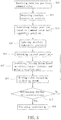
- FIG. 4 is a flowchart of how the absolute cumulative position is updated.
- the control segment 36 first determines whether the gripper mechanism 100 is moving under the absolute position mode. If yes, the method goes to Step S33 where the absolute cumulative position P1 is updated. Otherwise, the method goes to Step S34. Referring to FIG. 5 , the gripper mechanism 100 as depicted is moving in the directions indicated by the arrows.
- Step S34 the control segment 36 determines whether the gripper mechanism 100 is moving under the gripping mode. When the result is positive, the method goes to Step S33 to update the absolute cumulative position P1. Otherwise, the method goes to Step S35.
- the gripper mechanism 100 as depicted is moving under the gripping mode and holding a workpiece 200.
- the gripping mode is a function of holding an object only in the relative position mode, but the absolute position mode is not available for this mode.
- Step S35 when the control segment 36 determines that the gripper mechanism 100 acts abnormally, the method goes back to Step S33 for updating the absolute cumulative position P1. Otherwise, the method goes to Step S36 to end the process of updating the absolute cumulative position P1.
- the reason why the gripper mechanism 100 acts abnormally during its movement may include being blocked by external objects or getting jammed.
- Step S33 for updating the absolute cumulative position P1 as described above the current position P3 of the gripper mechanism 100 currently generated by the sensor 20 is stored into the accessible segment 34.
- the current position P3 replaces the absolute cumulative position P1 previously stored in the accessible segment 34.
- the absolute cumulative position P1 is updated into the current position P3 of the gripper mechanism 100.
- the absolute cumulative position P1 of the gripper mechanism 100 can be consistently updated while the gripper mechanism 100 is moving without causing interference to the movement of the gripper mechanism 100. With the absolute cumulative position P1 that is always updated, the gripper mechanism 100 is enabled to move to the target position P2 more accurately.
Landscapes
- Engineering & Computer Science (AREA)
- Mechanical Engineering (AREA)
- Robotics (AREA)
- Human Computer Interaction (AREA)
- Orthopedic Medicine & Surgery (AREA)
- General Health & Medical Sciences (AREA)
- Health & Medical Sciences (AREA)
- Manufacturing & Machinery (AREA)
- Physics & Mathematics (AREA)
- General Physics & Mathematics (AREA)
- Automation & Control Theory (AREA)
- Manipulator (AREA)
- Control Of Position Or Direction (AREA)
Claims (4)
- Steuerverfahren zum Steuern eines elektrischen Greifersystems, worin das elektrische Greifersystem ausgestaltet ist, einen Greifermechanismus (100) zu steuern, ein Werkstück zu greifen und worin das elektrische Greifersystem umfasst:einen Motor (10), der ausgestaltet ist, den Greifermechanismus (100) anzutreiben;einen Sensor (20), der auf den Motor (10) montiert und ausgestaltet ist, eine aktuelle Position P3 entsprechend einer Position des Greifermechanismus (100) zu erzeugen; undeine Steuer-Prozessoreinheit (30), welche einen Steuerbereich (36), einen Empfangsbereich (32), einen verfügbaren Bereich (34), und einen Antriebsbereich (38) umfasst; worin der Steuerbereich (36) mit dem Empfangsbereich (32), dem verfügbaren Bereich (34), dem Antriebsbereich (38), und dem Sensor (20) verbunden ist, worin der Empfangsbereich (32) ausgestaltet ist, einen Relativpositionsbefehlswert C1 zu erzeugen, der verfügbare Bereich (34) ausgestaltet ist, eine absolute kumulative Position P1 zu speichern; der Steuerbereich (36) ausgestaltet ist, den Relativpositionsbefehlswert C1 die absolute kumulative Position P1 und die aktuelle Position P3 zu lesen, worin der Steuerbereich (36) ausgestaltet ist, durch Addieren des Relativpositionsbefehlswertes C1 und der absoluten kumulativen Position P1 eine Zielposition P2 zu erzeugen, worin der Steuerbereich (36) ausgestaltet ist, auf der Basis der aktuellen Position P3 und der Zielposition P2 und basierend auf einer Drehzahl des Motors (10) ein Antriebsbezugsmaß S1 zu erzeugen; worin der Antriebsbereich (38) ausgestaltet ist, das Antriebsbezugsmaß S1 zu lesen, um den Motor (10) anzutreiben, den Greifermechanismus (100) zu bewegen, wobei das Verfahren umfasst:a) Empfangen des Relativpositionsbefehlswertes C1 von dem Empfangsbereich (32), und Erhalten der absoluten kumulativen Position P1 von dem verfügbaren Bereich (34) durch den Steuerbereich (36), und Erzeugen der Zielposition P2 durch Addieren des Relativpositionsbefehlswertes C1 zu der absoluten kumulativen Position P1 durch den Steuerbereich (36), wobei wenn der Steuerbereich (36) den Relativpositionsbefehlswert C1 und die absolute kumulative Position P1 erhält, der Steuerbereich (36) die absolute kumulative Position P1 des verfügbaren Bereiches (34) mit der Zielposition P2 überschreibt;b) Empfangen der durch den Sensor (20) erzeugten aktuellen Position P3, und Berechnen einer Entfernung zwischen der aktuellen Position P3 und der Zielposition P2 durch den Steuerbereich (36), Erzeugen des Antriebsbezugsmaßes S1 auf der Basis der Entfernung zwischen der aktuellen Position P3 und der Zielposition P2 und basierend auf der Drehzahl des Motors (10) durch den Steuerbereich (36);c) Empfangen des Antriebsbezugsmaßes S1 durch den Antriebsbereich (38), wobei der Antriebsbereich (38) den Motor (10) entsprechend dem Antriebsbezugsmaß S1 antreibt, so dass sich der Greifermechanismus (100) zu der Zielposition P2 bewegt; undd) Bestimmen durch den Steuerbereich (36), ob der Greifermechanismus (100) in eine Anordnungsreichweite gekommen ist, und wenn der Greifermechanismus (100) in die Anordnungsreichweite gekommen ist, Bestimmen dass der Greifermechanismus (100) angeordnet wurde; oder anderenfalls, Zurückkehren zu Schritt b), wobei wenn der Steuerbereich (36) bestimmt, dass der Greifermechanismus (100) nicht in die Anordnungsreichweite gekommen ist, der Steuerbereich bestimmt, dass sich der Greifermechanismus (100) in einem absoluten Positionsmodus bewegt, in einem Greifmodus bewegt, oder abnormal arbeitet, wobei die aktuelle Position P3 des Greifermechanismus (100) in dem verfügbaren Bereich (34) gespeichert wird, so dass die aktuelle Position P3 die vorher in dem verfügbaren Bereich (34) gespeicherte absolute kumulative Position P1 ersetzt, wodurch die absolute kumulative Position P1 in die aktuelle Position P3 des Greifermechanismus (100) aktualisiert wird.
- Steuerverfahren nach Anspruch 1, dadurch gekennzeichnet, dass wenn das Steuerbereich (36) bestimmt, ob sich der Greifermechanismus (100) in dem absoluten Positionsmodus bewegt, und wenn ein negatives Ergebnis erhalten wird, es sodann zu bestimmen ist, ob sich der Greifermechanismus (100) in dem Greifmodus bewegt, und wenn wieder ein negatives Ergebnis erhalten wird, es sodann zu bestimmen ist, ob der Greifermechanismus (100) abnormal arbeitet, und wenn ein negatives Ergebnis erhalten wird, sodann beendet wird.
- Steuerverfahren nach Anspruch 1, dadurch gekennzeichnet, dass die Anordnungsreichweite eine Spezifikationstoleranz des Werkstückes ist.
- Steuerverfahren nach Anspruch 1, dadurch gekennzeichnet, dass das Antriebsbezugsmaß S1 eine Beschleunigungskurve des Motors (10) ist.
Priority Applications (4)
| Application Number | Priority Date | Filing Date | Title |
|---|---|---|---|
| JP2015060390A JP5955430B1 (ja) | 2015-03-24 | 2015-03-24 | 電動グリッパシステムおよびその制御方法 |
| KR1020150046008A KR101711996B1 (ko) | 2015-03-24 | 2015-04-01 | 전동 그리퍼 시스템 및 이것의 제어 방법 |
| EP15165052.0A EP3085500B1 (de) | 2015-03-24 | 2015-04-24 | Steuerungsverfahren für elektrisches greifersystem |
| US14/697,127 US9796084B2 (en) | 2015-03-24 | 2015-04-27 | Electric gripper system and control method thereof |
Applications Claiming Priority (4)
| Application Number | Priority Date | Filing Date | Title |
|---|---|---|---|
| JP2015060390A JP5955430B1 (ja) | 2015-03-24 | 2015-03-24 | 電動グリッパシステムおよびその制御方法 |
| KR1020150046008A KR101711996B1 (ko) | 2015-03-24 | 2015-04-01 | 전동 그리퍼 시스템 및 이것의 제어 방법 |
| EP15165052.0A EP3085500B1 (de) | 2015-03-24 | 2015-04-24 | Steuerungsverfahren für elektrisches greifersystem |
| US14/697,127 US9796084B2 (en) | 2015-03-24 | 2015-04-27 | Electric gripper system and control method thereof |
Publications (2)
| Publication Number | Publication Date |
|---|---|
| EP3085500A1 EP3085500A1 (de) | 2016-10-26 |
| EP3085500B1 true EP3085500B1 (de) | 2020-08-26 |
Family
ID=68315827
Family Applications (1)
| Application Number | Title | Priority Date | Filing Date |
|---|---|---|---|
| EP15165052.0A Active EP3085500B1 (de) | 2015-03-24 | 2015-04-24 | Steuerungsverfahren für elektrisches greifersystem |
Country Status (4)
| Country | Link |
|---|---|
| US (1) | US9796084B2 (de) |
| EP (1) | EP3085500B1 (de) |
| JP (1) | JP5955430B1 (de) |
| KR (1) | KR101711996B1 (de) |
Families Citing this family (3)
| Publication number | Priority date | Publication date | Assignee | Title |
|---|---|---|---|---|
| CN109895082A (zh) * | 2017-12-07 | 2019-06-18 | 中国科学院沈阳自动化研究所 | 一种应用于航天装配设备的控制系统 |
| TWI663031B (zh) * | 2017-12-13 | 2019-06-21 | 上銀科技股份有限公司 | 適應性夾持的控制方法及電動夾爪 |
| US10744652B2 (en) | 2018-05-22 | 2020-08-18 | Hiwin Technologies Corp. | Adaptive method for controlling an electric gripper, and the electric gripper |
Family Cites Families (13)
| Publication number | Priority date | Publication date | Assignee | Title |
|---|---|---|---|---|
| JPS51121678A (en) * | 1975-04-17 | 1976-10-25 | Toshiba Corp | Positioning device |
| US4350941A (en) * | 1980-09-19 | 1982-09-21 | Ford Motor Company | Control for automatic machine tool drive |
| JPS5771018A (en) * | 1980-10-22 | 1982-05-01 | Komatsu Ltd | Positioning device |
| JPS58195211A (ja) * | 1982-05-10 | 1983-11-14 | Mitsubishi Heavy Ind Ltd | 追値制御装置 |
| JPS62120990A (ja) * | 1985-11-15 | 1987-06-02 | 富士通株式会社 | ハンド制御方式 |
| JPH01246050A (ja) * | 1988-03-28 | 1989-10-02 | Fanuc Ltd | 機械位置検出装置 |
| JPH0392277A (ja) * | 1989-09-05 | 1991-04-17 | Fujitsu Ltd | ロボット制御方法 |
| JPH04183590A (ja) * | 1990-11-16 | 1992-06-30 | Mitsubishi Electric Corp | 把持装置 |
| JPH04235610A (ja) * | 1991-01-09 | 1992-08-24 | Hitachi Ltd | 産業用ロボットの異常検出装置 |
| JPH0825258A (ja) * | 1994-07-08 | 1996-01-30 | Nitto Kohki Co Ltd | 荷役機械の制御方法 |
| JP2006102920A (ja) * | 2004-10-08 | 2006-04-20 | Fanuc Ltd | 把握型ハンド |
| US7863851B2 (en) | 2007-08-22 | 2011-01-04 | National Instruments Corporation | Closed loop stepper motor control |
| JP2014108466A (ja) * | 2012-11-30 | 2014-06-12 | Fanuc Ltd | 力センサ付き電動ハンド |
-
2015
- 2015-03-24 JP JP2015060390A patent/JP5955430B1/ja active Active
- 2015-04-01 KR KR1020150046008A patent/KR101711996B1/ko active Active
- 2015-04-24 EP EP15165052.0A patent/EP3085500B1/de active Active
- 2015-04-27 US US14/697,127 patent/US9796084B2/en active Active
Non-Patent Citations (1)
| Title |
|---|
| None * |
Also Published As
| Publication number | Publication date |
|---|---|
| KR20160117930A (ko) | 2016-10-11 |
| KR101711996B1 (ko) | 2017-03-03 |
| JP2016179521A (ja) | 2016-10-13 |
| EP3085500A1 (de) | 2016-10-26 |
| JP5955430B1 (ja) | 2016-07-20 |
| US9796084B2 (en) | 2017-10-24 |
| US20160311110A1 (en) | 2016-10-27 |
Similar Documents
| Publication | Publication Date | Title |
|---|---|---|
| JP5845212B2 (ja) | 視覚センサ及び力センサを備えたバリ取り装置 | |
| JP5803155B2 (ja) | ロボット位置検出装置及びロボットシステム | |
| CN108214454B (zh) | 机器人系统、机器人控制装置及机器人控制方法 | |
| JP6392825B2 (ja) | 学習制御機能を備えたロボット制御装置 | |
| US8972059B2 (en) | Displacement correcting method and displacement correcting program in automatic operation system | |
| JP6240133B2 (ja) | 溶接を行う打点の位置を測定するスポット溶接システム | |
| KR101220590B1 (ko) | 탠덤 아크 용접에서의 전극 위치 제어 방법, 탠덤 아크 용접 시스템의 로봇 콘트롤러 및 탠덤 아크 용접 시스템 | |
| US20180229364A1 (en) | Robot system having learning control function and learning control method | |
| EP1704956B1 (de) | Schweisssystem und abschmelzelektroden-schweissverfahren | |
| US10994422B2 (en) | Robot system for adjusting operation parameters | |
| CN116940451B (zh) | 机器人系统以及工件供给方法 | |
| CN108025441B (zh) | 加工工具的定位装置以及定位方法 | |
| JP2015134407A (ja) | 視覚センサ及び力センサを備えたバリ取り装置 | |
| EP2392960A2 (de) | Spiegelwinkelpositionierungsvorrichtung und Verarbeitungsgerät | |
| JP2016209952A (ja) | 負荷パラメータ設定装置および負荷パラメータ設定方法 | |
| JP2019181610A (ja) | モータエンコーダ及びセンサを用いて学習制御を行うロボットシステム | |
| US11559851B2 (en) | Laser machining device and laser machining method | |
| US9796084B2 (en) | Electric gripper system and control method thereof | |
| US9889488B2 (en) | Peening device and peening method | |
| US9827673B2 (en) | Robot controller inhibiting shaking of tool tip in robot equipped with travel axis | |
| EP3792011A1 (de) | Robotersteuerungsverfahren | |
| WO2020255312A1 (ja) | ロボットの動作調整装置、動作制御システムおよびロボットシステム | |
| JP2012198785A (ja) | サーボモータ制御装置及びサーボモータ制御方法 | |
| CN114571447A (zh) | 机器人控制装置 | |
| KR102006829B1 (ko) | 로봇의 교정 시스템 및 이를 이용한 교정 방법 |
Legal Events
| Date | Code | Title | Description |
|---|---|---|---|
| PUAI | Public reference made under article 153(3) epc to a published international application that has entered the european phase |
Free format text: ORIGINAL CODE: 0009012 |
|
| 17P | Request for examination filed |
Effective date: 20150424 |
|
| AK | Designated contracting states |
Kind code of ref document: A1 Designated state(s): AL AT BE BG CH CY CZ DE DK EE ES FI FR GB GR HR HU IE IS IT LI LT LU LV MC MK MT NL NO PL PT RO RS SE SI SK SM TR |
|
| AX | Request for extension of the european patent |
Extension state: BA ME |
|
| STAA | Information on the status of an ep patent application or granted ep patent |
Free format text: STATUS: EXAMINATION IS IN PROGRESS |
|
| 17Q | First examination report despatched |
Effective date: 20180612 |
|
| GRAP | Despatch of communication of intention to grant a patent |
Free format text: ORIGINAL CODE: EPIDOSNIGR1 |
|
| STAA | Information on the status of an ep patent application or granted ep patent |
Free format text: STATUS: GRANT OF PATENT IS INTENDED |
|
| INTG | Intention to grant announced |
Effective date: 20200325 |
|
| GRAS | Grant fee paid |
Free format text: ORIGINAL CODE: EPIDOSNIGR3 |
|
| GRAA | (expected) grant |
Free format text: ORIGINAL CODE: 0009210 |
|
| STAA | Information on the status of an ep patent application or granted ep patent |
Free format text: STATUS: THE PATENT HAS BEEN GRANTED |
|
| AK | Designated contracting states |
Kind code of ref document: B1 Designated state(s): AL AT BE BG CH CY CZ DE DK EE ES FI FR GB GR HR HU IE IS IT LI LT LU LV MC MK MT NL NO PL PT RO RS SE SI SK SM TR |
|
| REG | Reference to a national code |
Ref country code: GB Ref legal event code: FG4D |
|
| REG | Reference to a national code |
Ref country code: CH Ref legal event code: EP |
|
| REG | Reference to a national code |
Ref country code: AT Ref legal event code: REF Ref document number: 1305922 Country of ref document: AT Kind code of ref document: T Effective date: 20200915 |
|
| REG | Reference to a national code |
Ref country code: IE Ref legal event code: FG4D |
|
| REG | Reference to a national code |
Ref country code: DE Ref legal event code: R096 Ref document number: 602015057942 Country of ref document: DE |
|
| REG | Reference to a national code |
Ref country code: LT Ref legal event code: MG4D |
|
| PG25 | Lapsed in a contracting state [announced via postgrant information from national office to epo] |
Ref country code: LT Free format text: LAPSE BECAUSE OF FAILURE TO SUBMIT A TRANSLATION OF THE DESCRIPTION OR TO PAY THE FEE WITHIN THE PRESCRIBED TIME-LIMIT Effective date: 20200826 Ref country code: HR Free format text: LAPSE BECAUSE OF FAILURE TO SUBMIT A TRANSLATION OF THE DESCRIPTION OR TO PAY THE FEE WITHIN THE PRESCRIBED TIME-LIMIT Effective date: 20200826 Ref country code: BG Free format text: LAPSE BECAUSE OF FAILURE TO SUBMIT A TRANSLATION OF THE DESCRIPTION OR TO PAY THE FEE WITHIN THE PRESCRIBED TIME-LIMIT Effective date: 20201126 Ref country code: SE Free format text: LAPSE BECAUSE OF FAILURE TO SUBMIT A TRANSLATION OF THE DESCRIPTION OR TO PAY THE FEE WITHIN THE PRESCRIBED TIME-LIMIT Effective date: 20200826 Ref country code: GR Free format text: LAPSE BECAUSE OF FAILURE TO SUBMIT A TRANSLATION OF THE DESCRIPTION OR TO PAY THE FEE WITHIN THE PRESCRIBED TIME-LIMIT Effective date: 20201127 Ref country code: NO Free format text: LAPSE BECAUSE OF FAILURE TO SUBMIT A TRANSLATION OF THE DESCRIPTION OR TO PAY THE FEE WITHIN THE PRESCRIBED TIME-LIMIT Effective date: 20201126 Ref country code: FI Free format text: LAPSE BECAUSE OF FAILURE TO SUBMIT A TRANSLATION OF THE DESCRIPTION OR TO PAY THE FEE WITHIN THE PRESCRIBED TIME-LIMIT Effective date: 20200826 Ref country code: PT Free format text: LAPSE BECAUSE OF FAILURE TO SUBMIT A TRANSLATION OF THE DESCRIPTION OR TO PAY THE FEE WITHIN THE PRESCRIBED TIME-LIMIT Effective date: 20201228 |
|
| REG | Reference to a national code |
Ref country code: NL Ref legal event code: MP Effective date: 20200826 |
|
| REG | Reference to a national code |
Ref country code: AT Ref legal event code: MK05 Ref document number: 1305922 Country of ref document: AT Kind code of ref document: T Effective date: 20200826 |
|
| PG25 | Lapsed in a contracting state [announced via postgrant information from national office to epo] |
Ref country code: NL Free format text: LAPSE BECAUSE OF FAILURE TO SUBMIT A TRANSLATION OF THE DESCRIPTION OR TO PAY THE FEE WITHIN THE PRESCRIBED TIME-LIMIT Effective date: 20200826 Ref country code: RS Free format text: LAPSE BECAUSE OF FAILURE TO SUBMIT A TRANSLATION OF THE DESCRIPTION OR TO PAY THE FEE WITHIN THE PRESCRIBED TIME-LIMIT Effective date: 20200826 Ref country code: LV Free format text: LAPSE BECAUSE OF FAILURE TO SUBMIT A TRANSLATION OF THE DESCRIPTION OR TO PAY THE FEE WITHIN THE PRESCRIBED TIME-LIMIT Effective date: 20200826 Ref country code: PL Free format text: LAPSE BECAUSE OF FAILURE TO SUBMIT A TRANSLATION OF THE DESCRIPTION OR TO PAY THE FEE WITHIN THE PRESCRIBED TIME-LIMIT Effective date: 20200826 Ref country code: IS Free format text: LAPSE BECAUSE OF FAILURE TO SUBMIT A TRANSLATION OF THE DESCRIPTION OR TO PAY THE FEE WITHIN THE PRESCRIBED TIME-LIMIT Effective date: 20201226 |
|
| PG25 | Lapsed in a contracting state [announced via postgrant information from national office to epo] |
Ref country code: DK Free format text: LAPSE BECAUSE OF FAILURE TO SUBMIT A TRANSLATION OF THE DESCRIPTION OR TO PAY THE FEE WITHIN THE PRESCRIBED TIME-LIMIT Effective date: 20200826 Ref country code: RO Free format text: LAPSE BECAUSE OF FAILURE TO SUBMIT A TRANSLATION OF THE DESCRIPTION OR TO PAY THE FEE WITHIN THE PRESCRIBED TIME-LIMIT Effective date: 20200826 Ref country code: SM Free format text: LAPSE BECAUSE OF FAILURE TO SUBMIT A TRANSLATION OF THE DESCRIPTION OR TO PAY THE FEE WITHIN THE PRESCRIBED TIME-LIMIT Effective date: 20200826 Ref country code: EE Free format text: LAPSE BECAUSE OF FAILURE TO SUBMIT A TRANSLATION OF THE DESCRIPTION OR TO PAY THE FEE WITHIN THE PRESCRIBED TIME-LIMIT Effective date: 20200826 |
|
| REG | Reference to a national code |
Ref country code: DE Ref legal event code: R097 Ref document number: 602015057942 Country of ref document: DE |
|
| PG25 | Lapsed in a contracting state [announced via postgrant information from national office to epo] |
Ref country code: ES Free format text: LAPSE BECAUSE OF FAILURE TO SUBMIT A TRANSLATION OF THE DESCRIPTION OR TO PAY THE FEE WITHIN THE PRESCRIBED TIME-LIMIT Effective date: 20200826 Ref country code: AL Free format text: LAPSE BECAUSE OF FAILURE TO SUBMIT A TRANSLATION OF THE DESCRIPTION OR TO PAY THE FEE WITHIN THE PRESCRIBED TIME-LIMIT Effective date: 20200826 Ref country code: AT Free format text: LAPSE BECAUSE OF FAILURE TO SUBMIT A TRANSLATION OF THE DESCRIPTION OR TO PAY THE FEE WITHIN THE PRESCRIBED TIME-LIMIT Effective date: 20200826 |
|
| PG25 | Lapsed in a contracting state [announced via postgrant information from national office to epo] |
Ref country code: SK Free format text: LAPSE BECAUSE OF FAILURE TO SUBMIT A TRANSLATION OF THE DESCRIPTION OR TO PAY THE FEE WITHIN THE PRESCRIBED TIME-LIMIT Effective date: 20200826 |
|
| PLBE | No opposition filed within time limit |
Free format text: ORIGINAL CODE: 0009261 |
|
| STAA | Information on the status of an ep patent application or granted ep patent |
Free format text: STATUS: NO OPPOSITION FILED WITHIN TIME LIMIT |
|
| 26N | No opposition filed |
Effective date: 20210527 |
|
| PG25 | Lapsed in a contracting state [announced via postgrant information from national office to epo] |
Ref country code: SI Free format text: LAPSE BECAUSE OF FAILURE TO SUBMIT A TRANSLATION OF THE DESCRIPTION OR TO PAY THE FEE WITHIN THE PRESCRIBED TIME-LIMIT Effective date: 20200826 |
|
| PG25 | Lapsed in a contracting state [announced via postgrant information from national office to epo] |
Ref country code: MC Free format text: LAPSE BECAUSE OF FAILURE TO SUBMIT A TRANSLATION OF THE DESCRIPTION OR TO PAY THE FEE WITHIN THE PRESCRIBED TIME-LIMIT Effective date: 20200826 |
|
| PG25 | Lapsed in a contracting state [announced via postgrant information from national office to epo] |
Ref country code: LU Free format text: LAPSE BECAUSE OF NON-PAYMENT OF DUE FEES Effective date: 20210424 |
|
| REG | Reference to a national code |
Ref country code: BE Ref legal event code: MM Effective date: 20210430 |
|
| PG25 | Lapsed in a contracting state [announced via postgrant information from national office to epo] |
Ref country code: LI Free format text: LAPSE BECAUSE OF NON-PAYMENT OF DUE FEES Effective date: 20210430 Ref country code: CH Free format text: LAPSE BECAUSE OF NON-PAYMENT OF DUE FEES Effective date: 20210430 Ref country code: FR Free format text: LAPSE BECAUSE OF NON-PAYMENT OF DUE FEES Effective date: 20210430 |
|
| PG25 | Lapsed in a contracting state [announced via postgrant information from national office to epo] |
Ref country code: IE Free format text: LAPSE BECAUSE OF NON-PAYMENT OF DUE FEES Effective date: 20210424 |
|
| PG25 | Lapsed in a contracting state [announced via postgrant information from national office to epo] |
Ref country code: IS Free format text: LAPSE BECAUSE OF FAILURE TO SUBMIT A TRANSLATION OF THE DESCRIPTION OR TO PAY THE FEE WITHIN THE PRESCRIBED TIME-LIMIT Effective date: 20201226 |
|
| PG25 | Lapsed in a contracting state [announced via postgrant information from national office to epo] |
Ref country code: BE Free format text: LAPSE BECAUSE OF NON-PAYMENT OF DUE FEES Effective date: 20210430 |
|
| PG25 | Lapsed in a contracting state [announced via postgrant information from national office to epo] |
Ref country code: HU Free format text: LAPSE BECAUSE OF FAILURE TO SUBMIT A TRANSLATION OF THE DESCRIPTION OR TO PAY THE FEE WITHIN THE PRESCRIBED TIME-LIMIT; INVALID AB INITIO Effective date: 20150424 |
|
| P01 | Opt-out of the competence of the unified patent court (upc) registered |
Effective date: 20230417 |
|
| PG25 | Lapsed in a contracting state [announced via postgrant information from national office to epo] |
Ref country code: CY Free format text: LAPSE BECAUSE OF FAILURE TO SUBMIT A TRANSLATION OF THE DESCRIPTION OR TO PAY THE FEE WITHIN THE PRESCRIBED TIME-LIMIT Effective date: 20200826 |
|
| PG25 | Lapsed in a contracting state [announced via postgrant information from national office to epo] |
Ref country code: MK Free format text: LAPSE BECAUSE OF FAILURE TO SUBMIT A TRANSLATION OF THE DESCRIPTION OR TO PAY THE FEE WITHIN THE PRESCRIBED TIME-LIMIT Effective date: 20200826 |
|
| REG | Reference to a national code |
Ref country code: DE Ref legal event code: R082 Ref document number: 602015057942 Country of ref document: DE Representative=s name: STRAUS, ALEXANDER, DIPL.-CHEM.UNIV. DR.PHIL., DE |
|
| PG25 | Lapsed in a contracting state [announced via postgrant information from national office to epo] |
Ref country code: MT Free format text: LAPSE BECAUSE OF FAILURE TO SUBMIT A TRANSLATION OF THE DESCRIPTION OR TO PAY THE FEE WITHIN THE PRESCRIBED TIME-LIMIT Effective date: 20200826 |
|
| PGFP | Annual fee paid to national office [announced via postgrant information from national office to epo] |
Ref country code: DE Payment date: 20250429 Year of fee payment: 11 |
|
| PGFP | Annual fee paid to national office [announced via postgrant information from national office to epo] |
Ref country code: IT Payment date: 20250422 Year of fee payment: 11 |
|
| PGFP | Annual fee paid to national office [announced via postgrant information from national office to epo] |
Ref country code: CZ Payment date: 20250407 Year of fee payment: 11 |
|
| PG25 | Lapsed in a contracting state [announced via postgrant information from national office to epo] |
Ref country code: TR Free format text: LAPSE BECAUSE OF FAILURE TO SUBMIT A TRANSLATION OF THE DESCRIPTION OR TO PAY THE FEE WITHIN THE PRESCRIBED TIME-LIMIT Effective date: 20200826 |
|
| PGFP | Annual fee paid to national office [announced via postgrant information from national office to epo] |
Ref country code: GB Payment date: 20260327 Year of fee payment: 12 |