EP3085235B1 - Verfahren zur herstellung von gewickelten teigprodukten aus teigstücken - Google Patents
Verfahren zur herstellung von gewickelten teigprodukten aus teigstücken Download PDFInfo
- Publication number
- EP3085235B1 EP3085235B1 EP16163564.4A EP16163564A EP3085235B1 EP 3085235 B1 EP3085235 B1 EP 3085235B1 EP 16163564 A EP16163564 A EP 16163564A EP 3085235 B1 EP3085235 B1 EP 3085235B1
- Authority
- EP
- European Patent Office
- Prior art keywords
- dough
- belt
- coiling
- predetermined
- predetermined time
- Prior art date
- Legal status (The legal status is an assumption and is not a legal conclusion. Google has not performed a legal analysis and makes no representation as to the accuracy of the status listed.)
- Active
Links
Images



Classifications
-
- A—HUMAN NECESSITIES
- A21—BAKING; EDIBLE DOUGHS
- A21C—MACHINES OR EQUIPMENT FOR MAKING OR PROCESSING DOUGHS; HANDLING BAKED ARTICLES MADE FROM DOUGH
- A21C3/00—Machines or apparatus for shaping batches of dough before subdivision
- A21C3/06—Machines for coiling sheets of dough, e.g. for producing rolls
Definitions
- the invention relates to a process for the production of wound dough products from dough pieces, in particular for the production of croissants from dough pieces.
- wrapped dough products such as croissants can be made by rolling a flat piece of dough between two opposing ribbons.
- the EP 0 204 490 A1 a device with a winding mechanism, which has two superposed conveyor belts and which have an opposite direction of tape travel.
- the lower band has a higher speed than the upper band.
- a dough piece is fed through a nip to a first end of the lower conveyor belt where the leading edge of the dough piece is turned upwardly and further there by contact with the upper conveyor belt.
- the apparatus may include a control unit which triggers movement of the first end after a predetermined time after a dough piece comes into contact therewith. The speed of the conveyor belts can be adjusted freely.
- the EP 2 762 005 A1 describes a production line for rolled dough products, especially for croissants.
- the production line comprises a conveying means for a dough product and a winding device with a deflecting element which can be moved from an engagement position in which the deflecting element protrudes above the conveying means into a detaching position.
- a winding element is arranged, which cooperates with the deflecting element in order to wind the dough product.
- the deflecting element is moved via a drive device periodically from the engagement position to the release position. Both the oscillation angle and the position of the winding element can be changed by means of corresponding adjustment means.
- the EP 0 327 856 A1 refers to a winding device for winding croissants.
- the winding device has two superimposed conveyor belts, wherein at a lower conveyor belt, the front edge is moved in an oscillating movement up and down. The oscillatory movements are coordinated with the remaining movements of the device. Between a roller, the upper conveyor belt and the front edge of the lower conveyor belt forms a seat in which a dough piece can be rolled. A dough triangle is rolled up at the leading edge of the lower conveyor belt, the downrolled oscillatory motion of the leading edge releasing the ready-rolled dough piece for delivery via the lower conveyor belt.
- the GB 491 582 discloses a method for wrapping dough products by means of a device having a feed belt and two winding rollers, wherein the winding rollers can be driven at a higher speed than the speed of the feed belt. To eject a rolling pin, the winding rollers are briefly braked to a lower speed.
- the object of the invention is to provide a process associated with the aforementioned technical field, which allows a more efficient winding of dough pieces compared to the methods known in the prior art.
- a first step of the method at least one dough piece is conveyed by a feed belt at a first predetermined speed in a conveying direction toward a first end of a first wrapping belt.
- the first end is raised from a home position a first predetermined distance to a wrapping position such that an edge of the at least one dough piece is turned upwardly therefrom upon reaching the first end.
- the folded edge is detected by a second winding tape, wherein the second winding tape is disposed above the first winding tape, so that between an upper tape section of the first winding tape and a lower tape section of the second winding tape a winding space is formed.
- the lower band path of the second winding band is driven counter to the conveying direction at a third predetermined speed, which is higher than the first predetermined speed.
- a third predetermined time the first end is moved to the home position and the second winding tape becomes after a fourth predetermined time at a second speed which is lower than the first predetermined speed and the third predetermined speed, driven, so that the battered dough product is conveyed into the winding space to a second end of the first winding tape and thereby wound.
- the dough pieces are preferably previously calibrated and punched dough pieces, which have a certain shape. If, for example, croissants are to be produced, the dough pieces preferably have the shape of a trapezoid.
- differently shaped dough pieces can be processed with the inventive device and the inventive method to wound dough products, such as square, triangular, trapezoidal, round or any polygonal pieces of dough.
- the dough products can be both unfilled or provided with a filling, such as a nut, almond or chocolate filling.
- the filling material is previously applied to the dough pieces, for example by means of a casting device.
- the term "line” is understood to mean the arrangement of dough pieces or dough products which lie next to one another in a right-angled direction relative to the conveying direction.
- each line preferably several pieces of dough or dough products are arranged side by side.
- the juxtaposed dough pieces or dough products of several lines form rows of dough pieces or dough products in the conveying direction.
- one to ten rows of dough pieces per line are simultaneously wound with the inventive device.
- the first winding band is driven by a first drive in such a way that its upper band path moves in the conveying direction at the first predetermined speed.
- the upper band gap of the first Winding band during the entire process constantly driven at the first predetermined speed in the conveying direction by the first drive.
- the first end is raised by a second predetermined distance for a sixth predetermined time.
- the sixth predetermined time is shorter than the time which is necessary to promote the dough product through the winding space.
- a predetermined pressure can be exerted thereon to affect the shape and winding of the dough product.
- the second predetermined distance corresponds to a predetermined percentage value of the first predetermined distance.
- the second winding band is driven for a eighth predetermined time to a fourth predetermined speed which is higher than the second predetermined speed.
- the seventh predetermined time is smaller than the time required to convey the dough product through the winding space.
- the shape and winding of the dough products can be further influenced.
- this increases the residence time of the dough products in the winding space, since the conveying speed of the same slows down in the winding space or vice versa. This is due to the difference in speed between the first wrapping tape and the second wrapping tape. If the fourth predetermined speed is the same as the first predetermined speed, no difference in speed will result and the dough product will be finish-wound in the winding space at substantially the same location. If the fourth predetermined speed is higher than the first predetermined speed, the dough product is conveyed towards the first end of the first wrapping belt for the eighth predetermined time counter to the conveying direction.
- the fifth, sixth, seventh and eighth predetermined time are chosen such that the lifting of the first end and the acceleration of the second winding band take place at least partially simultaneously.
- additional windings can be produced in the dough products.
- the fifth predetermined time and the seventh predetermined time and / or the sixth predetermined time and the eighth predetermined time are the same. This means that the acceleration of the second winding band as well as the lifting of the first end take place simultaneously by the second predetermined distance. Further, driving the second wrapping tape at the fourth predetermined speed may take the same amount of time as lifting the first end by the second predetermined distance. Most preferably, the two events occur simultaneously and continue for an equal amount of time, i. the fifth predetermined time is the same as the seventh predetermined time and the sixth predetermined time is the same as the eighth predetermined time.
- the present application further relates to the use of the method described above for producing croissants, in particular filled croissants, or baguettes made from dough pieces.
- the Fig. 1 shows a first step of the inventive method with reference to a schematic side view of a device 1, which is suitable for carrying out the inventive method.
- the device 1 is arranged between a feed belt 16 and a discharge belt 17, both of which are only partially shown.
- the device 1 has a first winding band 2.
- the first winding band 2 passes over three deflection rollers 6, 7.1, 7.2, wherein two first deflection rollers 7.1, 7.2 are arranged substantially vertically one above the other.
- the two first deflection rollers are arranged at a first end 4 of the first winding tape 2.
- the second winding band forms a substantially flat Endband Suite.
- a second deflection roller 6 cooperates with a first drive 5.
- the first winding tape 2 can be driven such that an upper belt section 3 is moved at a first predetermined speed in a conveying direction of a dough piece 20.
- the first predetermined speed and the conveying direction are indicated by a first arrow 9.
- a third drive 8 acts with the first end 4 of the first winding tape 2 in such a way together that this can be moved substantially in the vertical direction.
- the first end 4 is in a home position. In this basic position, the upper belt section 3 at the first end 4 is substantially at the same height as the feed belt 16.
- a second winding tape 10 is arranged above the first winding tape 2, a second winding tape 10 is arranged.
- the second winding band 10 is guided over a third deflection roller 13 and via a fourth deflection roller 14.
- a second drive 12 which acts in the embodiment shown on the third guide roller 13
- the second winding belt 10 can be driven such that a lower belt section 11, which is opposite the upper belt section 3 of the first winding belt 2, against the conveying direction 9 with a second predetermined speed, which is smaller than the first predetermined speed, can be driven.
- the running direction and the second predetermined speed of the lower belt section 11 are indicated by a second arrow 15.
- a winding region 18 of the device 1 is formed.
- the apparatus 1 furthermore has a control unit 19 which is connected to the first drive 5, the second drive 12 and the third drive 8 in order to control them.
- the control unit has means with which the predetermined parameters of the device 1, such as the first predetermined speed and the second predetermined speed, can be adjusted or changed by a user.
- the dough piece 20 is hereby conveyed to the first end 4 of the first winding band 2.
- the Fig. 2 represents essentially the second step of the inventive method.
- the first end 4 is moved by a first predetermined distance to the second winding tape 10 toward a winding position.
- the movement of the first end 4 via the third drive 8, which is exemplified as a piston.
- the upper belt section 3 is above the plane of the feed belt 16, so that a to first end 4 promoted dough piece 20 with a first edge 21 abuts the Endband Suite.
- the first edge 21 of the dough piece 20 is turned up.
- the second drive 12 accelerates the second winding belt 10 such that the lower belt section 11 is driven counter to the conveying direction 9 at a third speed, which is higher than the first speed.
- the higher speed of the lower belt section 11 is represented symbolically by the extended second arrow 15.
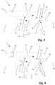
- Fig. 3 the next step of the process according to the invention is shown.
- the first edge 21 of the dough piece 20 is turned over until it is detected by the lower belt section 11 of the second winding belt 10.
- the conveying direction 9 opposite direction of movement of the lower belt section 11 the first edge 21 of the dough piece 20 is turned backwards down until about a whole winding is reached, as in Fig. 4 is illustrated.
- Fig. 5 The next step of the process according to the invention is in Fig. 5 shown.
- the first end 4 is returned to the home position Fig. 1 moved back and then braked the lower belt section 11 of the second winding belt 10 after a fourth predetermined time back to the second predetermined speed.
- the wrapped dough piece 20 is pulled between the upper belt section 3 and the lower belt section 11 in the winding space 18. Since the upper belt section 3 is driven at a higher speed relative to the lower belt section 11, a movement of the dough piece 20 results in the conveying direction 9, wherein the dough piece 20 is further wound due to the different direction of the upper belt section 3 and the lower belt section 11, as this is symbolized by the curved arrow.
- the Fig. 6 shows a particularly preferred embodiment of the inventive method.
- the first end 4 becomes a sixth one predetermined time by a second predetermined distance to the second winding belt 10 moves towards.
- 22 pressure is applied during the winding of the resulting from the dough piece 20 dough product.
- the second winding band 10 is driven at a fourth predetermined speed higher than the first predetermined speed for an eighth predetermined time.
- the fifth, sixth, seventh and eighth predetermined time are selected so that the movement of the front end 4 and the driving of the second winding tape 10 at the fourth predetermined speed takes place at least partially simultaneously.
- the first end 4 is then moved back to the home position and the second winding tape 10 is driven again at the second predetermined speed.
- the dough product 22 is finished in the winding space 18 and transferred to the discharge belt 17. Meanwhile, another dough piece 20 is conveyed to the first end 4 by the feed belt 16.
Landscapes
- Life Sciences & Earth Sciences (AREA)
- Engineering & Computer Science (AREA)
- Food Science & Technology (AREA)
- Manufacturing And Processing Devices For Dough (AREA)
Description
- Die Erfindung betrifft ein Verfahren zur Herstellung von gewickelten Teigprodukten aus Teigstücken, insbesondere zur Herstellung von Croissants aus Teigstücken.
- Aus dem Stand der Technik sind unterschiedliche Vorrichtungen und Verfahren zum Aufwickeln von Teigstücken bekannt. Insbesondere können gewickelte Teigprodukte, wie beispielsweise Croissants, durch Aufrollen eines flachen Teigstückes zwischen zwei gegenläufigen Bändern hergestellt werden.
- Beispielsweise offenbart die
EP 0 204 490 A1 eine Vorrichtung mit einem Wickelmechanismus, der über zwei übereinander angeordneten Förderbänder verfügt und die eine gegenläufige Bandlaufrichtung aufweisen. Das untere Band hat eine höhere Geschwindigkeit als das obere Band. Zunächst wird ein Teigstück durch einen Walzenspalt zu einem ersten Ende des unteren Förderbandes geführt, wo die Vorderkante des Teigstücks nach oben und dort durch Kontakt mit dem oberen Förderband weiter nach hinten umgeschlagen wird. Durch eine Bewegung des vorderen Endes nach unten und damit mit einer Vergrösserung des Abstandes zwischen den beiden Förderbändern im Bereich des ersten Endes wird das teilgewickelte Teigstück zwischen beide Förderbänder gezogen, wobei das Teigstück zwischen den Förderbändern gleichzeitig gefördert und fertiggewickelt wird. Die Vorrichtung kann eine Kontrolleinheit aufweisen, welche die Bewegung des ersten Endes nach einer vorbestimmten Zeit, nachdem ein Teigstück mit diesem in Kontakt kommt, auslöst. Die Geschwindigkeit der Förderbänder kann frei eingestellt werden. - Die
EP 2 762 005 A1 beschreibt eine Fertigungsstrasse für gerollte Teigprodukte, insbesondere für Croissants. Die Fertigungsstrasse umfasst ein Fördermittel für ein Teigprodukt sowie eine Wickelvorrichtung mit einem Umlenkelement, welches von einer Eingriffsposition, in welcher das Umlenkelement über dem Fördermittel hervorsteht, in eine Loslöseposition bewegbar ist. Über dem Umlenkelement ist ein Wickelelement angeordnet, welches mit dem Umlenkelement zusammenwirkt, um das Teigprodukt zu wickeln. Das Umlenkelement wird über eine Antriebsvorrichtung periodisch von der Eingriffsposition in die Loslöseposition bewegt. Sowohl der Oszillationswinkel als auch die Position des Wickelelements lassen sich über entsprechende Einstellmittel verändern. Diese Offenlegung offenbart alle die Merkmale im Oberbegriff des Anspruchs 1. - Die
EP 0 327 856 A1 bezieht sich auf eine Wickelvorrichtung zum Aufwickeln von Croissants. Die Wickelvorrichtung verfügt über zwei übereinander angeordnete Förderbänder, wobei bei einem unteren Förderband die vordere Kante in einer oszillierenden Bewegung auf- und ab bewegt wird. Die Oszillationsbewegungen werden mit den restlichen Bewegungen der Vorrichtung koordiniert. Zwischen einer Walze, des oberen Förderbandes sowie der Vorderkante des unteren Förderbandes bildet sich ein Sitz, in welchem ein Teigstück gerollt werden kann. Ein Teigdreieck wird an der Vorderkante des unteren Förderbandes aufgerollt, wobei durch die nach unten gerichtete Oszillationsbewegung der vorderen Kante das fertig gerollte Teigstück zur Förderung über das untere Transportband freigegeben wird. - Die
GB 491 582 - Aufgabe der Erfindung ist es, eine dem eingangs genannten technischen Gebiet zugehörendes Verfahren zu schaffen, welches gegenüber den im Stand der Technik bekannten Verfahren ein effizienteres Aufwickeln von Teigstücken ermöglicht.
- Die Lösung der Aufgabe ist durch die Merkmale des Anspruchs 1 definiert. Gemäss der vorliegenden Erfindung wird in einem ersten Schritt des Verfahrens mindestens ein Teigstück durch ein Zuführband mit einer ersten vorbestimmten Geschwindigkeit in einer Förderrichtung zu einem ersten Ende eines ersten Wickelbandes hin gefördert. Nach einer ersten vorbestimmten Zeit wird das erste Ende von einer Grundposition um eine erste vorbestimmte Distanz zu einer Einwickelposition angehoben, so dass eine Kante des mindestens einen Teigstückes beim Erreichen des ersten Endes von diesem nach oben umgeschlagen wird. Anschliessend wird die umgeschlagene Kante durch ein zweites Wickelband erfasst, wobei das zweite Wickelband oberhalb des ersten Wickelbandes angeordnet ist, so dass zwischen einer oberen Bandstrecke des ersten Wickelbandes und einer unteren Bandstrecke des zweiten Wickelbandes ein Wickelraum gebildet wird. Die untere Bandstrecke des zweiten Wickelbandes wird entgegen der Förderrichtung mit einer dritten vorbestimmten Geschwindigkeit angetrieben, welche höher ist als die erste vorbestimmte Geschwindigkeit. Nach einer dritten vorbestimmten Zeit wird das erste Ende in die Grundposition bewegt und das zweite Wickelband wird nach einer vierten vorbestimmten Zeit mit einer zweiten Geschwindigkeit, welche tiefer ist als die erste vorbestimmte Geschwindigkeit und die dritte vorbestimmte Geschwindigkeit, angetrieben, so dass das eingeschlagene Teigprodukt in den Wickelraum zu einem zweiten Ende des ersten Wickelbandes hin gefördert und dabei gewickelt wird.
- Durch die Erhöhung der Geschwindigkeit des zweiten Wickelbandes beim Einwickeln kann eine besonders enge erste Wicklung erzielt werden.
- Die Teigstücke sind vorzugsweise vorgängig kalibrierte sowie ausgestanzte Teigstücke, welche eine bestimmte Form aufweisen. Sollen beispielsweise Croissants hergestellt werden, so weisen die Teigstücke vorzugsweise die Form eines Trapezes auf. Grundsätzlich können unterschiedlich geformte Teigstücke mit der erfindungsgemässen Vorrichtung sowie dem erfindungsgemässen Verfahren zu gewickelten Teigprodukten verarbeitet werden, wie beispielsweise viereckige, dreieckige, trapezförmige, runde oder beliebig polygonale Teigstücke. Die Teigprodukte können dabei sowohl ungefüllt oder mit einer Füllung versehen sein, wie beispielsweise einer Nuss-, Mandel- oder Schokoladenfüllung. Bei der Herstellung von gefüllten Teigprodukten wird das Füllmaterial vorgängig auf die Teigstücke aufgetragen, beispielsweise mittels einer Gussvorrichtung.
- Vorzugsweise wird gleichzeitig nur eine Linie des Teigstückes mittels des erfindungsgemässen Verfahrens oder der Vorrichtung gewickelt. In der vorliegenden Anmeldung wird unter "Linie" die Anordnung von Teigstücken beziehungsweise von Teigprodukten verstanden, welche in rechtwinkliger Richtung relativ zur Förderrichtung nebeneinander liegen. In jeder Linie sind vorzugsweise mehrere Teigstücke beziehungsweise Teigprodukte nebeneinander angeordnet. Die nebeneinander angeordneten Teigstücke beziehungsweise Teigprodukte mehrerer Linien bilden in Förderrichtung Reihen an Teigstücken beziehungsweise an Teigprodukten. Vorzugsweise werden mit der erfindungsgemässen Vorrichtung eine bis zehn Reihen an Teigstücken pro Linie gleichzeitig gewickelt.
- Das erste Wickelband wird durch einen ersten Antrieb derart angetrieben, dass sich dessen obere Bandstrecke mit der ersten vorbestimmten Geschwindigkeit in die Förderrichtung bewegt. Vorzugsweise wird die obere Bandstrecke des ersten Wickelbandes während des gesamten Verfahrens konstant mit der ersten vorbestimmten Geschwindigkeit in Förderrichtung durch den ersten Antrieb angetrieben.
- Vorzugsweise wird nach einer fünften vorbestimmten Zeit das erste Ende während einer sechsten vorbestimmten Zeit um eine zweite vorbestimmte Distanz angehoben. Die sechste vorbestimmte Zeit ist dabei kürzer als diejenige Zeit, welche nötig ist, um das Teigprodukt durch den Wickelraum zu fördern.
- Durch das erneute Anheben des ersten Endes während des Fertigwickelns des Teigprodukts kann ein vorbestimmter Druck auf dasselbe ausgeübt werden, um Form und Wicklung des Teigprodukts zu beeinflussen.
- Vorzugsweise entspricht die zweite vorbestimmte Distanz einem vorbestimmten prozentualen Wert der ersten vorbestimmten Distanz.
- Vorzugsweise wird nach einer siebten vorbestimmten Zeit das zweite Wickelband während einer achten vorbestimmten Zeit auf eine vierte vorbestimmte Geschwindigkeit, welche höher ist als die zweite vorbestimmte Geschwindigkeit, angetrieben. Die siebte vorbestimmte Zeit ist dabei kleiner als die zum Fördern des Teigprodukts durch den Wickelraum nötige Zeit.
- Durch die Erhöhung der Geschwindigkeit des zweiten Wickelbandes während sich das Teigprodukt im Wickelraum befindet, kann die Form und Wicklung der Teigprodukte weiter beeinflusst werden. Insbesondere erhöht sich dadurch die Verweilzeit der Teigprodukte im Wickelraum, da sich die Fördergeschwindigkeit derselben im Wickelraum verlangsamt oder umgekehrt. Dies ist auf den Geschwindigkeitsunterschied zwischen dem ersten Wickelband und dem zweiten Wickelband zurückzuführen. Ist die vierte vorbestimmte Geschwindigkeit gleich hoch wie die erste vorbestimmte Geschwindigkeit resultiert kein Geschwindigkeitsunterschied und das Teigprodukt wird im Wickelraum im Wesentlichen am gleichen Ort fertiggewickelt. Ist die vierte vorbestimmte Geschwindigkeit höher als die erste vorbestimmte Geschwindigkeit, so wird das Teigprodukt während der achten vorbestimmten Zeit entgegen der Förderrichtung zum ersten Ende des ersten Wickelbandes hin gefördert.
- Bevorzugt sind die fünfte, sechste, siebte und achte vorbestimmte Zeit derart gewählt, dass das Anheben des ersten Endes sowie die Beschleunigung des zweiten Wickelbandes zumindest teilweise gleichzeitig stattfinden. Dadurch können bei den Teigprodukten zusätzliche Wicklungen erzeugt werden.
- Insbesondere bevorzugt sind dabei die fünfte vorbestimmte Zeit und die siebte vorbestimmte Zeit und/oder die sechste vorbestimmte Zeit sowie die achte vorbestimmte Zeit gleich. Das heisst, dass die Beschleunigung des zweiten Wickelbandes sowie das Anheben des ersten Endes um die zweite vorbestimmte Distanz gleichzeitig stattfinden. Ferner kann das Antreiben des zweiten Wickelbandes mit der vierten vorbestimmten Geschwindigkeit gleich lange dauern wie das Anheben des ersten Endes um die zweite vorbestimmte Distanz. Insbesondere bevorzugt finden die beiden Ereignisse gleichzeitig statt und dauern gleich lange an, d.h. die fünfte vorbestimmte Zeit ist gleich wie die siebte vorbestimmte Zeit und die sechste vorbestimmte Zeit ist gleich wie die achte vorbestimmte Zeit.
- Dadurch wird es möglich, bei nur gering höherer Verweilzeit des Teigprodukts im Wickelraum zusätzliche Wicklungen zu erzeugen.
- Die vorliegende Anmeldung betrifft weiter die Verwendung des oben beschriebenen Verfahrens zur Herstellung von Croissants, insbesondere von gefüllten Croissants, oder von Baguettes aus Teigstücken.
- Aus der nachfolgenden Detailbeschreibung und der Gesamtheit der Patentansprüche ergeben sich weitere vorteilhafte Ausführungsformen und Merkmalskombinationen der Erfindung.
- Die zur Erläuterung des Ausführungsbeispiels verwendeten Zeichnungen zeigen:
- Fig. 1
- den ersten Schritt des erfindungsgemässen Verfahrens anhand einer schematische Seitenansicht einer Vorrichtung, welche zur Durchführung des erfindungsgemässen Verfahrens geeignet ist;
- Figs. 2, 3
- den zweiten Schritt des erfindungsgemässen Verfahrens
- Fig. 4
- der dritte Schritt des erfindungsgemässen Verfahrens;
- Fig. 5
- der vierte Schritt des erfindungsgemässen Verfahrens, bei dem das erste Ende auf die Grundposition zurückbewegt wird;
- Fig. 6
- eine bevorzugte Ausführungsform, bei welcher das erste Ende um eine zweite vorbestimmte Distanz zum zweiten Wickelband hin bewegt und dieses mit einer vierten vorbestimmten Geschwindigkeit angetrieben wird;
- Fig. 7
- ein Endschritt des erfindungsgemässen Verfahrens, bei welchem das fertig gewickelte Teigprodukt auf ein Abführband transferiert wird, wobei gleichzeitig ein nächstes Teigstück zum ersten Ende hin gefördert wird.
- Grundsätzlich sind in den Figuren gleiche Teile mit gleichen Bezugszeichen versehen.
- Die
Fig. 1 zeigt einen ersten Schritt des erfindungsgemässen Verfahrens anhand einer schematische Seitenansicht einer Vorrichtung 1, welche zur Durchführung des erfindungsgemässen Verfahrens geeignet ist. Die Vorrichtung 1 ist zwischen einem Zuführband 16 und einem Abführband 17, welche beide nur teilweise dargestellt sind, angeordnet. Die Vorrichtung 1 verfügt über ein erstes Wickelband 2. Das erste Wickelband 2 läuft über drei Umlenkrollen 6, 7.1, 7.2, wobei zwei erste Umlenkrollen 7.1, 7.2 im Wesentlichen vertikal übereinander angeordnet sind. Die beiden ersten Umlenkrollen sind dabei an einem ersten Ende 4 des ersten Wickelbandes 2 angeordnet. Zwischen den beiden zweiten Umlenkrollen 7.1, 7.2 bildet das zweite Wickelband einen im Wesentlichen ebenen Endbandbereich. Die eine zweite Umlenkrolle 6 wirkt mit einem ersten Antrieb 5 zusammen. Über diesen ersten Antrieb 5 lässt sich das erste Wickelband 2 derart antreiben, dass eine obere Bandstrecke 3 mit einer ersten vorbestimmten Geschwindigkeit in einer Förderrichtung eines Teigstücks 20 bewegt wird. Die erste vorbestimmte Geschwindigkeit sowie die Förderrichtung sind durch einen ersten Pfeil 9 angedeutet. Ein dritter Antrieb 8 wirkt mit dem ersten Ende 4 des ersten Wickelbandes 2 derart zusammen, dass dieser im Wesentlichen in vertikaler Richtung bewegt werden kann. In der Darstellung derFig. 1 befindet sich das erste Ende 4 in einer Grundposition. In dieser Grundposition befindet sich die obere Bandstrecke 3 am ersten Ende 4 im Wesentlichen auf gleicher Höhe mit dem Zuführband 16. - Oberhalb des ersten Wickelbandes 2 ist ein zweites Wickelband 10 angeordnet. Das zweite Wickelband 10 wird über eine dritte Umlenkrolle 13 sowie über eine vierte Umlenkrolle 14 geführt. Über einen zweiten Antrieb 12, welcher in der gezeigten Ausführungsform auf die dritte Umlenkrolle 13 einwirkt, kann das zweite Wickelband 10 derart angetrieben werden, dass eine untere Bandstrecke 11, welche der oberen Bandstrecke 3 des ersten Wickelbandes 2 gegenüberliegt, entgegen der Förderrichtung 9 mit einer zweiten vorbestimmten Geschwindigkeit, welche kleiner ist als die erste vorbestimmte Geschwindigkeit, angetrieben werden kann. Die Laufrichtung sowie die zweite vorbestimmte Geschwindigkeit der unteren Bandstrecke 11 sind mit einem zweiten Pfeil 15 angedeutet.
- Zwischen der oberen Bandstrecke 3 des ersten Wickelbandes 2 sowie der unteren Bandstrecke 11 des oberen Wickelbandes 10 wird ein Wickelbereich 18 der Vorrichtung 1 gebildet.
- Die Vorrichtung 1 verfügt im Weiteren über eine Steuerungseinheit 19, welche mit dem ersten Antrieb 5, dem zweiten Antrieb 12 sowie dem dritten Antrieb 8 verbunden ist, um diese zu steuern. Die Steuerungseinheit verfügt über Mittel, mit denen sich die vorbestimmten Parameter der Vorrichtung 1, wie zum Beispiel die erste vorbestimmte Geschwindigkeit und die zweite vorbestimmte Geschwindigkeit, durch einen Benutzer einstellen beziehungsweise verändern lassen.
- Das Teigstück 20 wird hierbei zum ersten Ende 4 des ersten Wickelbandes 2 hin gefördert.
- Die
Fig. 2 stellt im Wesentlichen den zweiten Schritt des erfindungsgemässen Verfahrens dar. Das erste Ende 4 ist um eine erste vorbestimmte Distanz zum zweiten Wickelband 10 hin in eine Aufwickelposition bewegt. Die Bewegung des ersten Endes 4 erfolgt über den dritten Antrieb 8, welcher beispielhaft als Kolben angedeutet ist. In der Aufwickelposition steht die obere Bandstrecke 3 über der Ebene des Zuführbandes 16, so dass ein zum ersten Ende 4 hin gefördertes Teigstück 20 mit einer ersten Kante 21 auf den Endbandbereich stösst. Durch die fortgesetzte Förderung des Teigstückes 20 durch das Zuführband 16 sowie durch die im Wesentlichen vertikal nach oben gerichtete Laufrichtung des ersten Wickelbandes 2 am ersten Ende 4 wird die erste Kante 21 des Teigstücks 20 nach oben umgeschlagen. - Der zweite Antrieb 12 beschleunigt das zweite Wickelband 10 derart, dass die untere Bandstrecke 11 mit einer dritten Geschwindigkeit, welche höher ist als die erste Geschwindigkeit, entgegen der Förderrichtung 9 angetrieben wird. Die höhere Laufgeschwindigkeit der unteren Bandstrecke 11 ist durch den verlängerten zweiten Pfeil 15 symbolisch dargestellt.
- In der
Fig. 3 ist der nächste Schritt des erfindungsgemässen Verfahrens dargestellt. Die erste Kante 21 des Teigstücks 20 wird soweit umgeschlagen, bis diese durch die untere Bandstrecke 11 des zweiten Wickelbandes 10 erfasst wird. Durch die der Förderrichtung 9 entgegengesetzte Laufrichtung der unteren Bandstrecke 11 wird die erste Kante 21 des Teigstücks 20 nach hinten unten umgeschlagen, bis ca. eine ganze Wicklung erreicht ist, wie dies inFig. 4 veranschaulicht wird. - Der nächste Schritt des erfindungsgemässen Verfahrens ist in
Fig. 5 gezeigt. Nach einer dritten vorbestimmten Zeit wird das erste Ende 4 wieder in die Grundposition gemässFig. 1 zurückbewegt und die untere Bandstrecke 11 des zweiten Wickelbands 10 anschliessend nach einer vierten vorbestimmten Zeit wieder auf die zweite vorbestimmte Geschwindigkeit abgebremst. Dabei wird das eingewickelte Teigstück 20 zwischen der oberen Bandstrecke 3 und der unteren Bandstrecke 11 in den Wickelraum 18 gezogen. Da die obere Bandstrecke 3 relativ zur unteren Bandstrecke 11 mit einer höheren Laufgeschwindigkeit angetrieben wird, resultiert eine Bewegung des Teigstücks 20 in die Förderrichtung 9, wobei das Teigstück 20 aufgrund der unterschiedlichen Laufrichtung der oberen Bandstrecke 3 und der unteren Bandstrecke 11 weiterhin gewickelt wird, wie dies durch den gebogenen Pfeil symbolisiert ist. - Die
Fig. 6 zeigt eine besonders bevorzugte Ausführungsform des erfindungsgemässen Verfahrens. Nach einer fünften vorbestimmten Zeit wird das erste Ende 4 für eine sechste vorbestimmte Zeit um eine zweite vorbestimmte Distanz zum zweiten Wickelband 10 hin bewegt. Dadurch wird während des Wickelns des aus dem Teigstück 20 entstehenden Teigprodukts 22 Druck ausgeübt. Nach einer siebten vorbestimmten Zeit wird zudem während einer achten vorbestimmten Zeit das zweite Wickelband 10 mit einer vierten vorbestimmten Geschwindigkeit, welche höher als die erste vorbestimmte Geschwindigkeit ist, angetrieben. Vorzugsweise sind die fünfte, sechste, siebte und achte vorbestimmte Zeit derart gewählt, dass das Bewegen des vorderen Endes 4 sowie das Antreiben des zweiten Wickelbandes 10 mit der vierten vorbestimmten Geschwindigkeit zumindest teilweise gleichzeitig stattfindet. - Wie in
Fig. 7 dargestellt, wird anschliessend das erste Ende 4 wieder in die Grundposition bewegt und das zweite Wickelband 10 wird wieder mit der zweiten vorbestimmten Geschwindigkeit angetrieben. Dabei wird das Teigprodukt 22 im Wickelraum 18 fertiggewickelt und auf das Abführband 17 transferiert. Derweil wird durch das Zuführband 16 ein weiteres Teigstück 20 zum ersten Ende 4 hin gefördert.
Claims (6)
- Verfahren zum Wickeln von Teigprodukten (22) aus Teigstücken (20), umfassend die Schritte:a) Fördern mindestens eines Teigstückes (20) durch ein Zuführband (16) mit einer ersten Geschwindigkeit in einer Förderrichtung zu einem ersten Ende (4) eines ersten Wickelbandes (2) hin, wobei ein erster Antrieb eine obere Bandstrecke des ersten Wickelbandes mit der ersten vorbestimmten Geschwindigkeit in Förderrichtung antreibt;b) nach einer ersten vorbestimmten Zeit anheben des ersten Endes (4) von einer Grundposition um eine erste vorbestimmte Distanz zu einer Einwickelposition, so dass eine erste Kante (21) des mindestens einen Teigstückes (20) beim Erreichen des ersten Endes (4) von diesem nach oben umgeschlagen wird;c) erfassen der umgeschlagenen ersten Kante (21) durch eine untere Bandstrecke (11) eines zweiten Wickelbandes (10), welches oberhalb des ersten Wickelbandes (2) angeordnet ist, so dass zwischen einer oberen Bandstrecke (3) des ersten Wickelbandes (2) und der unteren Bandstrecke (11) des zweiten Wickelbandes (10) ein Wickelraum (18) gebildet wird, wobei das zweite Wickelband (10) durch einen zweiten Antrieb (12) derart angetrieben wird, dass die untere Bandstrecke (11) mit einer zweiten Geschwindigkeit, welche geringer ist als die erste Geschwindigkeit, entgegen der Förderrichtung bewegt wird;dadurch gekennzeichnet, dass das Verfahren die folgenden Schritte umfasst:d) nach einer zweiten vorbestimmten Zeit antreiben der unteren Bandstrecke des zweiten Wickelbandes mit einer dritten vorbestimmten Geschwindigkeit, welche höher ist als die erste vorbestimmte Geschwindigkeit und die zweite vorbestimmte Geschwindigkeit, entgegen der Förderrichtung;e) nach einer dritten vorbestimmten Zeit bewegen des ersten Endes (4) in die Grundposition und nach einer vierten vorbestimmten Zeit antreiben der unteren Bandstrecke (11) des zweiten Wickelbandes (10) mit der zweiten vorbestimmten Geschwindigkeit, welche tiefer ist als die erste vorbestimmte Geschwindigkeit, entgegen der Förderrichtung, so dass das eingeschlagene Teigstück (20) in den Wickelraum (18) und zu einem zweiten Ende des ersten Wickelbandes (2) hin gefördert und dabei zu einem Teigprodukt (22) gewickelt wird.
- Verfahren gemäss Anspruch 1, dadurch gekennzeichnet, dass nach einer fünften vorbestimmten Zeit, welche kleiner ist als die zum Fördern des Teigprodukts (22) durch den Wickelraum (18) nötige Zeit, das erste Ende (4) während einer sechsten vorbestimmten Zeit um eine zweite vorbestimmte Distanz angehoben wird.
- Verfahren gemäss einem der Ansprüche 1 oder 2, dadurch gekennzeichnet, dass nach einer siebten vorbestimmten Zeit, welche kleiner ist als die zum Fördern des Teigprodukts (22) durch den Wickelraum (18) nötige Zeit, die untere Bandstrecke (11) des zweiten Wickelbandes (10) während einer achten vorbestimmten Zeit mit einer vierten Geschwindigkeit, welche höher ist als die zweite vorbestimmte Geschwindigkeit, entgegen der Förderrichtung angetrieben wird.
- Verfahren gemäss den Ansprüchen 2 und 3, dadurch gekennzeichnet, dass die fünfte vorbestimmte Zeit sowie die siebte vorbestimmte Zeit und/oder die sechste vorbestimmte Zeit sowie die achte vorbestimmte Zeit gleich sind.
- Verfahren gemäss Anspruch 1, dadurch gekennzeichnet, dass die zweite vorbestimmte Distanz einem vorbestimmten prozentualen Wert der ersten vorbestimmten Distanz entspricht.
- Verwendung eines Verfahrens gemäss einem der Ansprüche 1 bis 5 zum Herstellen von Croissants, insbesondere von gefüllten Croissants, aus Teigstücken.
Applications Claiming Priority (1)
| Application Number | Priority Date | Filing Date | Title |
|---|---|---|---|
| DE102015106138.4A DE102015106138B4 (de) | 2015-04-22 | 2015-04-22 | Vorrichtung und Verfahren zur Herstellung von gewickelten Teigprodukten aus Teigstücken |
Publications (2)
| Publication Number | Publication Date |
|---|---|
| EP3085235A1 EP3085235A1 (de) | 2016-10-26 |
| EP3085235B1 true EP3085235B1 (de) | 2019-05-01 |
Family
ID=55752160
Family Applications (1)
| Application Number | Title | Priority Date | Filing Date |
|---|---|---|---|
| EP16163564.4A Active EP3085235B1 (de) | 2015-04-22 | 2016-04-01 | Verfahren zur herstellung von gewickelten teigprodukten aus teigstücken |
Country Status (2)
| Country | Link |
|---|---|
| EP (1) | EP3085235B1 (de) |
| DE (1) | DE102015106138B4 (de) |
Cited By (1)
| Publication number | Priority date | Publication date | Assignee | Title |
|---|---|---|---|---|
| US11445730B2 (en) * | 2018-11-07 | 2022-09-20 | Pacproinc, Llc | Product rolling arrangement |
Families Citing this family (1)
| Publication number | Priority date | Publication date | Assignee | Title |
|---|---|---|---|---|
| JP7090700B2 (ja) * | 2018-05-31 | 2022-06-24 | レオン自動機株式会社 | 食品生地片の巻き成形装置及びその方法 |
Family Cites Families (6)
| Publication number | Priority date | Publication date | Assignee | Title |
|---|---|---|---|---|
| DE551009C (de) * | 1930-01-30 | 1932-05-24 | Wilhelm Quadt | Teigwickelmaschine |
| GB491582A (en) * | 1936-11-21 | 1938-09-05 | Handelm Nv | Improvements in or relating to the preparation of rolls of dough |
| JPS61271939A (ja) | 1985-05-27 | 1986-12-02 | レオン自動機株式会社 | クロワツサンの製造方法及び装置 |
| IT1220639B (it) | 1988-02-10 | 1990-06-15 | C I M Srl | Macchina avvolgitrice particolarmente per produrre croissants |
| AU605696B2 (en) * | 1988-09-15 | 1991-01-17 | Rheon Automatic Machinery Co. Ltd. | An apparatus and method for producing a dough roll by rolling up a dough piece |
| ITVR20130030A1 (it) | 2013-02-05 | 2014-08-06 | Rondo Schio S R L | Linea di trattamento di prodotti alimentari arrotolati |
-
2015
- 2015-04-22 DE DE102015106138.4A patent/DE102015106138B4/de not_active Expired - Fee Related
-
2016
- 2016-04-01 EP EP16163564.4A patent/EP3085235B1/de active Active
Non-Patent Citations (1)
| Title |
|---|
| None * |
Cited By (1)
| Publication number | Priority date | Publication date | Assignee | Title |
|---|---|---|---|---|
| US11445730B2 (en) * | 2018-11-07 | 2022-09-20 | Pacproinc, Llc | Product rolling arrangement |
Also Published As
| Publication number | Publication date |
|---|---|
| DE102015106138A1 (de) | 2016-10-27 |
| EP3085235A1 (de) | 2016-10-26 |
| DE102015106138B4 (de) | 2018-05-09 |
Similar Documents
| Publication | Publication Date | Title |
|---|---|---|
| DE69421528T2 (de) | Umwickler mit Kontaktantrieb und Verfahren zur Minimalisierung des Schlupfes zwischen Antriebsrolle und Bahn | |
| DD248280A5 (de) | Apparat und verfahren zur herstellung von hoernchen | |
| DE102011011049B4 (de) | Verfahren und Vorrichtung zum Ausrichten von gewickelten Teigprodukten in einer definierten Schlusslage | |
| EP3642144B1 (de) | Vorrichtung zur bereitstellung eines spulenförmigen polsterungsprodukts für verpackungszwecke | |
| WO2009108970A1 (de) | Möbelantrieb mit einer antriebseinheit | |
| EP1595438B1 (de) | Maschine zum Aufnehmen und Pressen von landwirtschaftlichem Erntegut | |
| DE102008000763A1 (de) | Teig-Querstrecksystem | |
| DE102015106138B4 (de) | Vorrichtung und Verfahren zur Herstellung von gewickelten Teigprodukten aus Teigstücken | |
| EP3544438B1 (de) | Verfahren und vorrichtung zur herstellung eines wickels aus einem teigstück und einem trennblatt | |
| EP2647289A1 (de) | System zum Überlappen, Falten und/oder Schichten eines Teigbandes | |
| WO2012041740A1 (de) | Verfahren und einrichtung zum herstellen eines führungssegmentes für pendelrollenlager oder dergleichen | |
| DE2754147C2 (de) | ||
| DE3505597A1 (de) | Vorrichtung zum bilden von mit abstand aufeinanderfolgenden reihen | |
| DE3326754A1 (de) | Verfahren und vorrichtung zur herstellung von filtern | |
| EP1111997B1 (de) | Verfahren, komponente und deren anordnung für die teigverarbeitung | |
| AT326065B (de) | Vorrichtung zum u- bzw. sichelförmigem biegen von langgewirkten backwarenrohlingen, insbesondere kipferlrohlingen | |
| DE3237844A1 (de) | Verfahren und einrichtung zum aufrollen flacher teigstuecke | |
| CH690715A5 (de) | Fördereinrichtung für Druckereierzeugnisse. | |
| WO2017059999A1 (de) | Faltriemen für eine vorrichtung zum falten von faltschachtelzuschnitten | |
| DE3442943A1 (de) | Vorrichtung zum falten der oeffnung von gefuellten saecken | |
| DE102012218683A1 (de) | Vorrichtung zur Herstellung eines Polsterungsprodukts aus Papier | |
| EP1366667B1 (de) | Vorrichtung und Verfahren zum Herstellen von gewickelten Teigprodukten | |
| DE68905996T2 (de) | Hochgeschwindigkeitsfaltmaschine fuer elastisches bandmaterial. | |
| DE1961407B1 (de) | Verfahren zum Zufuehren von Tabak unter gleichzeitiger Verdichtung zu einer Verarbeitungsvorrichtung sowie Vorrichtung zum Durchfuehren des Verfahrens zum Abteilen von Portionen gleichen Gewichts von einem Tabakstrang | |
| EP0080519A1 (de) | Verfahren zum Falten von Plakaten und Faltmaschine zu dessen Durchführung |
Legal Events
| Date | Code | Title | Description |
|---|---|---|---|
| PUAI | Public reference made under article 153(3) epc to a published international application that has entered the european phase |
Free format text: ORIGINAL CODE: 0009012 |
|
| AK | Designated contracting states |
Kind code of ref document: A1 Designated state(s): AL AT BE BG CH CY CZ DE DK EE ES FI FR GB GR HR HU IE IS IT LI LT LU LV MC MK MT NL NO PL PT RO RS SE SI SK SM TR |
|
| AX | Request for extension of the european patent |
Extension state: BA ME |
|
| STAA | Information on the status of an ep patent application or granted ep patent |
Free format text: STATUS: REQUEST FOR EXAMINATION WAS MADE |
|
| 17P | Request for examination filed |
Effective date: 20170126 |
|
| RBV | Designated contracting states (corrected) |
Designated state(s): AL AT BE BG CH CY CZ DE DK EE ES FI FR GB GR HR HU IE IS IT LI LT LU LV MC MK MT NL NO PL PT RO RS SE SI SK SM TR |
|
| STAA | Information on the status of an ep patent application or granted ep patent |
Free format text: STATUS: EXAMINATION IS IN PROGRESS |
|
| 17Q | First examination report despatched |
Effective date: 20171024 |
|
| GRAP | Despatch of communication of intention to grant a patent |
Free format text: ORIGINAL CODE: EPIDOSNIGR1 |
|
| STAA | Information on the status of an ep patent application or granted ep patent |
Free format text: STATUS: GRANT OF PATENT IS INTENDED |
|
| INTG | Intention to grant announced |
Effective date: 20181010 |
|
| GRAJ | Information related to disapproval of communication of intention to grant by the applicant or resumption of examination proceedings by the epo deleted |
Free format text: ORIGINAL CODE: EPIDOSDIGR1 |
|
| STAA | Information on the status of an ep patent application or granted ep patent |
Free format text: STATUS: EXAMINATION IS IN PROGRESS |
|
| GRAP | Despatch of communication of intention to grant a patent |
Free format text: ORIGINAL CODE: EPIDOSNIGR1 |
|
| STAA | Information on the status of an ep patent application or granted ep patent |
Free format text: STATUS: GRANT OF PATENT IS INTENDED |
|
| INTG | Intention to grant announced |
Effective date: 20181123 |
|
| GRAS | Grant fee paid |
Free format text: ORIGINAL CODE: EPIDOSNIGR3 |
|
| GRAA | (expected) grant |
Free format text: ORIGINAL CODE: 0009210 |
|
| STAA | Information on the status of an ep patent application or granted ep patent |
Free format text: STATUS: THE PATENT HAS BEEN GRANTED |
|
| AK | Designated contracting states |
Kind code of ref document: B1 Designated state(s): AL AT BE BG CH CY CZ DE DK EE ES FI FR GB GR HR HU IE IS IT LI LT LU LV MC MK MT NL NO PL PT RO RS SE SI SK SM TR |
|
| REG | Reference to a national code |
Ref country code: GB Ref legal event code: FG4D Free format text: NOT ENGLISH |
|
| REG | Reference to a national code |
Ref country code: CH Ref legal event code: EP Ref country code: AT Ref legal event code: REF Ref document number: 1125697 Country of ref document: AT Kind code of ref document: T Effective date: 20190515 |
|
| REG | Reference to a national code |
Ref country code: DE Ref legal event code: R096 Ref document number: 502016004382 Country of ref document: DE |
|
| REG | Reference to a national code |
Ref country code: IE Ref legal event code: FG4D Free format text: LANGUAGE OF EP DOCUMENT: GERMAN |
|
| REG | Reference to a national code |
Ref country code: CH Ref legal event code: NV Representative=s name: KELLER AND PARTNER PATENTANWAELTE AG, CH |
|
| REG | Reference to a national code |
Ref country code: NL Ref legal event code: FP |
|
| REG | Reference to a national code |
Ref country code: LT Ref legal event code: MG4D |
|
| PG25 | Lapsed in a contracting state [announced via postgrant information from national office to epo] |
Ref country code: HR Free format text: LAPSE BECAUSE OF FAILURE TO SUBMIT A TRANSLATION OF THE DESCRIPTION OR TO PAY THE FEE WITHIN THE PRESCRIBED TIME-LIMIT Effective date: 20190501 Ref country code: LT Free format text: LAPSE BECAUSE OF FAILURE TO SUBMIT A TRANSLATION OF THE DESCRIPTION OR TO PAY THE FEE WITHIN THE PRESCRIBED TIME-LIMIT Effective date: 20190501 Ref country code: SE Free format text: LAPSE BECAUSE OF FAILURE TO SUBMIT A TRANSLATION OF THE DESCRIPTION OR TO PAY THE FEE WITHIN THE PRESCRIBED TIME-LIMIT Effective date: 20190501 Ref country code: PT Free format text: LAPSE BECAUSE OF FAILURE TO SUBMIT A TRANSLATION OF THE DESCRIPTION OR TO PAY THE FEE WITHIN THE PRESCRIBED TIME-LIMIT Effective date: 20190901 Ref country code: NO Free format text: LAPSE BECAUSE OF FAILURE TO SUBMIT A TRANSLATION OF THE DESCRIPTION OR TO PAY THE FEE WITHIN THE PRESCRIBED TIME-LIMIT Effective date: 20190801 Ref country code: ES Free format text: LAPSE BECAUSE OF FAILURE TO SUBMIT A TRANSLATION OF THE DESCRIPTION OR TO PAY THE FEE WITHIN THE PRESCRIBED TIME-LIMIT Effective date: 20190501 Ref country code: AL Free format text: LAPSE BECAUSE OF FAILURE TO SUBMIT A TRANSLATION OF THE DESCRIPTION OR TO PAY THE FEE WITHIN THE PRESCRIBED TIME-LIMIT Effective date: 20190501 Ref country code: FI Free format text: LAPSE BECAUSE OF FAILURE TO SUBMIT A TRANSLATION OF THE DESCRIPTION OR TO PAY THE FEE WITHIN THE PRESCRIBED TIME-LIMIT Effective date: 20190501 |
|
| PG25 | Lapsed in a contracting state [announced via postgrant information from national office to epo] |
Ref country code: BG Free format text: LAPSE BECAUSE OF FAILURE TO SUBMIT A TRANSLATION OF THE DESCRIPTION OR TO PAY THE FEE WITHIN THE PRESCRIBED TIME-LIMIT Effective date: 20190801 Ref country code: GR Free format text: LAPSE BECAUSE OF FAILURE TO SUBMIT A TRANSLATION OF THE DESCRIPTION OR TO PAY THE FEE WITHIN THE PRESCRIBED TIME-LIMIT Effective date: 20190802 Ref country code: RS Free format text: LAPSE BECAUSE OF FAILURE TO SUBMIT A TRANSLATION OF THE DESCRIPTION OR TO PAY THE FEE WITHIN THE PRESCRIBED TIME-LIMIT Effective date: 20190501 Ref country code: LV Free format text: LAPSE BECAUSE OF FAILURE TO SUBMIT A TRANSLATION OF THE DESCRIPTION OR TO PAY THE FEE WITHIN THE PRESCRIBED TIME-LIMIT Effective date: 20190501 |
|
| PG25 | Lapsed in a contracting state [announced via postgrant information from national office to epo] |
Ref country code: IS Free format text: LAPSE BECAUSE OF FAILURE TO SUBMIT A TRANSLATION OF THE DESCRIPTION OR TO PAY THE FEE WITHIN THE PRESCRIBED TIME-LIMIT Effective date: 20190901 |
|
| PG25 | Lapsed in a contracting state [announced via postgrant information from national office to epo] |
Ref country code: EE Free format text: LAPSE BECAUSE OF FAILURE TO SUBMIT A TRANSLATION OF THE DESCRIPTION OR TO PAY THE FEE WITHIN THE PRESCRIBED TIME-LIMIT Effective date: 20190501 Ref country code: DK Free format text: LAPSE BECAUSE OF FAILURE TO SUBMIT A TRANSLATION OF THE DESCRIPTION OR TO PAY THE FEE WITHIN THE PRESCRIBED TIME-LIMIT Effective date: 20190501 Ref country code: SK Free format text: LAPSE BECAUSE OF FAILURE TO SUBMIT A TRANSLATION OF THE DESCRIPTION OR TO PAY THE FEE WITHIN THE PRESCRIBED TIME-LIMIT Effective date: 20190501 Ref country code: RO Free format text: LAPSE BECAUSE OF FAILURE TO SUBMIT A TRANSLATION OF THE DESCRIPTION OR TO PAY THE FEE WITHIN THE PRESCRIBED TIME-LIMIT Effective date: 20190501 Ref country code: CZ Free format text: LAPSE BECAUSE OF FAILURE TO SUBMIT A TRANSLATION OF THE DESCRIPTION OR TO PAY THE FEE WITHIN THE PRESCRIBED TIME-LIMIT Effective date: 20190501 |
|
| REG | Reference to a national code |
Ref country code: DE Ref legal event code: R097 Ref document number: 502016004382 Country of ref document: DE |
|
| PG25 | Lapsed in a contracting state [announced via postgrant information from national office to epo] |
Ref country code: SM Free format text: LAPSE BECAUSE OF FAILURE TO SUBMIT A TRANSLATION OF THE DESCRIPTION OR TO PAY THE FEE WITHIN THE PRESCRIBED TIME-LIMIT Effective date: 20190501 Ref country code: IT Free format text: LAPSE BECAUSE OF FAILURE TO SUBMIT A TRANSLATION OF THE DESCRIPTION OR TO PAY THE FEE WITHIN THE PRESCRIBED TIME-LIMIT Effective date: 20190501 |
|
| PLBE | No opposition filed within time limit |
Free format text: ORIGINAL CODE: 0009261 |
|
| STAA | Information on the status of an ep patent application or granted ep patent |
Free format text: STATUS: NO OPPOSITION FILED WITHIN TIME LIMIT |
|
| PG25 | Lapsed in a contracting state [announced via postgrant information from national office to epo] |
Ref country code: TR Free format text: LAPSE BECAUSE OF FAILURE TO SUBMIT A TRANSLATION OF THE DESCRIPTION OR TO PAY THE FEE WITHIN THE PRESCRIBED TIME-LIMIT Effective date: 20190501 |
|
| 26N | No opposition filed |
Effective date: 20200204 |
|
| PG25 | Lapsed in a contracting state [announced via postgrant information from national office to epo] |
Ref country code: PL Free format text: LAPSE BECAUSE OF FAILURE TO SUBMIT A TRANSLATION OF THE DESCRIPTION OR TO PAY THE FEE WITHIN THE PRESCRIBED TIME-LIMIT Effective date: 20190501 |
|
| PG25 | Lapsed in a contracting state [announced via postgrant information from national office to epo] |
Ref country code: SI Free format text: LAPSE BECAUSE OF FAILURE TO SUBMIT A TRANSLATION OF THE DESCRIPTION OR TO PAY THE FEE WITHIN THE PRESCRIBED TIME-LIMIT Effective date: 20190501 |
|
| REG | Reference to a national code |
Ref country code: CH Ref legal event code: PFA Owner name: RONDO BURGDORF AG, CH Free format text: FORMER OWNER: RONDO BURGDORF AG, CH |
|
| PG25 | Lapsed in a contracting state [announced via postgrant information from national office to epo] |
Ref country code: MC Free format text: LAPSE BECAUSE OF FAILURE TO SUBMIT A TRANSLATION OF THE DESCRIPTION OR TO PAY THE FEE WITHIN THE PRESCRIBED TIME-LIMIT Effective date: 20190501 |
|
| PG25 | Lapsed in a contracting state [announced via postgrant information from national office to epo] |
Ref country code: LU Free format text: LAPSE BECAUSE OF NON-PAYMENT OF DUE FEES Effective date: 20200401 |
|
| REG | Reference to a national code |
Ref country code: BE Ref legal event code: MM Effective date: 20200430 |
|
| PG25 | Lapsed in a contracting state [announced via postgrant information from national office to epo] |
Ref country code: BE Free format text: LAPSE BECAUSE OF NON-PAYMENT OF DUE FEES Effective date: 20200430 |
|
| PG25 | Lapsed in a contracting state [announced via postgrant information from national office to epo] |
Ref country code: IE Free format text: LAPSE BECAUSE OF NON-PAYMENT OF DUE FEES Effective date: 20200401 |
|
| PG25 | Lapsed in a contracting state [announced via postgrant information from national office to epo] |
Ref country code: MT Free format text: LAPSE BECAUSE OF FAILURE TO SUBMIT A TRANSLATION OF THE DESCRIPTION OR TO PAY THE FEE WITHIN THE PRESCRIBED TIME-LIMIT Effective date: 20190501 Ref country code: CY Free format text: LAPSE BECAUSE OF FAILURE TO SUBMIT A TRANSLATION OF THE DESCRIPTION OR TO PAY THE FEE WITHIN THE PRESCRIBED TIME-LIMIT Effective date: 20190501 |
|
| REG | Reference to a national code |
Ref country code: AT Ref legal event code: MM01 Ref document number: 1125697 Country of ref document: AT Kind code of ref document: T Effective date: 20210401 |
|
| PG25 | Lapsed in a contracting state [announced via postgrant information from national office to epo] |
Ref country code: MK Free format text: LAPSE BECAUSE OF FAILURE TO SUBMIT A TRANSLATION OF THE DESCRIPTION OR TO PAY THE FEE WITHIN THE PRESCRIBED TIME-LIMIT Effective date: 20190501 |
|
| PG25 | Lapsed in a contracting state [announced via postgrant information from national office to epo] |
Ref country code: AT Free format text: LAPSE BECAUSE OF NON-PAYMENT OF DUE FEES Effective date: 20210401 |
|
| PGFP | Annual fee paid to national office [announced via postgrant information from national office to epo] |
Ref country code: NL Payment date: 20250418 Year of fee payment: 10 |
|
| PGFP | Annual fee paid to national office [announced via postgrant information from national office to epo] |
Ref country code: DE Payment date: 20250422 Year of fee payment: 10 |
|
| PGFP | Annual fee paid to national office [announced via postgrant information from national office to epo] |
Ref country code: GB Payment date: 20250423 Year of fee payment: 10 |
|
| PGFP | Annual fee paid to national office [announced via postgrant information from national office to epo] |
Ref country code: FR Payment date: 20250425 Year of fee payment: 10 |
|
| PGFP | Annual fee paid to national office [announced via postgrant information from national office to epo] |
Ref country code: CH Payment date: 20250501 Year of fee payment: 10 |
|
| REG | Reference to a national code |
Ref country code: CH Ref legal event code: U11 Free format text: ST27 STATUS EVENT CODE: U-0-0-U10-U11 (AS PROVIDED BY THE NATIONAL OFFICE) Effective date: 20260501 |