EP3083007B1 - Verfahren und nassabscheider zum entfernen von teilchen aus gasen - Google Patents
Verfahren und nassabscheider zum entfernen von teilchen aus gasen Download PDFInfo
- Publication number
- EP3083007B1 EP3083007B1 EP14833582.1A EP14833582A EP3083007B1 EP 3083007 B1 EP3083007 B1 EP 3083007B1 EP 14833582 A EP14833582 A EP 14833582A EP 3083007 B1 EP3083007 B1 EP 3083007B1
- Authority
- EP
- European Patent Office
- Prior art keywords
- vertical cylindrical
- liquid
- cylindrical vessel
- particles
- swirl generator
- Prior art date
- Legal status (The legal status is an assumption and is not a legal conclusion. Google has not performed a legal analysis and makes no representation as to the accuracy of the status listed.)
- Active
Links
- 239000007789 gas Substances 0.000 title claims description 167
- 238000000034 method Methods 0.000 title claims description 65
- 239000002245 particle Substances 0.000 title claims description 42
- 239000007788 liquid Substances 0.000 claims description 107
- 238000000926 separation method Methods 0.000 claims description 69
- 239000007787 solid Substances 0.000 claims description 36
- 238000007599 discharging Methods 0.000 claims description 22
- 239000012530 fluid Substances 0.000 claims description 20
- 230000001133 acceleration Effects 0.000 claims description 2
- 230000001419 dependent effect Effects 0.000 description 2
- 239000000428 dust Substances 0.000 description 2
- 239000000126 substance Substances 0.000 description 2
- 229910000831 Steel Inorganic materials 0.000 description 1
- 238000005516 engineering process Methods 0.000 description 1
- 238000005201 scrubbing Methods 0.000 description 1
- 239000010959 steel Substances 0.000 description 1
Images


Classifications
-
- B—PERFORMING OPERATIONS; TRANSPORTING
- B01—PHYSICAL OR CHEMICAL PROCESSES OR APPARATUS IN GENERAL
- B01D—SEPARATION
- B01D47/00—Separating dispersed particles from gases, air or vapours by liquid as separating agent
- B01D47/10—Venturi scrubbers
-
- B—PERFORMING OPERATIONS; TRANSPORTING
- B01—PHYSICAL OR CHEMICAL PROCESSES OR APPARATUS IN GENERAL
- B01D—SEPARATION
- B01D45/00—Separating dispersed particles from gases or vapours by gravity, inertia, or centrifugal forces
- B01D45/12—Separating dispersed particles from gases or vapours by gravity, inertia, or centrifugal forces by centrifugal forces
- B01D45/16—Separating dispersed particles from gases or vapours by gravity, inertia, or centrifugal forces by centrifugal forces generated by the winding course of the gas stream, the centrifugal forces being generated solely or partly by mechanical means, e.g. fixed swirl vanes
-
- B—PERFORMING OPERATIONS; TRANSPORTING
- B01—PHYSICAL OR CHEMICAL PROCESSES OR APPARATUS IN GENERAL
- B01D—SEPARATION
- B01D50/00—Combinations of methods or devices for separating particles from gases or vapours
- B01D50/40—Combinations of devices covered by groups B01D45/00 and B01D47/00
-
- B—PERFORMING OPERATIONS; TRANSPORTING
- B01—PHYSICAL OR CHEMICAL PROCESSES OR APPARATUS IN GENERAL
- B01D—SEPARATION
- B01D2247/00—Details relating to the separation of dispersed particles from gases, air or vapours by liquid as separating agent
- B01D2247/08—Means for controlling the separation process
-
- B—PERFORMING OPERATIONS; TRANSPORTING
- B01—PHYSICAL OR CHEMICAL PROCESSES OR APPARATUS IN GENERAL
- B01D—SEPARATION
- B01D2247/00—Details relating to the separation of dispersed particles from gases, air or vapours by liquid as separating agent
- B01D2247/10—Means for removing the washing fluid dispersed in the gas or vapours
- B01D2247/101—Means for removing the washing fluid dispersed in the gas or vapours using a cyclone
-
- B—PERFORMING OPERATIONS; TRANSPORTING
- B01—PHYSICAL OR CHEMICAL PROCESSES OR APPARATUS IN GENERAL
- B01D—SEPARATION
- B01D2247/00—Details relating to the separation of dispersed particles from gases, air or vapours by liquid as separating agent
- B01D2247/10—Means for removing the washing fluid dispersed in the gas or vapours
- B01D2247/108—Means for removing the washing fluid dispersed in the gas or vapours using vortex inducers
-
- B—PERFORMING OPERATIONS; TRANSPORTING
- B01—PHYSICAL OR CHEMICAL PROCESSES OR APPARATUS IN GENERAL
- B01D—SEPARATION
- B01D45/00—Separating dispersed particles from gases or vapours by gravity, inertia, or centrifugal forces
- B01D45/12—Separating dispersed particles from gases or vapours by gravity, inertia, or centrifugal forces by centrifugal forces
Definitions
- the invention relates to a method for removing particles from gases as defined in the preamble of independent claim 1.
- the invention also relates to a wet scrubber for removing particles from gases as defined in the preamble of independent claim 16.
- Scrubbers are used for scrubbing gas of undesired chemicals and/or dust.
- the object of the invention is to provide an effective method for separation of particles from gases and to provide a compact scrubber that provides for effective separation of particles from gases.
- the method for removing particles from gases of the invention is characterized by the definitions of independent claim 1.
- the wet scrubber for removing particles from gases of the invention is correspondingly characterized by the definitions of independent claim 16.
- separation of particles of solid and/or liquid are separated from the gas in two stages; first in the swirl generator and thereafter in the vertical cylindrical separation space of the first vertical cylindrical vessel.
- venturi channel By placing the venturi channel in the vertical cylindrical separation space of the first vertical cylindrical vessel a duct for connecting the venturi channel and the vertical cylindrical separation space of the first vertical cylindrical vessel becomes unnecessary. This also makes the scrubber more compact i.e. small in size. A scrubber small in size need less space such as less floor space.
- the method and wet scrubber makes also possible a self-carrying structure i.e. there is no or less need for external steel structures for carrying the wet scrubber or parts of the wet scrubber.
- the method and the wet scrubber also allows the degree of separation of particles of solid and/or liquid to be adjusted by adjusting the liquid level in the liquid tank that is in fluid connection with the lower end of the first cylindrical vessel.
- a higher liquid level gives increased velocities for the stream exiting the swirl generator and higher separation efficiency due to increased cyclonic action.
- the swirl generator may have partly open bottom and the liquid level may be raised so that the partly open bottom of the swirl generator is covered with liquid, which leads to reduced wear on the bottom area of the swirl generator.
- the invention relates to a method and to a wet scrubber for removing particles from gases.
- the particles can for example be liquid and/or solid particles of undesired chemicals and/or dust particles.
- the method comprises a first gas feeding step for feeding a stream of particles-laden gas 22 into a gas inlet 1 of a wet scrubber.
- the method comprises a liquid feeding step for feeding liquid such as liquid droplets 23 or liquid in liquid form into the stream of particles-laden gas 22 to form a stream of liquid- and particles-laden gas 24.
- the method comprises an acceleration step for feeding the stream of liquid- and particles-laden gas 24 through a vertically oriented venturi channel 2 of the wet scrubber to raise the velocity of the steam of liquid- and particles-laden gas 24 to form an accelerated stream of liquid- and particles-laden gas 25, wherein the vertically oriented venturi channel 2 having a circular cross-section form.
- the method comprises a swirl step for feeding the accelerated stream of liquid- and particles-laden gas 25 into a swirl generator 3 of the wet scrubber for converting the accelerated stream of liquid- and particles-laden gas 25 into cyclonic streams of liquid- and particles-laden gas 26.
- the method comprises a second gas feeding step for feeding cyclonic streams of liquid- and particles-laden gas 26 through a gas opening 4 from the swirl generator 3 into a vertical cylindrical separation space 5 of a first vertical cylindrical vessel 6 of the wet scrubber for separating liquid and solids from the cyclonic stream of liquid- and particles-laden gas 26 in the cylindrical separation space 5 of the first vertical cylindrical vessel 6 of the wet scrubber by means of the cyclonic motion of the cyclonic stream of liquid- and particles-laden gas 26 and for forming a stream of scrubbed gas 28, wherein the first vertical cylindrical vessel 6 having a first upper end 7 and a first lower end 8.
- the method comprises a gas discharging step for discharging the stream of scrubbed gas 28 from the vertical cylindrical separation space 5 of the first vertical cylindrical vessel 6 of the wet scrubber through a gas outlet 9 in fluid connection with the vertical cylindrical separation space 5 of the first vertical cylindrical vessel 6, wherein the gas outlet 9 is arranged at a level above the gas opening 4.
- the method comprises a collecting step for receiving solid particles 29 and liquid 27 from the vertical cylindrical separation space 5 of the first vertical cylindrical vessel 6 in a liquid tank 13 of the wet scrubber, wherein the liquid tank 13 is in fluid connection with the first lower end 8 of the vertical cylindrical separation space 5 of the first vertical cylindrical vessel 6.
- the method comprises a providing step for providing a second vertical cylindrical vessel 10 having a second upper end 11 and a second lower end 12.
- the method comprises a first arranging step for arranging the second upper end 11 of the second vertical cylindrical vessel 10 in fluid connection with the vertically oriented venturi channel 2 for receiving the accelerated stream of liquid- and particles-laden gas 25 from the vertically oriented venturi channel 2 into the second vertical cylindrical vessel 10.
- the method comprises a second arranging step for arranging the second vertical cylindrical vessel 10 and the swirl generator 3 at least partly in the cylindrical separation space 5 of the first vertical cylindrical vessel 6 so that the first vertical cylindrical vessel 6 at least partly coaxially surrounds the second vertical cylindrical vessel 10 and the swirl generator 3.
- the vertically oriented venture channel 2 can additionally be arranged at least partly in the cylindrical separation space 5 of the first vertical cylindrical vessel 6 so that the first vertical cylindrical vessel 6 at least partly coaxially surrounds the vertically oriented venture channel 2.
- the method may comprise using in the swirl step a swirl generator 3 having an at least partly open bottom 21 in fluid connection with the liquid tank 13 for discharging solid particles and liquid separated in the swirl step in the swirl generator 3 from the swirl generator 3 into the liquid tank 13.
- the method may comprise using in the swirl step a swirl generator 3 having a closed bottom.
- the method comprises preferably, but not necessarily, providing in the vertically oriented venturi channel 2 a vertically movable venturi cone 18 that is axially movable in relation to the vertically oriented venturi channel 2 for adjusting the flow through the vertically oriented venturi channel 2, and adjusting the adjusting the flow through the vertically oriented venturi channel 2 by axially moving the vertically movable venturi cone 18 in relation to the vertically oriented venturi channel 2.
- the method comprises preferably, but not necessarily, discharging the stream of scrubbed gas 28 in the gas discharging step from the vertical cylindrical separation space 5 of the first vertical cylindrical vessel 6 through a gas outlet 9 that is formed in the first vertical cylindrical vessel 6.
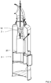
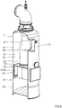
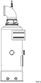
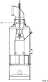
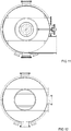
- Figures 1 to 15 shows a wet scrubber and parts of a wet scrubber for performing a first embodiment of the method.
- the swirl generator 3 used in the swirl step may as in the first embodiment shown in figures 1 to 15 , have an upper axial inlet 14 for receiving the stream of accelerated stream of liquid- and particles-laden gas 25, and a blade arrangement 30 forming transversal flow channels 32 for converting the stream of accelerated stream of liquid- and particles-laden gas 25 into tangential streams of liquid- and particles-laden gas.
- the blade arrangement 30 is symmetrical with respect to the vertical cylindrical separation space 5 of the first vertical cylindrical vessel 6 and each transversal flow channel 32 leads from the upper axial inlet 14 and terminates in a gas opening 4 or gas openings 4 in the form of a radial outlet 15.
- This first embodiment of the method includes connecting the upper axial inlet 14 of the swirl generator 3 in fluid connection the second lower end 12 of the second vertical cylindrical vessel 10 for receiving the stream of accelerated stream of liquid- and particles-laden gas 25 from the second vertical cylindrical vessel 10.
- This first embodiment of the method includes arranging the radial outlets 15 of the swirl generator 3 to open up into the vertical cylindrical separation space 5 of the first vertical cylindrical vessel 6.
- the swirl step of this first embodiment of the method includes feeding the stream of accelerated stream of liquid- and particles-laden gas 25 from the second vertical cylindrical vessel 10 through the upper axial inlet 14 of the swirl generator 3 into the swirl generator 3.
- the swirl step of this first embodiment of the method includes converting the stream of accelerated stream of liquid- and particles-laden gas 25 in the flow channels 32 into tangential streams of liquid- and particles-laden gas 37.
- the swirl step of this first embodiment of the method includes discharging tangential streams of liquid- and particles-laden gas 37 from the radial outlets 15 of the swirl generator 3 into the vertical cylindrical separation space 5 of the first vertical cylindrical vessel 6 to form said cyclonic streams liquid- and particles-laden gas 26 in the vertical cylindrical separation space 5 of the first vertical cylindrical vessel 6.
- the swirl generator 3 used in the swirl step in the first embodiment of the method may have a top that except for the upper axial inlet 14 being closed by means least one top cover 20.
- the swirl generator 3 used in the swirl step in the first embodiment of the method may have an at least partly open bottom 21 in fluid connection with the liquid tank 13 for discharging solid particles 29 and liquid 27 separated in the swirl generator 3 from the swirl generator 3 into the liquid tank 13. If the swirl generator 3 used in the swirl step have an at least partly open bottom 21, the method includes discharging solid particles 29 and liquid 27 from the swirl generator 3 from the swirl generator 3 into the liquid tank 13 during the swirl step.
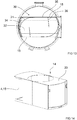
- the swirl generator 3 used in the swirl step in the first embodiment of the method may have a blade arrangement 30 comprising two blades 31 3 leach having a curved section 34, a first plane section 35 having a side that is connected to the curved section 34, and a second plane section 36 having a side that is connected at an angle to the first plane section 35 so that flow channels 32 are formed between said two blades 31, each flow channel 32 leading from the axial inlet 14 of the swirl generator 3 to a radial outlet 15 of the swirl generator 3.
- the method according to the first embodiment comprises preferably, but not necessarily, arranging the swirl generator 3 in the vertical cylindrical separation space 5 of the first vertical cylindrical vessel 6 so that a circumferential space 17 is formed between the swirl generator 3 and the inner wall of the vertical cylindrical separation space 5 of the first vertical cylindrical vessel 6 for improving the gas flow around the swirl generator 3 resulting in a better cyclonic action of the gas.
- the gas flow through the wet scrubber is for example created by means of an external flow generator (not shown in the drawings) in fluid connection with the wet scrubber.
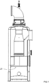
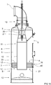
- Figures 16 and 17 shows a scrubber for performing a second embodiment of the method.
- This second embodiment of the method comprises forming an annular space 16 between the first vertical cylindrical vessel 6 and the second vertical cylindrical vessel 10.
- the swirl generator 3 used in the swirl step of the method of this second embodiment has a ring-shaped configuration and comprises a plurality of guide vanes 40 for forming said cyclonic streams of liquid- and solid laden gas 26 of the stream of said accelerated stream of liquid- and solid laden gas 25.
- This second embodiment of the method comprises forming said gas opening 4 for feeding cyclonic streams of liquid- and particles-laden gas 25 from the swirl generator 3 into the vertical cylindrical separation space 5 of the first vertical vessel of an open upper surface 33 of the swirl generator 3.
- This second embodiment of the method comprises arranging the swirl generator 3 in the annular space 16 between the first vertical cylindrical vessel 6 and the second vertical cylindrical vessel 10 for receiving the accelerated stream of liquid- and solid laden gas from the second vertical cylindrical vessel 10.
- This second embodiment of the method comprises preferably, but not necessarily, arranging the swirl generator 3 in the annular space 16 between the first vertical cylindrical vessel 6 and the second vertical cylindrical vessel 10 so that a circumferential space 17 is formed between the swirl generator 3 and the inner wall of the vertical cylindrical separation space 5 of the first vertical cylindrical vessel 6 for allowing solid particles and liquid to flow past the swirl generator 3 from a location above the swirl generator 3 to the liquid tank 13 below the swirl generator 3.
- This second embodiment of the method comprises preferably, but not necessarily, arranging the second vertical cylindrical vessel 10 in the vertical cylindrical separation space 5 of the first vertical cylindrical vessel 6 so that the second lower end 12 of the second vertical cylindrical vessel 10 opening up into the vertical cylindrical separation space 5 of the first vertical cylindrical vessel 6 at a level below the swirl generator 3 and at level above the liquid tank 13.
- This second embodiment of the method comprises preferably, but not necessarily, providing in the providing step a second vertical cylindrical vessel 10 having a second lower end 12 in the form of a circular opening, and arranging the second vertical cylindrical vessel 10 in the second arranging step so that the second lower end 12 of the second vertical cylindrical vessel 10 faces the liquid tank 13.
- the method may include a circulation step for circulating liquid from the liquid tank 13 of the wet scrubber to liquid feeding means 19 to be used in the liquid feeding means.
- the method may include selecting amount of liquid in the liquid tank 13 so that the swirl generator 3 is partly submerged in liquid in the vertical cylindrical separation space 5 of the first vertical cylindrical vessel 6. It is for example possible that the swirl generator 3 is by some centimeters submerged into liquid.
- the method may include adjusting the amount of liquid in the liquid tank 13 so that the position of the liquid level 39 shifts to adjust the velocity of the stream of scrubbed gas 28 that is discharged in the gas discharged step.
- the method may comprise measuring the velocity of the stream of scrubbed gas 28 that is discharged in the gas discharged step and automatically adjusting the amount of liquid in the liquid tank 13 for example to maintain an essentially constant velocity.
- wet scrubber for removing particles such as particles from gases and some embodiments and variants of the wet scrubber will be described in greater detail.
- the wet scrubber comprises a gas inlet 1 for receiving a stream of particles-laden gas 22.
- the particles can be liquid particles and/or solid particles.
- the wet scrubber comprises liquid feeding means 19 for feeding liquid such as liquid droplets 23 or liquid in liquid form into the stream of particles-laden gas to form a stream of liquid- and particles-laden gas 24,
- the wet scrubber comprises a vertically oriented venturi channel 2 for raising the velocity of the steam of liquid- and particles-laden gas 24 to form a stream of accelerated stream of liquid- and particles-laden gas 25.
- the vertically oriented venturi channel 2 has a circular cross-section form.
- the wet scrubber comprises a swirl generator 3 for forming cyclonic streams of liquid- and particles-laden gas 26 of the stream of accelerated stream of liquid- and particles-laden gas 25.
- the wet scrubber comprises a gas opening 4 for feeding the cyclonic streams of liquid- and particles-laden gas 26 from the swirl generator 3.
- the wet scrubber comprises a first vertical cylindrical vessel 6 for receiving the cyclonic streams of liquid- and particles-laden gas 26 from the swirl generator 3 for in the cylindrical separation space 5 of a first vertical cylindrical vessel 6 separate liquid and particles from the cyclonic streams of liquid and particles-laden gas by means of the cyclonic motion of the cyclonic stream of liquid- and particles-laden gas 26 and for forming a stream of scrubbed gas 28, wherein the first vertical cylindrical vessel 6 having an first upper end 7 and a first lower end 8.
- the wet scrubber comprises a gas outlet 9 for removing the stream of scrubbed gas 28 from the cylindrical separation space 5 of the first vertical cylindrical vessel 6.
- the gas outlet 9 is arranged at a level above the gas opening 4.
- the wet scrubber comprises a liquid tank 13 in fluid connection with the first lower end 8 of the first vertical cylindrical vessel 6 for receiving solid particles and liquid from in the cylindrical separation space 5 of the first vertical cylindrical vessel 6.
- the wet scrubber comprises a second vertical cylindrical vessel 10 has an second upper end 11 for receiving the accelerated stream of liquid- and particles-laden gas 25 from the vertically oriented venturi channel 2 and a second lower end 12 for feeding the accelerated stream of liquid- and particles-laden gas 25 from the second vertical cylindrical vessel 10 to the swirl generator 3.
- the second vertical cylindrical vessel 10 and the swirl generator 3 are at least partly arranged in the vertical cylindrical separation space 5 of the first vertical cylindrical vessel 6 so that the first vertical cylindrical vessel 6 coaxially surrounds second vertical cylindrical vessel 10 and the swirl generator 3.
- the vertically oriented venture channel 2 can additionally be arranged at least partly in the cylindrical separation space 5 of the first vertical cylindrical vessel 6 so that the first vertical cylindrical vessel 6 at least partly coaxially surrounds the vertically oriented venture channel 2.
- the swirl generator 3 may be at least partly open towards the liquid tank 13 for discharging solid particles and liquid separated in the swirl generator 3 into the liquid tank 13.
- a venturi cone 18 is preferably, but not necessarily, arranged in the vertically oriented venturi channel 2 so that the venturi cone 18 is axially movable to adjust the flow through the vertically oriented venturi channel 2.
- the gas outlet 9 is preferably, but not necessarily, formed tangentially in the first vertical cylindrical vessel 6
- Figures 1 to 10 show a first embodiment of the wet scrubber.
- the top of the swirl generator 3 has an upper axial inlet 14 connected with and in fluid connection with the second lower end 12 of the second vertical cylindrical vessel 10 for receiving the stream of accelerated stream of liquid- and particles-laden gas 25 from the second vertical cylindrical vessel 10.
- the swirl generator 3 has a blade arrangement 30 for converting the stream of accelerated stream of liquid- and particles-laden gas 25 into tangential streams of liquid- and particles-laden gas 37.
- the blade arrangement 30 of the swirl generator 3 is symmetrical with respect to the vertical cylindrical separation space 5 of the first vertical cylindrical vessel 6.
- the blade arrangement 30 of the swirl generator 3 terminates in gas openings 4 in the form of radial outlets 15 opening up into the vertical cylindrical separation space 5 of the first vertical cylindrical vessel 6 for discharging tangential streams of liquid- and particles-laden gas into the vertical cylindrical separation space 5 of the first vertical cylindrical vessel 6 to form said cyclonic streams liquid- and particles-laden gas in the vertical cylindrical separation space 5 of the first vertical cylindrical vessel 6.
- the top of the swirl generator 3 except for the upper axial inlet 14 is preferably, but not necessarily, closed by means least one top cover 20.
- the swirl generator 3 has preferably, but not necessarily, an at least partly open bottom 21 in fluid connection with the liquid tank 13 for discharging solid particles and liquid separated in the swirl generator 3 from the swirl generator 3 into the liquid tank 13.
- the blade arrangement 30 of the swirl generator 3 comprises preferably, but not necessarily, two blades 31 each having a curved section 34, a first plane section 35 having a side that is connected to the curved section 34, and a second plane section 36 having a side that is connected at an angle to the first plane section 35, and two flow channels 32 are formed between said two blades, each of said two flow channels 32 leading from the axial inlet of the swirl generator 3 to a radial outlet 15 of the swirl generator 3.
- This first embodiment of the scrubber comprises preferably, but not necessarily, a circumferential space 17 between the swirl generator 3 and the inner wall of the vertical cylindrical separation space 5 of the first vertical cylindrical vessel 6 for improving the gas flow around the swirl generator 3 resulting in a better cyclonic action of the gas.
- Figures 16 and 17 show a second embodiment of the wet scrubber
- This second embodiment of the scrubber comprises an annular space 16 between the first vertical cylindrical vessel 6 and the second vertical cylindrical vessel 10.
- the swirl generator 3 is arranged in the annular space 16 between the first vertical cylindrical vessel 6 and the second vertical cylindrical vessel 10 for receiving the accelerated stream of liquid- and solid laden gas from the second vertical cylindrical vessel 10.
- the swirl generator 3 has a ring-shaped configuration and comprises a plurality of guide vanes 40 for forming said cyclonic streams of liquid- and solid laden gas of the stream of said accelerated stream of liquid- and solid laden gas.
- This second embodiment of the scrubber comprises preferably, but not necessarily, a circumferential space 17 between the swirl generator 3 and the inner wall of the vertical cylindrical separation space 5 of the first vertical cylindrical vessel 6 for allowing solid particles and liquid to flow past the swirl generator 3 from a location above the swirl generator 3 to the liquid tank 13 below the swirl generator 3.
- the second lower end 12 of the second vertical cylindrical vessel 10 opens preferably, but not necessarily, up into the vertical cylindrical separation space 5 of the first vertical cylindrical vessel 6 at a level below the swirl generator 3 and at level above the liquid tank 13.
- the second lower end 12 of the second vertical cylindrical vessel 10 being preferably, but not necessarily, in the form of a circular opening facing the liquid tank 13
- the wet scrubber may include a circulation means 38 for circulating liquid from the liquid tank 13 of the wet scrubber to liquid feeding means 19 to be used in the liquid feeding means 19.
Claims (28)
- Verfahren zum Beseitigen von Partikeln, wie von Partikeln aus einem Gas, wobei das Verfahren umfasst:einen ersten Gaseintragsschritt zum Eintragen eines Stromes von partikelbeladenem Gas (22) in einen Gaseinlass (1) eines Nassabscheiders,einen Flüssigkeitseintragsschritt zum Eintragen von Flüssigkeit (23) in den Strom von partikelbeladenem Gas, um einen Strom von flüssigkeits- und partikelbeladenem Gas (24) auszubilden,einen Beschleunigungsschritt zum Eintragen des Stromes von flüssigkeits- und partikelbeladenem Gas (24) durch einen vertikal ausgerichteten Venturikanal (2) des Nassabscheiders zur Erhöhung der Geschwindigkeit des Stromes von flüssigkeits- und partikelbeladenem Gas (24), um einen beschleunigten Strom von flüssigkeits- und partikelbeladenem Gas (25) auszubilden, wobei der vertikal ausgerichtete Venturikanal (2) eine kreisrunde Querschnittsform aufweist,einen Verwirbelungsschritt zum Eintragen des beschleunigten Stromes von flüssigkeits- und partikelbeladenem Gas (25) in einen Wirbelerzeuger (3) des Nassabscheiders, um den beschleunigten Strom von flüssigkeits- und partikelbeladenem Gas (25) in einen gewirbelten Strom von flüssigkeits- und partikelbeladenem Gas (26) umzuwandeln,einen zweiten Gaseintragsschritt zum Eintragen des verwirbelten Stromes von flüssigkeits- und partikelbeladenem Gas (26) vom Wirbelerzeuger (3) durch eine Gasöffnung (4) in einen vertikalen zylindrischen Abscheideraum (5) eines ersten vertikalen zylindrischen Gefäßes (6) des Nassabscheiders zum Abscheiden von Flüssigkeit und Feststoff aus dem gewirbelten Strom von flüssigkeits- und partikelbeladenem Gas (26) im zylindrischen Abscheideraum (5) des ersten vertikalen zylindrischen Gefäßes (6) des Nassabscheiders mittels der Wirbelbewegung des gewirbelten Stromes von flüssigkeits- und partikelbeladenem Gas (26) und zum Ausbilden eines Stroms von gewaschenem Gas (28), wobei das erste vertikale zylindrische Gefäß (6) ein erstes oberes Ende (7) und ein erstes unteres Ende (8) aufweist,einen Gasaustragsschritt zum Austragen des Stroms von gewaschenem Gas (28) aus dem vertikalen zylindrischen Abscheideraum (5) des ersten vertikalen zylindrischen Gefäßes (6) des Nassabscheiders durch einen Gasauslass (9) in fluidtechnischer Verbindung mit dem vertikalen zylindrischen Abscheideraum (5) des ersten vertikalen zylindrischen Gefäßes (6), wobei der Gasauslass (9) in einer Höhe oberhalb der Gasöffnung (4) angeordnet ist, undeinen Sammelschritt zum Aufnehmen von Partikeln und Flüssigkeit aus dem vertikalen zylindrischen Abscheideraum (5) des ersten vertikalen zylindrischen Gefäßes (6) in einem Flüssigkeitsbehälter (13) des Nassabscheiders, wobei der Flüssigkeitsbehälter (13) in fluidtechnischer Verbindung mit dem ersten unteren Ende (8) des vertikalen zylindrischen Abscheideraums (5) des ersten vertikalen zylindrischen Gefäßes (6) steht,gekennzeichnetdurch einen Bereitstellungsschritt zum Bereitstellen eines zweiten vertikalen zylindrischen Gefäßes (10), das ein zweites oberes Ende (11) und ein zweites unteres Ende (12) aufweist,durch einen ersten Anordnungsschritt zum Anordnen des zweiten oberen Endes (11) des zweiten vertikalen zylindrischen Gefäßes (10) in fluidtechnischer Verbindung mit dem vertikal ausgerichteten Venturikanal (2) zum Aufnehmen des beschleunigten Stroms von flüssigkeits- und partikelbeladenem Gas (25) aus dem vertikal ausgerichteten Venturikanal (2) im zweiten vertikalen zylindrischen Gefäß (10),durch einen zweiten Anordnungsschritt zum Anordnen des zweiten vertikalen zylindrischen Gefäßes (10) und des Wirbelerzeugers (3) zumindest teilweise im zylindrischen Abscheideraum (5) des ersten vertikalen zylindrischen Gefäßes (6) dergestalt, dass das erste vertikale zylindrische Gefäß (6) das zweite vertikale zylindrische Gefäß (10) und den Wirbelerzeuger (3) zumindest teilweise koaxial umgibt, unddurch Anordnen des Wirbelerzeugers (3) oberhalb des Flüssigkeitsbehälters (13).
- Verfahren nach Anspruch 1, gekennzeichnet
dadurch, dass der im Verwirbelungsschritt verwendete Wirbelerzeuger (3) einen oberen axialen Einlass (14) zur Aufnahme der Strömung des beschleunigten Stromes von flüssigkeits- und partikelbeladenem Gas (25) aufweist und eine Blattanordnung (30) Strömungskanäle (32) bildet, um die Strömung des beschleunigten Stroms von flüssigkeits- und partikelbeladenem Gas (25) in Tangentialströme von flüssigkeits- und partikelbeladenem Gas (37) umzuwandeln, wobei die Blattanordnung (30) in Bezug zum vertikalen zylindrischen Abscheideraum (5) des ersten vertikalen zylindrischen Gefäßes (6) symmetrisch ist und wobei jeder Strömungskanal (32) vom oberen axialen Einlass (14) abgeht und in einer Gasöffnung (4) in Form eines radialen Auslasses (15) endet, um einen Tangentialstrom von flüssigkeits- und partikelbeladenem Gas aus dem Strömungskanal (32) auszutragen,
durch ein fluidtechnisches Verbinden des oberen axialen Einlasses (14) des Wirbelerzeugers (3) mit dem zweiten unteren Ende (12) des zweiten vertikalen zylindrischen Gefäßes (10) zur Aufnahme der Strömung des beschleunigten Stroms von flüssigkeits- und partikelbeladenem Gas (25) aus dem zweiten vertikalen zylindrischen Gefäß (10),
durch ein Anordnen der radialen Auslässe (15) des Wirbelerzeugers (3) dergestalt, dass sie sich in den vertikalen zylindrischen Abscheideraum (5) des ersten vertikalen zylindrischen Gefäßes (6) öffnen,
durch ein Eintragen der Strömung des beschleunigten Stroms von flüssigkeits- und partikelbeladenem Gas (25) aus dem zweiten vertikalen zylindrischen Gefäß (10) über den oberen axialen Einlass (14) des Wirbelerzeugers (3) in den Wirbelerzeuger (3),
durch ein Umwandeln der Strömung des beschleunigten Stroms von flüssigkeits- und partikelbeladenem Gas (25) in den Strömungskanälen (32) in Tangentialströme von flüssigkeits- und partikelbeladenem Gas (37) und
durch ein Austragen von Tangentialströmen von flüssigkeits- und partikelbeladenem Gas aus den radialen Auslässen (15) des Wirbelerzeugers (3) in den vertikalen zylindrischen Abscheideraum (5) des ersten vertikalen zylindrischen Gefäßes (6) hinein, um die gewirbelten Ströme von flüssigkeits- und partikelbeladenem Gas im vertikalen zylindrischen Abscheideraum (5) des ersten vertikalen zylindrischen Gefäßes (6) auszubilden. - Verfahren nach Anspruch 2, gekennzeichnet
dadurch, dass der im Verwirbelungsschritt verwendete Wirbelerzeuger (3) eine Oberseite aufweist, die mit Ausnahme des oberen axialen Einlasses (14) mittels mindestens einer oberen Abdeckung (20) verschlossen ist. - Verfahren nach Anspruch 2 oder 3, gekennzeichnet
dadurch, dass der im Verwirbelungsschritt verwendete Wirbelerzeuger (3) einen zumindest teilweise offenen Boden (21) in fluidtechnischer Verbindung mit dem Flüssigkeitsbehälter (13) aufweist, um im Wirbelerzeuger (3) abgeschiedene Feststoffpartikel und Flüssigkeit aus dem Wirbelerzeuger (3) in den Flüssigkeitsbehälter (13) auszutragen, und
durch ein Austragen von Feststoffpartikeln und Flüssigkeit aus dem Wirbelerzeuger (3) in den Flüssigkeitsbehälter (13) während des Verwirbelungsschrittes. - Verfahren nach einem der Ansprüche 2 bis 4, gekennzeichnet
dadurch, dass der im Verwirbelungsschritt verwendete Wirbelerzeuger (3) die Blattanordnung (30) aufweist, die zwei Blätter (31) umfasst, die jeweils einen gekrümmten Abschnitt (34), einen ersten planen Abschnitt (35) mit einer mit dem gekrümmten Abschnitt (34) verbundenen Seite und einen zweiten planen Abschnitt (36) mit einer mit dem ersten planen Abschnitt (35) winklig verbundenen Seite aufweisen, wobei zwischen den beiden Blättern (31) Strömungskanäle (32) gebildet werden, wobei jeder Strömungskanal (32) vom axialen Einlass des Wirbelerzeugers (3) zu einem radialen Auslass (15) des Wirbelerzeugers (3) führt. - Verfahren nach einem der Ansprüche 2 bis 5, gekennzeichnet
durch ein Anordnen des Wirbelerzeugers (3) im vertikalen zylindrischen Abscheideraum (5) des ersten vertikalen zylindrischen Gefäßes (6) dergestalt, dass zwischen dem Wirbelerzeuger (3) und der Innenwand des vertikalen zylindrischen Abscheideraums (5) des ersten vertikalen zylindrischen Gefäßes (6) ein Umfangsraum (17) gebildet wird. - Verfahren nach Anspruch 1, gekennzeichnet
durch ein Ausbilden eines Ringraums (16) zwischen dem ersten vertikalen zylindrischen Gefäß (6) und dem zweiten vertikalen zylindrischen Gefäß (10),
dadurch, dass der im Verwirbelungsschritt verwendete Wirbelerzeuger (3) eine ringförmige Ausgestaltung aufweist und eine Mehrzahl von Leitschaufeln (40) umfasst, um die gewirbelten Ströme von flüssigkeits- und feststoffbeladenem Gas der Strömung des beschleunigten Stroms von flüssigkeits- und feststoffbeladenem Gas auszubilden, und
durch ein Anordnen des Wirbelerzeugers (3) im Ringraum (16) zwischen dem ersten vertikalen zylindrischen Gefäß (6) und dem zweiten vertikalen zylindrischen Gefäß (10) zur Aufnahme des beschleunigten Stroms von flüssigkeits- und feststoffbeladenem Gas aus dem zweiten vertikalen zylindrischen Gefäß (10). - Verfahren nach Anspruch 7, gekennzeichnet
durch ein Anordnen des Wirbelerzeugers (3) im Ringraum (16) zwischen dem ersten vertikalen zylindrischen Gefäß (6) und dem zweiten vertikalen zylindrischen Gefäß (10) dergestalt, dass zwischen dem Wirbelerzeuger (3) und der Innenwand des vertikalen zylindrischen Abscheideraums (5) des ersten vertikalen zylindrischen Gefäßes (6) ein Umfangsraum (17) ausgebildet wird, damit Feststoffpartikel und Flüssigkeit von einer Position oberhalb des Wirbelerzeugers (3) am Wirbelerzeuger (3) vorbei zum Flüssigkeitsbehälter (13) unterhalb des Wirbelerzeugers (3) strömen können. - Verfahren nach Anspruch 7 oder 8, gekennzeichnet
durch ein Anordnen des zweiten vertikalen zylindrischen Gefäßes (10) im vertikalen zylindrischen Abscheideraum (5) des ersten vertikalen zylindrischen Gefäßes (6) dergestalt, dass sich das zweite untere Ende (12) des zweiten vertikalen zylindrischen Gefäßes (10) in einer Höhe unterhalb des Wirbelerzeugers (3) und in einer Höhe oberhalb des Flüssigkeitsbehälters (13) in den vertikalen zylindrischen Abscheideraum (5) des ersten vertikalen zylindrischen Gefäßes (6) öffnet. - Verfahren nach einem der Ansprüche 7 bis 9, gekennzeichnet
durch ein Bereitstellen eines zweiten vertikalen zylindrischen Gefäßes (10), das ein zweites unteres Ende (12) in Form einer kreisrunden Öffnung aufweist, im Bereitstellungsschritt und
durch ein Anordnen des zweiten vertikalen zylindrischen Gefäßes (10) im zweiten Anordnungsschritt dergestalt, dass das zweite untere Ende (12) des zweiten vertikalen zylindrischen Gefäßes (10) dem Flüssigkeitsbehälter (13) zugewandt ist. - Verfahren nach einem der Ansprüche 1 bis 10, gekennzeichnet
dadurch, dass im vertikal ausgerichteten Venturikanal (2) ein vertikal bewegliche Venturikegel (18) bereitgestellt wird, der axial beweglich ist, um die Durchflussmenge durch den vertikal ausgerichteten Venturikanal (2) zu verstellen, und
durch ein Verstellen der Durchflussmenge durch den vertikal ausgerichteten Venturikanal (2) durch Bewegen des vertikal beweglichen Venturikegels (18). - Verfahren nach einem der Ansprüche 1 bis 11, gekennzeichnet
durch ein Austragen des Stroms von gewaschenem Gas (28) im Gasaustragsschritt aus dem vertikalen zylindrischen Abscheideraum (5) des ersten vertikalen zylindrischen Gefäßes (6) durch einen Gasauslass (9), der tangential im ersten vertikalen zylindrischen Gefäß (6) ausgebildet ist. - Verfahren nach einem der Ansprüche 1 bis 12, gekennzeichnet
dadurch, dass im Verwirbelungsschritt ein Wirbelerzeuger (3) verwendet wird, der einen zumindest teilweise offenen Boden (21) in fluidtechnischer Verbindung mit dem Flüssigkeitsbehälter (13) aufweist, um im Wirbelerzeuger (3) im Verwirbelungsschritt abgeschiedene Partikel und Flüssigkeit (27) in den Flüssigkeitsbehälter (13) auszutragen. - Verfahren nach einem der Ansprüche 1 bis 13, gekennzeichnet
durch ein Auswählen einer Flüssigkeitsmenge im Flüssigkeitsbehälter (13) dergestalt, dass der Wirbelerzeuger (3) im vertikalen zylindrischen Abscheideraum (5) des ersten vertikalen zylindrischen Gefäßes (6) teilweise in Flüssigkeit eingetaucht ist. - Verfahren nach Anspruch 14, gekennzeichnet
durch ein Verstellen der Flüssigkeitsmenge im Flüssigkeitsbehälter (13) zum Verstellen der Geschwindigkeit des im Gasaustragsschritt ausgetragenen Stroms von gewaschenem Gas (28). - Nassabscheider zum Beseitigen von Partikeln aus Gasen, wobei der Nassabscheider umfasst:einen Gaseinlass (1) zur Aufnahme eines Stroms von partikelbeladenem Gas (22),ein Flüssigkeitseintragsmittel (19) zum Eintragen von Flüssigkeit (23) in den Strom von partikelbeladenem Gas zur Ausbildung eines Stroms von flüssigkeits- und partikelbeladenem Gas (24),einen vertikal ausgerichteten Venturikanal (2) zum Erhöhen der Geschwindigkeit des Stroms von flüssigkeits- und partikelbeladenem Gas (24) zur Ausbildung einer Strömung des beschleunigten Stroms von flüssigkeits- und partikelbeladenem Gas (25), wobei der vertikal ausgerichtete Venturikanal (2) eine kreisrunde Querschnittsform aufweist,einen Wirbelerzeuger (3) zum Ausbilden eines gewirbelten Stroms von flüssigkeits- und partikelbeladenem Gas (26) von der Strömung des beschleunigten Stroms von flüssigkeits- und partikelbeladenem Gas (25),eine Gasöffnung (4) zum Eintragen des gewirbelten Stroms von flüssigkeits- und partikelbeladenem Gas (26) aus dem Wirbelerzeuger (3),ein erstes vertikales zylindrisches Gefäß (6) zur Aufnahme des gewirbelten Stromes von flüssigkeits- und partikelbeladenem Gas (26) aus dem Wirbelerzeuger (3) zum Abscheiden von Flüssigkeit und Feststoffen aus dem Strom von flüssigkeits- und partikelbeladenem Gas im zylindrischen Abscheideraum (5) des ersten vertikalen zylindrischen Gefäßes (6) mittels der Wirbelbewegung des gewirbelten Stroms von flüssigkeits- und partikelbeladenem Gas (26) und zum Ausbilden eines Stroms von gewaschenem Gas (28), wobei das erste vertikale zylindrische Gefäß (6) ein erstes oberes Ende (7) und ein erstes unteres Ende (8) aufweist,einen Gasauslass (9) zum Austragen des Stroms von gewaschenem Gas (28) aus dem zylindrischen Abscheideraum (5) des ersten vertikalen zylindrischen Gefäßes (6), wobei der Gasauslass (9) in einer Höhe oberhalb der Gasöffnung (4) angeordnet ist, undeinen Flüssigkeitsbehälter (13) in fluidtechnischer Verbindung mit dem ersten unteren Ende (8) des ersten vertikalen zylindrischen Gefäßes (6) zur Aufnahme von Feststoffpartikeln (29) und Flüssigkeit (27) aus dem zylindrischen Abscheideraum (5) des ersten vertikalen zylindrischen Gefäßes (6),gekennzeichnetdurch ein zweites vertikales zylindrisches Gefäß (10) mit einem zweiten oberen Ende (11) zur Aufnahme des beschleunigten Stroms von flüssigkeits- und partikelbeladenem Gas (25) aus dem vertikal ausgerichteten Venturikanal (2) und einem zweiten unteren Ende (12) zum Zuführen des beschleunigten Stroms von flüssigkeits- und partikelbeladenem Gas (25) vom zweiten vertikalen zylindrischen Gefäß (10) zum Wirbelerzeuger (3),dadurch, dass das zweite vertikale zylindrische Gefäß (10) und der Wirbelerzeuger (3) zumindest teilweise im vertikalen zylindrischen Abscheideraum (5) des ersten vertikalen zylindrischen Gefäßes (6) so angeordnet sind, dass das erste vertikale zylindrische Gefäß (6) das zweite vertikale zylindrische Gefäß (10) und den Wirbelerzeuger (3) zumindest teilweise koaxial umgibt, unddadurch, dass der Wirbelerzeuger (3) oberhalb des Flüssigkeitsbehälters (13) angeordnet ist.
- Nassabscheider nach Anspruch 16, gekennzeichnet
dadurch, dass die Oberseite des Wirbelerzeugers (3) einen oberen axialen Einlass (14) aufweist, der mit dem zweiten unteren Ende (12) des zweiten vertikalen zylindrischen Gefäßes (10) verbunden ist und in fluidtechnischer Verbindung steht, um die Strömung des beschleunigten Stroms von flüssigkeits- und partikelbeladenem Gas (25) aus dem zweiten vertikalen zylindrischen Gefäß (10) aufzunehmen,
dadurch, dass der Wirbelerzeuger (3) eine Blattanordnung (30) aufweist, um die Strömung des beschleunigten Stroms von flüssigkeits- und partikelbeladenem Gas (25) in Tangentialströme von flüssigkeits- und partikelbeladenem Gas (37) umzuwandeln,
dadurch, dass die Blattanordnung (30) in Bezug zum vertikalen zylindrischen Abscheideraum (5) des ersten vertikalen zylindrischen Gefäßes (6) symmetrisch ist, und
dadurch, dass die Blattanordnung (30) des Wirbelerzeugers (3) in Gasöffnungen (4) in Form von radialen Auslässen (15) mündet, die sich in den vertikalen zylindrischen Abscheideraum (5) des ersten vertikalen zylindrischen Gefäßes (6) öffnen, um Tangentialströme von flüssigkeits- und partikelbeladenem Gas in den vertikalen zylindrischen Abscheideraum (5) des ersten vertikalen zylindrischen Gefäßes (6) hinein auszutragen und so die gewirbelten Ströme von flüssigkeits- und partikelbeladenem Gas im vertikalen zylindrischen Abscheideraum (5) des ersten vertikalen zylindrischen Gefäßes (6) auszubilden. - Nassabscheider nach Anspruch 17, gekennzeichnet
dadurch, dass die Oberseite des Wirbelerzeugers (3) mit Ausnahme des oberen axialen Einlasses (14) mittels mindestens einer oberen Abdeckung (20) verschlossen ist. - Nassabscheider nach Anspruch 17 oder 18, gekennzeichnet
dadurch, dass der Wirbelerzeuger (3) einen zumindest teilweise offenen Boden (21) in fluidtechnischer Verbindung mit dem Flüssigkeitsbehälter (13) aufweist, um im Wirbelerzeuger (3) abgeschiedene Feststoffpartikel und Flüssigkeit aus dem Wirbelerzeuger (3) in den Flüssigkeitsbehälter (13) auszutragen. - Nassabscheider nach einem der Ansprüche 17 bis 19, gekennzeichnet dadurch,
dass die Blattanordnung (30) des Wirbelerzeugers (3) zwei Blätter (31) umfasst, die jeweils einen gekrümmten Abschnitt (34), einen ersten planen Abschnitt (35) mit einer mit dem gekrümmten Abschnitt (34) verbundenen Seite und einen zweiten planen Abschnitt (36) mit einer mit dem ersten planen Abschnitt (35) winklig verbundenen Seite aufweisen, und
dass zwischen den beiden Blättern (31) Strömungskanäle (32) gebildet werden, wobei jeder Strömungskanal (32) von einem axialen Einlass des Wirbelerzeugers (3) zu einem radialen Auslass (15) des Wirbelerzeugers (3) führt. - Nassabscheider nach einem der Ansprüche 17 bis 20, gekennzeichnet
durch einen Umfangsraum (17) zwischen dem Wirbelerzeuger (3) und der Innenwand des vertikalen zylindrischen Abscheideraums (5) des ersten vertikalen zylindrischen Gefäßes (6). - Nassabscheider nach Anspruch 16, gekennzeichnet
durch einen Ringraum (16) zwischen dem ersten vertikalen zylindrischen Gefäß (6) und dem zweiten vertikalen zylindrischen Gefäß (10),
dadurch, dass der Wirbelerzeuger (3) im Ringraum (16) zwischen dem ersten vertikalen zylindrischen Gefäß (6) und dem zweiten vertikalen zylindrischen Gefäß (10) angeordnet ist, um den beschleunigten Strom von flüssigkeits- und feststoffbeladenem Gas aus dem zweiten vertikalen zylindrischen Gefäß (10) aufzunehmen, und
dadurch, dass der Wirbelerzeuger (3) eine ringförmige Ausgestaltung aufweist und eine Mehrzahl von Leitschaufeln (40) umfasst, um die gewirbelten Ströme von flüssigkeits- und feststoffbeladenem Gas von der Strömung des beschleunigten Stroms von flüssigkeits- und feststoffbeladenem Gas auszubilden. - Nassabscheider nach Anspruch 22, gekennzeichnet
durch einen Umfangsraum (17) zwischen dem Wirbelerzeuger (3) und der Innenwand des vertikalen zylindrischen Abscheideraums (5) des ersten vertikalen zylindrischen Gefäßes (6), damit Feststoffpartikel und Flüssigkeit von einer Position oberhalb des Wirbelerzeugers (3) am Wirbelerzeuger (3) vorbei zum Flüssigkeitsbehälter (13) unterhalb des Wirbelerzeugers (3) strömen können. - Nassabscheider nach Anspruch 22 oder 23, gekennzeichnet
dadurch, dass sich das zweite untere Ende (12) des zweiten vertikalen zylindrischen Gefäßes (10) in einer Höhe unterhalb des Wirbelerzeugers (3) und in einer Höhe oberhalb des Flüssigkeitsbehälters (13) in den vertikalen zylindrischen Abscheideraum (5) des ersten vertikalen zylindrischen Gefäßes (6) öffnet. - Nassabscheider nach einem der Ansprüche 22 bis 24, gekennzeichnet
dadurch, dass das zweite untere Ende (12) des zweiten vertikalen zylindrischen Gefäßes (10) die Form einer kreisrunden Öffnung aufweist, die dem Flüssigkeitsbehälter (13) zugewandt ist. - Nassabscheider nach einem der Ansprüche 16 bis 25, gekennzeichnet
durch einen Venturikegel (18) im vertikal ausgerichteten Venturikanal (2),
dadurch, dass der Venturikegel (18) axial beweglich ist, um die Durchflussmenge durch den vertikal ausgerichteten Venturikanal (2) zu verstellen. - Nassabscheider nach einem der Ansprüche 16 bis 26, gekennzeichnet
dadurch, dass der Gasauslass (9) tangential im ersten vertikalen zylindrischen Gefäß (6) ausgebildet ist. - Nassabscheider nach einem der Ansprüche 16 bis 27, gekennzeichnet
dadurch, dass der Wirbelerzeuger (3) zum Flüssigkeitsbehälter (13) hin zumindest teilweise offen ist, um im Wirbelerzeuger (3) abgeschiedene Feststoffpartikel und Flüssigkeit in den Flüssigkeitsbehälter (13) auszutragen.
Priority Applications (1)
| Application Number | Priority Date | Filing Date | Title |
|---|---|---|---|
| PL14833582T PL3083007T3 (pl) | 2013-12-20 | 2014-12-18 | Sposób oraz płuczka mokra do usuwania cząstek z gazów |
Applications Claiming Priority (2)
| Application Number | Priority Date | Filing Date | Title |
|---|---|---|---|
| FI20136308 | 2013-12-20 | ||
| PCT/FI2014/051027 WO2015092149A1 (en) | 2013-12-20 | 2014-12-18 | Method and wet scrubber for removing particles from gases |
Publications (2)
| Publication Number | Publication Date |
|---|---|
| EP3083007A1 EP3083007A1 (de) | 2016-10-26 |
| EP3083007B1 true EP3083007B1 (de) | 2018-03-21 |
Family
ID=52450134
Family Applications (1)
| Application Number | Title | Priority Date | Filing Date |
|---|---|---|---|
| EP14833582.1A Active EP3083007B1 (de) | 2013-12-20 | 2014-12-18 | Verfahren und nassabscheider zum entfernen von teilchen aus gasen |
Country Status (10)
| Country | Link |
|---|---|
| US (1) | US9895644B2 (de) |
| EP (1) | EP3083007B1 (de) |
| CN (1) | CN105848754A (de) |
| AU (1) | AU2014369702B2 (de) |
| BR (1) | BR112016013529A8 (de) |
| CA (1) | CA2933526C (de) |
| CL (1) | CL2016001529A1 (de) |
| PL (1) | PL3083007T3 (de) |
| WO (1) | WO2015092149A1 (de) |
| ZA (1) | ZA201604379B (de) |
Families Citing this family (3)
| Publication number | Priority date | Publication date | Assignee | Title |
|---|---|---|---|---|
| CN105477967A (zh) * | 2015-12-25 | 2016-04-13 | 史玉库 | 湿式烟气脱硫除尘器 |
| CN105999977A (zh) * | 2016-08-02 | 2016-10-12 | 北京中航泰达环保科技股份有限公司 | 气液分离装置 |
| CN115253553B (zh) * | 2022-09-19 | 2023-01-31 | 佛山市山嘉环保设备有限公司 | 一种双桶式并带有气旋混动的滤尘装置 |
Family Cites Families (18)
| Publication number | Priority date | Publication date | Assignee | Title |
|---|---|---|---|---|
| US3517485A (en) | 1968-01-04 | 1970-06-30 | Modern Equipment Co | Apparatus for treating gases |
| US3597901A (en) | 1968-07-30 | 1971-08-10 | Fuller Co | Gas scrubber, entrainment separator and combination thereof |
| US3638925A (en) * | 1969-07-22 | 1972-02-01 | Chemical Construction Corp | Adjustable annular venturi scrubber |
| BE755434A (fr) | 1969-09-02 | 1971-03-01 | Carborundum Co | Systeme de laveur |
| SU410799A1 (de) * | 1972-05-15 | 1974-01-15 | ||
| US3812656A (en) * | 1972-08-21 | 1974-05-28 | J Barnhart | Air cleaning device |
| US3793809A (en) * | 1972-12-21 | 1974-02-26 | Universal Oil Prod Co | Ventri-sphere high energy scrubber |
| FR2215995B1 (de) * | 1973-02-07 | 1976-11-05 | Percevaut Emile | |
| IL120907A (en) * | 1997-05-25 | 2003-04-10 | Vertex Ecological Technologies | Cyclone separator having a tubular member with slit-like openings surrounding a central outlet pipe |
| CN2664758Y (zh) | 2003-07-09 | 2004-12-22 | 马力 | 强力高效除尘换气空气净化系统 |
| US20070051245A1 (en) * | 2005-02-03 | 2007-03-08 | Jangshik Yun | Wet type air purification apparatus utilizing a centrifugal impeller |
| JP4852364B2 (ja) * | 2006-07-12 | 2012-01-11 | 財団法人 国際石油交流センター | 気固分離器 |
| JP2008168262A (ja) * | 2007-01-15 | 2008-07-24 | Anemosu:Kk | 気液接触装置 |
| GB2458162A (en) | 2008-03-07 | 2009-09-09 | Reckitt Benckiser | Air cleaner |
| DE102009016731B4 (de) | 2009-04-09 | 2013-02-21 | Outotec Oyj | Nassgaswäscher |
| CN201912859U (zh) * | 2010-11-29 | 2011-08-03 | 江苏紫光吉地达环境科技股份有限公司 | 螺旋导流板式脱硫设备 |
| CN201988304U (zh) * | 2011-03-04 | 2011-09-28 | 营口市中日友协环保节能设备有限责任公司 | 湿式脱硫除尘器 |
| CN202700308U (zh) * | 2012-04-10 | 2013-01-30 | 东莞丰裕电机有限公司 | 喷漆废气净化装置 |
-
2014
- 2014-12-18 BR BR112016013529A patent/BR112016013529A8/pt not_active IP Right Cessation
- 2014-12-18 PL PL14833582T patent/PL3083007T3/pl unknown
- 2014-12-18 EP EP14833582.1A patent/EP3083007B1/de active Active
- 2014-12-18 WO PCT/FI2014/051027 patent/WO2015092149A1/en active Application Filing
- 2014-12-18 CN CN201480071302.6A patent/CN105848754A/zh active Pending
- 2014-12-18 US US15/104,799 patent/US9895644B2/en active Active
- 2014-12-18 AU AU2014369702A patent/AU2014369702B2/en not_active Ceased
- 2014-12-18 CA CA2933526A patent/CA2933526C/en active Active
-
2016
- 2016-06-16 CL CL2016001529A patent/CL2016001529A1/es unknown
- 2016-06-28 ZA ZA2016/04379A patent/ZA201604379B/en unknown
Also Published As
| Publication number | Publication date |
|---|---|
| PL3083007T3 (pl) | 2018-09-28 |
| CA2933526A1 (en) | 2015-06-25 |
| US9895644B2 (en) | 2018-02-20 |
| AU2014369702B2 (en) | 2017-07-13 |
| BR112016013529A2 (de) | 2017-08-08 |
| ZA201604379B (en) | 2019-12-18 |
| BR112016013529A8 (pt) | 2020-05-19 |
| AU2014369702A1 (en) | 2016-07-07 |
| CN105848754A (zh) | 2016-08-10 |
| WO2015092149A1 (en) | 2015-06-25 |
| EP3083007A1 (de) | 2016-10-26 |
| CL2016001529A1 (es) | 2016-11-18 |
| CA2933526C (en) | 2022-09-13 |
| US20160310885A1 (en) | 2016-10-27 |
Similar Documents
| Publication | Publication Date | Title |
|---|---|---|
| US9272293B2 (en) | Particle separator | |
| CA2687349C (en) | Induced vortex particle separator | |
| US9795898B2 (en) | Cyclonic separator system | |
| SE515552C2 (sv) | Anordning för avskiljning av fasta objekt ur en strömmande fluid | |
| US11083975B2 (en) | Fluid inlet device for use in gas liquid separators | |
| EP3083007B1 (de) | Verfahren und nassabscheider zum entfernen von teilchen aus gasen | |
| JP2011136285A (ja) | サイクロン集塵装置 | |
| CN105169818B (zh) | 一种双叶气动旋流并联组合除雾装置及应用 | |
| KR101137102B1 (ko) | 싸이클론 분리기 | |
| EP1147799A1 (de) | Vorrichtung zum Entfernen von Flüssigkeit aus einer Gas/Flüssigkeits-Mischung | |
| JP3976750B2 (ja) | 真空掃除機 | |
| US10792677B2 (en) | Cyclone with guide vanes | |
| JP6110076B2 (ja) | 湿式集塵機 | |
| EP2533905B1 (de) | Separatorflüssigkeitsbehälter und verfahren dafür | |
| EP2357040B1 (de) | Dynamischer Staubtrenner | |
| US9067163B2 (en) | Particle separator | |
| JP5320514B1 (ja) | 高炉ガス用ダストキャッチャ | |
| CN103118762B (zh) | 管道和用于安装于其中的冷凝物边缘薄膜采集和导出装置 | |
| RU185045U1 (ru) | Каплеуловитель | |
| CN207857151U (zh) | 一种高效低压降旋风分离器 | |
| US2339416A (en) | Dust concentrator | |
| RU66972U1 (ru) | Сепаратор газовый вихревого типа | |
| CN107243419B (zh) | 一种旋风分离器 | |
| CN209490579U (zh) | 改进的长效离心管束分离器 | |
| US20140318376A1 (en) | Device for separating substances from a medium |
Legal Events
| Date | Code | Title | Description |
|---|---|---|---|
| PUAI | Public reference made under article 153(3) epc to a published international application that has entered the european phase |
Free format text: ORIGINAL CODE: 0009012 |
|
| 17P | Request for examination filed |
Effective date: 20160622 |
|
| AK | Designated contracting states |
Kind code of ref document: A1 Designated state(s): AL AT BE BG CH CY CZ DE DK EE ES FI FR GB GR HR HU IE IS IT LI LT LU LV MC MK MT NL NO PL PT RO RS SE SI SK SM TR |
|
| AX | Request for extension of the european patent |
Extension state: BA ME |
|
| DAX | Request for extension of the european patent (deleted) | ||
| REG | Reference to a national code |
Ref country code: DE Ref legal event code: R079 Ref document number: 602014022780 Country of ref document: DE Free format text: PREVIOUS MAIN CLASS: B01D0050000000 Ipc: B01D0045160000 |
|
| GRAP | Despatch of communication of intention to grant a patent |
Free format text: ORIGINAL CODE: EPIDOSNIGR1 |
|
| STAA | Information on the status of an ep patent application or granted ep patent |
Free format text: STATUS: GRANT OF PATENT IS INTENDED |
|
| RIC1 | Information provided on ipc code assigned before grant |
Ipc: B01D 50/00 20060101ALI20170919BHEP Ipc: B01D 45/16 20060101AFI20170919BHEP Ipc: B01D 45/12 20060101ALI20170919BHEP Ipc: B01D 47/10 20060101ALI20170919BHEP |
|
| INTG | Intention to grant announced |
Effective date: 20171024 |
|
| GRAS | Grant fee paid |
Free format text: ORIGINAL CODE: EPIDOSNIGR3 |
|
| GRAA | (expected) grant |
Free format text: ORIGINAL CODE: 0009210 |
|
| STAA | Information on the status of an ep patent application or granted ep patent |
Free format text: STATUS: THE PATENT HAS BEEN GRANTED |
|
| AK | Designated contracting states |
Kind code of ref document: B1 Designated state(s): AL AT BE BG CH CY CZ DE DK EE ES FI FR GB GR HR HU IE IS IT LI LT LU LV MC MK MT NL NO PL PT RO RS SE SI SK SM TR |
|
| REG | Reference to a national code |
Ref country code: GB Ref legal event code: FG4D |
|
| REG | Reference to a national code |
Ref country code: CH Ref legal event code: EP |
|
| REG | Reference to a national code |
Ref country code: AT Ref legal event code: REF Ref document number: 980480 Country of ref document: AT Kind code of ref document: T Effective date: 20180415 |
|
| REG | Reference to a national code |
Ref country code: IE Ref legal event code: FG4D |
|
| REG | Reference to a national code |
Ref country code: DE Ref legal event code: R096 Ref document number: 602014022780 Country of ref document: DE |
|
| REG | Reference to a national code |
Ref country code: SE Ref legal event code: TRGR |
|
| REG | Reference to a national code |
Ref country code: NL Ref legal event code: MP Effective date: 20180321 |
|
| PG25 | Lapsed in a contracting state [announced via postgrant information from national office to epo] |
Ref country code: CY Free format text: LAPSE BECAUSE OF FAILURE TO SUBMIT A TRANSLATION OF THE DESCRIPTION OR TO PAY THE FEE WITHIN THE PRESCRIBED TIME-LIMIT Effective date: 20180321 Ref country code: HR Free format text: LAPSE BECAUSE OF FAILURE TO SUBMIT A TRANSLATION OF THE DESCRIPTION OR TO PAY THE FEE WITHIN THE PRESCRIBED TIME-LIMIT Effective date: 20180321 Ref country code: LT Free format text: LAPSE BECAUSE OF FAILURE TO SUBMIT A TRANSLATION OF THE DESCRIPTION OR TO PAY THE FEE WITHIN THE PRESCRIBED TIME-LIMIT Effective date: 20180321 |
|
| REG | Reference to a national code |
Ref country code: LT Ref legal event code: MG4D |
|
| REG | Reference to a national code |
Ref country code: AT Ref legal event code: MK05 Ref document number: 980480 Country of ref document: AT Kind code of ref document: T Effective date: 20180321 |
|
| REG | Reference to a national code |
Ref country code: NO Ref legal event code: T2 Effective date: 20180321 |
|
| PG25 | Lapsed in a contracting state [announced via postgrant information from national office to epo] |
Ref country code: BG Free format text: LAPSE BECAUSE OF FAILURE TO SUBMIT A TRANSLATION OF THE DESCRIPTION OR TO PAY THE FEE WITHIN THE PRESCRIBED TIME-LIMIT Effective date: 20180621 Ref country code: RS Free format text: LAPSE BECAUSE OF FAILURE TO SUBMIT A TRANSLATION OF THE DESCRIPTION OR TO PAY THE FEE WITHIN THE PRESCRIBED TIME-LIMIT Effective date: 20180321 Ref country code: GR Free format text: LAPSE BECAUSE OF FAILURE TO SUBMIT A TRANSLATION OF THE DESCRIPTION OR TO PAY THE FEE WITHIN THE PRESCRIBED TIME-LIMIT Effective date: 20180622 Ref country code: LV Free format text: LAPSE BECAUSE OF FAILURE TO SUBMIT A TRANSLATION OF THE DESCRIPTION OR TO PAY THE FEE WITHIN THE PRESCRIBED TIME-LIMIT Effective date: 20180321 |
|
| PG25 | Lapsed in a contracting state [announced via postgrant information from national office to epo] |
Ref country code: RO Free format text: LAPSE BECAUSE OF FAILURE TO SUBMIT A TRANSLATION OF THE DESCRIPTION OR TO PAY THE FEE WITHIN THE PRESCRIBED TIME-LIMIT Effective date: 20180321 Ref country code: ES Free format text: LAPSE BECAUSE OF FAILURE TO SUBMIT A TRANSLATION OF THE DESCRIPTION OR TO PAY THE FEE WITHIN THE PRESCRIBED TIME-LIMIT Effective date: 20180321 Ref country code: NL Free format text: LAPSE BECAUSE OF FAILURE TO SUBMIT A TRANSLATION OF THE DESCRIPTION OR TO PAY THE FEE WITHIN THE PRESCRIBED TIME-LIMIT Effective date: 20180321 Ref country code: AL Free format text: LAPSE BECAUSE OF FAILURE TO SUBMIT A TRANSLATION OF THE DESCRIPTION OR TO PAY THE FEE WITHIN THE PRESCRIBED TIME-LIMIT Effective date: 20180321 Ref country code: IT Free format text: LAPSE BECAUSE OF FAILURE TO SUBMIT A TRANSLATION OF THE DESCRIPTION OR TO PAY THE FEE WITHIN THE PRESCRIBED TIME-LIMIT Effective date: 20180321 Ref country code: EE Free format text: LAPSE BECAUSE OF FAILURE TO SUBMIT A TRANSLATION OF THE DESCRIPTION OR TO PAY THE FEE WITHIN THE PRESCRIBED TIME-LIMIT Effective date: 20180321 |
|
| PG25 | Lapsed in a contracting state [announced via postgrant information from national office to epo] |
Ref country code: SM Free format text: LAPSE BECAUSE OF FAILURE TO SUBMIT A TRANSLATION OF THE DESCRIPTION OR TO PAY THE FEE WITHIN THE PRESCRIBED TIME-LIMIT Effective date: 20180321 Ref country code: AT Free format text: LAPSE BECAUSE OF FAILURE TO SUBMIT A TRANSLATION OF THE DESCRIPTION OR TO PAY THE FEE WITHIN THE PRESCRIBED TIME-LIMIT Effective date: 20180321 Ref country code: SK Free format text: LAPSE BECAUSE OF FAILURE TO SUBMIT A TRANSLATION OF THE DESCRIPTION OR TO PAY THE FEE WITHIN THE PRESCRIBED TIME-LIMIT Effective date: 20180321 Ref country code: CZ Free format text: LAPSE BECAUSE OF FAILURE TO SUBMIT A TRANSLATION OF THE DESCRIPTION OR TO PAY THE FEE WITHIN THE PRESCRIBED TIME-LIMIT Effective date: 20180321 |
|
| PG25 | Lapsed in a contracting state [announced via postgrant information from national office to epo] |
Ref country code: PT Free format text: LAPSE BECAUSE OF FAILURE TO SUBMIT A TRANSLATION OF THE DESCRIPTION OR TO PAY THE FEE WITHIN THE PRESCRIBED TIME-LIMIT Effective date: 20180723 |
|
| REG | Reference to a national code |
Ref country code: DE Ref legal event code: R097 Ref document number: 602014022780 Country of ref document: DE |
|
| PLBE | No opposition filed within time limit |
Free format text: ORIGINAL CODE: 0009261 |
|
| STAA | Information on the status of an ep patent application or granted ep patent |
Free format text: STATUS: NO OPPOSITION FILED WITHIN TIME LIMIT |
|
| PG25 | Lapsed in a contracting state [announced via postgrant information from national office to epo] |
Ref country code: DK Free format text: LAPSE BECAUSE OF FAILURE TO SUBMIT A TRANSLATION OF THE DESCRIPTION OR TO PAY THE FEE WITHIN THE PRESCRIBED TIME-LIMIT Effective date: 20180321 |
|
| 26N | No opposition filed |
Effective date: 20190102 |
|
| PG25 | Lapsed in a contracting state [announced via postgrant information from national office to epo] |
Ref country code: SI Free format text: LAPSE BECAUSE OF FAILURE TO SUBMIT A TRANSLATION OF THE DESCRIPTION OR TO PAY THE FEE WITHIN THE PRESCRIBED TIME-LIMIT Effective date: 20180321 |
|
| REG | Reference to a national code |
Ref country code: CH Ref legal event code: PL |
|
| GBPC | Gb: european patent ceased through non-payment of renewal fee |
Effective date: 20181218 |
|
| PG25 | Lapsed in a contracting state [announced via postgrant information from national office to epo] |
Ref country code: LU Free format text: LAPSE BECAUSE OF NON-PAYMENT OF DUE FEES Effective date: 20181218 Ref country code: MC Free format text: LAPSE BECAUSE OF FAILURE TO SUBMIT A TRANSLATION OF THE DESCRIPTION OR TO PAY THE FEE WITHIN THE PRESCRIBED TIME-LIMIT Effective date: 20180321 |
|
| REG | Reference to a national code |
Ref country code: IE Ref legal event code: MM4A |
|
| REG | Reference to a national code |
Ref country code: BE Ref legal event code: MM Effective date: 20181231 |
|
| PG25 | Lapsed in a contracting state [announced via postgrant information from national office to epo] |
Ref country code: IE Free format text: LAPSE BECAUSE OF NON-PAYMENT OF DUE FEES Effective date: 20181218 Ref country code: FR Free format text: LAPSE BECAUSE OF NON-PAYMENT OF DUE FEES Effective date: 20181231 |
|
| PG25 | Lapsed in a contracting state [announced via postgrant information from national office to epo] |
Ref country code: BE Free format text: LAPSE BECAUSE OF NON-PAYMENT OF DUE FEES Effective date: 20181231 |
|
| PG25 | Lapsed in a contracting state [announced via postgrant information from national office to epo] |
Ref country code: LI Free format text: LAPSE BECAUSE OF NON-PAYMENT OF DUE FEES Effective date: 20181231 Ref country code: GB Free format text: LAPSE BECAUSE OF NON-PAYMENT OF DUE FEES Effective date: 20181218 Ref country code: CH Free format text: LAPSE BECAUSE OF NON-PAYMENT OF DUE FEES Effective date: 20181231 |
|
| PG25 | Lapsed in a contracting state [announced via postgrant information from national office to epo] |
Ref country code: MT Free format text: LAPSE BECAUSE OF NON-PAYMENT OF DUE FEES Effective date: 20181218 |
|
| PGFP | Annual fee paid to national office [announced via postgrant information from national office to epo] |
Ref country code: PL Payment date: 20191129 Year of fee payment: 6 |
|
| PG25 | Lapsed in a contracting state [announced via postgrant information from national office to epo] |
Ref country code: TR Free format text: LAPSE BECAUSE OF FAILURE TO SUBMIT A TRANSLATION OF THE DESCRIPTION OR TO PAY THE FEE WITHIN THE PRESCRIBED TIME-LIMIT Effective date: 20180321 |
|
| PG25 | Lapsed in a contracting state [announced via postgrant information from national office to epo] |
Ref country code: HU Free format text: LAPSE BECAUSE OF FAILURE TO SUBMIT A TRANSLATION OF THE DESCRIPTION OR TO PAY THE FEE WITHIN THE PRESCRIBED TIME-LIMIT; INVALID AB INITIO Effective date: 20141218 Ref country code: MK Free format text: LAPSE BECAUSE OF NON-PAYMENT OF DUE FEES Effective date: 20180321 |
|
| PG25 | Lapsed in a contracting state [announced via postgrant information from national office to epo] |
Ref country code: IS Free format text: LAPSE BECAUSE OF FAILURE TO SUBMIT A TRANSLATION OF THE DESCRIPTION OR TO PAY THE FEE WITHIN THE PRESCRIBED TIME-LIMIT Effective date: 20180721 |
|
| REG | Reference to a national code |
Ref country code: DE Ref legal event code: R081 Ref document number: 602014022780 Country of ref document: DE Owner name: METSO OUTOTEC FINLAND OY, FI Free format text: FORMER OWNER: OUTOTEC (FINLAND) OY, ESPOO, FI |
|
| REG | Reference to a national code |
Ref country code: NO Ref legal event code: CHAD Owner name: METSO OUTOTEC FINLAND OY, FI |
|
| PG25 | Lapsed in a contracting state [announced via postgrant information from national office to epo] |
Ref country code: PL Free format text: LAPSE BECAUSE OF NON-PAYMENT OF DUE FEES Effective date: 20201218 |
|
| PGFP | Annual fee paid to national office [announced via postgrant information from national office to epo] |
Ref country code: SE Payment date: 20231220 Year of fee payment: 10 Ref country code: NO Payment date: 20231222 Year of fee payment: 10 Ref country code: FI Payment date: 20231221 Year of fee payment: 10 Ref country code: DE Payment date: 20231214 Year of fee payment: 10 |