EP3081855B1 - Projecteur - Google Patents
Projecteur Download PDFInfo
- Publication number
- EP3081855B1 EP3081855B1 EP16162060.4A EP16162060A EP3081855B1 EP 3081855 B1 EP3081855 B1 EP 3081855B1 EP 16162060 A EP16162060 A EP 16162060A EP 3081855 B1 EP3081855 B1 EP 3081855B1
- Authority
- EP
- European Patent Office
- Prior art keywords
- luminous bodies
- housing
- groups
- group
- luminous
- Prior art date
- Legal status (The legal status is an assumption and is not a legal conclusion. Google has not performed a legal analysis and makes no representation as to the accuracy of the status listed.)
- Active
Links
- 238000005286 illumination Methods 0.000 claims description 23
- 238000001816 cooling Methods 0.000 claims description 14
- 230000005670 electromagnetic radiation Effects 0.000 claims description 12
- 238000009434 installation Methods 0.000 claims description 2
- 101150023186 GRK1 gene Proteins 0.000 claims 1
- XLYOFNOQVPJJNP-UHFFFAOYSA-N water Substances O XLYOFNOQVPJJNP-UHFFFAOYSA-N 0.000 description 8
- 230000000007 visual effect Effects 0.000 description 5
- 230000003287 optical effect Effects 0.000 description 4
- 230000005855 radiation Effects 0.000 description 4
- 239000003086 colorant Substances 0.000 description 3
- 239000000428 dust Substances 0.000 description 2
- 230000000694 effects Effects 0.000 description 2
- 230000007613 environmental effect Effects 0.000 description 2
- 239000011888 foil Substances 0.000 description 2
- 230000004888 barrier function Effects 0.000 description 1
- 230000009286 beneficial effect Effects 0.000 description 1
- 239000004020 conductor Substances 0.000 description 1
- 238000010276 construction Methods 0.000 description 1
- 230000001419 dependent effect Effects 0.000 description 1
- 238000011161 development Methods 0.000 description 1
- 230000018109 developmental process Effects 0.000 description 1
- 238000009826 distribution Methods 0.000 description 1
- 238000005516 engineering process Methods 0.000 description 1
- 239000004744 fabric Substances 0.000 description 1
- 230000001678 irradiating effect Effects 0.000 description 1
- 238000012544 monitoring process Methods 0.000 description 1
- 230000000149 penetrating effect Effects 0.000 description 1
- 230000001681 protective effect Effects 0.000 description 1
- 238000000926 separation method Methods 0.000 description 1
- 230000003068 static effect Effects 0.000 description 1
- 239000004753 textile Substances 0.000 description 1
Images


Classifications
-
- F—MECHANICAL ENGINEERING; LIGHTING; HEATING; WEAPONS; BLASTING
- F21—LIGHTING
- F21V—FUNCTIONAL FEATURES OR DETAILS OF LIGHTING DEVICES OR SYSTEMS THEREOF; STRUCTURAL COMBINATIONS OF LIGHTING DEVICES WITH OTHER ARTICLES, NOT OTHERWISE PROVIDED FOR
- F21V14/00—Controlling the distribution of the light emitted by adjustment of elements
- F21V14/02—Controlling the distribution of the light emitted by adjustment of elements by movement of light sources
-
- F—MECHANICAL ENGINEERING; LIGHTING; HEATING; WEAPONS; BLASTING
- F21—LIGHTING
- F21V—FUNCTIONAL FEATURES OR DETAILS OF LIGHTING DEVICES OR SYSTEMS THEREOF; STRUCTURAL COMBINATIONS OF LIGHTING DEVICES WITH OTHER ARTICLES, NOT OTHERWISE PROVIDED FOR
- F21V14/00—Controlling the distribution of the light emitted by adjustment of elements
- F21V14/06—Controlling the distribution of the light emitted by adjustment of elements by movement of refractors
-
- F—MECHANICAL ENGINEERING; LIGHTING; HEATING; WEAPONS; BLASTING
- F21—LIGHTING
- F21V—FUNCTIONAL FEATURES OR DETAILS OF LIGHTING DEVICES OR SYSTEMS THEREOF; STRUCTURAL COMBINATIONS OF LIGHTING DEVICES WITH OTHER ARTICLES, NOT OTHERWISE PROVIDED FOR
- F21V5/00—Refractors for light sources
- F21V5/007—Array of lenses or refractors for a cluster of light sources, e.g. for arrangement of multiple light sources in one plane
-
- F—MECHANICAL ENGINEERING; LIGHTING; HEATING; WEAPONS; BLASTING
- F21—LIGHTING
- F21V—FUNCTIONAL FEATURES OR DETAILS OF LIGHTING DEVICES OR SYSTEMS THEREOF; STRUCTURAL COMBINATIONS OF LIGHTING DEVICES WITH OTHER ARTICLES, NOT OTHERWISE PROVIDED FOR
- F21V15/00—Protecting lighting devices from damage
- F21V15/01—Housings, e.g. material or assembling of housing parts
-
- F—MECHANICAL ENGINEERING; LIGHTING; HEATING; WEAPONS; BLASTING
- F21—LIGHTING
- F21V—FUNCTIONAL FEATURES OR DETAILS OF LIGHTING DEVICES OR SYSTEMS THEREOF; STRUCTURAL COMBINATIONS OF LIGHTING DEVICES WITH OTHER ARTICLES, NOT OTHERWISE PROVIDED FOR
- F21V21/00—Supporting, suspending, or attaching arrangements for lighting devices; Hand grips
- F21V21/14—Adjustable mountings
- F21V21/30—Pivoted housings or frames
-
- F—MECHANICAL ENGINEERING; LIGHTING; HEATING; WEAPONS; BLASTING
- F21—LIGHTING
- F21W—INDEXING SCHEME ASSOCIATED WITH SUBCLASSES F21K, F21L, F21S and F21V, RELATING TO USES OR APPLICATIONS OF LIGHTING DEVICES OR SYSTEMS
- F21W2131/00—Use or application of lighting devices or systems not provided for in codes F21W2102/00-F21W2121/00
- F21W2131/10—Outdoor lighting
- F21W2131/107—Outdoor lighting of the exterior of buildings
-
- F—MECHANICAL ENGINEERING; LIGHTING; HEATING; WEAPONS; BLASTING
- F21—LIGHTING
- F21Y—INDEXING SCHEME ASSOCIATED WITH SUBCLASSES F21K, F21L, F21S and F21V, RELATING TO THE FORM OR THE KIND OF THE LIGHT SOURCES OR OF THE COLOUR OF THE LIGHT EMITTED
- F21Y2103/00—Elongate light sources, e.g. fluorescent tubes
- F21Y2103/10—Elongate light sources, e.g. fluorescent tubes comprising a linear array of point-like light-generating elements
-
- F—MECHANICAL ENGINEERING; LIGHTING; HEATING; WEAPONS; BLASTING
- F21—LIGHTING
- F21Y—INDEXING SCHEME ASSOCIATED WITH SUBCLASSES F21K, F21L, F21S and F21V, RELATING TO THE FORM OR THE KIND OF THE LIGHT SOURCES OR OF THE COLOUR OF THE LIGHT EMITTED
- F21Y2113/00—Combination of light sources
-
- F—MECHANICAL ENGINEERING; LIGHTING; HEATING; WEAPONS; BLASTING
- F21—LIGHTING
- F21Y—INDEXING SCHEME ASSOCIATED WITH SUBCLASSES F21K, F21L, F21S and F21V, RELATING TO THE FORM OR THE KIND OF THE LIGHT SOURCES OR OF THE COLOUR OF THE LIGHT EMITTED
- F21Y2115/00—Light-generating elements of semiconductor light sources
- F21Y2115/10—Light-emitting diodes [LED]
Definitions
- the invention relates to a headlamp for illuminating an object, in particular a building facade or a stage area, for example a stage wall, a curtain or the like.
- Headlights are known from the general state of the art, which are used in particular for the colored illumination of building facades.
- headlights are often used, which are placed in a predetermined distance from the building facade and can illuminate the facade with sufficiently high light intensity.
- the headlamp can be designed to be pivotable, so that, for example, his radiated light, which usually meets in a cone of light on the facade, are moved over the facade and thus can be aligned to different areas. It is also possible to change the emission properties of the headlamp so that, for example, different colors or color gradients can be generated.
- headlights are designed in the form of elongated multiple arrangements, which includes a plurality of light sources, wherein also along the longitudinal axis pivotable multiple arrangements have already been proposed.
- Such lights are often used in the context of architectural lighting to achieve optical effects, which has proven particularly at events.
- headlights for the illumination of building facades in the outdoor area, it is also possible to make them at least splash-proof.
- effect lights are used, for example, to illuminate the background of a stage.
- a headlight is placed in turn at a distance to a stage rear wall, often a film or textile fabric is provided as a rear wall, which is illuminated by the headlight.
- the headlight can again be designed to be programmable with regard to its color-emitting properties and, in addition, can be directed to different areas of the stage.
- Such headlamps have proven particularly in theater or music events in concert halls.
- a problem which occurs with known headlamps is that when the direction of emission of the light cone emitted by the headlamp changes, the light emitted by it hits the surface to be illuminated at different angles.
- a headlamp which is arranged at a certain distance from the surface to be illuminated, will thus illuminate areas of varying size on the building or the stage area when the direction of radiation changes. This changes the intensity of the illuminated area.
- the known from the prior art headlights are usually equipped with interchangeable optical modules, which are mounted for example on a base plate and cover the light-emitting elements.
- interchangeable optical modules which are mounted for example on a base plate and cover the light-emitting elements.
- this is very expensive, so that the change in the intensity of the illuminated area is often not corrected and is maintained when lighting the building or the stage area.
- the font DE 20 2012 103 660 U1 shows a headlamp that can be used in particular in the object monitoring as a source of illumination.
- the headlamp includes a closed housing surrounding bulbs mounted on printed circuit boards.
- a converging lens is mounted after each illuminant, followed by a diverging lens.
- the lens assembly may be a circular array of three lenses of different focal length, by the rotation of which a desired lens can be brought into the beam path of the condenser lens.
- the font FR 2 981 432 shows an elongated lamp assembly, which can be used in particular for mood-creating lighting in theaters or concert halls.
- the lighting arrangement consists of juxtaposed individual light sources, which are each assigned a lens.
- the lenses allow to focus the light generated by the bulbs by the lenses are displaced in the emission of the bulbs.
- a light emitting diode array is known, which is provided in particular for underwater use.
- the LEDs arranged on a circuit board are terminated in the beam direction by a plastic plate and in the opposite direction by a lid with cooling fins.
- This LED array can be incorporated together with a lens assembly in a socket.
- the US 2008/0002413 A1 shows a headlamp, which consists of an arrangement of several individual light sources.
- the light sources are provided with a lying in the beam direction reflector, which allows focusing.
- the light source and reflector are about an axis parallel to the beam direction and an axis parallel to the beam direction pivotally mounted. The entire assembly is in turn pivotally mounted with respect to its footprint.
- a headlamp assembly consisting of a plurality of cardanically mounted light sources with reflector screen.
- Each of the light sources is mounted on a ball-shaped saddle, which fits positively into a bore of the carrier rail.
- LED modules based Schweinwerfer having a plurality of arranged in the form of a bar LED modules, which are rotatably mounted. Each LED module can be adjusted for intensity and focus.
- the FR 2 988 464 A1 shows a lighting device with a frame for fixing the device to a support and a linear projector provided with light sources, each emitting a light beam, the projector being attached to the frame and pivotable relative to the frame about the longitudinal axis of the projector wherein the apparatus comprises control means for adjusting the brightness of each of the light sources and also adjusting the position of the projector relative to the frame, the apparatus being provided with means for adjusting the exit angle of the light beams from each of the light sources.
- a headlamp for illuminating an object, in particular a building facade or a stage area, which comprises a housing and an electromagnetic radiation in a region perceptible to a human eye
- the light source comprises a plurality of luminous bodies arranged in a plurality of light sources Groups are arranged, wherein each of the groups of luminous bodies is individually pivotable relative to the housing, so that each of the groups of luminaires is able to illuminate the object in one of the respective group of luminaires assigned lighting field, wherein the groups of luminaires each having an adjustable focus, so the same dimensions and / or illumination intensities can be set on the object to be illuminated for different illumination fields.
- a headlamp in which electromagnetic radiation in the form of visible light is emitted by a plurality of luminous bodies.
- the filaments are arranged in groups and the Groups are individually pivotable with respect to the housing. Consequently, the housing can be aligned on a shelf with respect to the object to be illuminated to cover a desired illumination surface.
- each of the groups of luminaires now radiates different illumination fields on the object to be illuminated.
- the emission characteristic of each group of luminous bodies is made adjustable with respect to their focusing.
- both the dimensions of the illumination fields and also the illumination intensity within the illumination fields can be adjusted by controlling the luminous bodies themselves, so that a homogeneous overall impression is created over the object to be illuminated.
- This approach avoids the widening of more distant illumination fields observed in prior art headlamps.
- This expansion which can also be accompanied by a reduced irradiance, is also perceived as disturbing if a headlamp according to the prior art is not changed in its emission angle to the object to be irradiated, since there is an inhomogeneous exposure intensity within the illuminating area.
- the headlight according to the invention is therefore particularly suitable for irradiating fixed objects, such. B. parts of stages or building facades.
- the individual luminous bodies can radiate different colors, and it is also possible both within a group of luminous bodies and between adjacent ones Groups of luminaries to produce different color impressions. It is also possible to produce a continuous color gradient, which is not disturbed by widened exposure fields in his visual impression.
- Such an approach is advantageous both in static operation, ie, when aligning the groups of luminous elements to different exposure fields, as well as in dynamic operation, ie with time-varying pivoting of the individual groups of luminous bodies.
- each of the group of illuminants is provided for pivoting with a rotation axis which engages in a preferably formed as a frame holder in the interior of the housing.
- a rotation axis which engages in the group of luminous bodies enclosing holder.
- the holder is advantageously designed as a frame enclosing the group of luminous bodies. But it is also possible to use a holder in the form of a U-profile or the like.
- the axis of rotation can be arranged substantially horizontally when the headlamp is used as intended, and it is also possible within the scope of the invention to make the axis of rotation inclined, for example, with respect to a horizontal support.
- two axes of rotation are provided, which are rotatably mounted on opposite sides of the group of luminous bodies in the holder.
- a particularly simple pivoting is achieved in which two axes of rotation are present, on opposite sides in the example engage as a frame formed bracket. This simplifies the alignment of the individual groups of luminous bodies with one another and reduces mechanical stresses during the pivoting of the individual groups of luminaires of the headlamp.
- each group of luminous bodies has an elongate base body on which the luminous bodies are arranged.
- the elongated base bodies of the groups of luminous bodies can be arranged parallel to one another along their longitudinal axes.
- the light source is preferably designed as a multiple arrangement of luminous bodies, which assigns a strip-shaped part of the light source to each group of luminous bodies.
- the luminous bodies can be arranged side by side.
- Such a headlight thus combines the known in the art beam-shaped headlight to a compact unit.
- each luminous element is provided with a lens suitable for focusing the radiated electromagnetic radiation, which are arranged on a carrier plate for each group of luminous bodies.
- each lens is associated with a lens, each lens for calibration on the support plate within a group of lighting elements can be individually adjustable.
- the attachment of the lenses on the carrier plate simplifies the construction of the headlight and in particular the adjustment of the lenses with regard to the luminous bodies, which only has to take place for each group of luminous bodies with respect to the carrier plate.
- the support plate may be connected to the above-mentioned elongated base body, whereby the focus adjustment is maintained when pivoting the group of luminous bodies.
- the support plate is adjustable, so that the focus for each of the groups of luminous elements on the adjustable support plate is adjustable.
- the support plate can be advantageously connected to the above-mentioned elongated base body, so that the focus adjustment of the group of luminous bodies is effected by varying the distance between the support plate and the elongate base body.
- the variation of the distance can be done both manually and preferably via a motor control.
- the luminous bodies are at least partially designed as light-emitting diodes.
- light-emitting diodes are preferably used.
- both individual light-emitting diodes and a plurality of light-emitting diodes or multiple LEDs can be used. These can also be provided within a luminous body with different colors. Thus, for example, by attaching three LEDs or the use of multiple LEDs almost any color can be generated for each lamp. It is particularly preferred to carry out the entire headlamps with LEDs, but it is also possible within the scope of the invention to resort to a different technology for individual luminaires.
- the housing encloses the holder, wherein the holder is rotatably connected to a mounting element.
- the positioning element may preferably be in the form of a bracket, which is provided with a corresponding footprint, which allows a stable placement of the headlamp.
- the housing is made in several parts, in particular in two parts, wherein the parts of the housing are interchangeable.
- a single or all parts of the housing may, for example, be color-matched to their respective surroundings in terms of their visual appearance, by making them different from one another Variant to be replaced. This is important, for example, at trade fairs because the headlamps used are often in the visitors' field of vision and should be subordinated to the booth design. By replacing any or all parts of the housing, this can be done easily.
- the ability to replace parts of the housing requires some design measures, such as attaching the lamp to the bracket and connecting the bracket with the set-up, so no extensive work on the housing must be made to replace its parts can.
- the housing has on its front side a window which is penetratable by the electromagnetic radiation.
- a transparent window provides protection against environmental influences, such as dust or water, and also prevents touching the light body, which can be beneficial to the life of the headlamp.
- the housing is designed with an opening for the supply of cooling air, which is conductive on standing with the luminous bodies in thermal contact with the heat sink.
- a supply of cooling air still has to be possible in order to be able to carry out cooling of the luminous bodies as required, depending on the power loss.
- an opening is provided, can be supplied by the cooling air to the heat sink or heated air can be removed from there.
- the area inside the headlamp, which faces this opening is at least splash-proof executed.
- the interior of the housing on the side facing away from the window on a water-impermeable separating layer which eliminates the heat sink and the interior of the housing on the side facing the window from the region of the opening.
- the housing is at least splash-proof, so that any incoming water can not cause damage to components of the headlamp. It is particularly advantageous to carry out the housing in two parts, wherein the two housing parts along its contact edge can be designed to be impermeable to water.
- a separating layer is provided, for example in the form of a foil, which covers the area between the cooling bodies and thus provides protection.
- the separating layer is thereby applied between the cooling bodies in such a way that an individual pivoting of a group of luminous bodies is possible.
- the separating layer may be formed with a correspondingly selected oversize so as not to hinder movements of adjacent groups of luminous bodies.
- each group of luminous bodies can be connected to a control unit which controls each group of luminous bodies with respect to the angle of emission, the wavelength of the electromagnetic radiation and the focusing.
- a control unit For programming the emission characteristics of the headlamp, a control unit may be provided which relates each group of luminous bodies with respect to their geometric, color and spatial radiation can change accordingly.
- This control unit may be connected via an interface with a corresponding programming device, but it is also possible to provide a control panel on the housing of the headlight over which the headlamp can be programmed.
- FIG. 1 an inventive headlight SW is shown, which is used to illuminate objects such. B. building facades or stage areas is suitable.
- the headlight SW is in Fig. 1 shown in an exploded view, so that the individual components of the headlight SW are at least partially visible.
- the headlight SW has a housing GE, which in the embodiment according to Fig. 1 is made in two parts.
- the front part GE1 of the housing GE has a frame-shaped outer area AB, which surrounds a substantially transparent window FE.
- the outer region AB of the first housing part GE1 is to be brought into engagement with a second housing part GE2, wherein the second housing part GE2 on the back has an opening OE, which serves to supply cooling air during operation of the headlight SW.
- the second housing part GE2 recesses AU, which correspond to a hinge DG a bow-shaped mounting element AE.
- the first housing part GE1 and the second housing part GE2 surround after the merging of a frame-shaped Holder RA, which is in engagement with the rotary joint DG of the positioning element AE. Accordingly, it is possible to rotate the frame-shaped bracket RA with respect to the positioning element AE, wherein the rotation is carried out together with the two housing halves GE1 and GE2.
- the positioning element AE is in the form of a bracket, which is provided with a corresponding footprint, which allows a stable installation of the headlight SW.
- each group GR of luminous bodies LK is arranged.
- four groups GR1, ... GR4 are provided, which are each equipped with a plurality of luminous bodies LK.
- the individual luminous bodies LK are arranged next to one another, so that a rod-shaped luminous element is formed, which consists of the individual luminous bodies LK for each of the groups GR1, ... GR4.
- each of the groups GR1, ... GR4 of the luminous bodies LK can be pivoted, wherein the pivoting for each group GR1, ... GR4 is independent of each other feasible.
- Each of the groups GR1, ... GR4 of the luminous bodies LK is provided on opposite sides of an elongate basic body GK in each case with axes of rotation DA, which engage in the two side parts ST1 and ST2 of the frame-shaped holder RA. It can be seen that on the side part ST1 in each case an engagement for a basic body GK associated rotation axis DA is provided to ensure the individual pivoting for the respective group GR of luminous bodies LK about the axis of rotation DA.
- each luminous body LK is equipped on its back with a heat sink KK, which can be supplied in operation by a fan LF with cooling air.
- a corresponding fan bracket LH is shown, for example, can accommodate two adjacent fan LF.
- the position of the fan LF is, for example, the in Fig. 1 drawn protective gratings SG, which serve to cover the fan LF, remove.
- fan LF for example, an axial fan can be provided.
- a fully assembled headlight SW is shown.
- the two housing halves GE1 and GE2 are now the frame-shaped bracket RA overlapping joined, so that a compact design of the headlight SW is given.
- the bow-shaped positioning element AE can be configured so that in its foot, ie in the part below the two housing halves GE1 and GE2 lying part, a power supply for operating the luminous body LK and possibly other existing control modules or electronic components can accommodate. Since power supplies usually have a relatively high weight compared to the luminaires LK, such an approach could increase the stability of the headlight SW.
- the power supply unit and further control modules or electronic components can also be arranged in the housing GE. Also may be provided in the second housing part GE2 corresponding cable feeds for the control of the headlight SW preferably.
- Fig. 4 is the fully assembled headlight SW shown from the back in a side view.
- OE cooling air can be passed through the fan LF on the heat sink KK, so that the completely encapsulated inside the housing GE electronics is sufficiently cooled.
- the two parts of the housing GE 1 and GE2 are designed to be interchangeable, so that they can be adapted to their respective environments with regard to their visual appearance by being replaced by a differently configured variant.
- the window FE provides protection against environmental influences, such as dust or water, and also prevents contact of the luminous bodies LK, which can advantageously affect the life of the headlight SW.
- Fig. 5 the headlight SW is shown again in a side view. It should be noted in particular that the two housing parts GE1 and GE2 are joined together so that no water can penetrate along their contact edge BK. Since such headlights SW are often to be operated outdoors, at least a splash protection is essential.
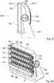
- Fig. 6A the headlight SW is shown again in another illustration, in which the two housing parts GE1 and GE2 are removed.
- Each group GR1,... GR4 of luminous bodies LK have the elongated basic body GK on which the luminous bodies LK are arranged.
- the elongated base bodies of the groups of luminous bodies can be arranged parallel to one another along their longitudinal axes.
- Each luminous element LK is provided with a lens LI for focusing the emitted electromagnetic radiation, which are arranged on a carrier plate TP for each group GR1,... GR4 of luminous bodies LK.
- the carrier plate TP is connected to the elongate base body GK, so that the focus adjustment of the group GR1,... GR4 of luminous bodies LK takes place by varying the distance between the carrier plate TP and the elongated base body GK.
- a first belt RI1 is provided, which is driven by a motor drive and changes the distance between the carrier plate TP and the elongated main body GK via suitable deflection rollers, guides and the like.
- each of the luminous bodies LK is provided with the lens LI which is connected to an LED via an optical conductor LL.
- the heat sink KK On the back of the body GK is the heat sink KK.
- compact luminous bodies LK are created, which can be arranged next to each other on the base body GK to save space.
- the pivotability with respect to the axis of rotation DA can be adjusted individually via a motor control and the emission characteristic can be influenced by means of the lens LI.
- the pivoting with respect to the axis of rotation become.
- a motor control is also provided, which acts on a second belt RI2 on the group GR of the luminous LK. Accordingly, it is possible to influence the electromagnetic radiation emitted by the luminous bodies LK of a group GR, both with regard to the emission angle and the focus area. Accordingly, the illumination field resulting from an illumination of a surface can be selected for each group with regard to a dimension or illumination intensity, so that a uniform illumination can be achieved when the emission angle changes.
- Fig. 7 is the headlight off Fig. 6A shown again in a plan view. It can be seen that the individual basic bodies GK are formed with lenses LI lying next to one another, which are connected via a corresponding motor control, which in Fig. 7 are indicated by the reference numerals SM for the pivoting and ZM for focusing, are individually pivotable.
- the headlight SW is arranged at a fixed distance in front of a vertical wall. If one illuminates the group GR1 of the headlight SW at a first angle the wall of the object and the group GR2 emits at a second angle different from the first angle, both groups would cover a different sized exposure field on the wall of the object without changing the respective focusing , By changing the focus of each group and optionally adjusting the intensity of the light body LK thus the visual impression in each lighting field can be made almost equal.
- a group GR is shown again in a top view.
- the motor control ZM On one side of the body GK the motor control ZM is arranged, the opposite side is provided with a rotation axis DA.
- the supply of light is based on the side view Fig. 8B explained in more detail.
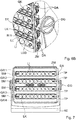
- FIG. 8C A cross-sectional view of a luminous element LK is in Fig. 8C shown.
- the cross section follows a line of intersection perpendicular to the plane along the line AA 'from the Fig. 8A
- the housing GE is designed with the opening OE for supplying cooling air, which reaches the heat sink KK which is in thermal contact with the luminous bodies LK.
- the area inside the headlight SW, which faces this opening OE, is at least splash-proof.
- the interior of the housing GE on the side facing away from the window FE a water-impermeable film-like release layer TF, which eliminates the heat sink KK and thus separates the interior of the housing GE on the side facing the window from the region of the opening OE.
- the separating layer TF is provided in the form of a film which covers the region outside the heat sink KK.
- the separating layer TF is applied between the cooling bodies KK in such a way that an individual pivoting of a group GR of luminous bodies LK is possible.
- the separating layer may be formed with a correspondingly selected oversize in order not to hinder movements of adjacent groups GR of luminous bodies LK.
- the separation layer TF is held in position with a foil holder FH jammed at appropriately selected stops.
- a control unit For programming the emission properties of the headlight SW, a control unit can be provided which can correspondingly change each group of luminous bodies with regard to their geometric, color and spatial radiation.
- This control unit may be connected via an interface with a corresponding programming device, but it is also possible to provide a control panel on the housing of the headlight over which the headlamp can be programmed.
Landscapes
- Engineering & Computer Science (AREA)
- General Engineering & Computer Science (AREA)
- Non-Portable Lighting Devices Or Systems Thereof (AREA)
- Arrangement Of Elements, Cooling, Sealing, Or The Like Of Lighting Devices (AREA)
Claims (12)
- Projecteur pour l'éclairage d'un objet, en particulier d'une façade de bâtiment ou d'une scène, comprenant un boîtier (GE) et une source lumineuse générant un rayonnement électromagnétique perceptible par l'oeil humain, dans lequel la source lumineuse comprend une pluralité de corps lumineux (LK) disposés en plusieurs groupes (GR1, GR2, GR3, GR4), dans lequel chacun des groupes (GR1, GR2, GR3, GR4) de corps lumineux (LK) peut pivoter individuellement par rapport au boîtier de manière à ce que chacun des groupes (GR1, GR2, GR3, GR4) de corps lumineux soit capable d'éclairer l'objet dans un champ d'éclairement associé au groupe (GR1, GR2, GR3, GR4) respectif de corps lumineux (LK), dans lequel les groupes (GR1, GR2, GR3, GR4) de corps lumineux (LK) présentent chacun une focalisation réglable, de manière à ce que des dimensions et/ou des intensités d'éclairement identiques puissent être réglées avec des champs d'éclairement différents sur l'objet à éclairer, dans lequel chacun des groupes (GR1, GR2, GR3, GR4) de corps lumineux (LK) est doté d'un axe de rotation (DA) lui permettant de pivoter et de s'engager dans un support à l'intérieur du boîtier (GE), dans lequel chaque groupe (GR1, GR2, GR3, GR4) de corps lumineux (LK) peut être relié à une unité de commande qui commande chaque groupe (GR1, GR2, GR3, GR4) de corps lumineux (LK) en ce qui concerne l'angle de rayonnement, la longueur d'onde du rayonnement électromagnétique et la focalisation, caractérisé en ce que chaque corps lumineux (LK) est muni d'une lentille (LI) appropriée pour la focalisation du rayonnement électromagnétique projeté, lesquelles lentilles sont disposée sur une plaque de support (TP) pour chaque groupe (GR1, GR2, GR3, GR4) de corps lumineux (TK).
- Projecteur selon la revendication 1, dans lequel le support est réalisé sous la forme d'un châssis.
- Projecteur selon la revendication 1 ou 2, dans lequel deux axes de rotation (DA) sont montés tournants dans le support (RA) sur des côtés opposés du groupe (GR1, GR2, GR3, GR4) de corps lumineux (LK).
- Projecteur selon l'une quelconque des revendications 1 à 3, dans lequel chaque groupe (GR1, GR2, GR3, GR4) de corps lumineux (LK) comporte un corps de base allongé (GK) sur lequel sont disposés les corps lumineux (LK).
- Projecteur selon la revendication 4, dans lequel les corps de base allongés (GK) des groupes (GR1, GR2, GR3, GR4) de corps lumineux (LK) sont disposés parallèlement les uns aux autres suivant leurs axes longitudinaux.
- Projecteur selon la revendication 5, dans lequel la plaque de support (TP) est réglable de manière à ce que la focalisation de chacun des groupes (GR1, GR2, GR3, GR4) de corps lumineux (LK) puisse être réglée par l'intermédiaire de la plaque de support réglable (TP).
- Projecteur selon l'une quelconque des revendications 1 à 6, dans lequel les corps lumineux (LK) sont au moins partiellement réalisés sous la forme de diodes électroluminescentes.
- Projecteur selon l'une quelconque des revendications 1 à 7, dans lequel le boîtier (GE) entoure le support et dans lequel le support (RA) est relié tournant à un élément d'installation (AE).
- Projecteur selon la revendication 8, dans lequel le boîtier (GE) est constitué de plusieurs parties, en particulier de deux parties et dans lequel les parties du boîtier (GE) peuvent être remplacées.
- Projecteur selon l'une quelconque des revendications 1 à 9, dans lequel le boîtier (GE) comporte sur sa face avant une fenêtre (FE) pouvant être traversée par un rayonnement électromagnétique.
- Projecteur selon la revendication 10, dans lequel le boîtier (GE) est pourvu d'une ouverture (OE) permettant l'introduction d'air de refroidissement pouvant être acheminé vers des dissipateurs thermiques (KK) en contact thermique avec les corps lumineux (LK).
- Projecteur selon la revendication 11, dans lequel l'intérieur du boîtier (GE) présente, du côté tourné en sens opposé à la fenêtre (FE), une couche de séparation (TF) imperméable à l'eau qui encadre les dissipateurs thermiques (KK) et sépare l'intérieur du boîtier (GE) de la zone de l'ouverture (OE), sur la face qui est tournée vers la fenêtre (FE).
Applications Claiming Priority (1)
| Application Number | Priority Date | Filing Date | Title |
|---|---|---|---|
| DE102015105592.9A DE102015105592A1 (de) | 2015-04-13 | 2015-04-13 | Scheinwerfer |
Publications (2)
| Publication Number | Publication Date |
|---|---|
| EP3081855A1 EP3081855A1 (fr) | 2016-10-19 |
| EP3081855B1 true EP3081855B1 (fr) | 2019-03-20 |
Family
ID=55650197
Family Applications (1)
| Application Number | Title | Priority Date | Filing Date |
|---|---|---|---|
| EP16162060.4A Active EP3081855B1 (fr) | 2015-04-13 | 2016-03-23 | Projecteur |
Country Status (3)
| Country | Link |
|---|---|
| EP (1) | EP3081855B1 (fr) |
| DE (1) | DE102015105592A1 (fr) |
| DK (1) | DK3081855T3 (fr) |
Families Citing this family (2)
| Publication number | Priority date | Publication date | Assignee | Title |
|---|---|---|---|---|
| DE102017103219A1 (de) * | 2017-02-16 | 2018-08-16 | Osram Oled Gmbh | Beleuchtungseinrichtung, Verfahren zur Beleuchtung und Beleuchtungsanlage |
| CN111396820B (zh) * | 2020-03-24 | 2021-06-15 | 宁波甜宝生物信息技术有限公司 | 一种可调式的led洗墙灯 |
Citations (2)
| Publication number | Priority date | Publication date | Assignee | Title |
|---|---|---|---|---|
| US20100296285A1 (en) * | 2008-04-14 | 2010-11-25 | Digital Lumens, Inc. | Fixture with Rotatable Light Modules |
| FR2988464A1 (fr) * | 2012-03-20 | 2013-09-27 | Ayrton | Dispositif lumineux comprenant un projecteur compose d'une pluralite de sources lumineuses |
Family Cites Families (13)
| Publication number | Priority date | Publication date | Assignee | Title |
|---|---|---|---|---|
| SM200600005B (it) * | 2006-02-15 | 2007-08-22 | Idealed.It S R L | Unita' luminosa led ad alta potenza, nonche' apparato di illuminazione comprendente tale unita' |
| US7614766B2 (en) * | 2006-06-29 | 2009-11-10 | Harvatek Corporation | Modular illumination device with adjustable lighting angles |
| ITPR20070078A1 (it) * | 2007-10-16 | 2009-04-17 | Coemar Spa | Proiettore per illuminazione di superfici e generazione di effetti luminosi |
| EP2201289A4 (fr) * | 2007-10-24 | 2012-06-06 | Lsi Industries Inc | Appareil d'éclairage ajustable |
| DE102008021538A1 (de) * | 2008-04-30 | 2009-11-05 | Torsten Kracht | Dreh- und schwenkbare Lampeneinheit |
| US8197115B2 (en) * | 2008-12-30 | 2012-06-12 | Dean Andrew Wilkinson | Luminaire with adjustable light source |
| AT509179B1 (de) * | 2009-11-26 | 2011-10-15 | Hierzer Andreas | Schwenkbare led einbauleuchte mit geringer einbauhöhe |
| DE202010001465U1 (de) * | 2010-01-28 | 2010-04-22 | Franz Sill Gmbh | LED-Fassadenstrahler |
| FR2981432A1 (fr) * | 2011-10-14 | 2013-04-19 | Ayrton | Dispositif lumineux comprenant un chassis et un projecteur pivotant |
| DE102012204307B4 (de) * | 2012-03-19 | 2013-12-24 | B & K Braun Gmbh | Scheinwerfer und Verfahren zum Herstellen eines Scheinwerfers |
| DE202012103660U1 (de) * | 2012-09-24 | 2014-01-07 | Cobra Electronic Gmbh & Co. Kg | Leuchte, insbesondere Scheinwerfer |
| US9695993B2 (en) * | 2013-04-26 | 2017-07-04 | Main Harbour International Limited | Long distance high intensity LED light with adjustable focus |
| CN105637289B (zh) * | 2013-10-05 | 2019-11-26 | 哈曼专业丹麦公司 | 具有旋转变焦透镜的照明装置 |
-
2015
- 2015-04-13 DE DE102015105592.9A patent/DE102015105592A1/de not_active Withdrawn
-
2016
- 2016-03-23 DK DK16162060.4T patent/DK3081855T3/da active
- 2016-03-23 EP EP16162060.4A patent/EP3081855B1/fr active Active
Patent Citations (2)
| Publication number | Priority date | Publication date | Assignee | Title |
|---|---|---|---|---|
| US20100296285A1 (en) * | 2008-04-14 | 2010-11-25 | Digital Lumens, Inc. | Fixture with Rotatable Light Modules |
| FR2988464A1 (fr) * | 2012-03-20 | 2013-09-27 | Ayrton | Dispositif lumineux comprenant un projecteur compose d'une pluralite de sources lumineuses |
Also Published As
| Publication number | Publication date |
|---|---|
| EP3081855A1 (fr) | 2016-10-19 |
| DE102015105592A1 (de) | 2016-10-13 |
| DK3081855T3 (da) | 2019-06-11 |
Similar Documents
| Publication | Publication Date | Title |
|---|---|---|
| EP2411728B1 (fr) | Support comportant au moins un dispositif d'éclairage à semi-conducteur et système de support | |
| AT519084A2 (de) | Leuchte | |
| EP2239494A1 (fr) | Agencement destiné à l'éclairage ambiant | |
| DE102007059607A1 (de) | Wand- und/oder Deckenleuchte | |
| DE202010017320U1 (de) | Steh- oder Tischleuchte | |
| EP2031295A1 (fr) | Eclairage d'examen médical, en particulier dentaire | |
| DE102010002389A1 (de) | Grundträger, Lichtquellenträger und System aus Grundträger und Lichtquellenträger | |
| DE202017005050U1 (de) | Beleuchtungsvorrichtung | |
| EP3081855B1 (fr) | Projecteur | |
| WO2007122113A1 (fr) | Système d'éclairage modulaire et ensemble d'éclairage | |
| EP2333404A1 (fr) | Projecteur lumineux avec diffuseur | |
| EP2988062B1 (fr) | Luminaire | |
| DE102008017271B4 (de) | Leuchte mit zwei Lichtquellen in einer Aussparung eines zumindest teilweise lichtleitenden Trägers, Verwendung dieser Leuchte als Hänge-, Wand- oder Standleuchte und Leuchtvorrichtung für eine solche Leuchte | |
| DE102007009229A1 (de) | Lichtquelle zur Simulation einer Punktlichtquelle, sowie Leuchte mit einer derartigen Lichtquelle | |
| DE102016120256A1 (de) | Beleuchtungsvorrichtung mit variabler lichtverteilung | |
| EP3583353B1 (fr) | Projecteur à del de haute performance, et système de projection comprenant ce projecteur pour éclairer des terrains sportifs | |
| DE19919080A1 (de) | Beleuchtungseinrichtung | |
| EP1530404B1 (fr) | Emetteur de lumière et de chaleur | |
| EP2989378B1 (fr) | Lampe à led à distributions lumineuses réglables | |
| EP2636948B1 (fr) | Lampe DEL et procédé de fonctionnement d'une telle lampe | |
| DE102010006248B3 (de) | LED-Fassadenstrahler | |
| DE202010001465U1 (de) | LED-Fassadenstrahler | |
| EP3910233B1 (fr) | Luminaire | |
| DE202011108791U1 (de) | Optik für eine Halbleiterleuchtvorrichtung | |
| EP3473916B1 (fr) | Luminaire pourvu d'unité d'éclairage ainsi qu'une couverture entourant l'unité d'éclairage |
Legal Events
| Date | Code | Title | Description |
|---|---|---|---|
| PUAI | Public reference made under article 153(3) epc to a published international application that has entered the european phase |
Free format text: ORIGINAL CODE: 0009012 |
|
| AK | Designated contracting states |
Kind code of ref document: A1 Designated state(s): AL AT BE BG CH CY CZ DE DK EE ES FI FR GB GR HR HU IE IS IT LI LT LU LV MC MK MT NL NO PL PT RO RS SE SI SK SM TR |
|
| AX | Request for extension of the european patent |
Extension state: BA ME |
|
| STAA | Information on the status of an ep patent application or granted ep patent |
Free format text: STATUS: REQUEST FOR EXAMINATION WAS MADE |
|
| 17P | Request for examination filed |
Effective date: 20170419 |
|
| RBV | Designated contracting states (corrected) |
Designated state(s): AL AT BE BG CH CY CZ DE DK EE ES FI FR GB GR HR HU IE IS IT LI LT LU LV MC MK MT NL NO PL PT RO RS SE SI SK SM TR |
|
| STAA | Information on the status of an ep patent application or granted ep patent |
Free format text: STATUS: EXAMINATION IS IN PROGRESS |
|
| 17Q | First examination report despatched |
Effective date: 20170821 |
|
| RIC1 | Information provided on ipc code assigned before grant |
Ipc: F21Y 103/10 20160101ALN20180905BHEP Ipc: F21W 131/107 20060101ALN20180905BHEP Ipc: F21V 21/30 20060101ALI20180905BHEP Ipc: F21V 14/06 20060101ALI20180905BHEP Ipc: F21Y 113/00 20160101ALN20180905BHEP Ipc: F21V 14/02 20060101AFI20180905BHEP Ipc: F21Y 115/10 20160101ALN20180905BHEP |
|
| GRAP | Despatch of communication of intention to grant a patent |
Free format text: ORIGINAL CODE: EPIDOSNIGR1 |
|
| STAA | Information on the status of an ep patent application or granted ep patent |
Free format text: STATUS: GRANT OF PATENT IS INTENDED |
|
| INTG | Intention to grant announced |
Effective date: 20181012 |
|
| GRAS | Grant fee paid |
Free format text: ORIGINAL CODE: EPIDOSNIGR3 |
|
| GRAA | (expected) grant |
Free format text: ORIGINAL CODE: 0009210 |
|
| STAA | Information on the status of an ep patent application or granted ep patent |
Free format text: STATUS: THE PATENT HAS BEEN GRANTED |
|
| AK | Designated contracting states |
Kind code of ref document: B1 Designated state(s): AL AT BE BG CH CY CZ DE DK EE ES FI FR GB GR HR HU IE IS IT LI LT LU LV MC MK MT NL NO PL PT RO RS SE SI SK SM TR |
|
| REG | Reference to a national code |
Ref country code: GB Ref legal event code: FG4D Free format text: NOT ENGLISH |
|
| REG | Reference to a national code |
Ref country code: CH Ref legal event code: EP |
|
| REG | Reference to a national code |
Ref country code: DE Ref legal event code: R096 Ref document number: 502016003784 Country of ref document: DE |
|
| REG | Reference to a national code |
Ref country code: AT Ref legal event code: REF Ref document number: 1110923 Country of ref document: AT Kind code of ref document: T Effective date: 20190415 |
|
| REG | Reference to a national code |
Ref country code: IE Ref legal event code: FG4D Free format text: LANGUAGE OF EP DOCUMENT: GERMAN |
|
| REG | Reference to a national code |
Ref country code: DK Ref legal event code: T3 Effective date: 20190607 |
|
| REG | Reference to a national code |
Ref country code: NL Ref legal event code: FP |
|
| PG25 | Lapsed in a contracting state [announced via postgrant information from national office to epo] |
Ref country code: NO Free format text: LAPSE BECAUSE OF FAILURE TO SUBMIT A TRANSLATION OF THE DESCRIPTION OR TO PAY THE FEE WITHIN THE PRESCRIBED TIME-LIMIT Effective date: 20190620 Ref country code: FI Free format text: LAPSE BECAUSE OF FAILURE TO SUBMIT A TRANSLATION OF THE DESCRIPTION OR TO PAY THE FEE WITHIN THE PRESCRIBED TIME-LIMIT Effective date: 20190320 Ref country code: SE Free format text: LAPSE BECAUSE OF FAILURE TO SUBMIT A TRANSLATION OF THE DESCRIPTION OR TO PAY THE FEE WITHIN THE PRESCRIBED TIME-LIMIT Effective date: 20190320 Ref country code: LT Free format text: LAPSE BECAUSE OF FAILURE TO SUBMIT A TRANSLATION OF THE DESCRIPTION OR TO PAY THE FEE WITHIN THE PRESCRIBED TIME-LIMIT Effective date: 20190320 |
|
| REG | Reference to a national code |
Ref country code: LT Ref legal event code: MG4D |
|
| PG25 | Lapsed in a contracting state [announced via postgrant information from national office to epo] |
Ref country code: HR Free format text: LAPSE BECAUSE OF FAILURE TO SUBMIT A TRANSLATION OF THE DESCRIPTION OR TO PAY THE FEE WITHIN THE PRESCRIBED TIME-LIMIT Effective date: 20190320 Ref country code: RS Free format text: LAPSE BECAUSE OF FAILURE TO SUBMIT A TRANSLATION OF THE DESCRIPTION OR TO PAY THE FEE WITHIN THE PRESCRIBED TIME-LIMIT Effective date: 20190320 Ref country code: LV Free format text: LAPSE BECAUSE OF FAILURE TO SUBMIT A TRANSLATION OF THE DESCRIPTION OR TO PAY THE FEE WITHIN THE PRESCRIBED TIME-LIMIT Effective date: 20190320 Ref country code: GR Free format text: LAPSE BECAUSE OF FAILURE TO SUBMIT A TRANSLATION OF THE DESCRIPTION OR TO PAY THE FEE WITHIN THE PRESCRIBED TIME-LIMIT Effective date: 20190621 Ref country code: BG Free format text: LAPSE BECAUSE OF FAILURE TO SUBMIT A TRANSLATION OF THE DESCRIPTION OR TO PAY THE FEE WITHIN THE PRESCRIBED TIME-LIMIT Effective date: 20190620 |
|
| PG25 | Lapsed in a contracting state [announced via postgrant information from national office to epo] |
Ref country code: EE Free format text: LAPSE BECAUSE OF FAILURE TO SUBMIT A TRANSLATION OF THE DESCRIPTION OR TO PAY THE FEE WITHIN THE PRESCRIBED TIME-LIMIT Effective date: 20190320 Ref country code: RO Free format text: LAPSE BECAUSE OF FAILURE TO SUBMIT A TRANSLATION OF THE DESCRIPTION OR TO PAY THE FEE WITHIN THE PRESCRIBED TIME-LIMIT Effective date: 20190320 Ref country code: AL Free format text: LAPSE BECAUSE OF FAILURE TO SUBMIT A TRANSLATION OF THE DESCRIPTION OR TO PAY THE FEE WITHIN THE PRESCRIBED TIME-LIMIT Effective date: 20190320 Ref country code: ES Free format text: LAPSE BECAUSE OF FAILURE TO SUBMIT A TRANSLATION OF THE DESCRIPTION OR TO PAY THE FEE WITHIN THE PRESCRIBED TIME-LIMIT Effective date: 20190320 Ref country code: PT Free format text: LAPSE BECAUSE OF FAILURE TO SUBMIT A TRANSLATION OF THE DESCRIPTION OR TO PAY THE FEE WITHIN THE PRESCRIBED TIME-LIMIT Effective date: 20190720 Ref country code: SK Free format text: LAPSE BECAUSE OF FAILURE TO SUBMIT A TRANSLATION OF THE DESCRIPTION OR TO PAY THE FEE WITHIN THE PRESCRIBED TIME-LIMIT Effective date: 20190320 |
|
| REG | Reference to a national code |
Ref country code: CH Ref legal event code: PL |
|
| PG25 | Lapsed in a contracting state [announced via postgrant information from national office to epo] |
Ref country code: PL Free format text: LAPSE BECAUSE OF FAILURE TO SUBMIT A TRANSLATION OF THE DESCRIPTION OR TO PAY THE FEE WITHIN THE PRESCRIBED TIME-LIMIT Effective date: 20190320 Ref country code: SM Free format text: LAPSE BECAUSE OF FAILURE TO SUBMIT A TRANSLATION OF THE DESCRIPTION OR TO PAY THE FEE WITHIN THE PRESCRIBED TIME-LIMIT Effective date: 20190320 Ref country code: LU Free format text: LAPSE BECAUSE OF NON-PAYMENT OF DUE FEES Effective date: 20190323 |
|
| REG | Reference to a national code |
Ref country code: BE Ref legal event code: MM Effective date: 20190331 |
|
| PG25 | Lapsed in a contracting state [announced via postgrant information from national office to epo] |
Ref country code: IS Free format text: LAPSE BECAUSE OF FAILURE TO SUBMIT A TRANSLATION OF THE DESCRIPTION OR TO PAY THE FEE WITHIN THE PRESCRIBED TIME-LIMIT Effective date: 20190720 |
|
| REG | Reference to a national code |
Ref country code: DE Ref legal event code: R097 Ref document number: 502016003784 Country of ref document: DE |
|
| PLBE | No opposition filed within time limit |
Free format text: ORIGINAL CODE: 0009261 |
|
| STAA | Information on the status of an ep patent application or granted ep patent |
Free format text: STATUS: NO OPPOSITION FILED WITHIN TIME LIMIT |
|
| PG25 | Lapsed in a contracting state [announced via postgrant information from national office to epo] |
Ref country code: CH Free format text: LAPSE BECAUSE OF NON-PAYMENT OF DUE FEES Effective date: 20190331 Ref country code: IE Free format text: LAPSE BECAUSE OF NON-PAYMENT OF DUE FEES Effective date: 20190323 Ref country code: LI Free format text: LAPSE BECAUSE OF NON-PAYMENT OF DUE FEES Effective date: 20190331 Ref country code: MC Free format text: LAPSE BECAUSE OF FAILURE TO SUBMIT A TRANSLATION OF THE DESCRIPTION OR TO PAY THE FEE WITHIN THE PRESCRIBED TIME-LIMIT Effective date: 20190320 |
|
| 26N | No opposition filed |
Effective date: 20200102 |
|
| PG25 | Lapsed in a contracting state [announced via postgrant information from national office to epo] |
Ref country code: BE Free format text: LAPSE BECAUSE OF NON-PAYMENT OF DUE FEES Effective date: 20190331 Ref country code: SI Free format text: LAPSE BECAUSE OF FAILURE TO SUBMIT A TRANSLATION OF THE DESCRIPTION OR TO PAY THE FEE WITHIN THE PRESCRIBED TIME-LIMIT Effective date: 20190320 |
|
| PG25 | Lapsed in a contracting state [announced via postgrant information from national office to epo] |
Ref country code: TR Free format text: LAPSE BECAUSE OF FAILURE TO SUBMIT A TRANSLATION OF THE DESCRIPTION OR TO PAY THE FEE WITHIN THE PRESCRIBED TIME-LIMIT Effective date: 20190320 |
|
| PG25 | Lapsed in a contracting state [announced via postgrant information from national office to epo] |
Ref country code: MT Free format text: LAPSE BECAUSE OF FAILURE TO SUBMIT A TRANSLATION OF THE DESCRIPTION OR TO PAY THE FEE WITHIN THE PRESCRIBED TIME-LIMIT Effective date: 20190320 |
|
| PG25 | Lapsed in a contracting state [announced via postgrant information from national office to epo] |
Ref country code: CY Free format text: LAPSE BECAUSE OF FAILURE TO SUBMIT A TRANSLATION OF THE DESCRIPTION OR TO PAY THE FEE WITHIN THE PRESCRIBED TIME-LIMIT Effective date: 20190320 |
|
| PG25 | Lapsed in a contracting state [announced via postgrant information from national office to epo] |
Ref country code: HU Free format text: LAPSE BECAUSE OF FAILURE TO SUBMIT A TRANSLATION OF THE DESCRIPTION OR TO PAY THE FEE WITHIN THE PRESCRIBED TIME-LIMIT; INVALID AB INITIO Effective date: 20160323 |
|
| PG25 | Lapsed in a contracting state [announced via postgrant information from national office to epo] |
Ref country code: MK Free format text: LAPSE BECAUSE OF FAILURE TO SUBMIT A TRANSLATION OF THE DESCRIPTION OR TO PAY THE FEE WITHIN THE PRESCRIBED TIME-LIMIT Effective date: 20190320 |
|
| PGFP | Annual fee paid to national office [announced via postgrant information from national office to epo] |
Ref country code: FR Payment date: 20230322 Year of fee payment: 8 Ref country code: DK Payment date: 20230321 Year of fee payment: 8 |
|
| PGFP | Annual fee paid to national office [announced via postgrant information from national office to epo] |
Ref country code: IT Payment date: 20230329 Year of fee payment: 8 |
|
| PGFP | Annual fee paid to national office [announced via postgrant information from national office to epo] |
Ref country code: NL Payment date: 20240320 Year of fee payment: 9 |
|
| PGFP | Annual fee paid to national office [announced via postgrant information from national office to epo] |
Ref country code: AT Payment date: 20240318 Year of fee payment: 9 |
|
| PGFP | Annual fee paid to national office [announced via postgrant information from national office to epo] |
Ref country code: DE Payment date: 20240331 Year of fee payment: 9 Ref country code: CZ Payment date: 20240308 Year of fee payment: 9 Ref country code: GB Payment date: 20240322 Year of fee payment: 9 |