EP3081518A1 - Textilmaschine - Google Patents
Textilmaschine Download PDFInfo
- Publication number
- EP3081518A1 EP3081518A1 EP16164026.3A EP16164026A EP3081518A1 EP 3081518 A1 EP3081518 A1 EP 3081518A1 EP 16164026 A EP16164026 A EP 16164026A EP 3081518 A1 EP3081518 A1 EP 3081518A1
- Authority
- EP
- European Patent Office
- Prior art keywords
- package
- yarn
- catching
- textile machine
- winding drum
- Prior art date
- Legal status (The legal status is an assumption and is not a legal conclusion. Google has not performed a legal analysis and makes no representation as to the accuracy of the status listed.)
- Granted
Links
- 239000004753 textile Substances 0.000 title claims description 37
- 238000004804 winding Methods 0.000 claims description 99
- 230000007246 mechanism Effects 0.000 claims description 29
- 238000009987 spinning Methods 0.000 description 79
- 230000009471 action Effects 0.000 description 15
- 230000001276 controlling effect Effects 0.000 description 10
- 230000007547 defect Effects 0.000 description 10
- 230000002093 peripheral effect Effects 0.000 description 5
- 238000001514 detection method Methods 0.000 description 4
- 239000000835 fiber Substances 0.000 description 4
- 230000009467 reduction Effects 0.000 description 4
- 238000010586 diagram Methods 0.000 description 3
- 238000003780 insertion Methods 0.000 description 3
- 230000037431 insertion Effects 0.000 description 3
- 238000011144 upstream manufacturing Methods 0.000 description 3
- 238000003825 pressing Methods 0.000 description 2
- 230000015572 biosynthetic process Effects 0.000 description 1
- 238000010276 construction Methods 0.000 description 1
- 238000000034 method Methods 0.000 description 1
- 238000012986 modification Methods 0.000 description 1
- 230000004048 modification Effects 0.000 description 1
- 238000007383 open-end spinning Methods 0.000 description 1
- 230000001105 regulatory effect Effects 0.000 description 1
Images





Classifications
-
- B—PERFORMING OPERATIONS; TRANSPORTING
- B65—CONVEYING; PACKING; STORING; HANDLING THIN OR FILAMENTARY MATERIAL
- B65H—HANDLING THIN OR FILAMENTARY MATERIAL, e.g. SHEETS, WEBS, CABLES
- B65H67/00—Replacing or removing cores, receptacles, or completed packages at paying-out, winding, or depositing stations
- B65H67/08—Automatic end-finding and material-interconnecting arrangements
- B65H67/081—Automatic end-finding and material-interconnecting arrangements acting after interruption of the winding process, e.g. yarn breakage, yarn cut or package replacement
- B65H67/085—Automatic end-finding and material-interconnecting arrangements acting after interruption of the winding process, e.g. yarn breakage, yarn cut or package replacement end-finding at the take-up package, e.g. by suction and reverse package rotation
-
- D—TEXTILES; PAPER
- D01—NATURAL OR MAN-MADE THREADS OR FIBRES; SPINNING
- D01H—SPINNING OR TWISTING
- D01H15/00—Piecing arrangements ; Automatic end-finding, e.g. by suction and reverse package rotation; Devices for temporarily storing yarn during piecing
-
- B—PERFORMING OPERATIONS; TRANSPORTING
- B65—CONVEYING; PACKING; STORING; HANDLING THIN OR FILAMENTARY MATERIAL
- B65H—HANDLING THIN OR FILAMENTARY MATERIAL, e.g. SHEETS, WEBS, CABLES
- B65H63/00—Warning or safety devices, e.g. automatic fault detectors, stop-motions ; Quality control of the package
- B65H63/02—Warning or safety devices, e.g. automatic fault detectors, stop-motions ; Quality control of the package responsive to reduction in material tension, failure of supply, or breakage, of material
- B65H63/024—Warning or safety devices, e.g. automatic fault detectors, stop-motions ; Quality control of the package responsive to reduction in material tension, failure of supply, or breakage, of material responsive to breakage of materials
- B65H63/036—Warning or safety devices, e.g. automatic fault detectors, stop-motions ; Quality control of the package responsive to reduction in material tension, failure of supply, or breakage, of material responsive to breakage of materials characterised by the combination of the detecting or sensing elements with other devices, e.g. stopping devices for material advancing or winding mechanism
- B65H63/0364—Warning or safety devices, e.g. automatic fault detectors, stop-motions ; Quality control of the package responsive to reduction in material tension, failure of supply, or breakage, of material responsive to breakage of materials characterised by the combination of the detecting or sensing elements with other devices, e.g. stopping devices for material advancing or winding mechanism by lifting or raising the package away from the driving roller
-
- D—TEXTILES; PAPER
- D01—NATURAL OR MAN-MADE THREADS OR FIBRES; SPINNING
- D01H—SPINNING OR TWISTING
- D01H4/00—Open-end spinning machines or arrangements for imparting twist to independently moving fibres separated from slivers; Piecing arrangements therefor; Covering endless core threads with fibres by open-end spinning techniques
- D01H4/48—Piecing arrangements; Control therefor
-
- B—PERFORMING OPERATIONS; TRANSPORTING
- B65—CONVEYING; PACKING; STORING; HANDLING THIN OR FILAMENTARY MATERIAL
- B65H—HANDLING THIN OR FILAMENTARY MATERIAL, e.g. SHEETS, WEBS, CABLES
- B65H2701/00—Handled material; Storage means
- B65H2701/30—Handled filamentary material
- B65H2701/31—Textiles threads or artificial strands of filaments
Definitions
- the present invention relates to a textile machine that forms a package. Specifically, the present invention relates to a configuration that can surely catch a yarn end of a package when performing yarn joining work and the like.
- the spinning frame disclosed in Japanese Patent Laid-Open No. 2010-189083 includes a suction mouth, a cradle arm, and a package plate.
- the suction mouth catches the yarn end of the package and guides the yarn end to a yarn joining device and the like.
- the cradle arm rotatably supports the package, and pivotably supports the package so that the package can be moved by pivoting the cradle arm.
- the package plate is caused to contact the package when stopping the rotation of the package.
- the package plate when performing yarn joining due to occurrence of a yarn defect and the like, the package plate is pressed against the package to move the package away from the suction mouth so that the surface of the package is positioned at the same position every time. After the surface of the package has been positioned in this manner, the suction mouth is brought close to the surface of the package and a catching operation of catching the yarn end is performed.
- a textile machine includes a first catching member that performs a catching operation of catching a yarn end of a package; a cradle arm that rotatably supports the package and also movably supports the package so that the package is movable in a separating direction in which the package moves away from the first catching member; a driving mechanism that drives the cradle arm to move the package in the separating direction; and a controlling section that controls the driving mechanism to move the package in the separating direction after causing a surface of the package and the first catching member to contact each other, and provides a control so that the first catching member performs the catching operation in the state in which the surface of the package and the first catching member are separated from each other.
- upstream and downstream respectively mean upstream and downstream in a traveling direction of a yarn when spinning is performed.
- a spinning frame 1 which is an example of the textile machine, shown in FIG. 1 , includes a large number of spinning units (winding units) 2 that are arranged side-by-side.
- the spinning frame 1 also includes a yarn joining cart (work cart) 3, a blower box 80, and a motor box 5.
- each spinning unit 2 mainly includes a drafting device 7, a spinning device (yarn supplying section) 9, a yarn feeding device 11, a yarn-slack removing device 12, and a winding device 13 arranged in this order from the upstream to the downstream.
- the drafting device 7 is arranged near an upper edge of a frame 6 of the spinning frame 1.
- a fiber bundle 8 that is fed by the drafting device 7 is spun by the spinning device 9.
- a spun yarn 10 formed in the spinning device 9 is fed by the yarn feeding device 11 and subsequently wound by the winding device 13 on a bobbin 48 thereby forming a package 45.
- the drafting device 7 is a device that draws a fiber bundle called a sliver 15 to form the fiber bundle 8 that is thin.
- the drafting device 7 includes, as shown in FIG. 2 , four roller pairs, namely, a back roller pair 16, a third roller pair 17, a middle roller pair 19 with an apron belt 18 stretched over each roller thereof, and a front roller pair 20.
- the spinning device 9 Although a detailed configuration of the spinning device 9 is not shown, an air spinning device that uses a swirling air current to apply twists to the fiber bundle 8 to form the spun yarn 10 has been adopted in the present embodiment.
- the yarn feeding device 11 includes a delivery roller 39 supported by the frame 6 of the spinning frame 1, and a nip roller 40 arranged in contact with the delivery roller 39.
- the spun yarn 10 fed out from the spinning device 9 is pinched between the delivery roller 39 and the nip roller 40.
- the spun yarn 10 can be fed to the winding device 13 by rotationally driving the delivery roller 39 with a not-shown electric motor.
- the yarn-slack removing device 12 is arranged downstream of the yarn feeding device 11.
- the yarn-slack removing device 12 includes a slack removing roller 21, a yarn hooking member 22, and an electric motor 25.
- the yarn hooking member 22 is engageable with (hook) the spun yarn 10.
- the spun yarn 10 can be guided to an outer peripheral surface of the slack removing roller 21.
- the slack removing roller 21 functions to accumulate the spun yarn 10 wound around the outer peripheral surface thereof.
- the slack removing roller 21 is rotationally driven by the electric motor 25. Accordingly, the spun yarn 10 can be temporarily accumulated in the yarn-slack removing device 12 that is arranged between the yarn feeding device 11 and the winding device 13.
- a yarn-defect detecting device 52 is arranged in a front portion of the frame 6 of the spinning frame 1 but between the yarn feeding device 11 and the yarn-slack removing device 12.
- the spun yarn 10 formed in the spinning device 9 passes by / through the yarn-defect detecting device 52 before the spun yarn 10 is wound in the yarn-slack removing device 12.
- the yarn-defect detecting device 52 monitors a thickness and the like of the traveling spun yarn 10.
- the yarn-defect detecting device 52 transmits a yarn-defect detection signal to a unit controller (a controlling section) 92 (see FIG. 3 ).
- the unit controller 92 is a computer that controls the spinning unit 2.
- a cutter 57 is arranged near the yarn-defect detecting device 52 to cut the spun yarn 10 when a yarn defect is detected in the spun yarn 10.
- the winding device 13 mainly includes a cradle arm 71, a winding drum 72, and a traversing device 75.
- the winding drum 72 can be driven while being in contact with an outer peripheral surface of the bobbin 48 or the package 45.
- the traversing device 75 includes a traversing guide 76 capable of guiding the spun yarn 10.
- the traversing guide 76 is caused to make a reciprocating movement by a not-shown driving means (this driving means is shared by a large number of the spinning units in the present embodiment) while the winding drum 72 is being driven by a not-shown electric motor.
- a not-shown driving means this driving means is shared by a large number of the spinning units in the present embodiment
- the cradle arm 71 rotatably supports the bobbin 48 on which the spun yarn 10 is wound.
- the cradle arm 71 is pivotably supported by a support shaft 70. Accordingly, the cradle arm 71 can be pivoted in both of a direction in which the package 45 moves toward the winding drum 72 and a direction in which the package 45 moves away from the winding drum 72. With this arrangement, even if a diameter of a yarn layer on the package 45 increases as winding of the spun yarn 10 thereon advances, the increase in the diameter of the yarn layer can be absorbed by pivoting the cradle arm 71, and the surface of the package 45 can be continued to appropriately contact the winding drum 72.
- the package 45 In a state in which a tip end section of a suction mouth 46, which is installed in the later-explained yarn joining cart 3, is brought close to the package 45, the package 45 can be moved toward the suction mouth 46 (may be called “an approaching direction” below) or can be moved away from the suction mouth 46 (may be called “a separating direction” below) by pivoting the cradle arm 71.
- An air cylinder (a driving mechanism) 60 is coupled to the cradle arm 71.
- the air cylinder 60 is constructed as a double-acting air cylinder and includes a piston rod 61, a piston 62 fixed to the piston rod 61, a contact-pressure port 63, and a back-pressure port 64.
- compressed air (may be simply called “air” below) is supplied from the contact-pressure port 63 and the back-pressure port 64 in a cylinder casing of the air cylinder 60.
- air When there is a difference in air pressures in the air supplied from the contact-pressure port 63 and the air supplied from the back-pressure port 64, the air pushes the piston 62 whereby the piston rod 61 is driven.
- the piston rod 61 is coupled to the cradle arm 71.
- the contact-pressure port 63 is connected to a compressed-air source for press-contact 65 that is arranged in the blower box 80.
- this air supplied in the cylinder casing from the contact-pressure port 63 pushes the piston 62 whereby the piston rod 61 pulls the cradle arm 71.
- a force (torque) that causes the cradle arm 71 to pivot whereby the package 45 is pressed against the winding drum 72 is generated.
- the back-pressure port 64 is connected to a back-pressure-port connection port 81 of a three-port valve 66.
- the three-port valve 66 is constructed as a solenoid valve and includes the back-pressure-port connection port 81, a pressure-reduction-valve connection port 82, and a drain port 83.
- a valve element of the three-port valve 66 is switchable between a position (an open position shown in FIG. 2 ) at which the back-pressure-port connection port 81 is connected to the drain port 83 and the pressure-reduction-valve connection port 82 is closed and a position (a connecting position shown in FIG. 5 ) in which the back-pressure-port connection port 81 is connected to the pressure-reduction-valve connection port 82.
- a pressure reduction valve 67 is connected to the pressure-reduction-valve connection port 82, and the drain port 83 is set at the atmospheric pressure.
- the valve element of the three-port valve 66 is arranged in the open position whereby the back-pressure-port connection port 81 is connected to the drain port 83.
- this state may be referred to as an open state. Because the back-pressure port 64 is set at the atmospheric pressure in this open state, the air pressure of only the compressed-air source for press-contact 65 acts on the piston 62. As a result, the package 45 can be pressed by a sufficient pressing force against the winding drum 72 whereby the package 45 can be rotationally driven stably by the winding drum 72.
- the back-pressure port 64 is connected to the pressure reduction valve 67.
- this state may be referred to as a connected state.
- the pressure reduction valve 67 is connected to the compressed-air source for press-contact 65.
- the pressure reduction valve 67 reduces the pressure of the air supplied by the compressed-air source for press-contact 65, and the reduced-pressure air is supplied to the pressure-reduction-valve connection port 82.
- air at a lower pressure than the pressure of the air supplied to the contact-pressure port 63 can be supplied to the back-pressure port 64.
- the air supplied to the back-pressure port 64 offsets the air supplied to the contact-pressure port 63 to some extent, the force (torque) applied to the cradle arm 71 is reduced, whereby the package 45 can be caused to contact the winding drum 72 at a reduced force (pressing force).
- the three-port valve 66 is electrically connected to the unit controller 92.
- the unit controller 92 can switch the three-port valve 66 between the open state and the connected state by transmitting a control signal to the three-port valve 66.
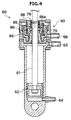
- the air cylinder 60 has a lifter part 90.
- the lifter part 90 mainly includes a lifter port 68, a lifter piston 85, a tapering member 86, balls 87, and a spring 88.
- a compressed-air source for lifter 69 that supplies compressed air to the lifter part 90 is connected to the lifter port 68.
- a solenoid valve 91 (a valve similar to the three-port valve 66) shown in FIG. 3 is arranged between the lifter port 68 and the compressed-air source for lifter 69. Compressed air can be supplied to the lifter port 68 or compressed air can be released from the lifter port 68 by appropriately operating this solenoid valve 91.
- a state in which no air is supplied to the lifter port 68 is shown in FIG. 2 . That is, a state in which the compressed air is released from the lifter port 68 is shown with a dotted line in FIG. 2 .
- a state in which air is supplied to the lifter port 68 is shown with a solid line arrow in FIG. 5 .
- the lifter piston 85 is arranged in the lifter part 90 so as to be movable by a predetermined stroke in a longitudinal direction of the piston rod 61.
- the lifter piston 85 and the tapering member 86 are biased, as shown in FIG. 4 , in a downward direction in the figure by the spring 88.
- the piston rod 61 can move freely in the upward-downward direction in the figure.
- the lifter piston 85 and the tapering member 86 are driven upward in FIG. 4 by the action of the air.
- an insertion hole through which the piston rod 61 is passed and can be moved upward-downward is formed in the tapering member 86.
- the insertion hole is formed in a tapered form such that it becomes narrow going downward in FIG. 4 , and an inclined surface 86a is an inner peripheral surface of the insertion hole.
- a plurality of balls 87 is arranged between the inclined surface 86a and the piston rod 61. The balls 87 are pushed downward as they receive an urging force of a spring 78 via a washer 89. With this arrangement, the balls 87 are pressed on a washer 79, as well as pressed between the inclined surface 86a and the piston rod 61.
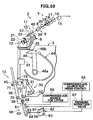
- the yarn joining cart 3 mainly includes, as shown in FIG. 2 , a splicer (a yarn joining device) 43, a suction pipe (a second catching member) 44, the suction mouth (a first catching member) 46, a package braking part 30, and a package reverse-rotating part 36.
- the yarn joining cart 3 can travel on a rail 41 that is fixed to the frame 6.
- the yarn joining cart 3 moves to that spinning unit 2 by traveling on the rail 41, stops there, and performs yarn joining.
- the suction mouth 46 catches a yarn end of the package 45 and guides it to the splicer 43.
- the suction mouth 46 is capable of pivoting vertically around a base end part 46a.
- a tapered suction part 46b (a tip end part) that extends in a pivoting direction of the suction mouth 46 is arranged on an opposite end part of the base end part 46a of the suction mouth 46.
- a width of the suction part 46b is about the same as a width of the package 45.
- a suction port 46c (see FIG. 6 ) for sucking air is arranged in one surface (an outer curved surface) of the suction part 46b that is located away from the base end part 46a.
- the suction pipe 44 catches a yarn end from the spinning device 9 and guides it to the splicer 43. More specifically, the suction pipe 44 is pivotable vertically around an axis and is capable of catching a yarn end (an upper yarn) fed from the spinning device 9 by suction and guiding it to the splicer 43.
- the splicer 43 joins the yarn end (the upper yarn) caught and guided thereto by the suction pipe 44 and the yarn end (the lower yarn) caught and guided thereto by the suction mouth 46. Although an explanation about the detailed configuration of the splicer 43 is omitted herefrom, the splicer 43 performs the operation of joining the upper yarn and the lower yarn by twisting the yarn ends thereof with a swirling air current.
- the package braking part 30 includes a plate driving arm 31 and a package plate (a package contacting part) 32.
- the package plate 32 extends from a tip end part of the plate driving arm 31 in a pivoting direction of the plate driving arm 31.
- the plate driving arm 31 is pivotable around a support shaft. By pivoting the plate driving arm 31, the package plate 32 can be moved so as to contact the package 45 or separate from the package 45.
- the package plate 32 is an arcuate plate and can contact a wide area of the package 45.
- a brake can be applied (stopped) to the rotation of the package 45 by pivoting the plate driving arm 31 around the support shaft and causing the package plate 32 to contact the package 45.
- the package reverse-rotating part 36 includes a reverse rotation arm 37 and a reverse rotation roller 38.
- the reverse rotation arm 37 is pivotable around a support shaft. By pivoting the reverse rotation arm 37, the reverse rotation roller 38 can be moved so as to contact the package 45 or separate from the package 45.
- the reverse rotation arm 37 includes a not-shown driving means.
- the reverse rotation roller 38 can be rotationally driven with this driving means in a direction that is opposite of the direction of rotation of the winding drum 72.
- the package 45 can be driven in the reverse direction (that is, can be rotationally driven in a direction that is opposite of the direction in which the package 45 is rotationally driven by the winding drum 72).
- suction mouth represents a position of the suction mouth 46
- package plate represents a position of the package plate 32
- lifter port represents a supply state of the compressed air to the lifter port 68
- contact-pressure port represents a supply state of the compressed air to the contact-pressure port 63
- back-pressure port represents a supply state of the compressed air to the back-pressure port 64.
- suction mouth “sucking position” represents a position of the suction mouth 46 at which a catching operation is performed
- retracted position represents a position at which the suction mouth 46 is retracted from the sucking position.
- package plate “separated position” represents a position at which the package plate 32 is separated from the package 45
- contact position represents a position at which the package plate 32 is in contact with the package 45.
- the package plate 32 is positioned at the separated position and no air is supplied to the back-pressure port 64 and the lifter port 68.
- the winding drum 72 contacts the package 45 at a predetermined contact pressure, whereby the spun yarn 10 is appropriately wound into the package 45.
- the yarn-defect detecting device 52 When the yarn-defect detecting device 52 detects a defect in the spun yarn 10 during winding of the spun yarn 10, the yarn-defect detecting device 52 transmits a yarn-defect detection signal to the unit controller 92. Upon receiving the yarn-defect detection signal, the unit controller 92 causes the cutter 57 to immediately cut the spun yarn 10, and stops the operation of the drafting device 7, the spinning device 9, and the like.
- the cut yarn end (the lower yarn) is wound into the rotating package 45 by the winding device 13. Because the defect detected by the yarn-defect detecting device 52 in the spun yarn 10 is present downstream of the cutter 57, a portion of the spun yarn 10 containing the defect is also once wound into the package 45.
- the unit controller 92 controls, after stopping the operation of the drafting device 7, the spinning device 9, and the like, the solenoid valve 91 to connect the lifter port 68 to the compressed-air source for lifter 69, thereby starting supply of compressed air to the lifter port 68 (see a time point A in FIG. 11 ).
- the piston rod 61 moves upward by a distance equal to only the stroke of the lifter piston 85, whereby the cradle arm 71 is driven leftward in FIG. 2 .
- the cradle arm 71 is driven so as to separate from the winding drum 72 by the lifter part 90 that is the driving mechanism.
- the package 45 is moved to a position that is separated by a small distance from the winding drum 72, whereby a rotational speed of the package 45 is reduced.
- the unit controller 92 transmits a control signal to the yarn joining cart 3 to cause the yarn joining cart 3 to travel to the position of the spinning unit 2 to perform the yarn joining.
- the unit controller 92 applies brake to the rotation of the package 45 by using the package plate 32 of the package braking part 30.
- the plate driving arm 31 is pivoted around the support shaft thereby causing the package plate 32 to be pressed against and contact the package 45.
- the rotation of the package 45 is stopped and the package 45 is held by the lifter part 90 at a position that is further away from the winding drum 72 than the position that is separated by the small distance from the winding drum 72.
- the package braking part 30 is returned to its original position (a position separated from the package 45). The package 45 is held at this position by the action of the lifter part 90 even if the package braking part 30 is returned to the position that is separated from the package 45.
- the unit controller 92 precisely controls, to ensure the catching operation of catching the yarn end (the lower yarn) of the package 45 with the suction mouth 46, a positional relation between the surface of the package 45 and the suction mouth 46.
- the yarn end cannot be caught surely if the surface of the package 45 and the suction mouth 46 are not positioned in an appropriate positional relation when catching the lower yarn with the suction mouth 46 by suction. It is preferable that the suction port 46c of the suction mouth 46 that sucks the yarn end is positioned exactly at a position that is separated by a predetermined distance from the surface of the package 45. If this distance is not accurate, the suction action with respect to the surface of the package 45 becomes unstable. However, there may be a dimension error in the winding device 13 and the like, moreover, the diameter of the yarn layer on the package 45 increases as the winding advances. Therefore, the surface of the package 45 cannot be positioned precisely only by separating the package 45 from the winding drum 72 with the package plate 32.
- the surface of the package 45 cannot be positioned accurately with the method of positioning the surface of the package 45 by pushing the package plate 32 between the package 45 and the winding drum 72.
- a success rate of catching the yarn end is improved by precisely positioning the surface of the package 45 to the predetermined position with respect to the suction mouth 46.
- the unit controller 92 causes the suction mouth 46 to pivot around the base end part 46a (in a counterclockwise direction in FIG. 5 ) from the retracted position and holds the suction mouth 46 in the sucking position (see a time point B in FIG. 11 ).
- the "sucking position" represents a position of the suction mouth 46 that is suitable for performing the catching operation of catching the yarn end of the package 45 with the suction mouth 46.
- the unit controller 92 controls the air cylinder 60 so as to drive the cradle arm 71 so that the package 45 moves in the approaching direction. Specifically, supply of the compressed air to the lifter port 68 is stopped (see a time point C in FIG. 11 ) while maintaining the state in which the compressed air is supplied to the contact-pressure port 63 and the back-pressure port 64.
- the lifter port 68 in the open state in this manner, because the lock by the wedge action is released in the lifter part 90, the piston rod 61 moves downward, whereby the cradle arm 71 pivots rightward from its pivoting position shown in FIG. 5 .
- the cradle arm 71 pivots in this manner, as shown in FIG.
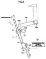
- the surface of the package 45 contacts the suction mouth 46 that is in the sucking position. Because the compressed air is being supplied to the back-pressure port 64, the momentum of the cradle arm 71 achieved by the pivoting is weakened, and an impact generated when the package 45 contacts the suction mouth 46 can be softened.
- the suction part 46b of the suction mouth 46 is tapered and extends in the pivoting direction.
- the package 45 contacts the surface of the suction part 46b that is away from the base end part 46a.
- the suction port 46c is formed in this surface of the suction part 46b that is away from the base end part 46a.
- the suction port 46c contacts a surface of the package 45 (in other words, at least a part of the suction port 46c is closed by the surface of the package 45).
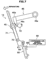
- the unit controller 92 controls the air cylinder 60 so as to drive the cradle arm 71 so that the package 45 moves in the separating direction. Specifically, the air cylinder 60 is controlled to again supply the compressed air to the lifter port 68 (see a time point D in FIG. 11 ). With this action, the piston rod 61 is locked to the tapering member 86 by the above-mentioned wedge action, and the piston rod 61, the tapering member 86, and the lifter piston 85 integrally move upward in FIG. 4 .
- the position of the piston rod 61 in the air cylinder 60 in the state shown in FIG. 6 may vary depending on the diameter of the package 45, the hardness of the package 45, a dimension error in the winding device 13 of each spinning unit 2, and the like.
- the movement amount is always constant. Accordingly, the cradle arm 71 pivots by only a predetermined pivoting amount leftward from its pivoting position shown in FIG. 6 .
- the package 45 that is supported by the cradle arm 71 moves by only a predetermined distance in the separating direction from its state shown in FIG. 6 in which the surface of the package 45 is in contact with the suction part 46b (i.e., the suction port 46c) of the suction mouth 46, and the state of the package 45 changes to a separated state shown in FIG. 7 in which the package 45 is separated from the suction mouth 46.
- the suction part 46b i.e., the suction port 46c
- the unit controller 92 provides a control to start the yarn joining.
- the unit controller 92 operates the drafting device 7, the spinning device 9, and the like again and restarts formation of the spun yarn 10.
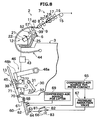
- the unit controller 92 causes the suction pipe 44 to pivot to a position near the downstream of the spinning device 9 as shown in FIG. 8 , causes the suction pipe 44 to generate a suction air current, and provides a control to catch the yarn end (the upper yarn) fed from the spinning device 9.
- the suction pipe 44 is pivoted downward while continuing the suction thereby pulling the spun yarn 10 from the spinning device 9 therewith and guiding it to the splicer 43.
- the unit controller 92 causes the suction port 46c of the suction mouth 46, which is at the sucking position, to generate a suction air current.
- the reverse rotation arm 37 is pivoted to cause the reverse rotation roller 38 to contact the package 45 whereby the package 45 starts rotating in the reverse direction.
- the yarn end on the surface of the package 45 can be sucked favorably through the suction port 46c that is formed in the surface (the surface where the surface of the package 45 was in contact) of the suction part 46b that is away from the base end part 46a.
- the yarn end (the lower yarn) is pulled from the outer peripheral surface of the reverse-rotating package 45, and the pulled yarn end is sucked and caught by the suction port 46c of the suction mouth 46.
- the spun yarn 10 including the defect can be removed from the package 45 when the spun yarn 10 including the defect is pulled from the package 45 and sucked with the suction mouth 46.
- the catching operation including sucking and catching the yarn end of the package 45 with the suction mouth 46 is performed after a positional relation (distance) between the surface of the package 45 and the suction mouth 46 is adjusted based on the state in which the surface of the package 45 and the suction mouth 46 were in contact with each other. As a result, even if the catching operation is performed repeatedly, each time the surface of the package 45 is positioned at the same position with respect to the suction mouth 46 (the suction port 46c) and the yarn end can be caught stably.
- the suction mouth 46 that has sucked the lower yarn is pivoted upward so as to move to a yarn-joining guiding position, and then, the lower yarn is guided to the splicer 43.
- the reverse rotation of the package 45 is stopped after the lower yarn is guided to the splicer 43.
- the splicer 43 joins the upper yarn and the lower yarn that are guided thereto.
- the spinning by the spinning device 9 is continued even while the yarn joining is being performed.
- the winding operation by the winding device 13 is stopped while the yarn joining is being performed, because the spun yarn 10 is continually fed from the spinning device 9 during this period, a slack of the spun yarn 10 occurs if no measure is taken.
- the slack of the spun yarn 10 is prevented by winding the spun yarn 10 on the slack removing roller 21.
- the spinning frame 1 includes the suction mouth 46, the cradle arm 71, the air cylinder 60, and the unit controller 92.
- the suction mouth 46 performs a catching operation of catching the yarn end of the package 45.
- the cradle arm 71 rotatably supports the package 45.
- the cradle arm 71 movably supports the package 45 so that the package 45 is movable in both of the approaching direction in which the package 45 moves toward the suction mouth 46 and the separating direction in which the package 45 moves away from the suction mouth 46.
- the air cylinder 60 drives the cradle arm 71 to move the package 45 in both of the approaching direction and the separating direction.
- the unit controller 92 controls, after causing the suction mouth 46 to contact the surface of the package 45, the air cylinder 60 (the lifter part 90) to move the package 45 in the separating direction.
- the unit controller 92 provides a control so that the suction mouth 46 performs the catching operation in the state in which the surface of the package 45 and the suction mouth 46 are separated from each other.
- the unit controller 92 controls the air cylinder 60 (the lifter part 90) so that the package 45 is moved in the separating direction by only a predetermined distance from the state in which the surface of the package 45 is in contact with the suction mouth 46.
- the spinning frame 1 further includes the winding drum 72 that rotationally drives the package 45 while being in contact with the package 45.
- the unit controller 92 controls the air cylinder 60, after separating the package 45 from the winding drum 72, so that the surface of the package 45 contacts the suction mouth 46.
- the spinning frame 1 further includes the package reverse-rotating part 36 that rotationally drives the package 45 in the direction opposite to the direction in which the package 45 is rotationally driven by the winding drum 72 by contacting the package 45 that has been separated from the winding drum 72. Accordingly, the catching operation performed by the suction mouth 46 in the state in which the package 45 is separated from the winding drum 72 can be performed suitably.
- the spinning frame 1 further includes the package plate 32 that brakes the rotation of the package 45 by being in contact with the package 45.
- the package plate 32 contacts the package 45 in a period from a time point at which the package 45 is separated from the winding drum 72 to a time point at which the package 45 contacts the suction mouth 46.
- the cradle arm 71 is driven by the air cylinder 60 (the lifter part 90) in both of the approaching direction and the separating direction.
- the motion of the cradle arm 71 that is driven by the air cylinder 60 including the lifter part 90 is softened by a spring action of the air, the impact generated when the package 45 contacts the suction mouth 46 is softened, and the possibility of occurrence of variations in the position based on which the positioning is performed is reduced. Moreover, the suction mouth 46 can be prevented from being broken due to the impact at the time of contact with the package 45.
- the unit controller 92 controls the air cylinder 60 (the lifter part 90) to reduce the winding speed of the package 45 by causing the package 45 to move away from the winding drum 72.
- the configuration of the spinning frame 1 can be made simple as no special mechanism is required to adjust the position of the package 45.
- the spinning frame 1 is configured as explained below.
- the suction mouth 46 includes the base end part 46a as the pivoting center and the suction part 46b having a shape that extends in the pivoting direction.
- the suction port 46c for catching the yarn end by suction is arranged on one surface of the suction part 46b that is away from the base end part 46a. When catching the yarn end with the suction port 46c, the distance from the base end part 46a to the package 45 is longer than the distance from the base end part 46a to the suction port 46c.
- the surface of the package 45 and the suction port 46c of the suction mouth 46 are arranged facing each other whereby the catching of the yarn end by the suction action can be surely performed.
- the unit controller 92 controls the air cylinder 60 (the lifter part 90) so that the surface of the package 45 contacts the surface of the suction part 46b of the suction mouth 46 in which the suction port 46c has been formed.
- the spinning frame 1 further includes a plurality of spinning units 2 and the yarn joining cart 3.
- Each spinning unit 2 includes the cradle arm 71 and the air cylinder 60.
- the yarn joining cart 3 is capable of traveling (moving) with respect to each of the plurality of spinning units 2 and performing the catching operation in each spinning unit 2.
- the suction mouth 46 is arranged in the yarn joining cart 3.
- the spinning frame 1 includes the spinning device 9, the suction pipe 44, and the splicer 43.
- the suction pipe 44 catches and guides the yarn end from the spinning device 9.
- the splicer 43 joins the yarn end caught by the suction mouth 46 and the yarn end caught by the suction pipe 44.
- the package 45 and the suction mouth 46 are caused to contact each other by pivoting both the package 45 and the suction mouth 46.
- the present invention is not limited to this configuration.
- the suction mouth 46 and the package 45 can be caused to contact each other by pivoting only the suction mouth 46, and then the lifter part 90 can be driven to move the package 45.
- the movement of the cradle arm 71 is controlled so that the suction port 46c and the surface of the package 45 are separated from each other by the predetermined distance.
- a sensor e.g., a potentiometer
- This sensor can be used to control the movement of the cradle arm 71 so that the suction port 46c and the surface of the package 45 are separated from each other by the predetermined distance based on an inclination detected by this sensor in the state in which the surface of the package 45 and the suction mouth 46 were in contact with each other.
- the cradle arm 71 can be driven by a fluid-pressure cylinder (e.g., an oil-pressure cylinder) instead of the air cylinder 60.
- a fluid-pressure cylinder e.g., an oil-pressure cylinder
- the cradle arm 71 can be driven by any other actuator (e.g., an electric motor).
- the package braking part 30 (the package plate 32) can be omitted.
- the spinning device 9 is arranged above the cradle arm 71 (the winding device 13), and the spun yarn 10 travels downward in the spinning unit 2.
- a configuration of a textile machine to which the present invention is applied is not limited to this configuration.
- the present invention can similarly be applied to a textile machine in which the yarn supplying section that supplies the yarn is arranged below the cradle arm (the winding device) and the yarn travels upward.
- the yarn supplying section is a structural component that supplies the yarn to the package and can include a yarn supplying bobbin on which the yarn has been wound, and the like.
- the suction mouth 46 is arranged in the yarn joining cart 3.
- a configuration of a textile machine to which the present invention is applied is not limited to this configuration. That is, the suction mouth 46 can be arranged in each spinning unit 2.
- the present invention is applied to the spinning frame (an air spinning frame) 1.
- the present invention can similarly be applied to other textile machines such as an open-end spinning frame and an automatic winder.
- the splicer is used as the yarn joining device; however, the present invention is not limited to this configuration. That is, in an alternative configuration, for example, a knotter and the like can be used as the yarn joining device.
- the spun yarn 10 is fed from the spinning device 9 to the yarn feeding device 11.
- a configuration of a textile machine according to the present invention is not limited to this configuration.
- the yarn feeding device 11 can be omitted (that is, the yarn feeding device 11 is not provided), and the spun yarn 10 can be pulled from the spinning device 9 by using the slack removing roller 21.
- the spun yarn 10 is cut by the cutter 57 upon detection of the yarn defect.
- a configuration of a textile machine according to the present invention is not limited to this configuration.
- the cutter 57 can be omitted (that is, the cutter 57 is not provided), and the spun yarn 10 can be cut by stopping the spinning operation by the spinning device 9.
- a work cart is used as the yarn joining cart 3; however, it is sufficient that the work cart includes the first catching member. Moreover, the work cart can be caused to move with respect to a limited number of the winding units, e.g., two winding units.
- the supply of the compressed air to the back-pressure port 64 is started at a timing at which the package plate 32 is caused to contact the package 45; however, the supply of the compressed air to the back-pressure port 64 can be started at a timing that is little before the time point at which the package 45 is caused to contact the winding drum 72 (a timing little before the time point E in FIG. 11 ).
- the winding drum 72 of each spinning unit is connected to a not-shown electric motor via a driving shaft that is shared by a large number of the spinning units.
- a separate driving means dedicated to one spinning unit can be arranged in each spinning unit and the winding drum 72 of each spinning unit can be driven with this driving means.
- the surface of the package 45 and the suction mouth 46 are caused to contact after separating the package 45 from the winding drum 72.
- the surface of the package 45 and the suction mouth 46 can be caused to contact without separating the package 45 from the winding drum 72.
- the winding drum 72 in each spinning unit is configured so as to rotate freely and separately, or a separate driving means is arranged in each spinning unit.
- the unit controller (the controlling section) 92 controls the air cylinder (the driving mechanism) 60 so that the suction mouth (the first catching member) 46 performs the catching operation in the state in which the surface of the package 45 and the winding drum 72 are separated.
- a textile machine includes a first catching member, a cradle arm, a driving mechanism, and a controlling section.
- the first catching member performs a catching operation of catching a yarn end of a package.
- the cradle arm rotatably supports the package and also movably supports the package so that the package is movable in a separating direction in which the package moves away from the first catching member.
- the driving mechanism drives the cradle arm to move the package in the separating direction.
- the controlling section controls the driving mechanism to move the package in the separating direction after causing a surface of the package and the first catching member to contact each other, and provides a control so that the first catching member performs the catching operation in the state in which the surface of the package and the first catching member are separated from each other.
- the controlling section controls the driving mechanism so that the package is moved in the separating direction by only a predetermined distance from the state in which the surface of the package is in contact with the first catching member.
- the above textile machine further includes a winding drum that contacts the package and rotates while being in contact with the package and the package is movable by driving the cradle arm with the driving mechanism to a position at which the package is separated from the winding drum, and the controlling section controls the driving mechanism so that the first catching member performs the catching operation in the state in which the surface of the package and the winding drum are separated from each other.
- the winding drum rotationally drives the package
- the controlling section controls the driving mechanism so that the surface of the package and the first catching member are caused to contact each other after the package is separated from the winding drum.
- the above textile machine further includes a package reverse-rotating part that rotationally drives the package in a direction opposite to the direction in which the package is rotationally driven by the winding drum by contacting the package that has been separated from the winding drum.
- the above textile machine further includes a package contacting part capable of applying brake to rotation of the package by contacting the package, and the package contacting part contacts the package in a period from a time point at which the package is separated from the winding drum to a time point at which the package contacts the first catching member.
- the driving mechanism is an air cylinder.
- the motion of the cradle arm that is driven by the driving mechanism is softened by a spring action of the air, the impact generated when the package contacts the first catching member is softened, and the possibility of occurrence of variations in the position based on which the positioning is performed is reduced.
- the first catching member includes a base end part as a pivoting center and a tip end part formed in a shape that extends in a pivoting direction.
- a suction port is formed in a surface of the tip end part that is away from the base end part.
- the suction port of the first catching member and the surface of the package are arranged facing each other whereby the catching of the yarn end by the suction action can be surely performed.
- controlling section controls the driving mechanism, to reduce a winding speed of the package, so as to move the package away from the winding drum.
- controlling section controls the driving mechanism so that the surface of the package contacts the surface in which the suction port is formed.
- the above textile machine further includes a plurality of winding units and a work cart.
- the plurality of winding units each includes the cradle arm and the driving mechanism.
- the work cart is capable of moving with respect to each winding unit and performing the catching operation in each winding unit.
- the first catching member is arranged in the work cart.
- the above textile machine further includes a yarn supplying section, a second catching member, and a yarn joining device.
- the yarn supplying section supplies a yarn to the package.
- the second catching member catches and guides a yarn end from the yarn supplying section.
- the yarn joining device joins the yarn end caught by the first catching member to the yarn end caught by the second catching member.
Landscapes
- Engineering & Computer Science (AREA)
- Textile Engineering (AREA)
- Mechanical Engineering (AREA)
- Quality & Reliability (AREA)
- Replacing, Conveying, And Pick-Finding For Filamentary Materials (AREA)
- Spinning Or Twisting Of Yarns (AREA)
Applications Claiming Priority (1)
| Application Number | Priority Date | Filing Date | Title |
|---|---|---|---|
| JP2015083893A JP2016204062A (ja) | 2015-04-16 | 2015-04-16 | 繊維機械 |
Publications (2)
| Publication Number | Publication Date |
|---|---|
| EP3081518A1 true EP3081518A1 (de) | 2016-10-19 |
| EP3081518B1 EP3081518B1 (de) | 2018-06-06 |
Family
ID=55745572
Family Applications (1)
| Application Number | Title | Priority Date | Filing Date |
|---|---|---|---|
| EP16164026.3A Not-in-force EP3081518B1 (de) | 2015-04-16 | 2016-04-06 | Textilmaschine |
Country Status (3)
| Country | Link |
|---|---|
| EP (1) | EP3081518B1 (de) |
| JP (1) | JP2016204062A (de) |
| CN (1) | CN106048797B (de) |
Cited By (1)
| Publication number | Priority date | Publication date | Assignee | Title |
|---|---|---|---|---|
| EP3453662A1 (de) * | 2017-09-04 | 2019-03-13 | Murata Machinery, Ltd. | Garnwicklungsmaschine |
Families Citing this family (3)
| Publication number | Priority date | Publication date | Assignee | Title |
|---|---|---|---|---|
| CN112125064A (zh) * | 2020-09-28 | 2020-12-25 | 安徽日发纺织机械有限公司 | 一种气动捻接装置及其捻接方法 |
| CN112125063A (zh) * | 2020-09-28 | 2020-12-25 | 安徽日发纺织机械有限公司 | 一种带有单锭吸纱嘴的气动捻接装置及其捻接方法 |
| CN118811606B (zh) * | 2024-09-14 | 2025-03-07 | 浙江万利碳纤维智能装备有限公司 | 一种碳纤维收丝机上使用的背压调整控制机构 |
Citations (3)
| Publication number | Priority date | Publication date | Assignee | Title |
|---|---|---|---|---|
| JP2010189083A (ja) | 2009-02-16 | 2010-09-02 | Murata Machinery Ltd | 繊維機械 |
| JP2011037608A (ja) * | 2009-08-17 | 2011-02-24 | Murata Machinery Ltd | 繊維機械 |
| EP2738129A2 (de) * | 2012-11-30 | 2014-06-04 | Murata Machinery, Ltd. | Garnwickelmaschine und Textilmaschine mit der Garnwickelmaschine |
Family Cites Families (8)
| Publication number | Priority date | Publication date | Assignee | Title |
|---|---|---|---|---|
| US3652025A (en) * | 1970-02-02 | 1972-03-28 | Leesona Corp | Bobbin processing |
| DE60120082T9 (de) * | 2000-11-16 | 2012-04-26 | Murata Kikai K.K. | Spinnvorrichtung |
| JP4048902B2 (ja) * | 2002-10-07 | 2008-02-20 | 村田機械株式会社 | 紡績機の糸弛み取り装置 |
| JP2006225092A (ja) * | 2005-02-16 | 2006-08-31 | Murata Mach Ltd | 自動玉揚げ動作方法 |
| ITMI20060008A1 (it) * | 2006-01-04 | 2007-07-05 | Savio Macchine Tessili Spa | Dispositivo posizionatore del bandolo del filo per carrelli di servizio a filatoi open-end |
| JP5471924B2 (ja) * | 2010-07-15 | 2014-04-16 | 村田機械株式会社 | 糸巻取装置 |
| JP2013063809A (ja) * | 2011-09-15 | 2013-04-11 | Murata Machinery Ltd | 糸巻取ユニット及び糸巻取機 |
| JP2013067474A (ja) * | 2011-09-21 | 2013-04-18 | Murata Machinery Ltd | 糸巻取機及び糸巻取ユニット |
-
2015
- 2015-04-16 JP JP2015083893A patent/JP2016204062A/ja active Pending
-
2016
- 2016-04-06 EP EP16164026.3A patent/EP3081518B1/de not_active Not-in-force
- 2016-04-06 CN CN201610208261.1A patent/CN106048797B/zh active Active
Patent Citations (3)
| Publication number | Priority date | Publication date | Assignee | Title |
|---|---|---|---|---|
| JP2010189083A (ja) | 2009-02-16 | 2010-09-02 | Murata Machinery Ltd | 繊維機械 |
| JP2011037608A (ja) * | 2009-08-17 | 2011-02-24 | Murata Machinery Ltd | 繊維機械 |
| EP2738129A2 (de) * | 2012-11-30 | 2014-06-04 | Murata Machinery, Ltd. | Garnwickelmaschine und Textilmaschine mit der Garnwickelmaschine |
Cited By (1)
| Publication number | Priority date | Publication date | Assignee | Title |
|---|---|---|---|---|
| EP3453662A1 (de) * | 2017-09-04 | 2019-03-13 | Murata Machinery, Ltd. | Garnwicklungsmaschine |
Also Published As
| Publication number | Publication date |
|---|---|
| JP2016204062A (ja) | 2016-12-08 |
| CN106048797A (zh) | 2016-10-26 |
| CN106048797B (zh) | 2020-05-19 |
| EP3081518B1 (de) | 2018-06-06 |
Similar Documents
| Publication | Publication Date | Title |
|---|---|---|
| JP4048902B2 (ja) | 紡績機の糸弛み取り装置 | |
| CN110158207B (zh) | 空气纺纱机和空气纺纱方法 | |
| CN102730482A (zh) | 纱线卷绕机及纱线引出方法 | |
| CN102602745A (zh) | 纱线卷取机 | |
| EP3081518B1 (de) | Textilmaschine | |
| EP3072840B1 (de) | Garnwickelmaschine und garnwickelverfahren | |
| EP2366651B1 (de) | Garnwicklungsvorrichtung | |
| CN103848287A (zh) | 纱线卷取机以及具备纱线卷取机的纤维机械 | |
| JP2009286608A (ja) | 自動ワインダ | |
| EP2749517A1 (de) | Spinnmaschine | |
| CN105253703B (zh) | 纱线卷取机以及纱线卷取方法 | |
| EP1457446A2 (de) | Vorrichtung zur Fadenspannungsregelung und zur Beseitigung von Fadenlockerungen in einer Garnwickeleinrichtung | |
| EP3025996B1 (de) | Garnwickelmaschine mit einer garnverbindungsvorrichtung, und garnverbindungsverfahren | |
| JP2017089091A (ja) | エアジェット紡績機上の紡績工程の再開の方法、及びその方法を実施するためのエアジェット紡績機 | |
| JP2010189083A (ja) | 繊維機械 | |
| CN106149110A (zh) | 在气流纺纱机的工作站处大量纺纱进入的方法及用于执行该方法的装置 | |
| JP2014040316A (ja) | 糸巻取ユニット及び糸巻取機 | |
| JP2013154991A (ja) | 糸巻取機及び糸巻取方法 | |
| CN101346297B (zh) | 用于在生产交叉卷绕筒子的纺织机上卷绕纱线的方法及生产交叉卷绕筒子的纺织机 | |
| JP2004277944A (ja) | 紡績機 | |
| EP2853510B1 (de) | Versorgungsfahrzeug einer Textilmaschine | |
| JP7553257B2 (ja) | 繊維機械の作業ユニットにおいて糸継ぎ結合部を形成するための方法ならびに繊維機械の作業ユニット | |
| JP2014218315A (ja) | 糸巻取機 | |
| CN211171024U (zh) | 一种纱线的纺纱机构 | |
| CN110699796B (zh) | 一种纱线的纺纱机构 |
Legal Events
| Date | Code | Title | Description |
|---|---|---|---|
| PUAI | Public reference made under article 153(3) epc to a published international application that has entered the european phase |
Free format text: ORIGINAL CODE: 0009012 |
|
| AK | Designated contracting states |
Kind code of ref document: A1 Designated state(s): AL AT BE BG CH CY CZ DE DK EE ES FI FR GB GR HR HU IE IS IT LI LT LU LV MC MK MT NL NO PL PT RO RS SE SI SK SM TR |
|
| AX | Request for extension of the european patent |
Extension state: BA ME |
|
| STAA | Information on the status of an ep patent application or granted ep patent |
Free format text: STATUS: REQUEST FOR EXAMINATION WAS MADE |
|
| 17P | Request for examination filed |
Effective date: 20170407 |
|
| RBV | Designated contracting states (corrected) |
Designated state(s): AL AT BE BG CH CY CZ DE DK EE ES FI FR GB GR HR HU IE IS IT LI LT LU LV MC MK MT NL NO PL PT RO RS SE SI SK SM TR |
|
| RIC1 | Information provided on ipc code assigned before grant |
Ipc: B65H 63/036 20060101AFI20171211BHEP Ipc: B65H 67/08 20060101ALI20171211BHEP |
|
| GRAP | Despatch of communication of intention to grant a patent |
Free format text: ORIGINAL CODE: EPIDOSNIGR1 |
|
| STAA | Information on the status of an ep patent application or granted ep patent |
Free format text: STATUS: GRANT OF PATENT IS INTENDED |
|
| INTG | Intention to grant announced |
Effective date: 20180124 |
|
| GRAS | Grant fee paid |
Free format text: ORIGINAL CODE: EPIDOSNIGR3 |
|
| GRAA | (expected) grant |
Free format text: ORIGINAL CODE: 0009210 |
|
| STAA | Information on the status of an ep patent application or granted ep patent |
Free format text: STATUS: THE PATENT HAS BEEN GRANTED |
|
| AK | Designated contracting states |
Kind code of ref document: B1 Designated state(s): AL AT BE BG CH CY CZ DE DK EE ES FI FR GB GR HR HU IE IS IT LI LT LU LV MC MK MT NL NO PL PT RO RS SE SI SK SM TR |
|
| REG | Reference to a national code |
Ref country code: GB Ref legal event code: FG4D |
|
| REG | Reference to a national code |
Ref country code: CH Ref legal event code: EP Ref country code: AT Ref legal event code: REF Ref document number: 1005864 Country of ref document: AT Kind code of ref document: T Effective date: 20180615 |
|
| REG | Reference to a national code |
Ref country code: IE Ref legal event code: FG4D |
|
| REG | Reference to a national code |
Ref country code: DE Ref legal event code: R096 Ref document number: 602016003274 Country of ref document: DE |
|
| REG | Reference to a national code |
Ref country code: NL Ref legal event code: MP Effective date: 20180606 |
|
| REG | Reference to a national code |
Ref country code: LT Ref legal event code: MG4D |
|
| PG25 | Lapsed in a contracting state [announced via postgrant information from national office to epo] |
Ref country code: BG Free format text: LAPSE BECAUSE OF FAILURE TO SUBMIT A TRANSLATION OF THE DESCRIPTION OR TO PAY THE FEE WITHIN THE PRESCRIBED TIME-LIMIT Effective date: 20180906 Ref country code: NO Free format text: LAPSE BECAUSE OF FAILURE TO SUBMIT A TRANSLATION OF THE DESCRIPTION OR TO PAY THE FEE WITHIN THE PRESCRIBED TIME-LIMIT Effective date: 20180906 Ref country code: FI Free format text: LAPSE BECAUSE OF FAILURE TO SUBMIT A TRANSLATION OF THE DESCRIPTION OR TO PAY THE FEE WITHIN THE PRESCRIBED TIME-LIMIT Effective date: 20180606 Ref country code: SE Free format text: LAPSE BECAUSE OF FAILURE TO SUBMIT A TRANSLATION OF THE DESCRIPTION OR TO PAY THE FEE WITHIN THE PRESCRIBED TIME-LIMIT Effective date: 20180606 Ref country code: CY Free format text: LAPSE BECAUSE OF FAILURE TO SUBMIT A TRANSLATION OF THE DESCRIPTION OR TO PAY THE FEE WITHIN THE PRESCRIBED TIME-LIMIT Effective date: 20180606 Ref country code: LT Free format text: LAPSE BECAUSE OF FAILURE TO SUBMIT A TRANSLATION OF THE DESCRIPTION OR TO PAY THE FEE WITHIN THE PRESCRIBED TIME-LIMIT Effective date: 20180606 Ref country code: ES Free format text: LAPSE BECAUSE OF FAILURE TO SUBMIT A TRANSLATION OF THE DESCRIPTION OR TO PAY THE FEE WITHIN THE PRESCRIBED TIME-LIMIT Effective date: 20180606 |
|
| PG25 | Lapsed in a contracting state [announced via postgrant information from national office to epo] |
Ref country code: HR Free format text: LAPSE BECAUSE OF FAILURE TO SUBMIT A TRANSLATION OF THE DESCRIPTION OR TO PAY THE FEE WITHIN THE PRESCRIBED TIME-LIMIT Effective date: 20180606 Ref country code: RS Free format text: LAPSE BECAUSE OF FAILURE TO SUBMIT A TRANSLATION OF THE DESCRIPTION OR TO PAY THE FEE WITHIN THE PRESCRIBED TIME-LIMIT Effective date: 20180606 Ref country code: GR Free format text: LAPSE BECAUSE OF FAILURE TO SUBMIT A TRANSLATION OF THE DESCRIPTION OR TO PAY THE FEE WITHIN THE PRESCRIBED TIME-LIMIT Effective date: 20180907 Ref country code: LV Free format text: LAPSE BECAUSE OF FAILURE TO SUBMIT A TRANSLATION OF THE DESCRIPTION OR TO PAY THE FEE WITHIN THE PRESCRIBED TIME-LIMIT Effective date: 20180606 |
|
| REG | Reference to a national code |
Ref country code: AT Ref legal event code: MK05 Ref document number: 1005864 Country of ref document: AT Kind code of ref document: T Effective date: 20180606 |
|
| PG25 | Lapsed in a contracting state [announced via postgrant information from national office to epo] |
Ref country code: NL Free format text: LAPSE BECAUSE OF FAILURE TO SUBMIT A TRANSLATION OF THE DESCRIPTION OR TO PAY THE FEE WITHIN THE PRESCRIBED TIME-LIMIT Effective date: 20180606 |
|
| PG25 | Lapsed in a contracting state [announced via postgrant information from national office to epo] |
Ref country code: SK Free format text: LAPSE BECAUSE OF FAILURE TO SUBMIT A TRANSLATION OF THE DESCRIPTION OR TO PAY THE FEE WITHIN THE PRESCRIBED TIME-LIMIT Effective date: 20180606 Ref country code: RO Free format text: LAPSE BECAUSE OF FAILURE TO SUBMIT A TRANSLATION OF THE DESCRIPTION OR TO PAY THE FEE WITHIN THE PRESCRIBED TIME-LIMIT Effective date: 20180606 Ref country code: IS Free format text: LAPSE BECAUSE OF FAILURE TO SUBMIT A TRANSLATION OF THE DESCRIPTION OR TO PAY THE FEE WITHIN THE PRESCRIBED TIME-LIMIT Effective date: 20181006 Ref country code: EE Free format text: LAPSE BECAUSE OF FAILURE TO SUBMIT A TRANSLATION OF THE DESCRIPTION OR TO PAY THE FEE WITHIN THE PRESCRIBED TIME-LIMIT Effective date: 20180606 Ref country code: AT Free format text: LAPSE BECAUSE OF FAILURE TO SUBMIT A TRANSLATION OF THE DESCRIPTION OR TO PAY THE FEE WITHIN THE PRESCRIBED TIME-LIMIT Effective date: 20180606 Ref country code: PL Free format text: LAPSE BECAUSE OF FAILURE TO SUBMIT A TRANSLATION OF THE DESCRIPTION OR TO PAY THE FEE WITHIN THE PRESCRIBED TIME-LIMIT Effective date: 20180606 |
|
| PG25 | Lapsed in a contracting state [announced via postgrant information from national office to epo] |
Ref country code: SM Free format text: LAPSE BECAUSE OF FAILURE TO SUBMIT A TRANSLATION OF THE DESCRIPTION OR TO PAY THE FEE WITHIN THE PRESCRIBED TIME-LIMIT Effective date: 20180606 Ref country code: IT Free format text: LAPSE BECAUSE OF FAILURE TO SUBMIT A TRANSLATION OF THE DESCRIPTION OR TO PAY THE FEE WITHIN THE PRESCRIBED TIME-LIMIT Effective date: 20180606 |
|
| REG | Reference to a national code |
Ref country code: DE Ref legal event code: R097 Ref document number: 602016003274 Country of ref document: DE |
|
| PLBE | No opposition filed within time limit |
Free format text: ORIGINAL CODE: 0009261 |
|
| STAA | Information on the status of an ep patent application or granted ep patent |
Free format text: STATUS: NO OPPOSITION FILED WITHIN TIME LIMIT |
|
| 26N | No opposition filed |
Effective date: 20190307 |
|
| PG25 | Lapsed in a contracting state [announced via postgrant information from national office to epo] |
Ref country code: DK Free format text: LAPSE BECAUSE OF FAILURE TO SUBMIT A TRANSLATION OF THE DESCRIPTION OR TO PAY THE FEE WITHIN THE PRESCRIBED TIME-LIMIT Effective date: 20180606 Ref country code: SI Free format text: LAPSE BECAUSE OF FAILURE TO SUBMIT A TRANSLATION OF THE DESCRIPTION OR TO PAY THE FEE WITHIN THE PRESCRIBED TIME-LIMIT Effective date: 20180606 |
|
| PG25 | Lapsed in a contracting state [announced via postgrant information from national office to epo] |
Ref country code: AL Free format text: LAPSE BECAUSE OF FAILURE TO SUBMIT A TRANSLATION OF THE DESCRIPTION OR TO PAY THE FEE WITHIN THE PRESCRIBED TIME-LIMIT Effective date: 20180606 |
|
| REG | Reference to a national code |
Ref country code: BE Ref legal event code: MM Effective date: 20190430 |
|
| PG25 | Lapsed in a contracting state [announced via postgrant information from national office to epo] |
Ref country code: LU Free format text: LAPSE BECAUSE OF NON-PAYMENT OF DUE FEES Effective date: 20190406 Ref country code: MC Free format text: LAPSE BECAUSE OF FAILURE TO SUBMIT A TRANSLATION OF THE DESCRIPTION OR TO PAY THE FEE WITHIN THE PRESCRIBED TIME-LIMIT Effective date: 20180606 |
|
| PG25 | Lapsed in a contracting state [announced via postgrant information from national office to epo] |
Ref country code: BE Free format text: LAPSE BECAUSE OF NON-PAYMENT OF DUE FEES Effective date: 20190430 Ref country code: FR Free format text: LAPSE BECAUSE OF NON-PAYMENT OF DUE FEES Effective date: 20190430 |
|
| PG25 | Lapsed in a contracting state [announced via postgrant information from national office to epo] |
Ref country code: TR Free format text: LAPSE BECAUSE OF FAILURE TO SUBMIT A TRANSLATION OF THE DESCRIPTION OR TO PAY THE FEE WITHIN THE PRESCRIBED TIME-LIMIT Effective date: 20180606 |
|
| PG25 | Lapsed in a contracting state [announced via postgrant information from national office to epo] |
Ref country code: IE Free format text: LAPSE BECAUSE OF NON-PAYMENT OF DUE FEES Effective date: 20190406 |
|
| PG25 | Lapsed in a contracting state [announced via postgrant information from national office to epo] |
Ref country code: PT Free format text: LAPSE BECAUSE OF FAILURE TO SUBMIT A TRANSLATION OF THE DESCRIPTION OR TO PAY THE FEE WITHIN THE PRESCRIBED TIME-LIMIT Effective date: 20181008 |
|
| PGFP | Annual fee paid to national office [announced via postgrant information from national office to epo] |
Ref country code: CZ Payment date: 20200403 Year of fee payment: 5 Ref country code: DE Payment date: 20200420 Year of fee payment: 5 Ref country code: CH Payment date: 20200420 Year of fee payment: 5 |
|
| GBPC | Gb: european patent ceased through non-payment of renewal fee |
Effective date: 20200406 |
|
| PG25 | Lapsed in a contracting state [announced via postgrant information from national office to epo] |
Ref country code: GB Free format text: LAPSE BECAUSE OF NON-PAYMENT OF DUE FEES Effective date: 20200406 |
|
| PG25 | Lapsed in a contracting state [announced via postgrant information from national office to epo] |
Ref country code: MT Free format text: LAPSE BECAUSE OF FAILURE TO SUBMIT A TRANSLATION OF THE DESCRIPTION OR TO PAY THE FEE WITHIN THE PRESCRIBED TIME-LIMIT Effective date: 20180606 Ref country code: HU Free format text: LAPSE BECAUSE OF FAILURE TO SUBMIT A TRANSLATION OF THE DESCRIPTION OR TO PAY THE FEE WITHIN THE PRESCRIBED TIME-LIMIT; INVALID AB INITIO Effective date: 20160406 |
|
| REG | Reference to a national code |
Ref country code: DE Ref legal event code: R119 Ref document number: 602016003274 Country of ref document: DE |
|
| PG25 | Lapsed in a contracting state [announced via postgrant information from national office to epo] |
Ref country code: CZ Free format text: LAPSE BECAUSE OF NON-PAYMENT OF DUE FEES Effective date: 20210406 Ref country code: DE Free format text: LAPSE BECAUSE OF NON-PAYMENT OF DUE FEES Effective date: 20211103 Ref country code: CH Free format text: LAPSE BECAUSE OF NON-PAYMENT OF DUE FEES Effective date: 20210430 Ref country code: LI Free format text: LAPSE BECAUSE OF NON-PAYMENT OF DUE FEES Effective date: 20210430 |
|
| PG25 | Lapsed in a contracting state [announced via postgrant information from national office to epo] |
Ref country code: MK Free format text: LAPSE BECAUSE OF FAILURE TO SUBMIT A TRANSLATION OF THE DESCRIPTION OR TO PAY THE FEE WITHIN THE PRESCRIBED TIME-LIMIT Effective date: 20180606 |