EP3081343A1 - Plate partitioning facility and method for partitioning plate-shaped workpieces - Google Patents
Plate partitioning facility and method for partitioning plate-shaped workpieces Download PDFInfo
- Publication number
- EP3081343A1 EP3081343A1 EP16165015.5A EP16165015A EP3081343A1 EP 3081343 A1 EP3081343 A1 EP 3081343A1 EP 16165015 A EP16165015 A EP 16165015A EP 3081343 A1 EP3081343 A1 EP 3081343A1
- Authority
- EP
- European Patent Office
- Prior art keywords
- robot
- dividing
- workpiece
- panel
- feed
- Prior art date
- Legal status (The legal status is an assumption and is not a legal conclusion. Google has not performed a legal analysis and makes no representation as to the accuracy of the status listed.)
- Granted
Links
- 238000000034 method Methods 0.000 title claims abstract description 123
- 238000000638 solvent extraction Methods 0.000 title 2
- 238000009434 installation Methods 0.000 claims abstract description 31
- 238000012432 intermediate storage Methods 0.000 claims description 65
- 238000003825 pressing Methods 0.000 claims description 13
- 238000006073 displacement reaction Methods 0.000 claims description 11
- 238000003754 machining Methods 0.000 claims description 2
- 238000012545 processing Methods 0.000 abstract description 11
- 238000003860 storage Methods 0.000 description 17
- 238000011161 development Methods 0.000 description 8
- 230000018109 developmental process Effects 0.000 description 8
- 238000002372 labelling Methods 0.000 description 7
- 238000013461 design Methods 0.000 description 4
- 238000009966 trimming Methods 0.000 description 4
- 238000000605 extraction Methods 0.000 description 3
- 230000006870 function Effects 0.000 description 3
- 238000005259 measurement Methods 0.000 description 3
- 238000005070 sampling Methods 0.000 description 3
- 238000012546 transfer Methods 0.000 description 3
- 238000005520 cutting process Methods 0.000 description 2
- 238000000151 deposition Methods 0.000 description 2
- 238000004519 manufacturing process Methods 0.000 description 2
- 238000000429 assembly Methods 0.000 description 1
- 230000000712 assembly Effects 0.000 description 1
- 230000005540 biological transmission Effects 0.000 description 1
- 230000003139 buffering effect Effects 0.000 description 1
- 238000004364 calculation method Methods 0.000 description 1
- 238000004891 communication Methods 0.000 description 1
- 238000004590 computer program Methods 0.000 description 1
- 230000007812 deficiency Effects 0.000 description 1
- 230000000694 effects Effects 0.000 description 1
- 238000005516 engineering process Methods 0.000 description 1
- 238000002955 isolation Methods 0.000 description 1
- 238000011084 recovery Methods 0.000 description 1
- 238000004513 sizing Methods 0.000 description 1
Images


Classifications
-
- B—PERFORMING OPERATIONS; TRANSPORTING
- B27—WORKING OR PRESERVING WOOD OR SIMILAR MATERIAL; NAILING OR STAPLING MACHINES IN GENERAL
- B27B—SAWS FOR WOOD OR SIMILAR MATERIAL; COMPONENTS OR ACCESSORIES THEREFOR
- B27B31/00—Arrangements for conveying, loading, turning, adjusting, or discharging the log or timber, specially designed for saw mills or sawing machines
-
- B—PERFORMING OPERATIONS; TRANSPORTING
- B27—WORKING OR PRESERVING WOOD OR SIMILAR MATERIAL; NAILING OR STAPLING MACHINES IN GENERAL
- B27B—SAWS FOR WOOD OR SIMILAR MATERIAL; COMPONENTS OR ACCESSORIES THEREFOR
- B27B5/00—Sawing machines working with circular or cylindrical saw blades; Components or equipment therefor
- B27B5/02—Sawing machines working with circular or cylindrical saw blades; Components or equipment therefor characterised by a special purpose only
- B27B5/06—Sawing machines working with circular or cylindrical saw blades; Components or equipment therefor characterised by a special purpose only for dividing plates in parts of determined size, e.g. panels
-
- B—PERFORMING OPERATIONS; TRANSPORTING
- B25—HAND TOOLS; PORTABLE POWER-DRIVEN TOOLS; MANIPULATORS
- B25J—MANIPULATORS; CHAMBERS PROVIDED WITH MANIPULATION DEVICES
- B25J9/00—Programme-controlled manipulators
- B25J9/0093—Programme-controlled manipulators co-operating with conveyor means
-
- B—PERFORMING OPERATIONS; TRANSPORTING
- B25—HAND TOOLS; PORTABLE POWER-DRIVEN TOOLS; MANIPULATORS
- B25J—MANIPULATORS; CHAMBERS PROVIDED WITH MANIPULATION DEVICES
- B25J9/00—Programme-controlled manipulators
- B25J9/0096—Programme-controlled manipulators co-operating with a working support, e.g. work-table
-
- B—PERFORMING OPERATIONS; TRANSPORTING
- B27—WORKING OR PRESERVING WOOD OR SIMILAR MATERIAL; NAILING OR STAPLING MACHINES IN GENERAL
- B27B—SAWS FOR WOOD OR SIMILAR MATERIAL; COMPONENTS OR ACCESSORIES THEREFOR
- B27B25/00—Feeding devices for timber in saw mills or sawing machines; Feeding devices for trees
-
- B—PERFORMING OPERATIONS; TRANSPORTING
- B27—WORKING OR PRESERVING WOOD OR SIMILAR MATERIAL; NAILING OR STAPLING MACHINES IN GENERAL
- B27B—SAWS FOR WOOD OR SIMILAR MATERIAL; COMPONENTS OR ACCESSORIES THEREFOR
- B27B31/00—Arrangements for conveying, loading, turning, adjusting, or discharging the log or timber, specially designed for saw mills or sawing machines
- B27B31/06—Adjusting equipment, e.g. using optical projection
-
- B—PERFORMING OPERATIONS; TRANSPORTING
- B27—WORKING OR PRESERVING WOOD OR SIMILAR MATERIAL; NAILING OR STAPLING MACHINES IN GENERAL
- B27B—SAWS FOR WOOD OR SIMILAR MATERIAL; COMPONENTS OR ACCESSORIES THEREFOR
- B27B31/00—Arrangements for conveying, loading, turning, adjusting, or discharging the log or timber, specially designed for saw mills or sawing machines
- B27B31/08—Discharging equipment
-
- B—PERFORMING OPERATIONS; TRANSPORTING
- B27—WORKING OR PRESERVING WOOD OR SIMILAR MATERIAL; NAILING OR STAPLING MACHINES IN GENERAL
- B27B—SAWS FOR WOOD OR SIMILAR MATERIAL; COMPONENTS OR ACCESSORIES THEREFOR
- B27B5/00—Sawing machines working with circular or cylindrical saw blades; Components or equipment therefor
- B27B5/02—Sawing machines working with circular or cylindrical saw blades; Components or equipment therefor characterised by a special purpose only
- B27B5/06—Sawing machines working with circular or cylindrical saw blades; Components or equipment therefor characterised by a special purpose only for dividing plates in parts of determined size, e.g. panels
- B27B5/065—Sawing machines working with circular or cylindrical saw blades; Components or equipment therefor characterised by a special purpose only for dividing plates in parts of determined size, e.g. panels with feedable saw blades, e.g. arranged on a carriage
-
- B—PERFORMING OPERATIONS; TRANSPORTING
- B27—WORKING OR PRESERVING WOOD OR SIMILAR MATERIAL; NAILING OR STAPLING MACHINES IN GENERAL
- B27B—SAWS FOR WOOD OR SIMILAR MATERIAL; COMPONENTS OR ACCESSORIES THEREFOR
- B27B5/00—Sawing machines working with circular or cylindrical saw blades; Components or equipment therefor
- B27B5/29—Details; Component parts; Accessories
-
- B—PERFORMING OPERATIONS; TRANSPORTING
- B27—WORKING OR PRESERVING WOOD OR SIMILAR MATERIAL; NAILING OR STAPLING MACHINES IN GENERAL
- B27M—WORKING OF WOOD NOT PROVIDED FOR IN SUBCLASSES B27B - B27L; MANUFACTURE OF SPECIFIC WOODEN ARTICLES
- B27M1/00—Working of wood not provided for in subclasses B27B - B27L, e.g. by stretching
- B27M1/08—Working of wood not provided for in subclasses B27B - B27L, e.g. by stretching by multi-step processes
Definitions
- the invention relates to a Plattenaufteilstrom for dividing plate-shaped workpieces according to the preamble of claim 1 and a method for dividing plate-shaped workpieces by means of a Plattenaufteilstrom.
- Such Plattenaufteilanlagen are both from the market as well as from the DE 10 2008 034 050 A1 and from the DE 10 2009 038 120 A1 known.
- These panel dividers are used for dividing large-sized plate-shaped workpieces, as used for example for the furniture industry.
- at least one operator is required who, after a first method step, removes divided workpieces from the unloading table and, for example, supplies them to a stacking machine, and the other divided workpieces from the Pulling removal table over the dividing line away back to the feed table, where the workpiece can be taken again by a program pusher of a first conveyor and fed to a new splitting operation.
- the first splitting operation is also referred to as a longitudinal section
- the second splitting operation as a cross section
- the third splitting operation as a re-cut.
- Object of the present invention is to develop a panel splitter of the type mentioned so that it works very economically.
- the panel dividing plant according to the invention and the method according to the invention have the advantage that the handling of workpieces already machined or intended for processing no longer has to be performed by an operator, but is carried out automatically by a robot.
- the efficiency of the panel-splitting installation is increased, since a robot inherently has no concentration deficiencies or Fatigue phenomena knows.
- a robot can easily handle the sometimes heavy workpieces with appropriate design.
- a robot can also work 24 hours a day.
- the use of a robot also improves the operational safety of the plant, as no persons are endangered when handling the workpieces.
- a robot has a larger work area because the arm length of the robot can be tailored for the corresponding panel sizing plant.
- the robot can also be used in place of previously used automatic conveyors, such as sliders or conveyor belts or driven roller conveyors.
- automatic conveyors such as sliders or conveyor belts or driven roller conveyors.
- the advantage is that not only can it perform linear movements in a fixed plane, but the workpiece can be moved almost arbitrarily from one position to another transport and during this transport, for example, can rotate.
- the working area of the robot in a plan view preferably at least partially cover a region of the first removal table.
- the use of a robot is particularly effective, since it can remove, for example, a workpiece in the region of the removal table and can lead to a stacking, or remove a machined workpiece, rotate and perform the splitting device for further processing, etc.
- the two first conveyors each comprise a program pusher with collets. This is a particularly proven and reliable design for the first conveyors.
- the working area of the robot in plan view at least partially covers a stacking area.
- the flexibility of the robot is also used for stacking.
- At least one stacking area is movable in a direction radial to the base of the robot, in particular on rails. This increases the stacking capacity.
- a passive Intermediate storage is present, and that the working area of the robot in plan view at least partially covers a portion of the intermediate storage.
- a passive intermediate storage creates a cost-effective possibility for buffering half-finished workpieces (for example, those workpieces which are to be reworked later).
- An arrangement of such an intermediate storage above the first feed table, from the first discharge table and / or from the first dividing line is particularly space-saving.
- an active intermediate storage is arranged, which is assigned its own conveyor. This again increases the plant efficiency, since the own intermediate conveyor associated own conveyor can promote an intermediate stored workpiece, while the robot handles another workpiece.
- the active intermediate storage be arranged above the first feed table and the passive intermediate storage above the active storage facility, preferably such that an area of the active storage facility is accessible upwardly for the robot.
- the intermediate storage thus form a kind of "stack", whereby a particularly space-saving design of the panel splitter is realized.
- an active intermediate bearing is arranged laterally from the first feed table, to which a separate conveying device is assigned, and above a part of the active intermediate bearing a passive intermediate bearing is arranged. This too leads to a particularly space-saving, yet efficient panel dividing system.
- the first conveyor comprises a program pusher with collets, which in the direction of the first discharge table have a length such that they extend to the first removal table, when the program pusher is in an end position closest to the first removal table. This makes it easier to feed a workpiece to be machined from the unloading table to the first conveyor.
- the robot is arranged and configured so that the robot can handle a workpiece, in particular lying on the first removal table, and feed it through a gap between the first split line and a pressure device of the first conveyor.
- the robot must be located sufficiently close to the first split line, and it must be able to push a flat lying on the removal table workpiece sliding towards the first conveyor out.
- a robot arm must have joints with sufficient degrees of freedom, and the robot must be able to hold a flat lying on the removal table workpiece on the top.
- the feeding of a workpiece from the unloading table can be done by the robot. This increases the efficiency of the system while at the same time simplifying the design of the panel dividing system.
- the length of the collets on the feeding of the workpiece through the gap is adapted so that the robot can easily pass the workpiece to the program pusher.
- the first discharge table has an intermediate storage function. This is created for example by a sufficiently large dimensioning of the first unloading table, such that intermediate stored workpieces do not hinder the handling of provisionally or finally machined workpieces on the unloading table. Basically, this can be used to a conventional Plattenaufteilstrom very similar Plattenaufteilstrom in which additionally arranged a robot and possibly even the removal table is extended. This is a retrofittable variant, which makes the advantages of a robot usable in conventional panel dividing systems.
- the base of the robot is arranged in the region of the first removal table.
- the robot is thus virtually integrated into the removal table or surrounded by the removal table. It can therefore be used particularly efficiently for the handling of workpieces located on the removal table.
- the base of the robot is arranged above the first split line.
- the robot can optimally "operate" both the removal table and the feed table, and is also accommodated in a space-saving manner so that the footprint of the panel dividing system is not increased.
- the base of the robot is horizontally movable. As a result, the working range of the robot is increased in a simple manner.
- the horizontal mobility of the robot is parallel to the conveying direction of the first conveyor.
- the panel dividing installation comprise at least one second feed table with a second conveying device associated therewith, at least one second dividing device with a second dividing line, and at least one second unloading table, wherein the first dividing line is arranged at an angle to the second dividing line a range of 0 ° to 180 °. If the angle is 0 °, the "partial panel dividing systems" are arranged side by side and in parallel. If the angle is at 90 °, it is a so-called “angle system”, and if the angle is 180 °, the two “partial panel splitters” are arranged parallel to each other but in opposite directions. Such a panel splitter has at least a doubled capacity.
- the working area of the robot in plan view at least partially covers a region of the first removal table and at least partially a region of the second delivery table.
- the robot can thus move a lying on the first removal table workpiece on the second feed, so that a previously required complex transfer station is no longer required.
- An overall system with particularly high capacity is created by the feed tables, Dividing devices and unloading tables are arranged side by side and parallel to each other, whereby preferably a plurality of part-Plattenaufteilanlagen is provided that all feed tables is assigned a common feeder.
- each feed table is assigned an active intermediate storage, which lies in the same vertical plane as the feed device.
- Such a panel splitter is comparatively small despite the high capacity.
- the panel-dividing installation have two feed tables with respective conveying devices, two dividing devices and two removal tables, which are arranged side by side and parallel to one another, and that it comprises a robot whose working region, in plan view, at least partially covers both feed tables and both discharge tables.
- a high-capacity plate-cutting machine is provided, which is comparatively inexpensive, since only one robot is used for handling the workpieces in both parallel systems.
- the feed tables, dividing devices and discharge tables are arranged side by side and parallel to each other, and that the Plattenaufteilstrom two robots comprises, which are arranged so that their work areas overlap in plan view.
- Such a panel divider allows, due to the own robot associated with each panel divider, not only a combined operation but also an independent operation of the two panel divider units, thereby increasing the flexibility of the operation of the whole unit.
- the panel dividing installation has a common removal device for machined workpieces and / or a common supply device for workpieces to be processed, wherein the common removal device and / or the common delivery device are preferably arranged between the two partial panel dividing systems. This reduces both the necessary space and the costs.
- the common feeding device is designed so that it can deliver both workpieces to be processed as well as backfilling resulting in the processing residues in a warehouse. This also reduces both the necessary space and the costs.
- an active intermediate storage which is associated with its own conveyor, is arranged, and / or a passive intermediate storage is arranged. This increases the efficiency of the system while at the same time requiring little space.
- the panel-dividing system comprises a removal device, wherein the working area of the robot partially covers the removal device.
- the application possibilities of the robot are thereby extended again.
- the handling preferably involves feeding the divided workpiece or the intermediate workpiece into a predefined area of the split line and with a predefined orientation of the workpiece through the gap between the split line and the pressing device for a includes further division.
- the robot has the advantage that the feeding can take place directly with the predefined orientation into the predefined area. Due to the precision handling by means of the robot, it can be achieved that an alignment of the workpiece before the division can be dispensed with and possible errors of the machine operator during the handling of the workpiece are excluded.
- the method is designed so that the handling, when the split workpiece is formed at a last division of a plate and is on the unloading table and if the divided workpiece requires a further division, a rotation of the workpiece by 90 ° and Feed directly - ie without intermediate storage - covered by the gap.
- This can be saved on a storage space in an intermediate storage, because the workpiece is rotated directly by 90 °, in particular for a transverse division or for a re-cut or third cut is returned.
- it allows a very fast repatriation by means of the robot, because the workpiece is already on the unloading table and does not have to be picked up from an intermediate storage.
- the mentioned 90 ° rotation can be performed by the robot even with an intermediate workpiece, which then rotated by 90 ° again and can be fed through the gap between the pressing device and the first Aufteilline the first conveyor.
- the method is such that handling of the split workpiece by means of the robot comprises temporarily storing the divided workpiece in an intermediate store, and wherein a robot trajectory for storing the workpiece via superstructures of the plate dividing system such as a pressure bar or a removal path passes.
- a robot trajectory for storing the workpiece via superstructures of the plate dividing system such as a pressure bar or a removal path passes.
- the handling of the intermediate workpiece by means of the robot comprises removing the intermediate workpiece from an intermediate storage and feeding it to the removal table on a second transfer path over structures of the panel dividing plant, in particular a pressing device or a removal path. Also in this case can be saved in handling compared to a implementation by an operator time. Again, the above-mentioned rotation by 90 ° during transport of the workpiece along the displacement path above the structures of the Plattenetzteilstrom done.
- the method further comprises at least one determining step, in which an order of method steps is determined based on time periods of method steps and / or on the basis of at least one property associated with a divided and / or interposed workpiece.
- the method involves calculating from known time periods of the handling steps and a division order being processed, which handling of a split or intermediate workpiece by the robot next, in particular whether a temporary storage or a stacking of the divided workpiece in time should be made before feeding the intermediate workpiece through the gap.
- Such a method has the advantage that the Aufteilline the Plattenaufteilstrom has no idle and not on a supply of a Workpiece of the robot must wait through the gap.
- the handling of the robot with respect to intermediate storage, stacking and depositing on the Abtransport listening takes place as possible when the supply of a workpiece through the gap is currently not required.
- the method further comprises measuring and storing time periods for performing manipulations by the robot, in particular for feeding the workpiece through the gap between the dividing line and the pressing device, for intermediate storage on the unloading table or in an intermediate store for stacking on a stacking area or for depositing on a removal device.
- it can advantageously be determined in real time, preferably in a run-in phase of the panel dividing system, how long the robot requires for certain manipulations in order to calculate an optimum sequence with as little idling as possible from the dividing line for the future method of the panel dividing installation. An inaccurate estimation of the durations for the individual manipulations and a corresponding preprogramming of the durations can thus be dispensed with.
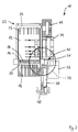
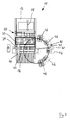
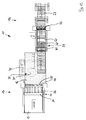
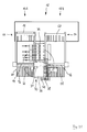
- FIG. 1 it comprises a first feed tray 12 formed of a plurality of roller rails, a dividing device (not visible) formed here as a saw with a first dividing line 14 ("sawing line"), and a first take-off table 16 likewise formed of a plurality of roller rails
- the first unloading table 16 may also be an air-cushion table, a table with roller conveyors, a belt conveyor or a conveyor belt.
- the actual first dividing line 14 is in FIG. 1 hidden by a pressure bar 18 and in FIG. 1 therefore indicated only by a dashed line.
- the dividing line 14 is formed by a gap in a machine table 20, which is arranged between the feed table 12 and the removal table 16. Through this gap, a saw blade can emerge upwards and be moved along the dividing line 14.
- To the panel splitter 10 further includes a first conveyor 22, which in the present case comprises a side rails (not numbered) movably held program slider 24 to which a plurality of collets 26 is attached, of which, for reasons of clarity, however, only one provided with a reference numeral is.
- a lying on the feed table 12 workpiece in the direction of the Aufteilline 14 and also against this direction along are moved to a direction indicated by a double arrow 28 conveying direction in a conventional manner.
- the longitudinal alignment device includes upwardly extendable alignment stops, which are arranged parallel to the Aufteilline 14 and allow alignment of the workpiece in the direction of the first conveying direction 28.
- the transverse aligner disposed on the cut line 14
- a workpiece lying on the feed table 12 can be pressed against a lateral angular ridge which bounds the feed table 12 sideways and is positioned exactly orthogonal to the split line 14, and thereby is aligned to the side.
- a Ausschubvorraum not shown here, the last machined workpiece is pushed onto the removal table 14.
- the panel sorter 10 further comprises a handling device 30, which in the present case is formed by a robot (not shown in detail) having a base 31 and an articulated to the base 31, with respect to the base 31 about a plurality of axes motorized and rotatable and a plurality comprising segmented robotic arm.
- a plate-shaped and substantially horizontal suction gripping device which is also not shown in the figure, is present.
- the suction gripping device is also mounted relative to the robot arm for rotation about a vertical axis.
- the suction gripping device is as a plate-shaped Truss structure designed and has on its underside a plurality of individual pneumatic suction cups, which can engage an upper surface of a plate-shaped workpiece.
- a working area of the robot 30 is shown as a dashed circle 32.
- the working area 32 is understood to be the area in which existing workpieces can be grasped and / or stored and / or transported by the robot 30.
- the working area 32 is thus a three-dimensional space area, which has approximately the shape of a hemisphere, in the center of which is a joint which connects the robot arm to the base 31.
- the plate dividing system 10 further comprises an active intermediate bearing 34 laterally of the feed table 10, and a passive intermediate bearing 36 laterally of the dividing line 14 and the extraction table 16.
- active at the active intermediate bearing 34 means that it is such an intermediate bearing. which is assigned its own intermediate storage conveyor. This may, for example, be a raised and lowered driven roller or belt conveyor.
- the intermediate storage conveyor device makes it possible for workpieces stored intermediately on the active intermediate storage 34 to be transported by this intermediate storage conveyor from the active intermediate storage 34 to the feed table 12, ie transversely to the first conveying direction 28. If appropriate, workpieces deposited on the active intermediate storage 34 can also be moved counter to the conveying direction just described.
- the adjective "passive" at the passive interim storage 36 means that it is a pure storage surface without such a special associated conveyor is.
- the panel dividing system 10 comprises a removal device in the form of a roller conveyor 38, in which also a labeling device 40 is also present.
- the removal device 38 is presently arranged laterally from the removal table 16, in the plan view of FIG. 1 So "south" of the robot 30. By means of the removal device 38 finished machined workpieces can be removed. By means of the labeling device 40 information can be applied to a workpiece.
- FIG. 1 One recognizes FIG. 1 in that the working area 32 of the robot 30 covers in plan view a part of the feed table 12, a part of the unloading table 16, a part of the passive intermediate storage 36 and a part of the active intermediate storage 34.
- a workpiece machined or separated by the splitting device can be taken by the robot 30 and either re-placed directly on the feed table 12 to be gripped by the first conveyor 22 and fed to the dividing line 14 for further processing, or can be picked up by the robot 30 be stored on the active intermediate storage 34 or the passive intermediate storage 36 for temporary storage. Since the working area 32 also covers part of the removal device 38, a finished workpiece can also be deposited by the robot 30 on the removal device 38.
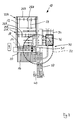
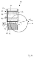
- a return conveyor device 44 is provided, with which the remaining workpieces produced during machining are conveyed back into a bearing (not shown) can.
- the return conveyor 44 may be, for example, a driven roller conveyor.
- the return conveyor 44 is present in FIG. 2 arranged above the active intermediate storage 34. Residual workpieces reach them by, for example, the active intermediate storage 34 also provides a delivery option to the return conveyor 44 through.
- the passive intermediate bearing 36 is arranged above the active intermediate bearing 34, but is significantly smaller than the active intermediate bearing 34, so that in the illustrated plan view it covers only the right lower quadrant of the active intermediate bearing 34.
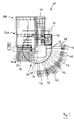
- plate dividing line 10 two first conveyors 22 A and 22 B with program pusher 24 A and 24 B and collets 26 A and 26 B available.
- the second first conveyor 22 B With the second first conveyor 22 B, a workpiece lying on the first feed table 12 can likewise be moved in the direction of the first dividing line 14.
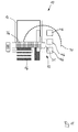
- a plurality of stacking areas 46 are shown, which are aligned approximately radially and side by side to the base 31 of the robot 30 approximately on a circular path, and which are at least partially covered by the working area 32 of the robot 30 in plan view.
- the stacking areas 46 may be, for example Lift pallets act.
- a removal facility is at the in FIG. 4 on the other hand, not shown.
- the robot 30 can thus also be used for unstacking the machined workpieces on the stacking areas 46.
- the stacking areas 46 are motor-movable in a direction radial to the base 31 of the robot 30 on rails 48, whereby manual mobility of the stacking areas 46 is also possible.
- the respective unstacking region 46 to be loaded is then moved radially inwards into the working region 32 of the robot 30. In this way, more stacking areas 46 can be provided than actually have space in the working area 32 of the robot 30 at the same time.
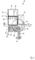
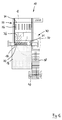
- Panel divider 10 shown is quite similar to that of FIG. 1 , however, the collets 26 on the program pusher 24 of the first conveyor 22 in the direction of the removal table 16 are performed extended. Their length is so dimensioned that they reach down to the removal table 16 when the program pusher 24 is in a position closest to the first removal table 16 end position. Thus, last workpieces in the split strip can also be fed from the first removal table 16 through a gap between the first split line 14 and the pressure bar 18 to the collets 26 of the first conveyor 22. It is thus possible with such a length of the collets that the robot 30 can pass a workpiece in a passage through the gap the program pusher 24.
- panel divider 10 shown is quite similar to that of FIG. 6 , however, the active intermediate bearing 34 is disposed above the feed table 12 and above the split line 14. The transport of stored on the active intermediate storage 36 workpieces on the feed table 12 must therefore be done by the robot 30.
- this panel dividing system 10 comprises both an active intermediate storage 34 and a passive intermediate storage 36. However, these are not arranged laterally, but above the dividing device or the dividing line 14 and above the feed table 12. In a first level above the feed table 12 and the Aufteilline 14, the active intermediate bearing 34 is arranged, and in a second plane above the active intermediate bearing 34, the passive intermediate bearing 36 is arranged. For the stacking areas 46, two full quadrants of the working area 32 are thus available. Incidentally, in the two intermediate storage 34 and 36, the labeling device 40 is arranged.
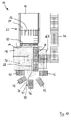
- FIG. 9 Shown embodiment of a panel splitter 10 is particularly compact and is therefore also referred to as a "compact cell". With her, those are out FIG. 6 known elongated collets present, but in the representation of FIG. 9 is hidden by the above the feed table 12 arranged active intermediate storage 34.
- the feed table 12 is seen in the direction of the first conveying direction 28 as compared to the previous embodiments executed significantly shortened.
- the intermediate active bearing 34 is disposed above the feed table 12 and the split line 14, whereas the passive intermediate bearing 6 and the robot 30 are disposed laterally of the split line 14 and the feed table 12.
- the base 31 of the robot 30 is shifted in the plan view slightly downwards compared to the previous embodiments, that is no longer directly to the side of the Aufteilline 14, but laterally from the unloading table 16.
- a labeling 40 is present .
- Also here last divided workpieces or located in the active intermediate bearing 34 or the passive intermediate bearing 36 workpieces for a next division of the first sampling table 16 ago by means of the robot 30 through the gap between the first Aufteilline 14 and the pressure bar 18 the collets 26 of the first conveyor 22 are supplied.
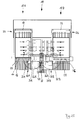
- plate divider 10 is similar to that of FIG. 9 again a relative "short" feed table 12 and a program slider 24 with long collets 26 available.
- the active intermediate bearing 34 is disposed above the split line 14, whereas the passive intermediate bearing 36 is disposed above the feed table 12.
- the labeling device 40 is arranged in the region of the passive intermediate bearing 36.
- the base 31 of the robot 30 is again laterally of the Aufteilline 14. If desired, also here last divided workpieces or located in the active intermediate storage 34 or the passive intermediate storage 36 workpieces for a next division of the first sampling table 16 ago by means of the robot 30 are fed through the gap between the first dividing line 14 and the pressure bar 18 to the collets 26 of the first conveyor 22.
- the panel splitter from FIG. 11 can be particularly inexpensive if it has neither an active intermediate storage nor a passive storage facility. Instead, not yet finished workpieces are stored directly on the unloading table 16.
- a passive intermediate bearing 36 may be provided above the Aufteilline 14.
- the first conveyor is of course available, but not shown for reasons of clarity. This variant can be retrofitted in particular with existing panel dividing systems 10.
- FIG. 13 shows a so-called "angle system".
- a second feed table 52 with a second conveyor 54 associated therewith a second dividing device with a second dividing line 56 and a second unloading table 58 are provided.
- the second Aufteilline 56 is at an angle of 90 ° to the first Aufteilline 14. so there are two part-Plattenaufteilanlagen 10a and 10b available.
- the second feed table 52 is designed as a roller conveyor and begins in a recess of the first removal table 16, the second conveyor 54 in turn has a program pusher 60 with collets 62.
- the base 31 of the robot 30 is arranged in the region of the first removal table 16. In this case, the working area 32 of the robot 30 covers in plan view a region of the first removal table 16 and a region of the second delivery table 52.
- the first splitting device is also referred to as a longitudinal saw
- the second splitting device is referred to as a cross saw.
- the first and the second cuts are made in such a plant in the saw, whereas the re-cuts are carried out in the cross saw.
- the robot 30 the finished by the longitudinal saw workpieces are transferred to the second feed table 52 of the cross saw.
- FIG. 14 shows a Plattenaufteilstrom 10 with present three mutually parallel part-Plattenaufteilanlagen, for the sake of clarity, only a partial panel splitter 10a is shown.
- the other partial panel dividing systems 10b and 10c are present to the left and indicated by corresponding arrows. It can be seen the active intermediate storage 34, the feed table 12, the Aufteilline 14 and the discharge table 16, which are all arranged in the same vertical plane.
- the robot 30 can also be seen, with its base 31 and the suction gripping device 64 shown in different positions in this figure.
- a conveying device 38 in the form of a roller conveyor is present in a plane above the vertical plane just mentioned, and a conveying device 66 is likewise arranged in a plane above said vertical plane and outside the plane of the conveying device 38.
- the output workpieces are transported from a non-visible bearing, both to the shown part-plate divider 10 a and to the other not shown part-Plattenaufteilanlagen 10 b and 10 c.
- the starting workpieces reach the active intermediate storage 34.
- the workpiece is moved onto the feed table 12. It is then decided whether the workpiece still has to be rotated by the robot 30 or whether the workpiece can be grasped immediately by the first conveyor 22 and fed to the dividing line 14.
- the feed table 12 may be relatively short, as in the embodiments already mentioned above.
- the removal device 38 is also used by all partial panel dividing systems in order to transport the finished workpieces as well as any remaining workpieces incurred during processing. Therefore, this lies in the working area 38 of the robot 30.
- FIG. 15 shows a panel splitter 10, which is very similar in itself to that of FIG. 13 , However, the first split line 14 and the second split line 56 are not arranged at an angle of 90 °, but at an angle of 0 ° to each other, ie parallel to each other.
- the robot 30 In order to realize cutting lines that are at an angle of 90 ° to each other (for example, cross section to longitudinal section), the robot 30 must rotate the workpiece by 90 ° when transferring from the longitudinal saw (first split line 14) to the cross saw (second split line 56) ,
- FIG. 16 describes a very simple Plattenaufteilstrom 10.
- a passive intermediate storage 36 is present, which is arranged above the pressure bar or above the Aufteilline 14 and relatively small dimensions.
- the in FIG. 16 also shown above the dividing line 14 and the pressure bar.
- the collets 26 are designed to be extended in the direction of the removal table 16 so that workpieces can also be fed from the removal table 16 through the gap between the machine table 20 and the pressure beam to the collets 26.
- the base 31 of the robot 30 is located in the region of the removal table 10, and is therefore integrated into these.
- the working area 32 of the robot 30 therefore essentially covers only the removal table 16 and the removal device 38.
- the robot 30 thus handles mainly workpieces in this embodiment, which lie on the discharge table 16 and are to put on the Abtransport issued 38.
- the first conveyor 22 may consist of two sub-conveyors, for example a relatively wide program pusher with a plurality of collets, the program pusher covers almost the entire width of the feed table 12, and a small , laterally mounted and movable carriage with only a collet, with the independent of the relatively broad program slide a narrow strip, the in FIG. 17 is located on the right edge of the feed table 12, can be moved.
- a relatively wide program pusher with a plurality of collets
- the program pusher covers almost the entire width of the feed table 12
- a small , laterally mounted and movable carriage with only a collet with the independent of the relatively broad program slide a narrow strip, the in FIG. 17 is located on the right edge of the feed table 12, can be moved.
- PC technology is known in the market as so-called "PC technology”.
- FIG. 18 Another possible embodiment of a panel splitter 10 shows FIG. 18 ,
- the base 31 of the robot 30 is displaceable in a horizontal plane. This is in FIG. 18 indicated by a possible displacement 68, and the corresponding work areas 32 are indicated by dashed circles. It can be seen that in the in FIG. 18 maximum lower horizontal position of the base 31 of the robot 30 of the work area 32 nor a portion of the removal table 16, but in particular five stacking 46 covers so that the robot 30 can be used in this position for stacking workpieces from the removal table 16 to the Abstapel Schemeen 46.
- the base 31 is located substantially in the center of the discharge table 16, so that the working area 32 a Covered most of the unloading table 16 and extends to the machine table 20.
- the robot 30 can pick up processed workpieces or feed workpieces through the gap between the machine table 20 and the pressure bar of the first conveyor 22 for further processing.
- the working area 32 is thus increased.
- he has the overall shape of an oval in plan view.
- the removal table 16 is in the in FIG. 18 shown plate dividing system 10 so large enough that it can serve as a passive intermediate storage for not yet finished workpieces.
- a so-called "spout” is integrated, which is basically a Abtransport adopted 38 can be removed from the finished machined workpieces from the robot 30 and deposited on the Abstapel Schemee 46.
- the actual removal table 16 which is designed here as an air cushion table, an additional removal table 16 B, wherein the boundary line between the actual removal table 16 and the additional removal table 16 B in extension of the (not shown) angular ruler.
- the return conveyor device 44 formed by a roller conveyor, remaining workpieces accumulated during processing can be conveyed back along an L-shaped path into a bearing.
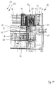
- FIG. 19 in turn, has first and second feed tables 12 and 52, first and second split lines 14 and 56, first and second take-off tables 16 and 58, and a first and a second take-off table second conveyor 22 and 54 on.
- first and second components two partial-panel-splitters 10 A and 10 B are created, which are in a FIG. 19 vertical line are mirror symmetrical and each have a robot, the two robots in FIG. 19 with 30 A and 30 B are designated.
- Corresponding work areas bear the reference numerals 32 A and 32 B.
- each of the partial panel dividers includes an active intermediate storage 34 A and 34 B located adjacent to each other in the center of the overall panel dividing plant 10.
- a return conveyor device 44 common to both partial panel dividing units 10A and 10B is also arranged for remaining workpieces obtained during processing and a removal unit 38 common to both partial panel dividing units 10 for finished workpieces.
- a labeling device 40 is present. On both sides of the Abtransport dressed 38 each have a passive intermediate storage 36 A and 36 B available.
- plate divider 10 is to that of FIG. 19 very similar. In her only missing the return conveyor. Instead, there is, so in the FIG. 20 upper area between the two part-Plattenaufteilanlagen, a normal plate bearing provided.
- FIG. 21 shows a Plattenaufteilstrom 10, which in turn has two partial Plattenaufteilanlagen 10 A and 10 B.
- a passive intermediate storage 36 is present, which can be used by both part-panel dividers 10 A and 10 B.
- a removal device 38 with a labeling device 40 is arranged in a vertical plane above the in FIG. 21
- the base 31 of the single robot 30 is arranged centrally between the two dividing or dividing line 14.
- the working area 32 thus covers part of the two removal tables 16 and 58, the passive intermediate storage 36, a part of the active intermediate storage 34 and a part of the two feed tables 12 and 52.
- the in FIG. 21 right part-Plattenaufteilstrom 10 B much easier and thus cheaper than the built in FIG. 21 left partial panel splitter 10 A. Thus costs are saved. This cost saving can be further increased if the in FIG. 21 right part-Plattenaufteilstrom 10 B is dimensioned much smaller than that in FIG. 21 left part-plate divider 10 A, that is, a smaller feed table 52, a smaller second conveyor 54, a shorter second Aufteilline 56 and a smaller second discharge table 58 has.
- the first dividing device of FIG. 21 left part-plate divider 10 A are preferably used for the implementation of longitudinal sections and cross sections
- the second splitting device of in FIG. 21 right part-plate divider 10 B is preferably used for the implementation of cross sections and re-cuts.
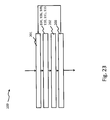
- FIG. 22 a method for dividing plate-shaped workpieces collectively the reference numeral 100.
- the method 100 is illustrated with reference to a flow chart and is performed by a control device - for example, a computer program on a control computer - the panel splitter 10.
- the division of the method 100 into different method steps is shown only as an example and does not mean that the method has to be performed exactly with this number of steps.
- the order of steps may also vary in other embodiments.
- a query at the same time to a in FIG. 22 take place as described above, For example, a query with the reference numeral 104 in parallel to a division by the reference numeral 103.
- the method 100 begins after a start block, for example with a first method step 101_1, in which a plate is removed from a plate storage, placed on the feed table 12 and transported by means of open collets 26 of the program pusher 24 to an alignment position.
- the plate can also be a workpiece to be split up, which has been produced, for example, in a previous division of a plate or a plate strip.
- the plate or the workpiece to be split is aligned by means of the longitudinal alignment device and clamped by means of the collets 26 of the program pusher 24.
- the workpiece to be split is additionally aligned by means of the transverse alignment device.
- the plate taken from the plate storage can be placed on the unloading table 16 and fed through the gap between the first Aufteilline 14 and the pressing device or the pressure bar 18 of the first conveyor 22.
- the robot 30 pushes the plate through the gap between the machine table 20 and the pressure bar 18 until the workpiece is aligned with the collets 26 and / or at the lateral angle ruler. Thereafter, the plate is gripped and clamped by the collets 26 and the robot 30 releases the plate.
- the plate is moved away from the Aufteilline 14 by means of the first conveyor 22 in a direction opposite to the division, until, for example, the plate directly into a position predefined for a first division or a trimming cut comes to rest.
- the plate or workpiece to be split is moved by means of the first conveyor 22 as far as the dividing line 14, so that in a next method step 103 a first division can be carried out.
- a trimming cut is made before the first division. This trimming cut is for clarity in the FIG. 22 not shown.
- a further method step 104 the separated workpiece is picked up by the robot 30 by means of the horizontal suction gripper device from the removal table 16, wherein correspondingly arranged pneumatic suction cups are activated according to the dimension of the workpiece.
- this activity of the robot 30 may also be part of further method steps 106 and 115, which will be explained below.
- the last possible detachable from the workpiece to be split and separated workpiece is pushed out by the collets 26 or the Ausschubvorraum on the unloading table 16.
- next method steps depend on whether the separated workpiece resulting from the division in method step 103 is a last workpiece which could be divided off from the plate or the workpiece to be split.
- a query "last workpiece?" If the result is a No (N), then, for example, proceeding to the process step 106, in which the last resulting separated workpiece, which is located on the discharge table 16, is handled by means of the robot 30, that the workpiece in the active intermediate storage 34, the passive intermediate storage 36 or is stored on the unloading table 16 at a predefined location, transported on the Abtransport issued 38 or stacked in a stacking 46 at a predefined location.
- the handling by means of the motor pivotally and rotatably mounted robot arm of the robot 30 preferably takes place on the shortest direct path between the unloading table 16 and one of the above storage locations on a first displacement path possibly on structures of the panel splitter 10 such as the pressure bar 18 or the Abtransport issued 38th time.
- An operator on the other hand, would have to walk around the components of the panel splitter 10 with the workpiece. If, on the other hand, the result in the method step 105 is a yes (J), then the method continues with the method step 114 described in one of the subsequent paragraphs.
- a further query is made as to whether the division of the plate currently being divided or of the workpiece to be divided is just finished. If the result is no (N), then step 102 continues. If, on the other hand, the result is a yes (J), then in a method step 108_1 a further query is made as to whether a division of another plate is pending and has priority. If the result is yes (J), then the method is continued with the method step 101_1.
- a continuation of the method follows with the method step 108_2, in which a further query takes place, if the current order planning or a picking currently being processed follows the further division of a previous split Workpiece, which is stored, provides.
- the method waits for an input of a new order by an operator or a transfer of a new order from a higher-level EDP system, in which several or all production lines in an industrial plant by means of a machine-to-machine Communication are networked with each other and based on the network access information in / out and derive higher-value functions, such as instructions for action (keyword "Industry 4.0").
- the method is not continued until the method step 108_1, when such an input or transmission has taken place.
- the process proceeds to a step 109 where the robot 30 manages an intermediate stored workpiece in the active intermediate storage 34, the passive intermediate storage 36 or on the discharge table 16 in which the robot 30 removes the intermediate workpiece from the active intermediate bearing 34 or the passive intermediate bearing 36 from a predefined location, and preferably by the shortest direct path on a second displacement path if necessary, moves over assemblies of the panel dividing installation 10, such as the pressure bar 18 or the removal device 38, in the direction of a predefined, programmed storage position of the removal table 16.
- the handling by the robot 30 takes place in such a manner that the intermediate workpiece is oriented with respect to a predefined programmed orientation and stored in the predefined programmed storage position of the removal table 16.
- the method 100 is continued with a method step 111, in which the intermediate workpiece or a workpiece that has just been divided or processed is fed through the gap between the first split line 14 and the pressing device or the pressure bar 18 to the first conveyor 22.
- the robot 30 pushes the workpiece through the gap between the machine table 20 and the pressure bar 18 until the workpiece is aligned with the collets 26 and / or at the lateral angle ruler.
- a next method step 112 the workpiece is gripped and clamped by the collets 26 and the robot 30 releases the workpiece.
- the workpiece is transported back by means of the first conveyor 22 in a direction opposite to the division away from the split line 14 until, for example, the workpiece comes to rest directly in a predefined position (for example, first) or a trimming cut , In such a case, the method 100 is continued directly with the method step 103.
- step 114 If the workpiece resulting from the division 103 is a last workpiece that could be divided off from the plate, then a query is made in method step 114 as to whether the workpiece itself should be split further. If the result is no (N), then step 106 continues. If, on the other hand, the result is yes (J), then in a step 115, the workpiece is handled by the robot 30, in which the workpiece is preferably rotated by 90 °. The method 100 is then continued with the method step 111.
- the same appropriately configured robot 30 is used to intermediate workpieces to position on the removal table 16 for further division and fed through the gap between the first split line 14 and the pressing device or the pressure bar 18 of the first conveyor 22.
- the same robot 30, which has been correspondingly configured is used to also stack off workpieces and / or place workpieces on the removal device 38.
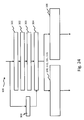
- an optional extension of the method 100 immediately before and after the handling steps 104, 106, 109, 110, 111 and / or 115 of the robot 30 is shown to time periods for performing the handling steps 104, 106, 109, 110, 111 and / or 115 to measure and store in an electronic memory.
- the extension of the method 100 can preferably be used during the run-in phase of the panel splitter 10.
- an additional method step 201 simultaneously with a beginning of one of the handling steps 104, 106, 109, 110, 111 and / or 115 by the robot 30, a time measurement by the control device of the panel splitter 10 is started.
- the robot 30 can preferably be moved to a predefined reference position. Then, the respective handling step 104, 106, 109, 110, 111 and / or 115 is performed.
- a time measurement is stopped by the control device of the panel splitter 10 simultaneously with a termination of one of the handling steps 104, 106, 109, 110, 111 and / or 115 by the robot 30. Preferably, the time measurement is stopped as soon as the robot 30 has reached the reference position again.
- a measured period of time is assigned to the executed handling step 104, 106, 109, 110, 111 or 115 and stored, for example in the form of a table in an electronic memory, wherein a first column of the table is an identifier for the respective handling step 104, 106, 109 , 110, 111 and 115, respectively, and a second column contains the measured time duration.
- a plurality of measured time durations could be stored for the same handling step 104, 106, 109, 110, 111 and 115, respectively, and an average over the measured time durations could be formed and stored in a further table column. The procedure is then followed by the respective in FIG. 22 process step shown continued.
- FIG. 24 shows a further optional extension of the method 100 based on the extension of the method 100 according to FIG. 23 For example, which takes place in parallel to the time of the splitting process step 103, the productivity of the panel splitter 10 further increase.
- the extension of the method 100 can preferably be used after the retraction phase of the panel splitter 10.
- next manipulation steps required by the robot 30 are queried based on, for example, a current split order for a customer or a piece of furniture from the quantity of the handling steps 104, 106, 109, 110, 111, 115. Based on the resulting in this query handling steps 104, 106, 109, 110, 111, 115, the associated stored time periods are retrieved from the electronic memory.
- the next handling step to be carried out with the robot 30 is calculated, for example, under the boundary conditions that the plate dividing system 10 is continuously supplied with workpieces for division and no workpieces located on the removal table 16 hinder the division and dispensing of another workpiece.
- the queries of method steps 105, 107, 108 and 114 are carried out, for example, as sub-method steps of method step 303.
- an instruction is transferred to the robot 30 for the calculated next handling step to be carried out.
- the result could be, for example, that an intermediate storage or a stacking of a workpiece in step 106 should take place before the feeding of another workpiece through the gap between the split line 14 and the pressing device 18, so that for just in dividing workpiece a free tray on the removal table 16 is present.
- FIG. 25 schematically shows with reference to another flowchart, an embodiment of the method step 106, in which is stacked, by means of the robot 30, in particular with respect to the in FIG. 5
- the number of sub-process steps and the order of the sub-process steps are reproduced here only by way of example.
- a predefined stacking area 46 is characterized, for example, in that the stacking area 46 is assigned to a picking for a specific customer or for a specific piece of furniture.
- radial arrangement of the Abstapel Schemee 46 more Abstapel Schemee 46 can be provided outside of the working area 32 of the robot 30 in a parking position than within the working area 32 of the robot 30 in a Abskysposition can be positioned.
- only every second stacking area 46 may be positioned in the stacking position.
- only one of the stacking regions 46 is positioned at the stacking position. In the following, it is assumed by way of example that only one stacking region 46 is permissible or can be positioned in the working region 32 of the robot 30.
- the method step 106 proceeds to a sub-method step 106_7.
- sub-method step 106_2 it is checked whether another stacking area 46 is in the stacking position. If the result is Yes (J), then sub-process step 106_3 follows. If, on the other hand, the result is a No (N), then it proceeds to a sub-process step 106_4.
- the stacking area 46 currently located in the working area 32 of the robot 30 is moved, preferably program-controlled and motor-driven, from the stacking position into the parking position, radially outward.
- the predefined stacking area 46 is preferably moved programmatically and driven by a motor from the parking position radially inwards into the working area 32 of the robot 30.
- the robot 30 stacks the Workpiece in a predefined programmed area of the stacking 46.
- a sub-process step 106_6 in which it is checked whether other workpieces that may result from a division in method step 103 must be stacked. If the result of this check is a No (N), then the stacking area 46 located in the working area 32 of the robot 30 is moved from the stacking position into the parking position radially outward, preferably in a program-controlled and motor-driven manner, in a sub-method step 106_8 analogously to the sub-method step 106_3 and the stacking is terminated until new workpieces are to be produced and destacked with the panel splitter 10. On the other hand, if the result of this check is Yes (J), then the stacking process step 106 is continued with the sub-process step 106_1.
- sub-method step 106_7 it is checked whether the predefined stacking area 46 located in the stacking position still has sufficient capacity for destacking a further workpiece. If the result of this check is Yes (J), then the stacking process step 106 proceeds to the sub-process step 106_5. If, on the other hand, the result of the check is a No (N), then sub-method steps 106_3 and 106_4 follow, in which the stacking area 46 filled to the capacity limit preferably moves from the stacking position into the park position radially outwards, preferably program-controlled and motor-driven, and another predefined stacking area 46 with sufficient capacity preferably is driven programmatically and motor driven from the parking position radially inwardly into the working area 32 of the robot 30.
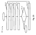
- FIG. 26 A further flowchart of a further exemplary embodiment for the stacking process step 106 by means of the robot 30, with particular reference to FIGS FIG. 18 shown plate divider 10 shown.
- the number of sub-process steps and the order of the sub-process steps are reproduced here only by way of example.
- the stacking process step 106 begins with the fact that a workpiece just divided in method step 103 or a plurality of workpieces just split in method step 103 are deposited by the robot 30 on the removal device 38.
- the base of the robot 30 is located, for example, in the middle of the removal table 16 or generally in a first end point of the displacement path 68 (FIG. FIG. 18 ) near the split line 14, so that the work area 32 of the robot 30 is arranged so that the robot 30 can pick up processed workpieces from the take-off table 16 or feed workpieces back through the nip between the machine table 20 and the pressure bar 18 to the first conveyor 22 for further processing.
- a further sub-process step 106_11 the stored workpiece or the stored workpieces are transported away by means of the removal device 38 in the direction of the stacking regions 46.
- the base of the robot 30 becomes along the displacement path 68 shifted to a second end of the displacement path 68 remote from the Aufteilline 14 in the region of the Abstapel Schemee 46.
- the deposited workpiece or the stored workpieces are unstacked in a predefined programmed stacking region 46 of the stacking regions 46 in a sub-process step 106_13.
- a next sub-process step 106_14 is checked whether more workpieces must be stacked. If the result of the check is Yes (J), then in a subsequent sub-process step 106_15, the base of the robot 30 is again shifted to the first end point of the displacement path 68 toward the split line 14. The stacking process step 106 is then continued with the sub-process step 106_10. If, on the other hand, the result of the check is No (N), then the stacking ends or the stacking is suspended until workpieces are again made by the panel splitter 10, which are ready-divided and can be stacked.
- FIGS. 22 to 26 described method steps are realized by appropriate functional means, technical means and configurations of the panel splitter 10 and the robot 30 and can be claimed accordingly.
- these functional devices, technical means and configuration, in each case based on the Plattenaufteilstrom 10 and the robot 30 is not shown or explained again, because a person skilled in the art can be based on the above process description and its general expertise, the corresponding functional equipment, technical Means and configurations of the panel splitter 10 and the robot 30 realize.
Abstract
Die Erfindung betrifft eine Plattenaufteilanlage (10) zum Aufteilen von plattenförmigen Werkstücken, mit einem ersten Zuführtisch (12), mindestens einer ersten Aufteileinrichtung mit einer ersten Aufteillinie (14), einem ersten Entnahmetisch (16) und mindestens einer ersten Fördereinrichtung (22), mit der ein auf dem Zuführtisch (12) liegendes Werkstück in Richtung zur ersten Aufteillinie (14) hin bewegt werden kann. Erfindungsgemäß weist sie mindestens eine Handhabungseinrichtung zum Handhaben von bereits bearbeiteten oder zur Bearbeitung vorgesehenen Werkstücken auf, die einen Roboter (30) umfasst, der eine Basis (31) und einen Arbeitsbereich (32) aufweist. Die Erfindung betrifft ferner ein Verfahren zum Aufteilen von plattenförmigen Werkstücken.The invention relates to a panel dividing installation (10) for dividing plate-shaped workpieces, having a first feed table (12), at least one first dividing device with a first dividing line (14), a first removal table (16) and at least one first conveying device (22) a workpiece lying on the feed table (12) can be moved in the direction of the first dividing line (14). According to the invention, it has at least one handling device for handling workpieces already machined or intended for processing, which comprises a robot (30) having a base (31) and a working area (32). The invention further relates to a method for dividing plate-shaped workpieces.
Description
Die Erfindung betrifft eine Plattenaufteilanlage zum Aufteilen von plattenförmigen Werkstücken nach dem Oberbegriff des Anspruchs 1 und ein Verfahren zum Aufteilen von plattenförmigen Werkstücken mittels einer Plattenaufteilanlage.The invention relates to a Plattenaufteilanlage for dividing plate-shaped workpieces according to the preamble of claim 1 and a method for dividing plate-shaped workpieces by means of a Plattenaufteilanlage.
Derartige Plattenaufteilanlagen sind sowohl vom Markt her als auch aus der
Dabei ist es bekannt, ein Werkstück durch insgesamt zwei oder mehr auf Teilvorgänge aufzuteilen. Der erste Aufteilvorgang wird auch als Längsschnitt, der zweite Aufteilvorgang als Querschnitt, und der dritte Aufteilvorgang als Nachschnitt bezeichnet.It is known to divide a workpiece by a total of two or more on sub-operations. The first splitting operation is also referred to as a longitudinal section, the second splitting operation as a cross section, and the third splitting operation as a re-cut.
Aufgabe der vorliegenden Erfindung ist es, eine Plattenaufteilanlage der eingangs genannten Art so weiterzubilden, dass sie besonders wirtschaftlich arbeitet.Object of the present invention is to develop a panel splitter of the type mentioned so that it works very economically.
Diese Aufgabe wird durch eine Plattenaufteilanlage mit den Merkmalen des Anspruchs 1 und durch ein Verfahren zum Aufteilen von plattenförmigen Werkstücken mit den Merkmalen des Anspruchs 18 gelöst. Vorteilhafte Weiterbildungen sind in Unteransprüchen angegeben. Darüber hinaus finden sich für die Erfindung wichtige Merkmale in der nachfolgenden Beschreibung und in der Zeichnung. Die Merkmale können dabei sowohl in Alleinstellung als auch in ganz unterschiedlichen Kombinationen für die Erfindung wichtig sein.This object is achieved by a panel splitter with the features of claim 1 and by a method for splitting plate-shaped workpieces with the features of
Die erfindungsgemäße Plattenaufteilanlage und das erfindungsgemäße Verfahren haben den Vorteil, dass die Handhabung von bereits bearbeiteten oder zur Bearbeitung vorgesehenen Werkstücken nicht mehr durch eine Bedienperson erfolgen muss, sondern automatisiert durch einen Roboter vorgenommen wird. Hierdurch wird zum einen die Effizienz der Plattenaufteilanlage gesteigert, da ein Roboter naturgemäß keine Konzentrationsschwächen oder Ermüdungserscheinungen kennt. Auch kann ein Roboter bei entsprechender Auslegung die zum Teil schweren Werkstücke problemlos handhaben. Ein Roboter kann ferner im 24 Stunden Betrieb arbeiten. Darüber hinaus wird durch den Einsatz eines Roboters auch die Betriebssicherheit der Anlage verbessert, da keine Personen mehr bei der Handhabung der Werkstücke gefährdet werden. Auch hat ein Roboter einen größeren Arbeitsbereich, da die Armlänge des Roboters maßgeschneidert für die entsprechende Plattenaufteilanlage ausgelegt werden kann.The panel dividing plant according to the invention and the method according to the invention have the advantage that the handling of workpieces already machined or intended for processing no longer has to be performed by an operator, but is carried out automatically by a robot. In this way, on the one hand, the efficiency of the panel-splitting installation is increased, since a robot inherently has no concentration deficiencies or Fatigue phenomena knows. Also, a robot can easily handle the sometimes heavy workpieces with appropriate design. A robot can also work 24 hours a day. In addition, the use of a robot also improves the operational safety of the plant, as no persons are endangered when handling the workpieces. Also, a robot has a larger work area because the arm length of the robot can be tailored for the corresponding panel sizing plant.
Der Roboter kann aber auch an Stelle von bisher eingesetzten automatischen Fördereinrichtungen verwendet werden, beispielsweise Schiebern oder Förderbändern oder angetriebenen Rollenbahnen. Gegenüber solchen automatischen Fördereinrichtungen hat ein Roboter dann, wenn es sich um einen mehrachsigen Roboter mit einer ausreichenden Anzahl von Freiheitsgraden handelt, den Vorteil, dass er nicht nur lineare Bewegungen in einer festgelegten Ebene durchführen kann, sondern das Werkstück beinahe beliebig von einer Position zu einer anderen transportieren und während dieses Transports beispielsweise auch drehen kann.The robot can also be used in place of previously used automatic conveyors, such as sliders or conveyor belts or driven roller conveyors. Compared to such automatic conveyors, if a robot is a multiaxial robot having a sufficient number of degrees of freedom, the advantage is that not only can it perform linear movements in a fixed plane, but the workpiece can be moved almost arbitrarily from one position to another transport and during this transport, for example, can rotate.
Vorgeschlagen wird, dass der Arbeitsbereich des Roboters in einer Draufsicht vorzugsweise mindestens zum Teil einen Bereich des ersten Entnahmetisches überdeckt. An dieser Stelle ist der Einsatz eines Roboters besonders wirksam, da er im Bereich des Entnahmetisches beispielsweise ein Werkstück entnehmen und einer Abstapelung zu führen kann, oder ein bearbeitetes Werkstück entnehmen, drehen und der Aufteileinrichtung für eine weitere Bearbeitung zuführen kann, etc.It is proposed that the working area of the robot in a plan view preferably at least partially cover a region of the first removal table. At this point, the use of a robot is particularly effective, since it can remove, for example, a workpiece in the region of the removal table and can lead to a stacking, or remove a machined workpiece, rotate and perform the splitting device for further processing, etc.
Vorgeschlagen wird ferner, dass sie mindestens eine Rückfördereinrichtung aufweist, mit der bei der Bearbeitung entstandene Rest-Werkstücke in ein Lager zurück gefördert werden können. Eine solche Plattenaufteilanlage arbeitet ebenfalls besonders effizient, da die Rückforderung ebenfalls automatisiert ist.It is further proposed that it has at least one return conveyor, with the resulting during processing residual workpieces can be promoted back into a warehouse. Such a panel splitter also works very efficiently, since the recovery is also automated.
Vorgeschlagen wird ferner, dass sie eine weitere erste Fördereinrichtung aufweist, mit der ein auf dem ersten Zuführtisch liegendes Werkstück in Richtung zur ersten Aufteillinie hin bewegt werden kann. Auch dies wirkt effizienzsteigernd, da ein neues Werkstück bereits eingeschoben werden kann, während ein anderes noch Werkstück aufgeteilt wird.It is further proposed that it has a further first conveying device with which a workpiece lying on the first feed table can be moved in the direction of the first dividing line. This also increases efficiency, since a new workpiece can already be inserted while another workpiece is still being split.
Vorgeschlagen wird ferner, dass die beiden ersten Fördereinrichtungen jeweils einen Programmschieber mit Spannzangen umfassen. Dies ist eine besonders erprobte und zuverlässige Ausgestaltung für die ersten Fördereinrichtungen.It is further proposed that the two first conveyors each comprise a program pusher with collets. This is a particularly proven and reliable design for the first conveyors.
Vorgeschlagen wird ferner, dass der Arbeitsbereich des Roboters in der Draufsicht mindestens zum Teil einen Abstapelbereich überdeckt. Die Flexibilität des Roboters wird so auch für die Abstapelung genutzt.It is further proposed that the working area of the robot in plan view at least partially covers a stacking area. The flexibility of the robot is also used for stacking.
Vorgeschlagen wird ferner, dass mindestens ein Abstapelbereich in einer Richtung radial zur Basis des Roboters, insbesondere auf Schienen, beweglich ist. Hierdurch wird die Abstapelkapazität erhöht.It is further proposed that at least one stacking area is movable in a direction radial to the base of the robot, in particular on rails. This increases the stacking capacity.
Vorgeschlagen wird ferner, dass seitlich und/oder oberhalb vom ersten Zuführtisch und/oder ersten Entnahmetisch und/oder oberhalb von der ersten Aufteillinie ein passives Zwischenlager vorhanden ist, und dass der Arbeitsbereich des Roboters in der Draufsicht mindestens zum Teil einen Bereich des Zwischenlagers überdeckt. Durch ein passives Zwischenlager wird eine preiswerte Möglichkeit zum Puffern von halbfertigen Werkstücken (beispielsweise solchen Werkstücken, an denen später noch Nachschnitt durchgeführt werden sollen) geschaffen. Eine Anordnung eines solchen Zwischenlagers oberhalb vom ersten Zuführtisch, vom ersten Entnahmetisch und/oder von der ersten Aufteillinie ist besonders platzsparend.It is further proposed that laterally and / or above the first feed table and / or first take-off table and / or above the first split line, a passive Intermediate storage is present, and that the working area of the robot in plan view at least partially covers a portion of the intermediate storage. A passive intermediate storage creates a cost-effective possibility for buffering half-finished workpieces (for example, those workpieces which are to be reworked later). An arrangement of such an intermediate storage above the first feed table, from the first discharge table and / or from the first dividing line is particularly space-saving.
Vorgeschlagen wird ferner, dass oberhalb vom ersten Zuführtisch ein aktives Zwischenlager angeordnet ist, dem eine eigene Fördereinrichtung zugeordnet ist. Dies erhöht nochmals die Anlageneffizienz, da die dem aktiven Zwischenlager zugeordnete eigene Fördereinrichtung ein zwischengelagertes Werkstück fördern kann, während der Roboter ein anderes Werkstück handhabt.It is also proposed that above the first feed table, an active intermediate storage is arranged, which is assigned its own conveyor. This again increases the plant efficiency, since the own intermediate conveyor associated own conveyor can promote an intermediate stored workpiece, while the robot handles another workpiece.
Vorgeschlagen wird ferner, dass das aktive Zwischenlager oberhalb von dem ersten Zuführtisch und das passive Zwischenlager oberhalb von dem aktiven Zwischenlager angeordnet sind, vorzugsweise derart, dass ein Bereich des aktiven Zwischenlagers nach oben hin für den Roboter zugänglich ist. Die Zwischenlager bilden also eine Art "Stapel", wodurch eine besonders platzsparende Bauweise der Plattenaufteilanlage realisiert wird.It is furthermore proposed that the active intermediate storage be arranged above the first feed table and the passive intermediate storage above the active storage facility, preferably such that an area of the active storage facility is accessible upwardly for the robot. The intermediate storage thus form a kind of "stack", whereby a particularly space-saving design of the panel splitter is realized.
Vorgeschlagen wird ferner, dass seitlich vom ersten Zuführtisch ein aktives Zwischenlager angeordnet ist, dem eine eigene Fördereinrichtung zugeordnet ist, und oberhalb eines Teils des aktiven Zwischenlagers ein passives Zwischenlager angeordnet ist. Auch dies führt zu einer besonders platzsparenden und dennoch effizienten Plattenaufteilanlage.It is also proposed that an active intermediate bearing is arranged laterally from the first feed table, to which a separate conveying device is assigned, and above a part of the active intermediate bearing a passive intermediate bearing is arranged. This too leads to a particularly space-saving, yet efficient panel dividing system.
Vorgeschlagen wird ferner, dass die erste Fördereinrichtung einen Programmschieber mit Spannzangen umfasst, welche in Richtung zum ersten Entnahmetisch eine solche Länge aufweisen, dass sie bis auf den ersten Entnahmetisch reichen, wenn der Programmschieber sich in einer zum ersten Entnahmetisch nächstliegenden Endstellung befindet. Hierdurch wird es vereinfacht, ein zu bearbeitendes Werkstück vom Entnahmetisch her der ersten Fördereinrichtung zuzuführen.It is further proposed that the first conveyor comprises a program pusher with collets, which in the direction of the first discharge table have a length such that they extend to the first removal table, when the program pusher is in an end position closest to the first removal table. This makes it easier to feed a workpiece to be machined from the unloading table to the first conveyor.
In Weiterbildung hierzu wird vorgeschlagen, dass der Roboter so angeordnet und ausgebildet ist, dass der Roboter ein, insbesondere auf dem ersten Entnahmetisch liegendes, Werkstück handhaben und durch einen Spalt zwischen der ersten Aufteillinie und einer Andrückeinrichtung der ersten Fördereinrichtung zuführen kann. Beispielsweise muss der Roboter ausreichend nahe zur ersten Aufteillinie angeordnet sein, und er muss in der Lage sein, ein flach auf dem Entnahmetisch liegendes Werkstück schiebend zur ersten Fördereinrichtung hin zu transportieren. Hierzu muss beispielsweise ein Roboterarm über Gelenke mit ausreichenden Freiheitsgraden verfügen, und der Roboter muss ein flach auf dem Entnahmetisch liegendes Werkstück an dessen Oberseite halten können. Damit kann das Zuführen eines Werkstücks vom Entnahmetisch her durch den Roboter erfolgen. Dies erhöht die Anlageneffizienz bei gleichzeitig sehr einfachem Aufbau der Plattenaufteilanlage.In a further development, it is proposed that the robot is arranged and configured so that the robot can handle a workpiece, in particular lying on the first removal table, and feed it through a gap between the first split line and a pressure device of the first conveyor. For example, the robot must be located sufficiently close to the first split line, and it must be able to push a flat lying on the removal table workpiece sliding towards the first conveyor out. For this purpose, for example, a robot arm must have joints with sufficient degrees of freedom, and the robot must be able to hold a flat lying on the removal table workpiece on the top. Thus, the feeding of a workpiece from the unloading table can be done by the robot. This increases the efficiency of the system while at the same time simplifying the design of the panel dividing system.
Es wird weiterhin vorgeschlagen, dass die Länge der Spannzangen an das Zuführen des Werkstücks durch den Spalt angepasst ist, so dass der Roboter das Werkstück in einfacher Weise dem Programmschieber übergeben kann.It is further proposed that the length of the collets on the feeding of the workpiece through the gap is adapted so that the robot can easily pass the workpiece to the program pusher.
Vorgeschlagen wird ferner, dass der erste Entnahmetisch eine Zwischenlagerfunktion aufweist. Dies wird beispielsweise durch eine ausreichend große Dimensionierung des ersten Entnahmetisches geschaffen, derart, dass zwischengelagerte Werkstücke die Handhabung von vorläufig oder endgültig bearbeiteten Werkstücken auf dem Entnahmetisch nicht behindern. Im Grunde kann damit eine zu einer herkömmlichen Plattenaufteilanlage ganz ähnliche Plattenaufteilanlage eingesetzt werden, bei der zusätzlich ein Roboter angeordnet und eventuell noch der Entnahmetisch erweitert wird. Dies ist eine auch nachrüstbare Variante, die die Vorteile eines Roboters bei herkömmlichen Plattenaufteilanlagen nutzbar macht.It is further proposed that the first discharge table has an intermediate storage function. This is created for example by a sufficiently large dimensioning of the first unloading table, such that intermediate stored workpieces do not hinder the handling of provisionally or finally machined workpieces on the unloading table. Basically, this can be used to a conventional Plattenaufteilanlage very similar Plattenaufteilanlage in which additionally arranged a robot and possibly even the removal table is extended. This is a retrofittable variant, which makes the advantages of a robot usable in conventional panel dividing systems.
Vorgeschlagen wird ferner, dass die Basis des Roboters im Bereich des ersten Entnahmetisches angeordnet ist. Der Roboter ist somit quasi in den Entnahmetisch integriert bzw. vom Entnahmetisch umgeben. Er kann also besonders effizient für die Handhabung von auf dem Entnahmetisch liegenden Werkstücken eingesetzt werden.It is also proposed that the base of the robot is arranged in the region of the first removal table. The robot is thus virtually integrated into the removal table or surrounded by the removal table. It can therefore be used particularly efficiently for the handling of workpieces located on the removal table.
Vorgeschlagen wird ferner, dass die Basis des Roboters oberhalb von der ersten Aufteillinie angeordnet ist. Damit kann der Roboter sowohl den Entnahmetisch als auch den Zuführtisch optimal "bedienen", und ist darüber hinaus platzsparend untergebracht, so dass die Standfläche der Plattenaufteilanlage nicht vergrößert wird.It is also proposed that the base of the robot is arranged above the first split line. Thus, the robot can optimally "operate" both the removal table and the feed table, and is also accommodated in a space-saving manner so that the footprint of the panel dividing system is not increased.
Vorgeschlagen wird ferner, dass die Basis des Roboters horizontal beweglich ist. Hierdurch wird der Arbeitsbereich des Roboters auf einfache Art und Weise vergrößert.It is also proposed that the base of the robot is horizontally movable. As a result, the working range of the robot is increased in a simple manner.
Besonders vorteilhaft ist dabei, wenn die horizontale Beweglichkeit des Roboters parallel zur Förderrichtung der ersten Fördereinrichtung ist.It is particularly advantageous if the horizontal mobility of the robot is parallel to the conveying direction of the first conveyor.
Vorgeschlagen wird ferner, dass die Plattenaufteilanlage mindestens einen zweiten Zuführtisch mit einer diesem zugeordneten zweiten Fördereinrichtung, mindestens eine zweite Aufteileinrichtung mit einer zweiten Aufteillinie, und mindestens einen zweiten Entnahmetisch umfasst, wobei die erste Aufteillinie zu der zweiten Aufteillinie in einem Winkel angeordnet ist, der in einem Bereich von 0° bis 180° liegt. Liegt der Winkel bei 0°, sind die "Teil-Plattenaufteilanlagen" nebeneinander und parallel angeordnet. Liegt der Winkel bei 90°, handelt es sich um eine sogenannte "Winkelanlage", und liegt der Winkel bei 180°, sind die beiden "Teil-Plattenaufteilanlagen" parallel zueinander, aber gegensinnig angeordnet. Eine solche Plattenaufteilanlage hat mindestens eine verdoppelte Kapazität.It is further proposed that the panel dividing installation comprise at least one second feed table with a second conveying device associated therewith, at least one second dividing device with a second dividing line, and at least one second unloading table, wherein the first dividing line is arranged at an angle to the second dividing line a range of 0 ° to 180 °. If the angle is 0 °, the "partial panel dividing systems" are arranged side by side and in parallel. If the angle is at 90 °, it is a so-called "angle system", and if the angle is 180 °, the two "partial panel splitters" are arranged parallel to each other but in opposite directions. Such a panel splitter has at least a doubled capacity.
In Weiterbildung hierzu wird vorgeschlagen, dass der Arbeitsbereich des Roboters in der Draufsicht mindestens zum Teil einen Bereich des ersten Entnahmetisches und mindestens zum Teil einen Bereich des zweiten Zuführtisches überdeckt. Der Roboter kann somit ein auf dem ersten Entnahmetisch liegendes Werkstück auf den zweiten Zuführtisch bewegen, so dass eine bisher erforderliche komplexe Übergabestation nicht mehr erforderlich ist. Dies gilt insbesondere bei einer sogenannten "Winkelanlage", bei der die zweite Aufteillinie in einem Winkel von 90° gegenüber der ersten Aufteillinie angeordnet ist.In a further development, it is proposed that the working area of the robot in plan view at least partially covers a region of the first removal table and at least partially a region of the second delivery table. The robot can thus move a lying on the first removal table workpiece on the second feed, so that a previously required complex transfer station is no longer required. This applies in particular to a so-called "angular installation", in which the second dividing line is arranged at an angle of 90 ° with respect to the first dividing line.
Eine Gesamtanlage mit besonders hoher Kapazität wird dadurch geschaffen, dass die Zuführtische, Aufteileinrichtungen und Entnahmetische nebeneinander und parallel zueinander angeordnet sind, wodurch vorzugsweise eine Vielzahl von Teil-Plattenaufteilanlagen geschaffen wird, dass sämtlichen Zuführtischen eine gemeinsame Zuführeinrichtung zugeordnet ist.An overall system with particularly high capacity is created by the feed tables, Dividing devices and unloading tables are arranged side by side and parallel to each other, whereby preferably a plurality of part-Plattenaufteilanlagen is provided that all feed tables is assigned a common feeder.
In Weiterbildung hierzu wird vorgeschlagen, dass jedem Zuführtisch ein aktives Zwischenlager zugeordnet ist, welches in der gleichen vertikalen Ebene wie die Zuführeinrichtung liegt. Eine solche Plattenaufteilanlage ist trotz der hohen Kapazität vergleichsweise klein.In a further development, it is proposed that each feed table is assigned an active intermediate storage, which lies in the same vertical plane as the feed device. Such a panel splitter is comparatively small despite the high capacity.
In nochmaliger Weiterbildung hierzu wird vorgeschlagen, dass eine Abtransporteinrichtung zum Abtransportieren bearbeiteter Werkstücke vertikal in einer anderen Ebene als die Zuführeinrichtung angeordnet ist. Auf diese Weiterbildung führt zu einer verhältnismäßig kleinen Gesamtanlage.In a further development for this purpose, it is proposed that a removal device for transporting processed workpieces is arranged vertically in a different plane than the feed device. In this development leads to a relatively small overall system.
Vorgeschlagen wird ferner, dass die Plattenaufteilanlage zwei Zuführtische mit jeweiligen Fördereinrichtungen, zwei Aufteileinrichtungen und zwei Entnahmetische aufweist, die nebeneinander und parallel zueinander angeordnet sind, und dass sie einen Roboter umfasst, dessen Arbeitsbereich in der Draufsicht beide Zuführtische und beide Entnahmetische zumindest teilweise überdeckt. Hierdurch wird eine Plattenaufteilanlage mit hoher Kapazität geschaffen, die vergleichsweise preiswert ist, da lediglich ein Roboter für die Handhabung der Werkstücke in beiden parallelen Anlagen verwendet wird.It is furthermore proposed that the panel-dividing installation have two feed tables with respective conveying devices, two dividing devices and two removal tables, which are arranged side by side and parallel to one another, and that it comprises a robot whose working region, in plan view, at least partially covers both feed tables and both discharge tables. As a result, a high-capacity plate-cutting machine is provided, which is comparatively inexpensive, since only one robot is used for handling the workpieces in both parallel systems.
Vorgeschlagen wird ferner, dass die Zuführtische, Aufteileinrichtungen und Entnahmetische nebeneinander und parallel zueinander angeordnet sind, und dass die Plattenaufteilanlage zwei Roboter umfasst, die so angeordnet sind, dass sich deren Arbeitsbereiche in der Draufsicht überlappen. Eine solche Plattenaufteilanlage gestattet aufgrund des jeder Teil-Plattenaufteilanlage zugeordneten eigenen Roboters nicht nur einen kombinierten, sondern auch einen unabhängigen Betrieb der beiden Teil-Plattenaufteilanlagen, wodurch die Flexibilität des Betriebs der Gesamtanlage erhöht wird.It is further proposed that the feed tables, dividing devices and discharge tables are arranged side by side and parallel to each other, and that the Plattenaufteilanlage two robots comprises, which are arranged so that their work areas overlap in plan view. Such a panel divider allows, due to the own robot associated with each panel divider, not only a combined operation but also an independent operation of the two panel divider units, thereby increasing the flexibility of the operation of the whole unit.
In Weiterbildung hierzu wird vorgeschlagen, dass die Plattenaufteilanlage eine gemeinsame Abtransporteinrichtung für bearbeitete Werkstücke und/oder eine gemeinsame Zuführeinrichtung für zu bearbeitende Werkstücke aufweist, wobei die gemeinsame Abtransporteinrichtung und/oder die gemeinsame Zuführeinrichtung vorzugsweise zwischen den beiden Teil-Plattenaufteilanlagen angeordnet sind. Dies reduziert sowohl den notwendigen Bauraum als auch die Kosten.In a further development, it is proposed that the panel dividing installation has a common removal device for machined workpieces and / or a common supply device for workpieces to be processed, wherein the common removal device and / or the common delivery device are preferably arranged between the two partial panel dividing systems. This reduces both the necessary space and the costs.
Vorgeschlagen wird ferner, dass die gemeinsame Zuführeinrichtung so ausgebildet ist, dass sie sowohl zu bearbeitende Werkstücke zuführen als auch bei der Bearbeitung entstandene Reststücke in ein Lager zurückfördern kann. Auch dies reduziert sowohl den notwendigen Bauraum als auch die Kosten.It is also proposed that the common feeding device is designed so that it can deliver both workpieces to be processed as well as backfilling resulting in the processing residues in a warehouse. This also reduces both the necessary space and the costs.
Vorgeschlagen wird ferner, dass zwischen den beiden Zuführtischen ein aktives Zwischenlager, dem eine eigene Fördereinrichtung zugeordnet ist, angeordnet ist, und/oder ein passives Zwischenlager angeordnet ist. Dies erhöht die Anlageneffizienz bei gleichzeitig geringem erforderlichem Bauraum.It is also proposed that between the two feed tables, an active intermediate storage, which is associated with its own conveyor, is arranged, and / or a passive intermediate storage is arranged. This increases the efficiency of the system while at the same time requiring little space.
Vorgeschlagen wird ferner, dass die Plattenaufteilanlage eine Abtransporteinrichtung umfasst, wobei der Arbeitsbereich des Roboters die Abtransporteinrichtung teilweise überdeckt. Die Einsatzmöglichkeiten des Roboters werden hierdurch nochmals erweitert.It is also proposed that the panel-dividing system comprises a removal device, wherein the working area of the robot partially covers the removal device. The application possibilities of the robot are thereby extended again.
Bei einer Plattenaufteilanlage mit zwei Teil-Plattenaufteilanlagen wird ferner vorgeschlagen, dass einer der beiden Zuführtische, die zugehörige Aufteileinrichtung und der zugehörige Entnahmetisch kleiner dimensioniert sind als der andere der beiden Zuführtische und die zugehörige Aufteileinrichtung und der zugehörige Entnahmetisch. Hierdurch werden sowohl Herstellkosten eingespart als auch der für die Aufstellung erforderliche Bauraum reduziert. Dennoch arbeitet eine solche Plattenaufteilanlage sehr effizient.In a Plattenaufteilanlage with two part-Plattenaufteilanlagen is also proposed that one of the two feed tables, the associated dividing device and the associated removal table are dimensioned smaller than the other of the two feed tables and the associated dividing device and the associated removal table. As a result, both manufacturing costs are saved and reduced the space required for the installation space. Nevertheless, such a panel splitter works very efficiently.
In Bezug auf das Verfahren zum Aufteilen von plattenförmigen Werkstücken wird vorgeschlagen, dass das Handhaben ein Zuführen des aufgeteilten Werkstücks oder des zwischengelagerten Werkstücks vorzugsweise in einen vordefinierten Bereich der Aufteillinie und mit einer vordefinierten Orientierung des Werkstücks durch den Spalt zwischen der Aufteillinie und der Andrückeinrichtung für eine weitere Aufteilung umfasst. Der Roboter hat bei einer solchen Handhabung den Vorteil, dass die Zuführung unmittelbar mit der vordefinierten Orientierung in den vordefinierten Bereich erfolgen kann. Durch die Präzisionshandhabung mittels des Roboters kann erreicht werden, dass eine Ausrichtung des Werkstücks vor der Aufteilung entfallen kann und mögliche Fehler des Maschinenbedieners bei der Handhabung des Werkstücks ausgeschlossen sind.With regard to the method for dividing plate-shaped workpieces, it is proposed that the handling preferably involves feeding the divided workpiece or the intermediate workpiece into a predefined area of the split line and with a predefined orientation of the workpiece through the gap between the split line and the pressing device for a includes further division. With such a handling, the robot has the advantage that the feeding can take place directly with the predefined orientation into the predefined area. Due to the precision handling by means of the robot, it can be achieved that an alignment of the workpiece before the division can be dispensed with and possible errors of the machine operator during the handling of the workpiece are excluded.
In einer bevorzugten Ausführungsform ist das Verfahren so ausgelegt, dass das Handhaben, wenn das aufgeteilte Werkstück bei einer letzten Aufteilung einer Platte entstanden ist und auf dem Entnahmetisch liegt und wenn das aufgeteilte Werkstück einer weiteren Aufteilung bedarf, eine Drehung des Werkstücks um 90° sowie das Zuführen direkt - d.h. ohne Zwischenlagerung - durch den Spalt umfasst. Dadurch kann zum einen Lagerplatz in einem Zwischenlager gespart werden, weil das Werkstück unmittelbar um 90° gedreht, insbesondere für eine Queraufteilung oder für einen Nachschnitt bzw. Drittschnitt zurückgeführt wird. Zum anderen erlaubt es eine sehr schnelle Zurückführung mittels des Roboters, weil das Werkstück bereits auf dem Entnahmetisch liegt und nicht erst aus einem Zwischenlager abgeholt werden muss. Es versteht sich jedoch, dass die erwähnte 90°-Drehung vom Roboter auch bei einem zwischengelagerten Werkstück durchgeführt werden kann, welches dann um 90° gedreht wieder und durch den Spalt zwischen Andrückeinrichtung und erster Aufteillinie der ersten Fördereinrichtung zugeführt werden kann.In a preferred embodiment, the method is designed so that the handling, when the split workpiece is formed at a last division of a plate and is on the unloading table and if the divided workpiece requires a further division, a rotation of the workpiece by 90 ° and Feed directly - ie without intermediate storage - covered by the gap. This can be saved on a storage space in an intermediate storage, because the workpiece is rotated directly by 90 °, in particular for a transverse division or for a re-cut or third cut is returned. On the other hand, it allows a very fast repatriation by means of the robot, because the workpiece is already on the unloading table and does not have to be picked up from an intermediate storage. However, it is understood that the mentioned 90 ° rotation can be performed by the robot even with an intermediate workpiece, which then rotated by 90 ° again and can be fed through the gap between the pressing device and the first Aufteillinie the first conveyor.
In einer weiteren Ausführungsform ist das Verfahren derart gestaltet, dass das Handhaben des aufgeteilten Werkstücks mittels des Roboters ein Zwischenlagern des aufgeteilten Werkstücks in ein Zwischenlager umfasst und wobei eine Verlagerungsbahn des Roboters für das Zwischenlagern des Werkstücks über Aufbauten der Plattenaufteilanlage wie beispielsweise einen Druckbalken oder eine Abtransportbahn hinweg verläuft. Dies spart im Vergleich zu einem Bediener, der um diese Aufbauten ggf. herumlaufen müsste, Zeit bei der Handhabung ein. Auch kann die oben erwähnte Drehung um 90° während des Transports des Werkstücks längs der Verlagerungsbahn oberhalb der Aufbauten der Plattenaufteilanlage erfolgen.In another embodiment, the method is such that handling of the split workpiece by means of the robot comprises temporarily storing the divided workpiece in an intermediate store, and wherein a robot trajectory for storing the workpiece via superstructures of the plate dividing system such as a pressure bar or a removal path passes. This saves time in handling compared to an operator who might have to walk around these structures. Also, the above-mentioned rotation by 90 ° during the transport of the workpiece along the Displacement track above the structures of Plattenaufteilanlage done.
In einer weiteren ähnlichen Ausführungsform umfasst das Handhaben des zwischengelagerten Werkstücks mittels des Roboters ein Entnehmen des zwischengelagerten Werkstücks aus einem Zwischenlager und ein Zuführen zum Entnahmetisch auf einer zweiten Verlagerungsbahn über Aufbauten der Plattenaufteilanlage, insbesondere eine Andrückeinrichtung oder eine Abtransportbahn, hinweg. Auch dabei kann im Vergleich zu einer Durchführung mittels einer Bedienperson Zeit bei der Handhabung eingespart werden. Auch hier kann die oben erwähnte Drehung um 90° während des Transports des Werkstücks längs der Verlagerungsbahn oberhalb der Aufbauten der Plattenaufteilanlage erfolgen.In a further similar embodiment, the handling of the intermediate workpiece by means of the robot comprises removing the intermediate workpiece from an intermediate storage and feeding it to the removal table on a second transfer path over structures of the panel dividing plant, in particular a pressing device or a removal path. Also in this case can be saved in handling compared to a implementation by an operator time. Again, the above-mentioned rotation by 90 ° during transport of the workpiece along the displacement path above the structures of the Plattenaufteilanlage done.
In einer anderen Ausführungsform umfasst das Verfahren ferner mindestens einen Ermittlungsschritt, in dem eine Reihenfolge von Verfahrensschritten anhand von Zeitdauern von Verfahrensschritten und/oder anhand von mindestens einer mit einem aufgeteilten und/oder zwischengelagerten Werkstück zusammenhängenden Eigenschaft ermittelt wird.In another embodiment, the method further comprises at least one determining step, in which an order of method steps is determined based on time periods of method steps and / or on the basis of at least one property associated with a divided and / or interposed workpiece.
In konkreter Weiterbildung hierzu wird vorgeschlagen, dass das Verfahren ein Berechnen aus bekannten Zeitdauern der Handhabungsschritte und einem in Bearbeitung befindlichen Aufteilungsauftrag, welche Handhabung eines aufgeteilten oder zwischengelagerten Werkstücks durch den Roboter als nächstes erfolgen soll, insbesondere ob ein Zwischenlagern oder eine Abstapelung des aufgeteilten Werkstücks zeitlich vor dem Zuführen des zwischengelagerten Werkstücks durch den Spalt erfolgen soll. Ein solches Verfahren hat den Vorteil, dass die Aufteillinie der Plattenaufteilanlage keinen Leerlauf hat und nicht auf eine Zuführung eines Werkstücks des Roboters durch den Spalt warten muss. Das Handhaben des Roboters bezüglich Zwischenlagern, Abstapeln und Ablegen auf der Abtransporteinrichtung erfolgt möglichst dann, wenn die Zuführung eines Werkstücks durch den Spalt momentan nicht erforderlich ist.In a concrete development, it is proposed that the method involves calculating from known time periods of the handling steps and a division order being processed, which handling of a split or intermediate workpiece by the robot next, in particular whether a temporary storage or a stacking of the divided workpiece in time should be made before feeding the intermediate workpiece through the gap. Such a method has the advantage that the Aufteillinie the Plattenaufteilanlage has no idle and not on a supply of a Workpiece of the robot must wait through the gap. The handling of the robot with respect to intermediate storage, stacking and depositing on the Abtransporteinrichtung takes place as possible when the supply of a workpiece through the gap is currently not required.
In einer weiteren bevorzugten Ausführungsform umfasst das Verfahren ferner ein Messen und Abspeichern von Zeitdauern für eine Durchführung von Handhabungen durch den Roboter, insbesondere für das Zuführen des Werkstücks durch den Spalt zwischen der Aufteillinie und der Andrückeinrichtung, für eine Zwischenlagerung auf dem Entnahmetisch oder in einem Zwischenlager, für eine Abstapelung auf einem Abstapelbereich oder für ein Ablegen auf einer Abtransporteinrichtung. Bei dieser Ausführungsform kann in vorteilhafter Weise in Echtzeit vorzugsweise in einer Einfahrphase der Plattenaufteilanlage festgestellt werden, wie lange der Roboter für bestimmte Handhabungen benötigt, um daraus für das zukünftige Verfahren der Plattenaufteilanlage einen optimalen Ablauf mit möglichst wenig Leerlauf bei der Aufteillinie zu berechnen. Ein ungenaues Abschätzen der Zeitdauern für die einzelnen Handhabungen und ein entsprechendes Vorprogrammieren der Zeitdauern kann damit entfallen.In a further preferred embodiment, the method further comprises measuring and storing time periods for performing manipulations by the robot, in particular for feeding the workpiece through the gap between the dividing line and the pressing device, for intermediate storage on the unloading table or in an intermediate store for stacking on a stacking area or for depositing on a removal device. In this embodiment, it can advantageously be determined in real time, preferably in a run-in phase of the panel dividing system, how long the robot requires for certain manipulations in order to calculate an optimum sequence with as little idling as possible from the dividing line for the future method of the panel dividing installation. An inaccurate estimation of the durations for the individual manipulations and a corresponding preprogramming of the durations can thus be dispensed with.
Nachfolgend werden mögliche Ausführungsformen einer erfindungsgemäßen Plattenaufteilanlage und eines Verfahrens zum Aufteilen von plattenförmigen Werkstücken mittels einer Plattenaufteilanlage unter Bezugnahme auf die
In
Die eigentliche erste Aufteillinie 14 ist in
Zu der Plattenaufteilanlage 10 gehört ferner eine erste Fördereinrichtung 22, die vorliegend einen an seitlichen Schienen (ohne Bezugszeichen) verfahrbar gehaltenen Programmschieber 24 umfasst, an dem eine Mehrzahl von Spannzangen 26 befestigt ist, von denen aus Gründen der Übersichtlichkeit jedoch nur eine mit einem Bezugszeichen versehen ist. Mittels der ersten Fördereinrichtung 22 kann ein auf dem Zuführtisch 12 liegendes Werkstück in Richtung zur Aufteillinie 14 und auch entgegen dieser Richtung längs zu einer durch einen Doppelpfeil 28 bezeichneten Förderrichtung in an sich bekannter Weise bewegt werden.To the
Ebenfalls vorhanden sind zwei Ausrichteinrichtungen, mit der ein auf dem Zuführtisch 12 liegendes Werkstück in Richtung der ersten Förderrichtung 28, also längs, und seitlich hierzu, also quer, ausgerichtet werden kann. Zu der Längs-Ausrichteinrichtung gehören nach oben ausfahrbare Ausrichtanschläge, die parallel zur Aufteillinie 14 angeordnet sind und eine Ausrichtung des Werkstücks in Richtung der ersten Förderrichtung 28 ermöglichen. mit der Quer-Ausrichteinrichtung, die an der Schnittlinie 14 angeordnet ist, kann ein auf dem Zuführtisch 12 liegendes Werkstück gegen ein seitliches Winkellineal gedrückt werden kann, welches den Zuführtisch 12 zur Seite hin begrenzt und exakt orthogonal zur Aufteillinie 14 angeordnet ist, und wodurch es zur Seite hin ausgerichtet wird. Mittels einer hier nicht näher gezeigten Ausschubvorrichtung wird das zuletzt bearbeitete Werkstück auf den Entnahmetisch 14 geschoben.Also present are two alignment devices with which a lying on the feed table 12 workpiece in the direction of the first conveying
Die Plattenaufteilanlage 10 umfasst ferner eine Handhabungseinrichtung 30, die vorliegend durch einen nicht näher dargestellten Roboter gebildet wird, der eine Basis 31 und einen an der Basis 31 gelenkig befestigten, gegenüber der Basis 31 um eine Mehrzahl von Achsen motorisch schwenk- und drehbaren und eine Mehrzahl von Segmenten aufweisenden Roboterarm umfasst. An einem abragenden Ende des Roboterarms ist eine plattenförmige und im Wesentlichen horizontale Saug-Greifeinrichtung, die ebenfalls in der Figur nicht gezeigt ist, vorhanden. Die Saug-Greifeinrichtung ist relativ zum Roboterarm ebenfalls um eine vertikale Achse motorisch drehbar gelagert. Die Saug-Greifeinrichtung ist als plattenförmige Fachwerkkonstruktion ausgebildet und weist auf ihrer Unterseite eine Vielzahl von einzelnen pneumatischen Saugglocken auf, die an einer Oberseite eines plattenförmigen Werkstücks angreifen können.The
In
Die Plattenaufteilanlage 10 umfasst ferner seitlich vom Zuführtisch 10 ein aktives Zwischenlager 34, und seitlich von der Aufteillinie 14 und vom Entnahmetisch 16 ein passives Zwischenlager 36. Dabei bedeutet das Adjektiv "aktiv" beim aktiven Zwischenlager 34, dass es sich um ein solches Zwischenlager handelt, dem eine eigene Zwischenlager-Fördereinrichtung zugeordnet ist. Hierbei kann es sich beispielsweise um einen heb- und senkbaren angetriebenen Rollen- oder Riemenförderer handeln.The
Vorliegend ermöglicht die Zwischenlager-Fördereinrichtung, dass auf dem aktiven Zwischenlager 34 zwischengelagerte Werkstücke durch diese Zwischenlager-Fördereinrichtung vom aktiven Zwischenlager 34 auf den Zuführtisch 12, also quer zur ersten Förderrichtung 28, transportiert werden können. Gegebenenfalls können auf dem aktiven Zwischenlager 34 abgelegte Werkstücke auch entgegen der eben bezeichneten Förderrichtung bewegt werden. Das Adjektiv "passiv" beim passiven Zwischenlager 36 bedeutet dagegen, dass es sich um eine reine Ablagefläche ohne eine solche spezielle zugeordnete Fördereinrichtung handelt.In the present case, the intermediate storage conveyor device makes it possible for workpieces stored intermediately on the active
Außerdem umfasst die Plattenaufteilanlage 10 eine Abtransporteinrichtung in Form einer Rollenbahn 38, bei der außerdem noch eine Etikettiereinrichtung 40 vorhanden ist. Die Abtransporteinrichtung 38 ist vorliegend seitlich vom Entnahmetisch 16 angeordnet, in der Draufsicht der
Man erkennt aus
Auf diese Weise können in der Plattenaufteilanlage 10 großformatige Werkstücke mittels eines ersten Sägeschnitts (Längsschnitt) aufgeteilt werden, und das aufgeteilte Werkstück kann dann vom Roboter 30 um eine vertikale Achse um 90° gedreht werden und der Aufteileinrichtung für einen zweiten Sägeschnitt (Querschnitt) zugeführt werden. Das so abgetrennte Werkstück kann dann vom Roboter 30 gegebenenfalls nochmals um eine vertikale Achse gedreht und der Aufteileinrichtung für einen dritten Sägeschnitt (Nachschnitt) zugeführt werden. Somit sind beinahe beliebige Schnittmuster an einem Ausgangswerkstück realisierbar.In this way, large-size workpieces can be divided by means of a first saw cut (longitudinal section) in the
Zwar nicht durch einen Pfeil dargestellt, aber grundsätzlich möglich ist auch, dass zuletzt aufgeteilte Werkstücke oder sich in dem aktiven Zwischenlager 34 oder dem passiven Zwischenlager 36 befindliche Werkstücke für eine nächste Aufteilung vom ersten Entnahmetisch 16 her mittels des Roboters 30 durch den Spalt zwischen der ersten Aufteillinie 14 und dem Druckbalken 18 den Spannzangen 26 der ersten Fördereinrichtung 22 zugeführt werden ("Frontladerprinzip"). Dabei ist es möglich, dass ein Werkstück vom aktiven Zwischenlager 34 zum Entnahmetisch 16 hin längs einer Verlagerungsbahn transportiert wird, die über Aufbauten der Plattenaufteilanlage 10, vorliegend beispielsweise über die Andrückeinrichtung 18, hinweg führt. Während dieses Transports kann das Werkstück in einer gewünschten Art und Weise orientiert werden, beispielsweise um 90° gedreht werden.Although not shown by an arrow, but in principle is also possible that recently split workpieces or located in the
Bei der in
Bei der in
Bei der in
Bei der in
Die in
Die in
Bei der in
Die in
Bei der in
Die Plattenaufteilanlage von
Wiederum eine gewisse Ähnlichkeit zur Ausführungsform von
Der zweite Zuführtisch 52 ist als Rollenbahn ausgeführt und beginnt in einer Ausnehmung des ersten Entnahmetisches 16, die zweite Fördereinrichtung 54 weist wiederum einen Programmschieber 60 mit Spannzangen 62 auf. Die Basis 31 des Roboters 30 ist im Bereich des ersten Entnahmetisches 16 angeordnet. Dabei überdeckt der Arbeitsbereich 32 des Roboters 30 in der Draufsicht einen Bereich des ersten Entnahmetisches 16 und einen Bereich des zweiten Zuführtisches 52.The second feed table 52 is designed as a roller conveyor and begins in a recess of the first removal table 16, the
Bei einer solchen Winkelanlage wird die erste Aufteileinrichtung auch als Längssäge bezeichnet, wohingegen die zweite Aufteileinrichtung als Quersäge bezeichnet wird. Die ersten und die zweiten Schnitte werden bei einer solchen Anlage in der Längssäge ausgeführt, wohingegen die Nachschnitte in der Quersäge ausgeführt werden. Durch den Roboter 30 werden die von der Längssäge fertig bearbeiteten Werkstücke auf den zweiten Zuführtisch 52 der Quersäge übergeben.In such an angle system, the first splitting device is also referred to as a longitudinal saw, whereas the second splitting device is referred to as a cross saw. The first and the second cuts are made in such a plant in the saw, whereas the re-cuts are carried out in the cross saw. By the
In einer Ebene oberhalb von der gerade erwähnten vertikalen Ebene ist eine Abtransporteinrichtung 38 in Form einer Rollenbahn vorhanden, und ebenfalls in einer Ebene oberhalb von der besagten vertikalen Ebene und außerhalb der Ebene der Abtransporteinrichtung 38 ist eine Fördereinrichtung 66 angeordnet. Mittels der Fördereinrichtung 66 werden die Ausgangswerkstücke von einem nicht sichtbaren Lager herantransportiert, und zwar sowohl zu der gezeigten Teil-Plattenaufteilanlage 10a als auch zu den anderen nicht gezeigten Teil-Plattenaufteilanlagen 10b und 10c. Vom Förderband 66 gelangen die Ausgangswerkstücke auf das aktive Zwischenlager 34. Mittels der diesem zugeordneten eigenen Fördereinrichtung wird das Werkstück auf den Zuführtisch 12 bewegt. Es wird dann entschieden, ob das Werkstück noch vom Roboter 30 gedreht werden muss, oder ob das Werkstück sofort von der ersten Fördereinrichtung 22 ergriffen und der Aufteillinie 14 zugeführt werden kann. Entsprechend kann der Zuführtisch 12 wie bei bereits oben erwähnten Ausführungsbeispielen relativ kurz sein. Auch die Abtransporteinrichtung 38 wird von allen Teil-Plattenaufteilanlagen genutzt, um die fertig bearbeiteten Werkstücke sowie bei der Bearbeitung angefallene Rest-Werkstücke abzutransportieren. Daher liegt diese im Arbeitsbereich 38 des Roboters 30.A conveying
Bei der in
Insbesondere bei dieser Ausführungsform, aber auch bei allen anderen Ausführungsformen, kann die erste Fördereinrichtung 22 aus zwei Teil-Fördereinrichtungen bestehen, beispielsweise einem relativ breiten Programmschieber mit einer Mehrzahl von Spannzangen, wobei der Programmschieber fast die gesamte Breite des Zuführtisches 12 überdeckt, und einem kleinen, seitlich angebrachten und verfahrbaren Schlitten mit lediglich einer Spannzange, mit dem unabhängig von dem relativ breiten Programmschieber ein schmaler Streifen, der in
Eine weitere mögliche Ausgestaltung einer Plattenaufteilanlage 10 zeigt
In der in
Bei der in
Die in
Ferner umfasst jede der Teil-Plattenaufteilanlagen ein aktives Zwischenlager 34 A und 34 B, die benachbart zueinander im Zentrum der Gesamt-Plattenaufteilanlage 10 angeordnet sind. Auf der Spiegel-Symmetrielinie sind ferner eine für beide Teil-Plattenaufteilanlagen 10 A und 10 B gemeinsame Rückfördereinrichtung 44 für bei der Bearbeitung angefallene Rest-Werkstücke sowie eine für beide Teil-Plattenaufteilanlagen 10 gemeinsame Abtransporteinrichtung 38 für fertig bearbeitete Werkstücke angeordnet.Further, each of the partial panel dividers includes an active
Am Ende der Abtransporteinrichtung 38 ist eine Etikettiereinrichtung 40 vorhanden. Zu beiden Seiten der Abtransporteinrichtung 38 ist jeweils ein passives Zwischenlager 36 A und 36 B vorhanden.At the end of Abtransporteinrichtung 38 a
Man erkennt, dass sich die Arbeitsbereiche 32 A und 32 B der Roboter 30 A und 30 B im Bereich der Spiegel-Symmetrielinie überlappen. Auch ist es möglich, dass mittels der den aktiven Zwischenlager 34 A und 34 B zugeordneten Fördereinrichtungen Werkstücke vom einen aktiven Zwischenlager auf das andere aktive Zwischenlager transportiert werden. Auf diese Weise wird eine sehr hohe Anlagenflexibilität erreicht, da Werkstücke beinahe beliebig zwischen den beiden Teil-Plattenaufteilanlagen 10 A und 10 B ausgetauscht werden können. Durch das Vorsehen von zwei im Grunde identischen Teil-Plattenaufteilanlagen 10 A und 10 B wird daher nicht nur eine Verdoppelung der Kapazität erreicht, sondern durch die erhöhte Flexibilität eine darüber hinaus gehende Effizienzsteigerung.It can be seen that the working
Die in
Da das aktive Zwischenlager 34 lediglich auf den Zuführtisch 12 fördern kann, ist die die in
In
Das Verfahren 100 beginnt nach einem Startblock beispielsweise mit einem ersten Verfahrensschritt 101_1, bei dem eine Platte aus einem Plattenlager entnommen, auf dem Zuführtisch 12 abgelegt und mittels geöffneter Spannzangen 26 des Programmschiebers 24 zu einer Ausrichtposition transportiert wird. Alternativ kann es sich bei der Platte auch um ein aufzuteilendes Werkstück handeln, das beispielsweise bei einer vorigen Aufteilung einer Platte oder eines Plattenstreifens entstanden ist. In einem nächsten Verfahrensschritt 101_2 wird die Platte oder das aufzuteilende Werkstück mittels der Längs-Ausrichteinrichtung ausgerichtet und mittels der Spannzangen 26 des Programmschiebers 24 eingespannt. Bei der Queraufteilung wird das aufzuteilende Werkstück zusätzlich mittels der Quer-Ausrichteinrichtung ausgerichtet.The
Alternativ kann die dem Plattenlager entnommene Platte auf den Entnahmetisch 16 abgelegt und durch den Spalt zwischen der ersten Aufteillinie 14 und der Andrückeinrichtung bzw. dem Druckbalken 18 der ersten Fördereinrichtung 22 zugeführt werden. Dazu schiebt der Roboter 30 die Platte durch den Spalt zwischen dem Maschinentisch 20 und dem Druckbalken 18 soweit hindurch, bis das Werkstück an den Spannzangen 26 und/oder an dem seitlichen Winkellineal ausgerichtet ist. Danach wird die Platte von den Spannzangen 26 gegriffen und eingespannt und der Roboter 30 gibt die Platte frei. Nun wird die Platte mittels der ersten Fördereinrichtung 22 in einer zur Aufteilung entgegengesetzten Richtung von der Aufteillinie 14 wegbewegt, bis beispielsweise die Platte unmittelbar in einer für eine erste Aufteilung oder einen Besäumschnitt vordefinierten Position zum Liegen kommt.Alternatively, the plate taken from the plate storage can be placed on the unloading table 16 and fed through the gap between the first Aufteillinie 14 and the pressing device or the
In einem weiteren Verfahrensschritt 102 wird die Platte oder das aufzuteilende Werkstück mittels der ersten Fördereinrichtung 22 soweit zur Aufteillinie 14 hinbewegt, dass in einem nächsten Verfahrensschritt 103 eine erste Aufteilung durchgeführt werden kann. In der Regel erfolgt vor der ersten Aufteilung ein Besäumschnitt. Dieser Besäumschnitt ist der Übersichtlichkeit halber in der
Die nächsten Verfahrensschritte hängen nun davon ab, ob das bei der Aufteilung im Verfahrensschritt 103 entstandene abgetrennte Werkstück ein letztes Werkstück ist, welches von der Platte oder dem aufzuteilenden Werkstück abgeteilt konnte. Dazu erfolgt beispielsweise im Verfahrensschritt 105 eine Abfrage "Letztes Werkstück?". Wenn das Ergebnis ein Nein (N) ist, dann geht es beispielsweise mit dem Verfahrensschritt 106 weiter, bei dem das zuletzt entstandene abgetrennte Werkstück, welches auf dem Entnahmetisch 16 liegt, derart mittels des Roboters 30 gehandhabt wird, dass das Werkstück in dem aktiven Zwischenlager 34, dem passiven Zwischenlager 36 oder auf dem Entnahmetisch 16 an einer vordefinierten Stelle zwischengelagert wird, auf der Abtransporteinrichtung 38 abtransportiert oder in einem Abstapelbereich 46 an einer vordefinierten Stelle abgestapelt wird.The next method steps now depend on whether the separated workpiece resulting from the division in
Dabei erfolgt die Handhabung mittels des motorisch schwenk- und drehbar gelagerten Roboterarms des Roboters 30 vorzugsweise auf kürzestem direkten Weg zwischen dem Entnahmetisch 16 und einem der oben genannten Ablageorte auf einer ersten Verlagerungsbahn ggf. über Aufbauten der Plattenaufteilanlage 10 wie den Druckbalken 18 oder die Abtransporteinrichtung 38 hinweg. Ein Bediener müsste hingegen um die diese Komponenten der Plattenaufteilanlage 10 mit dem Werkstück herumgehen. Wenn hingegen das Ergebnis im Verfahrensschritt 105 ein Ja (J) ist, dann geht es mit dem Verfahrensschritt 114 weiter, der in einem der nachfolgenden Absätze beschrieben ist.In this case, the handling by means of the motor pivotally and rotatably mounted robot arm of the
Auf den Verfahrensschritt 106 erfolgt in einem Verfahrensschritt 107 eine weitere Abfrage, ob die Aufteilung der sich gerade in Aufteilung befindlichen Platte oder des sich gerade in Aufteilung befindlichen aufzuteilenden Werkstücks fertig ist. Wenn das Ergebnis ein Nein (N) ist, dann geht es mit dem Verfahrensschritt 102 weiter. Wenn hingegen das Ergebnis ein Ja (J) ist, dann erfolgt in einem Verfahrensschritt 108_1 eine weitere Abfrage, ob eine Aufteilung einer weiteren Platte ansteht und Priorität hat. Wenn das Ergebnis ein Ja (J) ist, dann wird das Verfahren mit dem Verfahrensschritt 101_1 fortgesetzt. Wenn hingegen das Ergebnis ein Nein (N) ist, folgt eine Fortsetzung des Verfahrens mit dem Verfahrensschritt 108_2, bei dem eine weitere Abfrage erfolgt, ob die aktuelle Auftragsplanung bzw. eine sich aktuell in Bearbeitung befindliche Kommissionierung die weitere Aufteilung eines bei einer vorigen Aufteilung entstandenen Werkstücks, welches zwischengelagert ist, vorsieht.In
Wenn das Ergebnis ein Nein (N) ist, dann geht es entweder wie in
Wenn hingegen das Ergebnis ein Ja (J) ist, dann wird das Verfahren mit einem Verfahrensschritt 109 fortgesetzt, bei dem der Roboter 30 ein im aktiven Zwischenlager 34, im passiven Zwischenlager 36 oder auf dem Entnahmetisch 16 liegendes zwischengelagertes Werkstück handhabt, in dem der Roboter 30 das zwischengelagerte Werkstück dem aktiven Zwischenlager 34 oder dem passiven Zwischenlager 36 von einer vordefinierten Stelle entnimmt und vorzugsweise auf kürzestem direkten Weg auf einer zweiten Verlagerungsbahn ggf. über Aufbauten der Plattenaufteilanlage 10 wie den Druckbalken 18 oder die Abtransporteinrichtung 38 hinweg in Richtung einer vordefinierten programmierten Ablageposition des Entnahmetisches 16 bewegt. In einem nachfolgenden Verfahrensschritt 110 erfolgt die Handhabung durch den Roboter 30 in der Weise, dass das zwischengelagerte Werkstück bezüglich einer vordefinierten programmierten Ausrichtung orientiert und in der vordefinierten programmierten Ablageposition des Entnahmetisches 16 abgelegt wird.If, on the other hand, the result is Yes (J), then the process proceeds to a
Das Verfahren 100 wird mit einem Verfahrensschritt 111 fortgesetzt, bei dem das zwischengelagerte Werkstück oder ein soeben aufgeteiltes bzw. bearbeitetes Werkstück durch den Spalt zwischen der ersten Aufteillinie 14 und der Andrückeinrichtung bzw. dem Druckbalken 18 der ersten Fördereinrichtung 22 zugeführt wird. Dazu schiebt der Roboter 30 das Werkstück durch den Spalt zwischen dem Maschinentisch 20 und dem Druckbalken 18 soweit hindurch, bis das Werkstück an den Spannzangen 26 und/oder an dem seitlichen Winkellineal ausgerichtet ist. In einem nächsten Verfahrensschritt 112 wird das Werkstück von den Spannzangen 26 gegriffen und eingespannt und der Roboter 30 gibt das Werkstück frei.The
Es erfolgt in einem weiteren Verfahrensschritt 113 ein Rücktransport des Werkstücks mittels der ersten Fördereinrichtung 22 in einer zur Aufteilung entgegengesetzten Richtung weg von der Aufteillinie 14, bis beispielsweise das Werkstück unmittelbar in einer für eine (beispielsweise erste) Aufteilung oder einen Besäumschnitt vordefinierten Position zum Liegen kommt. In einem solchen Fall wird das Verfahren 100 direkt mit dem Verfahrensschritt 103 fortgesetzt.In a
Wenn das bei der Aufteilung 103 entstandene Werkstück ein letztes Werkstück ist, dass von der Platte abgeteilt werden konnte, dann erfolgt im Verfahrensschritt 114 eine Abfrage, ob das Werkstück selbst weiter aufgeteilt werden soll. Wenn das Ergebnis ein Nein (N) ist, dann geht es mit dem Verfahrensschritt 106 weiter. Wenn hingegen das Ergebnis ein Ja (J) ist, dann erfolgt in einem Verfahrensschritt 115 eine Handhabung des Werkstücks durch den Roboter 30, bei der das Werkstück vorzugsweise um 90° gedreht wird. Das Verfahren 100 wird anschließend mit dem Verfahrensschritt 111 fortgesetzt.If the workpiece resulting from the
Bei dem Verfahren 100 wird der selbe entsprechend konfigurierte Roboter 30 dazu eingesetzt, Werkstücke zwischenzulagern, auf dem Entnahmetisch 16 für eine weitere Aufteilung zu positionieren und durch den Spalt zwischen der ersten Aufteillinie 14 und der Andrückeinrichtung bzw. dem Druckbalken 18 der ersten Fördereinrichtung 22 zuzuführen. Als weitere mögliche Optionen wird der selbe entsprechend konfigurierte Roboter 30 dazu eingesetzt, ferner Werkstücke abzustapeln und/oder Werkstücke auf der Abtransporteinrichtung 38 abzulegen.In the
In der
Zuvor kann der Roboter 30 vorzugsweise in eine vordefinierte Referenzposition gefahren werden. Dann wird der jeweilige Handhabungsschritt 104, 106, 109, 110, 111 und/oder 115 durchgeführt. In einem weiteren zusätzlichen Verfahrensschritt 202 wird gleichzeitig mit einer Beendigung eines der Handhabungsschritte 104, 106, 109, 110, 111 und/oder 115 durch den Roboter 30 eine Zeitmessung durch die Steuereinrichtung der Plattenaufteilanlage 10 gestoppt. Vorzugsweise wird die Zeitmessung gestoppt, sobald der Roboter 30 die Referenzposition wieder erreicht hat. Anschließend wird eine gemessene Zeitdauer dem durchgeführten Handhabungsschritt 104, 106, 109, 110, 111 bzw. 115 zugeordnet und beispielsweise in Form einer Tabelle in einem elektronischen Speicher abgespeichert, wobei eine erste Spalte der Tabelle eine Kennung für den jeweiligen Handhabungsschritt 104, 106, 109, 110, 111 bzw. 115 enthält und eine zweite Spalte die gemessene Zeitdauer. Optional könnten für den gleichen Handhabungsschritt 104, 106, 109, 110, 111 bzw. 115 nach und nach mehrere gemessene Zeitdauern abgespeichert und ein Mittelwert über die gemessenen Zeitdauern gebildet und in einer weiteren Tabellenspalte abgespeichert werden. Das Verfahren wird anschließend mit dem jeweiligen in
In einem zusätzlichen Verfahrensschritt 301 nach dem Verfahrensschritt 102 werden basierend beispielsweise auf einem aktuellen Aufteilungsauftrag für einen Kunden oder für ein Möbelstück die nächsten mit dem Roboter 30 erforderlichen Handhabungsschritte aus der Menge der Handhabungsschritte 104, 106, 109, 110, 111, 115 abgefragt. Basierend auf den bei dieser Abfrage sich ergebenden Handhabungsschritten 104, 106, 109, 110, 111, 115 werden die zugehörigen abgespeicherten Zeitdauern aus dem elektronischen Speicher abgefragt. In einem weiteren zusätzlichen Verfahrensschritt 303 wird der nächste mit dem Roboter 30 durchzuführende Handhabungsschritt beispielsweise unter den Randbedingungen berechnet, dass die Plattenaufteilanlage 10 laufend mit Werkstücken zur Aufteilung versorgt wird und keine auf dem Entnahmetisch 16 liegenden Werkstücke eine Aufteilung und Ausgabe eines anderen Werkstücks behindern. Dabei werden die Abfragen der Verfahrensschritte 105, 107, 108 und 114 beispielsweise als Unterverfahrensschritte des Verfahrensschrittes 303 durchgeführt.In an
Anschließend erfolgt im Verfahrensschritt 304 eine Befehlsübergabe an den Roboter 30 für den berechneten nächsten durchzuführenden Handhabungsschritt. Das Ergebnis könnte beispielsweise sein, dass ein Zwischenlagern oder eine Abstapelung eines Werkstücks im Verfahrensschritt 106 zeitlich vor dem Zuführen eines anderen Werkstücks durch den Spalt zwischen der Aufteillinie 14 und der Andrückeinrichtung 18 erfolgen soll, damit für das sich gerade in Aufteilung befindliche Werkstück eine freie Ablagefläche auf dem Entnahmetisch 16 vorhanden ist.Subsequently, in
In einer anderen Konstellation könnte als Berechnungsergebnis herauskommen, dass das Zuführen eines Werkstücks durch den Spalt zwischen der Aufteillinie 14 und der Andrückeinrichtung 18 vor einer Zwischenlagerung oder einer Abstapelung eines anderen Werkstücks erfolgen soll, damit die Aufteillinie 14 der Plattenaufteilanlage 10 mit dem Werkstück zur Aufteilung schnellstmöglich versorgt wird und nicht auf eine Beendigung einer anderen Handhabung des Roboters 30 warten muss.In another constellation could come out as the result of calculation that the feeding of a workpiece through the gap between the
Die
Sobald ein Werkstück zur Abstapelung ansteht, wird in einem ersten Unterverfahrensschritt 106_1 geprüft, ob sich ein vordefinierter Abstapelbereich 46 im Arbeitsbereich 32 des Roboters 30 befindet. Ein vordefinierter Abstapelbereich 46 ist beispielsweise dadurch gekennzeichnet, dass der Abstapelbereich 46 einer Kommissionierung für einen bestimmten Kunden oder für ein bestimmtes Möbelstück zugeordnet ist. Bei einer wie in
Wenn das Ergebnis ein Nein (N) ist, sich also kein vordefinierter Abstapelbereich 46 im Arbeitsbereich 32 des Roboters 3 befindet, dann geht es mit einem Unterverfahrensschritt 106_2 weiter. Wenn hingegen das Ergebnis ein Ja (J) ist, dann setzt sich der Verfahrensschritt 106 mit einem Unterverfahrensschritt 106_7 fort. Während des Unterverfahrensschrittes 106_2 wird geprüft, ob sich ein anderer Abstapelbereich 46 in der Abstapelungsposition befindet. Wenn das Ergebnis ein Ja (J) ist, dann folgt ein Unterverfahrensschritt 106_3. Wenn hingegen das Ergebnis ein Nein (N) ist, dann geht es mit einem Unterverfahrensschritt 106_4 weiter.If the result is a No (N), that is, no predefined stacking
Im Unterverfahrensschritt 106_3 wird der sich gegenwärtig im Arbeitsbereich 32 des Roboters 30 befindliche Abstapelbereich 46 vorzugsweise programmgesteuert und motorisch angetrieben aus der Abstapelungsposition in die Parkposition radial nach außen bewegt. In einem anschließenden Unterverfahrensschritt 106_4 wird der vordefinierte Abstapelbereich 46 vorzugsweise programmgesteuert und motorisch angetrieben aus der Parkposition radial nach innen in den Arbeitsbereich 32 des Roboters 30 bewegt. In einem nächsten Unterverfahrensschritt 106_5 stapelt der Roboter 30 das Werkstück in einem vordefinierten programmierten Bereich des Abstapelbereiches 46 ab.In the sub-method step 106_3, the stacking
Es folgt ein Unterverfahrensschritt 106_6, bei dem geprüft wird, ob noch weitere Werkstücke, die sich ggf. aus einer Aufteilung in dem Verfahrensschritt 103 ergeben, abgestapelt werden müssen. Wenn das Ergebnis dieser Prüfung ein Nein (N) ist, dann wird beispielsweise der sich im Arbeitsbereich 32 des Roboters 30 befindlich Abstapelbereich 46 in einem Unterverfahrensschritt 106_8 analog zu dem Unterverfahrensschritt 106_3 vorzugsweise programmgesteuert und motorisch angetrieben aus der Abstapelungsposition in die Parkposition radial nach außen bewegt, und die Abstapelung wird beendet, bis neue Werkstücke mit der Plattenaufteilanlage 10 erzeugt werden und abgestapelt werden sollen. Wenn hingegen das Ergebnis dieser Prüfung ein Ja (J) ist, dann wird der Abstapelungs-Verfahrensschritt 106 mit dem Unterverfahrensschritt 106_1 fortgesetzt.This is followed by a sub-process step 106_6, in which it is checked whether other workpieces that may result from a division in
Bei dem bereits erwähnten Unterverfahrensschritt 106_7 wird geprüft, ob der vordefinierte sich in der Abstapelungsposition befindliche Abstapelbereich 46 noch genügend Kapazität zum Abstapeln eines weiteren Werkstücks hat. Wenn das Ergebnis dieser Prüfung ein Ja (J) ist, dann wird der Abstapelungs-Verfahrensschritt 106 mit dem Unterverfahrensschritt 106_5 fortgesetzt. Wenn hingegen das Ergebnis der Prüfung ein Nein (N) ist, dann folgen die Unterverfahrensschritte 106_3 und 106_4, bei denen der bis zur Kapazitätsgrenze gefüllte Abstapelbereich 46 vorzugsweise programmgesteuert und motorisch angetrieben aus der Abstapelungsposition in die Parkposition radial nach außen bewegt und ein weiterer vordefinierter Abstapelbereich 46 mit ausreichender Kapazität vorzugsweise programmgesteuert und motorisch angetrieben aus der Parkposition radial nach innen in den Arbeitsbereich 32 des Roboters 30 bewegt wird.In the already mentioned sub-method step 106_7, it is checked whether the predefined stacking
In der
Der Abstapelungs-Verfahrensschritt 106 beginnt damit, dass ein soeben im Verfahrensschritt 103 aufgeteiltes Werkstück oder mehrere soeben im Verfahrensschritt 103 aufgeteilte Werkstücke von dem Roboter 30 auf der Abtransporteinrichtung 38 abgelegt werden. Dazu befindet sich die Basis des Roboters 30 beispielsweise in der Mitte des Entnahmetisches 16 oder allgemein in einem ersten Endpunkt des Verschiebeweges 68 (
In einem weiteren Unterverfahrensschritt 106_11 wird das abgelegte Werkstück oder werden die abgelegten Werkstücke mittels der Abtransporteinrichtung 38 in Richtung der Abstapelbereiche 46 abtransportiert. In einem nachfolgenden oder parallel stattfindenden Unterverfahrensschritt 106_12 wird die Basis des Roboters 30 entlang des Verschiebewegs 68 zu einem zweiten und von der Aufteillinie 14 entfernten Endpunkt des Verschiebeweges 68 im Bereich der Abstapelbereiche 46 verschoben. Anschließend wird das abgelegte Werkstück oder werden die abgelegten Werkstücke in einem vordefinierten programmierten Abstapelbereich 46 der Abstapelbereiche 46 in einem Unterverfahrensschritt 106_13 abgestapelt.In a further sub-process step 106_11, the stored workpiece or the stored workpieces are transported away by means of the
In einem nächsten Unterverfahrensschritt 106_14 wird abgeprüft, ob noch weitere Werkstücke abgestapelt werden müssen. Wenn das Ergebnis der Prüfung ein Ja (J) ist, dann wird in einem nachfolgenden Unterverfahrensschritt 106_15 die Basis des Roboters 30 wieder an den ersten Endpunkt des Verschiebeweges 68 in Richtung zur Aufteillinie 14 verschoben. Der Abstapelungs-Verfahrensschritt 106 wird dann mit dem Unterverfahrensschritt 106_10 fortgesetzt. Wenn hingegen das Ergebnis der Prüfung ein Nein (N) ist, dann endet die Abstapelung bzw. wird die Abstapelung solange ausgesetzt, bis wieder Werkstücke von der Plattenaufteilanlage 10 angefertigt werden, die fertig aufgeteilt sind und abgestapelt werden können.In a next sub-process step 106_14 is checked whether more workpieces must be stacked. If the result of the check is Yes (J), then in a subsequent sub-process step 106_15, the base of the
Die in den
Claims (22)
Priority Applications (1)
| Application Number | Priority Date | Filing Date | Title |
|---|---|---|---|
| EP21183931.1A EP3974120A1 (en) | 2015-04-15 | 2016-04-13 | Plate partitioning system and method for partitioning plate-shaped workpieces |
Applications Claiming Priority (1)
| Application Number | Priority Date | Filing Date | Title |
|---|---|---|---|
| DE102015206824.2A DE102015206824A1 (en) | 2015-04-15 | 2015-04-15 | Beamsaw |
Related Child Applications (1)
| Application Number | Title | Priority Date | Filing Date |
|---|---|---|---|
| EP21183931.1A Division EP3974120A1 (en) | 2015-04-15 | 2016-04-13 | Plate partitioning system and method for partitioning plate-shaped workpieces |
Publications (3)
| Publication Number | Publication Date |
|---|---|
| EP3081343A1 true EP3081343A1 (en) | 2016-10-19 |
| EP3081343A8 EP3081343A8 (en) | 2016-12-14 |
| EP3081343B1 EP3081343B1 (en) | 2021-07-14 |
Family
ID=55759479
Family Applications (2)
| Application Number | Title | Priority Date | Filing Date |
|---|---|---|---|
| EP16165015.5A Active EP3081343B1 (en) | 2015-04-15 | 2016-04-13 | Plate partitioning facility and method for partitioning plate-shaped workpieces |
| EP21183931.1A Pending EP3974120A1 (en) | 2015-04-15 | 2016-04-13 | Plate partitioning system and method for partitioning plate-shaped workpieces |
Family Applications After (1)
| Application Number | Title | Priority Date | Filing Date |
|---|---|---|---|
| EP21183931.1A Pending EP3974120A1 (en) | 2015-04-15 | 2016-04-13 | Plate partitioning system and method for partitioning plate-shaped workpieces |
Country Status (3)
| Country | Link |
|---|---|
| EP (2) | EP3081343B1 (en) |
| CN (3) | CN114274266B (en) |
| DE (1) | DE102015206824A1 (en) |
Cited By (10)
| Publication number | Priority date | Publication date | Assignee | Title |
|---|---|---|---|---|
| CN107253144A (en) * | 2017-08-16 | 2017-10-17 | 无锡市环弘自动化科技有限公司 | Pendulum-type camera lens polishing machine automatic mechanical hand under a kind of four stations |
| CN108453831A (en) * | 2018-05-24 | 2018-08-28 | 广州郑太机械设备有限公司 | A kind of numerical control electronic saw |
| WO2018210928A1 (en) * | 2017-05-17 | 2018-11-22 | Homag Plattenaufteiltechnik Gmbh | Stacking device, workpiece processing system and method for operating a stacking device |
| IT201900010350A1 (en) * | 2019-06-28 | 2020-12-28 | Bosso S R L | STATION FOR HANDLING AND ORDERING SEMI-FINISHED PRODUCTS |
| EP3922422A1 (en) * | 2020-06-09 | 2021-12-15 | IMA Schelling Deutschland GmbH | Method for processing plate-shaped workpieces |
| EP3967466A1 (en) * | 2014-12-05 | 2022-03-16 | HOMAG Plattenaufteiltechnik GmbH | Plate partitioning facility for partitioning plate-shaped workpieces and method for its operation |
| EP4008508A1 (en) * | 2020-12-03 | 2022-06-08 | IMA Schelling Austria GmbH | Method for sawing at least one workpiece |
| EP4008507A1 (en) * | 2020-12-03 | 2022-06-08 | IMA Schelling Austria GmbH | Method for sawing at least one workpiece |
| EP4008506A1 (en) * | 2020-12-03 | 2022-06-08 | IMA Schelling Austria GmbH | Panel cutting system for sawing workpieces |
| EP4163068A1 (en) * | 2021-10-06 | 2023-04-12 | IMA Schelling Deutschland GmbH | Installation, in particular wood processing system, for processing and handling plate-shaped workpieces |
Families Citing this family (7)
| Publication number | Priority date | Publication date | Assignee | Title |
|---|---|---|---|---|
| DE102015206824A1 (en) * | 2015-04-15 | 2016-10-20 | Holzma Plattenaufteiltechnik Gmbh | Beamsaw |
| DE102017121958A1 (en) * | 2017-09-21 | 2019-03-21 | Homag Plattenaufteiltechnik Gmbh | Method for dividing a preferably plate-shaped workpiece |
| DE102017121956A1 (en) | 2017-09-21 | 2019-03-21 | Homag Plattenaufteiltechnik Gmbh | Method for processing workpieces, computer program product, and workpiece processing system |
| DE102018103870A1 (en) | 2018-02-21 | 2019-08-22 | Homag Plattenaufteiltechnik Gmbh | Handling device, method for operating a handling device, workpiece machining system and movement device |
| DE102018215738A1 (en) * | 2018-09-17 | 2020-03-19 | Trumpf Werkzeugmaschinen Gmbh + Co. Kg | Method and device for removing a workpiece part from a residual workpiece |
| DE102019133897A1 (en) * | 2019-12-11 | 2021-06-17 | Homag Plattenaufteiltechnik Gmbh | Workpiece processing system, in particular panel dividing system, as well as a method for operating a workpiece processing system |
| DE102021116333A1 (en) * | 2021-06-24 | 2022-12-29 | Homag Gmbh | Guide device at the machine inlet or machine outlet and processing machine |
Citations (11)
| Publication number | Priority date | Publication date | Assignee | Title |
|---|---|---|---|---|
| WO1986006676A1 (en) * | 1985-05-17 | 1986-11-20 | Ersue Enis | Process and installation for automatically cutting plane-parallel workpieces |
| DE4416486A1 (en) * | 1993-06-14 | 1994-12-15 | Schelling & Co | Panel-dividing installation |
| EP1208933A1 (en) * | 2000-11-21 | 2002-05-29 | Giben Scandinavia A/S | A system for processing wooden plates including a robot for handling one or more plates |
| WO2002102559A1 (en) * | 2001-06-15 | 2002-12-27 | Giben International S.P.A. | A process and apparatus for storing protective panels |
| EP1627704A1 (en) * | 2004-08-18 | 2006-02-22 | REICH SPEZIALMASCHINEN GmbH | Sawing device |
| EP1728606A1 (en) * | 2005-06-02 | 2006-12-06 | Giben Scandinavia A/S | Sheet handling and cutting-up system and method for the handling and cutting-up of mainly sheets of wood and use hereof |
| EP1741527A1 (en) * | 2004-03-15 | 2007-01-10 | Mitsuboshi Diamond Industrial Co., Ltd. | Substrate dividing system, substrate manufacturing equipment, substrate scribing method and substrate dividing method |
| DE102008034050A1 (en) | 2008-07-22 | 2010-01-28 | Holzma Plattenaufteiltechnik Gmbh | Method for splitting large-format plate-shaped workpieces, as well as panel splitter |
| DE102009038120A1 (en) | 2009-08-17 | 2011-02-24 | Holzma Plattenaufteiltechnik Gmbh | Beamsaw |
| DE202013105573U1 (en) * | 2013-12-09 | 2014-02-12 | Ligmatech Automationssysteme Gmbh | Device for dividing and handling workpieces |
| EP2735930A2 (en) * | 2012-11-22 | 2014-05-28 | Heinz Weniger | Method and device for manufacturing to fixed dimensions |
Family Cites Families (9)
| Publication number | Priority date | Publication date | Assignee | Title |
|---|---|---|---|---|
| US5094282A (en) * | 1990-01-25 | 1992-03-10 | Heian Corporated | Lumber processing apparatus |
| DE102008011312A1 (en) * | 2008-02-27 | 2009-09-03 | Ima Klessmann Gmbh | Plant for processing plate-shaped workpieces |
| IT1394475B1 (en) * | 2009-04-21 | 2012-07-05 | Biesse Spa | PLANT FOR PROCESSING WOODEN OR SIMILAR PANELS |
| DE102009033649B4 (en) * | 2009-07-17 | 2016-11-10 | Holzma Plattenaufteiltechnik Gmbh | Beamsaw |
| AT13136U1 (en) * | 2010-08-23 | 2013-07-15 | Schelling Anlagenbau Gmbh | Method for sawing at least one plate |
| DE102011010257A1 (en) * | 2011-01-26 | 2012-07-26 | Hauni Maschinenbau Ag | Arrangement and method for producing and storing rod-shaped semi-finished products of the tobacco-processing industry |
| ITRM20130515A1 (en) * | 2013-09-17 | 2015-03-18 | Scm Group Spa | PLANT FOR PROCESSING PANELS OR WOOD AND SIMILAR PARTS, PROCESSING MODULE AND RELATED PROCESSING METHOD. |
| CN203918101U (en) * | 2014-07-10 | 2014-11-05 | 浙江斯耐达机械工具有限公司 | A kind of vertical cut vertical saw |
| DE102015206824A1 (en) * | 2015-04-15 | 2016-10-20 | Holzma Plattenaufteiltechnik Gmbh | Beamsaw |
-
2015
- 2015-04-15 DE DE102015206824.2A patent/DE102015206824A1/en active Pending
-
2016
- 2016-04-13 EP EP16165015.5A patent/EP3081343B1/en active Active
- 2016-04-13 EP EP21183931.1A patent/EP3974120A1/en active Pending
- 2016-04-15 CN CN202111504004.XA patent/CN114274266B/en active Active
- 2016-04-15 CN CN201620319908.3U patent/CN205818052U/en active Active
- 2016-04-15 CN CN201610237149.0A patent/CN106042065B/en active Active
Patent Citations (11)
| Publication number | Priority date | Publication date | Assignee | Title |
|---|---|---|---|---|
| WO1986006676A1 (en) * | 1985-05-17 | 1986-11-20 | Ersue Enis | Process and installation for automatically cutting plane-parallel workpieces |
| DE4416486A1 (en) * | 1993-06-14 | 1994-12-15 | Schelling & Co | Panel-dividing installation |
| EP1208933A1 (en) * | 2000-11-21 | 2002-05-29 | Giben Scandinavia A/S | A system for processing wooden plates including a robot for handling one or more plates |
| WO2002102559A1 (en) * | 2001-06-15 | 2002-12-27 | Giben International S.P.A. | A process and apparatus for storing protective panels |
| EP1741527A1 (en) * | 2004-03-15 | 2007-01-10 | Mitsuboshi Diamond Industrial Co., Ltd. | Substrate dividing system, substrate manufacturing equipment, substrate scribing method and substrate dividing method |
| EP1627704A1 (en) * | 2004-08-18 | 2006-02-22 | REICH SPEZIALMASCHINEN GmbH | Sawing device |
| EP1728606A1 (en) * | 2005-06-02 | 2006-12-06 | Giben Scandinavia A/S | Sheet handling and cutting-up system and method for the handling and cutting-up of mainly sheets of wood and use hereof |
| DE102008034050A1 (en) | 2008-07-22 | 2010-01-28 | Holzma Plattenaufteiltechnik Gmbh | Method for splitting large-format plate-shaped workpieces, as well as panel splitter |
| DE102009038120A1 (en) | 2009-08-17 | 2011-02-24 | Holzma Plattenaufteiltechnik Gmbh | Beamsaw |
| EP2735930A2 (en) * | 2012-11-22 | 2014-05-28 | Heinz Weniger | Method and device for manufacturing to fixed dimensions |
| DE202013105573U1 (en) * | 2013-12-09 | 2014-02-12 | Ligmatech Automationssysteme Gmbh | Device for dividing and handling workpieces |
Cited By (11)
| Publication number | Priority date | Publication date | Assignee | Title |
|---|---|---|---|---|
| EP3967466A1 (en) * | 2014-12-05 | 2022-03-16 | HOMAG Plattenaufteiltechnik GmbH | Plate partitioning facility for partitioning plate-shaped workpieces and method for its operation |
| WO2018210928A1 (en) * | 2017-05-17 | 2018-11-22 | Homag Plattenaufteiltechnik Gmbh | Stacking device, workpiece processing system and method for operating a stacking device |
| CN107253144A (en) * | 2017-08-16 | 2017-10-17 | 无锡市环弘自动化科技有限公司 | Pendulum-type camera lens polishing machine automatic mechanical hand under a kind of four stations |
| CN107253144B (en) * | 2017-08-16 | 2024-02-23 | 无锡市环弘自动化科技有限公司 | Automatic manipulator of four-station down-swinging lens polishing machine |
| CN108453831A (en) * | 2018-05-24 | 2018-08-28 | 广州郑太机械设备有限公司 | A kind of numerical control electronic saw |
| IT201900010350A1 (en) * | 2019-06-28 | 2020-12-28 | Bosso S R L | STATION FOR HANDLING AND ORDERING SEMI-FINISHED PRODUCTS |
| EP3922422A1 (en) * | 2020-06-09 | 2021-12-15 | IMA Schelling Deutschland GmbH | Method for processing plate-shaped workpieces |
| EP4008508A1 (en) * | 2020-12-03 | 2022-06-08 | IMA Schelling Austria GmbH | Method for sawing at least one workpiece |
| EP4008507A1 (en) * | 2020-12-03 | 2022-06-08 | IMA Schelling Austria GmbH | Method for sawing at least one workpiece |
| EP4008506A1 (en) * | 2020-12-03 | 2022-06-08 | IMA Schelling Austria GmbH | Panel cutting system for sawing workpieces |
| EP4163068A1 (en) * | 2021-10-06 | 2023-04-12 | IMA Schelling Deutschland GmbH | Installation, in particular wood processing system, for processing and handling plate-shaped workpieces |
Also Published As
| Publication number | Publication date |
|---|---|
| CN205818052U (en) | 2016-12-21 |
| EP3081343B1 (en) | 2021-07-14 |
| EP3974120A1 (en) | 2022-03-30 |
| EP3081343A8 (en) | 2016-12-14 |
| CN106042065A (en) | 2016-10-26 |
| CN106042065B (en) | 2021-12-14 |
| CN114274266B (en) | 2023-07-11 |
| CN114274266A (en) | 2022-04-05 |
| DE102015206824A1 (en) | 2016-10-20 |
Similar Documents
| Publication | Publication Date | Title |
|---|---|---|
| EP3081343B1 (en) | Plate partitioning facility and method for partitioning plate-shaped workpieces | |
| EP3227072B1 (en) | Plate-dividing system for dividing plate-like workpieces, and method for the operation thereof | |
| DE602005002072T2 (en) | A processing station for processing slices of glass, marble or similar material by means of an automated system for loading the slices | |
| DE3107436C2 (en) | ||
| EP2842892B1 (en) | Concatenation system for overhead transfer devices | |
| DE2702725C2 (en) | Panel dividing, sorting and stacking system with at least one stacking device | |
| EP2050523B1 (en) | Machine assembly for sheet metal forming with a sheet metal forming unit and with a transport device | |
| DE4101904A1 (en) | METHOD AND DEVICE FOR PROCESSING WOOD | |
| EP2832507A1 (en) | Method for sawing workpieces | |
| DE102019115634B3 (en) | Sorting system for a machine tool, machine tool and method for sorting cut parts | |
| EP3227069B1 (en) | Panel-dividing system for dividing panel-shaped workpieces and method for the operation thereof | |
| EP4008506A1 (en) | Panel cutting system for sawing workpieces | |
| DE102006019326B3 (en) | Fabrication system e.g. for fabricating pinions and gear-units, has interlinked processing stations with elevated transfer module | |
| DE3737228A1 (en) | Apparatus for the offset division of plate-like workpieces | |
| EP2253565A2 (en) | Stacking device for stacking of work pieces made from wood, plastic or similar and method for same | |
| DE102008061351B4 (en) | Plate transport device and method for its control | |
| EP3124153A1 (en) | Device for machining workpieces, in particular saw blades | |
| AT398746B (en) | DEVICE FOR COMPILING STAPLE PICTURES RECOVERED ON A PLATE DISPENSING SYSTEM BY LENGTH AND CROSS-SECTIONS FROM PLATE-SHAPED WORKPIECES | |
| DE4209952A1 (en) | Automatic stacker device in two=way distribution plant - has extra workpiece support above roller track, and three stacked raisable supports in feed direction of track | |
| EP1334930A1 (en) | Method and device for stacking cut plates | |
| AT398745B (en) | Apparatus for sorting different cut-to-size formats which are obtained from panel-like workpieces, by longitudinal and transverse cuts, on dividing systems | |
| EP3939715A1 (en) | Feeding device for a machine tool, machine tool, manufacturing device and method for feeding | |
| DE2927038A1 (en) | Deburring and stacking machine for unbaked ceramic plates, etc. - which are carried automatically through rows of deburring stations located in several parallel rows | |
| EP3904025A1 (en) | Method for sawing at least one board | |
| AT17190U1 (en) | Device for feeding wooden parts |
Legal Events
| Date | Code | Title | Description |
|---|---|---|---|
| PUAI | Public reference made under article 153(3) epc to a published international application that has entered the european phase |
Free format text: ORIGINAL CODE: 0009012 |
|
| AK | Designated contracting states |
Kind code of ref document: A1 Designated state(s): AL AT BE BG CH CY CZ DE DK EE ES FI FR GB GR HR HU IE IS IT LI LT LU LV MC MK MT NL NO PL PT RO RS SE SI SK SM TR |
|
| AX | Request for extension of the european patent |
Extension state: BA ME |
|
| RIN1 | Information on inventor provided before grant (corrected) |
Inventor name: SCHUERER, MARKO Inventor name: KUSSMAUL, VOLKER Inventor name: ELHAUS, UWE Inventor name: MARTYNENKO, SERGEY Inventor name: DITTUS, JENS Inventor name: KEMPF, MARTIN Inventor name: ZIMBAKOV, DARKO Inventor name: PFROMMER, ACHIM Inventor name: KRESS, MARTIN Inventor name: MAIWALD, WOLFGANG |
|
| STAA | Information on the status of an ep patent application or granted ep patent |
Free format text: STATUS: REQUEST FOR EXAMINATION WAS MADE |
|
| 17P | Request for examination filed |
Effective date: 20170413 |
|
| RBV | Designated contracting states (corrected) |
Designated state(s): AL AT BE BG CH CY CZ DE DK EE ES FI FR GB GR HR HU IE IS IT LI LT LU LV MC MK MT NL NO PL PT RO RS SE SI SK SM TR |
|
| RAP1 | Party data changed (applicant data changed or rights of an application transferred) |
Owner name: HOMAG PLATTENAUFTEILTECHNIK GMBH |
|
| GRAP | Despatch of communication of intention to grant a patent |
Free format text: ORIGINAL CODE: EPIDOSNIGR1 |
|
| STAA | Information on the status of an ep patent application or granted ep patent |
Free format text: STATUS: GRANT OF PATENT IS INTENDED |
|
| INTG | Intention to grant announced |
Effective date: 20201029 |
|
| GRAJ | Information related to disapproval of communication of intention to grant by the applicant or resumption of examination proceedings by the epo deleted |
Free format text: ORIGINAL CODE: EPIDOSDIGR1 |
|
| STAA | Information on the status of an ep patent application or granted ep patent |
Free format text: STATUS: REQUEST FOR EXAMINATION WAS MADE |
|
| GRAP | Despatch of communication of intention to grant a patent |
Free format text: ORIGINAL CODE: EPIDOSNIGR1 |
|
| STAA | Information on the status of an ep patent application or granted ep patent |
Free format text: STATUS: GRANT OF PATENT IS INTENDED |
|
| INTC | Intention to grant announced (deleted) | ||
| INTG | Intention to grant announced |
Effective date: 20210401 |
|
| GRAS | Grant fee paid |
Free format text: ORIGINAL CODE: EPIDOSNIGR3 |
|
| GRAA | (expected) grant |
Free format text: ORIGINAL CODE: 0009210 |
|
| STAA | Information on the status of an ep patent application or granted ep patent |
Free format text: STATUS: THE PATENT HAS BEEN GRANTED |
|
| AK | Designated contracting states |
Kind code of ref document: B1 Designated state(s): AL AT BE BG CH CY CZ DE DK EE ES FI FR GB GR HR HU IE IS IT LI LT LU LV MC MK MT NL NO PL PT RO RS SE SI SK SM TR |
|
| REG | Reference to a national code |
Ref country code: GB Ref legal event code: FG4D Free format text: NOT ENGLISH |
|
| REG | Reference to a national code |
Ref country code: DE Ref legal event code: R096 Ref document number: 502016013397 Country of ref document: DE |
|
| REG | Reference to a national code |
Ref country code: IE Ref legal event code: FG4D Free format text: LANGUAGE OF EP DOCUMENT: GERMAN |
|
| REG | Reference to a national code |
Ref country code: AT Ref legal event code: REF Ref document number: 1410274 Country of ref document: AT Kind code of ref document: T Effective date: 20210815 |
|
| REG | Reference to a national code |
Ref country code: LT Ref legal event code: MG9D |
|
| REG | Reference to a national code |
Ref country code: NL Ref legal event code: MP Effective date: 20210714 |
|
| PG25 | Lapsed in a contracting state [announced via postgrant information from national office to epo] |
Ref country code: RS Free format text: LAPSE BECAUSE OF FAILURE TO SUBMIT A TRANSLATION OF THE DESCRIPTION OR TO PAY THE FEE WITHIN THE PRESCRIBED TIME-LIMIT Effective date: 20210714 Ref country code: SE Free format text: LAPSE BECAUSE OF FAILURE TO SUBMIT A TRANSLATION OF THE DESCRIPTION OR TO PAY THE FEE WITHIN THE PRESCRIBED TIME-LIMIT Effective date: 20210714 Ref country code: HR Free format text: LAPSE BECAUSE OF FAILURE TO SUBMIT A TRANSLATION OF THE DESCRIPTION OR TO PAY THE FEE WITHIN THE PRESCRIBED TIME-LIMIT Effective date: 20210714 Ref country code: NO Free format text: LAPSE BECAUSE OF FAILURE TO SUBMIT A TRANSLATION OF THE DESCRIPTION OR TO PAY THE FEE WITHIN THE PRESCRIBED TIME-LIMIT Effective date: 20211014 Ref country code: NL Free format text: LAPSE BECAUSE OF FAILURE TO SUBMIT A TRANSLATION OF THE DESCRIPTION OR TO PAY THE FEE WITHIN THE PRESCRIBED TIME-LIMIT Effective date: 20210714 Ref country code: PT Free format text: LAPSE BECAUSE OF FAILURE TO SUBMIT A TRANSLATION OF THE DESCRIPTION OR TO PAY THE FEE WITHIN THE PRESCRIBED TIME-LIMIT Effective date: 20211115 Ref country code: FI Free format text: LAPSE BECAUSE OF FAILURE TO SUBMIT A TRANSLATION OF THE DESCRIPTION OR TO PAY THE FEE WITHIN THE PRESCRIBED TIME-LIMIT Effective date: 20210714 Ref country code: ES Free format text: LAPSE BECAUSE OF FAILURE TO SUBMIT A TRANSLATION OF THE DESCRIPTION OR TO PAY THE FEE WITHIN THE PRESCRIBED TIME-LIMIT Effective date: 20210714 Ref country code: LT Free format text: LAPSE BECAUSE OF FAILURE TO SUBMIT A TRANSLATION OF THE DESCRIPTION OR TO PAY THE FEE WITHIN THE PRESCRIBED TIME-LIMIT Effective date: 20210714 Ref country code: BG Free format text: LAPSE BECAUSE OF FAILURE TO SUBMIT A TRANSLATION OF THE DESCRIPTION OR TO PAY THE FEE WITHIN THE PRESCRIBED TIME-LIMIT Effective date: 20211014 |
|
| PG25 | Lapsed in a contracting state [announced via postgrant information from national office to epo] |
Ref country code: PL Free format text: LAPSE BECAUSE OF FAILURE TO SUBMIT A TRANSLATION OF THE DESCRIPTION OR TO PAY THE FEE WITHIN THE PRESCRIBED TIME-LIMIT Effective date: 20210714 Ref country code: LV Free format text: LAPSE BECAUSE OF FAILURE TO SUBMIT A TRANSLATION OF THE DESCRIPTION OR TO PAY THE FEE WITHIN THE PRESCRIBED TIME-LIMIT Effective date: 20210714 Ref country code: GR Free format text: LAPSE BECAUSE OF FAILURE TO SUBMIT A TRANSLATION OF THE DESCRIPTION OR TO PAY THE FEE WITHIN THE PRESCRIBED TIME-LIMIT Effective date: 20211015 |
|
| REG | Reference to a national code |
Ref country code: DE Ref legal event code: R097 Ref document number: 502016013397 Country of ref document: DE |
|
| PG25 | Lapsed in a contracting state [announced via postgrant information from national office to epo] |
Ref country code: DK Free format text: LAPSE BECAUSE OF FAILURE TO SUBMIT A TRANSLATION OF THE DESCRIPTION OR TO PAY THE FEE WITHIN THE PRESCRIBED TIME-LIMIT Effective date: 20210714 |
|
| PLBE | No opposition filed within time limit |
Free format text: ORIGINAL CODE: 0009261 |
|
| STAA | Information on the status of an ep patent application or granted ep patent |
Free format text: STATUS: NO OPPOSITION FILED WITHIN TIME LIMIT |
|
| PG25 | Lapsed in a contracting state [announced via postgrant information from national office to epo] |
Ref country code: SM Free format text: LAPSE BECAUSE OF FAILURE TO SUBMIT A TRANSLATION OF THE DESCRIPTION OR TO PAY THE FEE WITHIN THE PRESCRIBED TIME-LIMIT Effective date: 20210714 Ref country code: SK Free format text: LAPSE BECAUSE OF FAILURE TO SUBMIT A TRANSLATION OF THE DESCRIPTION OR TO PAY THE FEE WITHIN THE PRESCRIBED TIME-LIMIT Effective date: 20210714 Ref country code: RO Free format text: LAPSE BECAUSE OF FAILURE TO SUBMIT A TRANSLATION OF THE DESCRIPTION OR TO PAY THE FEE WITHIN THE PRESCRIBED TIME-LIMIT Effective date: 20210714 Ref country code: EE Free format text: LAPSE BECAUSE OF FAILURE TO SUBMIT A TRANSLATION OF THE DESCRIPTION OR TO PAY THE FEE WITHIN THE PRESCRIBED TIME-LIMIT Effective date: 20210714 Ref country code: CZ Free format text: LAPSE BECAUSE OF FAILURE TO SUBMIT A TRANSLATION OF THE DESCRIPTION OR TO PAY THE FEE WITHIN THE PRESCRIBED TIME-LIMIT Effective date: 20210714 Ref country code: AL Free format text: LAPSE BECAUSE OF FAILURE TO SUBMIT A TRANSLATION OF THE DESCRIPTION OR TO PAY THE FEE WITHIN THE PRESCRIBED TIME-LIMIT Effective date: 20210714 |
|
| 26N | No opposition filed |
Effective date: 20220419 |
|
| REG | Reference to a national code |
Ref country code: CH Ref legal event code: PL |
|
| GBPC | Gb: european patent ceased through non-payment of renewal fee |
Effective date: 20220413 |
|
| REG | Reference to a national code |
Ref country code: BE Ref legal event code: MM Effective date: 20220430 |
|
| PG25 | Lapsed in a contracting state [announced via postgrant information from national office to epo] |
Ref country code: MC Free format text: LAPSE BECAUSE OF FAILURE TO SUBMIT A TRANSLATION OF THE DESCRIPTION OR TO PAY THE FEE WITHIN THE PRESCRIBED TIME-LIMIT Effective date: 20210714 Ref country code: LU Free format text: LAPSE BECAUSE OF NON-PAYMENT OF DUE FEES Effective date: 20220413 Ref country code: LI Free format text: LAPSE BECAUSE OF NON-PAYMENT OF DUE FEES Effective date: 20220430 Ref country code: GB Free format text: LAPSE BECAUSE OF NON-PAYMENT OF DUE FEES Effective date: 20220413 Ref country code: FR Free format text: LAPSE BECAUSE OF NON-PAYMENT OF DUE FEES Effective date: 20220430 Ref country code: CH Free format text: LAPSE BECAUSE OF NON-PAYMENT OF DUE FEES Effective date: 20220430 |
|
| PG25 | Lapsed in a contracting state [announced via postgrant information from national office to epo] |
Ref country code: BE Free format text: LAPSE BECAUSE OF NON-PAYMENT OF DUE FEES Effective date: 20220430 |
|
| PG25 | Lapsed in a contracting state [announced via postgrant information from national office to epo] |
Ref country code: IE Free format text: LAPSE BECAUSE OF NON-PAYMENT OF DUE FEES Effective date: 20220413 |
|
| P01 | Opt-out of the competence of the unified patent court (upc) registered |
Effective date: 20230529 |
|
| PGFP | Annual fee paid to national office [announced via postgrant information from national office to epo] |
Ref country code: IT Payment date: 20230428 Year of fee payment: 8 Ref country code: DE Payment date: 20230614 Year of fee payment: 8 |
|
| PGFP | Annual fee paid to national office [announced via postgrant information from national office to epo] |
Ref country code: AT Payment date: 20230414 Year of fee payment: 8 |
|
| PG25 | Lapsed in a contracting state [announced via postgrant information from national office to epo] |
Ref country code: HU Free format text: LAPSE BECAUSE OF FAILURE TO SUBMIT A TRANSLATION OF THE DESCRIPTION OR TO PAY THE FEE WITHIN THE PRESCRIBED TIME-LIMIT; INVALID AB INITIO Effective date: 20160413 |