EP3075657B1 - Multifunktions-pod für ein flugzeug - Google Patents
Multifunktions-pod für ein flugzeug Download PDFInfo
- Publication number
- EP3075657B1 EP3075657B1 EP16162160.2A EP16162160A EP3075657B1 EP 3075657 B1 EP3075657 B1 EP 3075657B1 EP 16162160 A EP16162160 A EP 16162160A EP 3075657 B1 EP3075657 B1 EP 3075657B1
- Authority
- EP
- European Patent Office
- Prior art keywords
- pod
- aircraft
- fuel
- receiving
- area
- Prior art date
- Legal status (The legal status is an assumption and is not a legal conclusion. Google has not performed a legal analysis and makes no representation as to the accuracy of the status listed.)
- Active
Links
- 239000000446 fuel Substances 0.000 claims description 63
- 235000015842 Hesperis Nutrition 0.000 claims description 10
- 235000012633 Iberis amara Nutrition 0.000 claims description 10
- 238000004891 communication Methods 0.000 claims description 5
- 102100033121 Transcription factor 21 Human genes 0.000 description 51
- 101710119687 Transcription factor 21 Proteins 0.000 description 51
- 230000008901 benefit Effects 0.000 description 25
- 239000000969 carrier Substances 0.000 description 6
- 230000007123 defense Effects 0.000 description 3
- 239000002828 fuel tank Substances 0.000 description 3
- 238000012423 maintenance Methods 0.000 description 2
- 230000007246 mechanism Effects 0.000 description 2
- RZVHIXYEVGDQDX-UHFFFAOYSA-N 9,10-anthraquinone Chemical compound C1=CC=C2C(=O)C3=CC=CC=C3C(=O)C2=C1 RZVHIXYEVGDQDX-UHFFFAOYSA-N 0.000 description 1
- 101100491335 Caenorhabditis elegans mat-2 gene Proteins 0.000 description 1
- 238000010521 absorption reaction Methods 0.000 description 1
- 230000004308 accommodation Effects 0.000 description 1
- 230000008878 coupling Effects 0.000 description 1
- 238000010168 coupling process Methods 0.000 description 1
- 238000005859 coupling reaction Methods 0.000 description 1
- 230000001419 dependent effect Effects 0.000 description 1
- 238000000605 extraction Methods 0.000 description 1
- 230000002349 favourable effect Effects 0.000 description 1
- 230000005484 gravity Effects 0.000 description 1
- 238000012544 monitoring process Methods 0.000 description 1
- 230000007935 neutral effect Effects 0.000 description 1
- 238000005457 optimization Methods 0.000 description 1
- 238000005086 pumping Methods 0.000 description 1
Images


Classifications
-
- B—PERFORMING OPERATIONS; TRANSPORTING
- B64—AIRCRAFT; AVIATION; COSMONAUTICS
- B64D—EQUIPMENT FOR FITTING IN OR TO AIRCRAFT; FLIGHT SUITS; PARACHUTES; ARRANGEMENT OR MOUNTING OF POWER PLANTS OR PROPULSION TRANSMISSIONS IN AIRCRAFT
- B64D1/00—Dropping, ejecting, releasing, or receiving articles, liquids, or the like, in flight
- B64D1/02—Dropping, ejecting, or releasing articles
- B64D1/08—Dropping, ejecting, or releasing articles the articles being load-carrying devices
-
- B—PERFORMING OPERATIONS; TRANSPORTING
- B64—AIRCRAFT; AVIATION; COSMONAUTICS
- B64D—EQUIPMENT FOR FITTING IN OR TO AIRCRAFT; FLIGHT SUITS; PARACHUTES; ARRANGEMENT OR MOUNTING OF POWER PLANTS OR PROPULSION TRANSMISSIONS IN AIRCRAFT
- B64D1/00—Dropping, ejecting, releasing, or receiving articles, liquids, or the like, in flight
- B64D1/02—Dropping, ejecting, or releasing articles
- B64D1/04—Dropping, ejecting, or releasing articles the articles being explosive, e.g. bombs
-
- B—PERFORMING OPERATIONS; TRANSPORTING
- B64—AIRCRAFT; AVIATION; COSMONAUTICS
- B64D—EQUIPMENT FOR FITTING IN OR TO AIRCRAFT; FLIGHT SUITS; PARACHUTES; ARRANGEMENT OR MOUNTING OF POWER PLANTS OR PROPULSION TRANSMISSIONS IN AIRCRAFT
- B64D37/00—Arrangements in connection with fuel supply for power plant
- B64D37/02—Tanks
- B64D37/06—Constructional adaptations thereof
- B64D37/12—Constructional adaptations thereof jettisonable
-
- B—PERFORMING OPERATIONS; TRANSPORTING
- B64—AIRCRAFT; AVIATION; COSMONAUTICS
- B64D—EQUIPMENT FOR FITTING IN OR TO AIRCRAFT; FLIGHT SUITS; PARACHUTES; ARRANGEMENT OR MOUNTING OF POWER PLANTS OR PROPULSION TRANSMISSIONS IN AIRCRAFT
- B64D7/00—Arrangements of military equipment, e.g. armaments, armament accessories, or military shielding, in aircraft; Adaptations of armament mountings for aircraft
-
- F—MECHANICAL ENGINEERING; LIGHTING; HEATING; WEAPONS; BLASTING
- F41—WEAPONS
- F41F—APPARATUS FOR LAUNCHING PROJECTILES OR MISSILES FROM BARRELS, e.g. CANNONS; LAUNCHERS FOR ROCKETS OR TORPEDOES; HARPOON GUNS
- F41F3/00—Rocket or torpedo launchers
- F41F3/04—Rocket or torpedo launchers for rockets
- F41F3/06—Rocket or torpedo launchers for rockets from aircraft
-
- F—MECHANICAL ENGINEERING; LIGHTING; HEATING; WEAPONS; BLASTING
- F41—WEAPONS
- F41F—APPARATUS FOR LAUNCHING PROJECTILES OR MISSILES FROM BARRELS, e.g. CANNONS; LAUNCHERS FOR ROCKETS OR TORPEDOES; HARPOON GUNS
- F41F3/00—Rocket or torpedo launchers
- F41F3/04—Rocket or torpedo launchers for rockets
- F41F3/052—Means for securing the rocket in the launching apparatus
-
- F—MECHANICAL ENGINEERING; LIGHTING; HEATING; WEAPONS; BLASTING
- F41—WEAPONS
- F41F—APPARATUS FOR LAUNCHING PROJECTILES OR MISSILES FROM BARRELS, e.g. CANNONS; LAUNCHERS FOR ROCKETS OR TORPEDOES; HARPOON GUNS
- F41F3/00—Rocket or torpedo launchers
- F41F3/04—Rocket or torpedo launchers for rockets
- F41F3/06—Rocket or torpedo launchers for rockets from aircraft
- F41F3/065—Rocket pods, i.e. detachable containers for launching a plurality of rockets
-
- F—MECHANICAL ENGINEERING; LIGHTING; HEATING; WEAPONS; BLASTING
- F41—WEAPONS
- F41F—APPARATUS FOR LAUNCHING PROJECTILES OR MISSILES FROM BARRELS, e.g. CANNONS; LAUNCHERS FOR ROCKETS OR TORPEDOES; HARPOON GUNS
- F41F5/00—Launching-apparatus for gravity-propelled missiles or projectiles
Definitions
- Various embodiments generally relate to an aircraft having a multifunction pod.
- GB784429 shows such a multi-function pod divided into three areas and can accommodate different equipment, or fuel.
- Modern aircraft in particular combat aircraft, usually have only a limited number of external load carriers for attachment of weapons or tank containers, so-called pods on.
- To increase the range of a combat aircraft for example, additional tank containers, so-called discharge tanks are necessary.
- discharge tanks When using discharge tanks is therefore only a reduced number of external load carriers for the loading of the aircraft with other loads, such as weapons available.
- the aircraft can thus carry fewer loads, or the range of the aircraft is limited to the range that would be achieved by the use of the tank itself arranged in the tank.
- the task is solved by an airplane with a multifunction pod.
- the multifunction pod has at least two separate areas. At least a first portion of the pod is intended to receive fuel.
- a second area of the pod has at least one Receiving device for releasably attaching at least one further load.
- the further load is releasably attachable to the receiving device via a loading opening on the side of the pod facing away from the aircraft.
- the invention is based on the idea of providing an aircraft with a multi-function pod which both has an area for receiving fuel and also has at least one second or further area for detachable attachment of another load.
- the multi-function pod (or pod) therefore has several functions, on the one hand, the function as an external tank container and further as a receptacle for other releasably mounted loads. This increases the amount of fuel available to the aircraft. At the same time, the number of available external load carriers is maintained or even increased by the cradle available in the pod.
- a multi-function pod or pod is understood to mean a receptacle which can be detachably fastened to an aircraft, for example to the underside of the fuselage or to the underside of the wings.
- Such pods are attached, for example, to the outer load carriers of the aircraft and can be detached from the aircraft during the flight.
- these are referred to, for example, as a dump tank.
- the pod has a, on the side facing away from the aircraft, loading opening. Facing away from the aircraft is the side which, when the pod is mounted on the underside of the fuselage or the wing, faces away from the aircraft, here consequently on the underside of the pod.
- the loading opening on the side facing away from the aircraft can also be on the wing.
- the loading opening may then be directed downwards, for example for the release of a load mounted in the second area, so that the load can be dropped.
- different types of loads can be variably attached in the second area via the receiving device.
- different types and numbers of loads can be detachably attached via the receiving device.
- at least one outer load carrier or comparable load carrier or carrier can be attached to the receiving device.
- a plurality of, for example two or more outer load carriers or comparable load carriers for receiving a plurality of further loads may be arranged parallel and / or serially in the second area.
- the further load is at least one container for receiving fuel.
- a container for receiving fuel can be attached.
- the receiving device has an adapter for removing fuel from the container to the aircraft or for filling the container with fuel from the aircraft via an external refueling device.
- the receiving device can be provided for example with an outer load carrier, which has an adapter via which a fuel connection between the tank container and the aircraft can be made.
- the further load is at least one rocket or at least one bomb.
- a rocket is understood to be a guided missile.
- the rockets may be self-directed fire and forget missiles, remote-controlled missiles or semi-automatic missiles.
- a bomb is, for example, an unguided, wrong bomb or a so-called precision-bomb (smart bomb) to understand.
- the rockets are arranged to drop a short distance after release from the pod, preferably at least to the extent that they have left the loading area of the pod, and are fired only after leaving the pod and flying toward the destination. This has the advantage that the defense or attack possibilities of the aircraft can be increased by the further missiles or bombs.
- the accommodation of rockets or bombs in the pod has the advantage that it is not apparent from the outside whether and how the aircraft is armed, or how the range increase represents.
- the receiving device has at least one discharge device for one or more missiles.
- the at least one discharge device for example a HDERU (Heavy Duty Ejector Release Unit) or a comparable holding device, one or more Missiles are releasably secured, which can be released, for example, when reaching the target area.
- HDERU Heavy Duty Ejector Release Unit
- the at least one discharge device is preferably variably attachable to the receiving device. This has the advantage that, for example, the position of the discharge device in the longitudinal direction or transverse direction of the pod can be changed to match the respective load to be attached or the number of loads.
- the receiving device has at least one discharge device for one or more bombs.
- the at least one discharge device for example an HDERU (Heavy Duty Ejector Release Unit)
- one or more bombs can be detachably fastened, which can be released, for example, when the target area is reached.
- the at least one discharge device or holding device is preferably variably attachable to the receiving device. This has the advantage that, for example, the position and / or the number of ejection device in the longitudinal or transverse direction of the pod, to match the respective load to be attached or the number of loads or bombs, can be changed.
- the receiving device preferably has at least one adapter for controlling the ejection of the rockets or bombs via the aircraft.
- the cradle has at least one adapter, which is preferably connected to a release device, for example in the cockpit of the aircraft and can be transmitted via the signals to the discharge device, or can be transmitted from this, for example, to the cockpit.
- a signal can be transmitted to the discharge device via the adapter, so that the discharge device releases a rocket or bomb.
- a plurality of rockets and / or bombs are detachably attachable to the receiving device in parallel and / or one behind the other.
- a plurality of ejection devices for example HDERUs
- HDERUs can be arranged on the receiving device.
- two or more HDERUs can be arranged serially, ie in the longitudinal direction of the pod, behind one another within the loading area.
- two or more HDERUs can be arranged side by side on the receiving device.
- two HDERUs may be arranged in parallel for receiving, for example, two smaller missiles or bombs, and serially a single HDERU for receiving a larger missile or bomb.
- the Number or arrangement is limited only by the size of the loading area of the pod.
- the further load is at least one sensor device.
- the further load is a sensor device for reconnaissance and / or monitoring of an aviation area or a territory.
- the additional load can also be a communication module, for example for communication of the aircraft with other aircraft.
- the sensor device can also have a further communication device. This has the advantage that the aircraft via the pod in addition to the carriage of fuel can have other skills such as reconnaissance and / or surveillance. Moreover, this has the advantage that it is not recognizable from the outside or is very difficult to see whether a flight mission is performed with a sensor or not.
- the receiving device preferably has at least one adapter for communicating the aircraft with the sensor device.
- the receiving device In order to exchange data with the sensor device, ie in the direction from the aircraft to the sensor device or from the sensor device to the aircraft, the receiving device has an adapter which can be connected or coupled to the sensor device.
- the adapter may, for example, enable a wired and / or wireless data exchange between the sensor device and the aircraft.
- the receiving device is provided with a socket into which a plug of a cable connected to the sensor device can be coupled.
- the socket of the recording device is, for example, with the aircraft via, for example, another wired and / or also wireless connection connected. This has the advantage that in addition to the transport of fuel and "stupid" loads on the pod can also be transported loads that have a data exchange with or by plane.
- the pod has at least one further area for receiving fuel.
- the pod preferably has at least one or more further areas in which fuel can be taken up. This has the advantage that the amount of fuel carried in the pod is increased.
- the areas of the pod are arranged to receive fuel in the front and rear of the pod.
- the front and the rear of the pod are provided as a fuel area.
- the front and rear regions of a pod have a conically tapering shape, wherein the intermediate region has, at least partially or for the most part, an outer contour that is as constant as possible.
- the loading area is provided, for example, in the area with a contour that is as constant as possible.
- the area is provided with a tapered shape or with a non-constant outer shape for receiving fuel, since the shape of the pod in the area for receiving fuel is almost negligible.
- a loading area with a consistent shape is an advantage. This has the advantage that almost the entire loading area can be variably used for taking up loads. Next, this has the advantage that in addition to the carriage of one or several other loads, the available volume of the pod for the further absorption of fuel can be optimally utilized. In addition, there is the advantage that regardless of the load in the load range of the pod, the outer geometry of the pod is always the same. This also facilitates the aircraft control by the flight control system of the aircraft. In order to achieve a load distribution of the pod that is as constant as possible, the areas for receiving fuel can be distributed as neutral as possible, as far as possible.
- the areas for receiving fuel in the front area and in the rear area of the pod can be as equal as possible.
- a pumping of fuel for load balancing can thus be avoided at least within the pod itself.
- it can be advantageous for the load balance of the entire aircraft if fuel can be pumped between the available tank containers, internally and externally. For example, fuel from the aircraft's own tank can be pumped into the tank area of the pod for load balancing or vice versa.
- the area for receiving the further load is arranged according to the invention between the areas for receiving fuel.
- the fuel receiving area is divided into two or more subregions or segments.
- the area for receiving the further load is arranged, for example, at least partially between the areas for the fuel.
- the front and rear of the pod are considered as Provided fuel area and an intermediate area is provided as a loading area for receiving a further load.
- the areas for the fuel may also extend at least partially into the loading area. This has the advantage that the available volume of the pod can be optimally utilized.
- the areas for receiving fuel, on the side of the pod facing the aircraft at least partially extend into the second area.
- the multi-function pod can, for example, have additional areas for receiving fuel in the area of the receiving device. These further tank areas are arranged, for example, above the second area, ie the loading area.
- the loading area can be fitted on the underside of the loading opening.
- the first area for receiving fuel is connected, for example, directly to the other area for receiving fuel.
- the first region may extend over the wider region in such a way that there is a common tank container.
- two separate tank areas may be provided, one of the two being provided as the actual tank container or main tank and the other provided as a surge tank or intermediate tank.
- the fuel can be pumped via the equalizing or intermediate tank from the actual tank container into the aircraft, ie a pump is arranged in the tank container, which pumps the fuel from the pod into the aircraft, or is sucked, ie in the aircraft arranged a pump that carries the fuel from the pod in the plane.
- the loading opening is closable with at least one closure device.
- the closure device may, for example, comprise one or more symmetrical or asymmetrical flaps, blinds or the like.
- a corresponding mechanism is preferably provided, which can open or close, for example, the flaps as needed.
- the closure device closes the loading opening to the outside.
- the closure device is aerodynamically adapted to the outer contour of the pod in the region of the loading opening.
- we open the closing device we open the closing device.
- the loading opening is closed by the closure device most of the time.
- the closure device can be opened during the flight and release the loading opening.
- the pod has a possibly aerodynamically favorable outer contour in the loading area.
- the aerodynamic fairing provides an optimization of the aerodynamics of the aircraft, whereby a range increase with the same aircraft loading is possible.
- the stealth properties of the aircraft are improved with the same load through the use of the pod.
- connection As used herein, the terms “connected,””connected,” and “coupled” are used to describe both direct and indirect connection, direct or indirect connection, and direct or indirect coupling.
- connection As used herein, the terms “connected,””connected,” and “coupled” are used to describe both direct and indirect connection, direct or indirect connection, and direct or indirect coupling.
- identical or similar elements are provided with identical reference numerals, as appropriate.
- FIG. 1 shows various views of a first embodiment of the multifunction pod 1.
- a multi-function pod in FIG. 1a shown in a sectional view and in FIG. 1b in a three-dimensional view.
- the multi-function pod 1 has a first area 3 for receiving fuel and a further area 4 for receiving a further load 42.
- the further area 4 serves as a loading area for receiving different types of loads.
- the further load 42 can be introduced into the loading area 4 via a loading opening 11 on the underside, ie the side of the pod 1 facing away from the aircraft.
- the further load 42 can be variably attached to a receiving device 41.
- the receiving device 41 extends over a portion of the loading area 4 on the upper, the aircraft facing wall portion of the pod 1.
- the receiving device 41 may extend in a further embodiment, not shown, of the pod 1 over the entire length of the loading area 4 ,
- one or more ejection devices or holding devices such as a HDERU (Heavy Duty Ejector Release Unit) are variably attached to the receiving device 41.
- the receiving device 41 a plurality of adjacent slots or guides or rails, in which, for example, discharge devices or holding devices can be attached.
- the discharge devices or holding devices in the longitudinal direction of the slots or Guides or rails, that are variably fixed in the longitudinal direction of the pod 1 in the embodiment shown here.
- a detail view of the receiving device 41 is shown in FIG FIG. 3 shown.
- the pod 1 additionally has service openings 13 in the side walls in the region of the loading area 4. By way of the maintenance openings 13, for example, there is access to the holding device or ejection device in the receiving device 41.
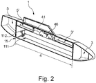
- FIG. 2 shows a sectional view of another embodiment of the multi-function pod 1.
- the pod 1 has a first tank area 3 in the front region of the pod 1, a so-called fore tank.
- the pod 1 has yet another tank area 5 in the rear area of the pod 1, a so-called aft tank.
- the first tank area 3 is connected to an additional tank area 3 ', on the side of the central area 4 of the pod 1 facing the aircraft.
- the further tank area 5 is connected to an additional tank area 5 ', on the side of the middle area 4 of the pod 1 facing the aircraft.
- the receiving device 41 for receiving holding devices or discharge devices 46 is arranged on the side of the central area 4 of the pod 1 facing the aircraft.
- the loading opening 11 of the loading area 4 can be closed with a closure device 11.
- the closure device 11 consists of a closure mechanism 112 and a closure flap 111.
- the closure flap 111 can be opened and the further load 42 (not shown) can be fastened to the holding device or ejection device 46.
- FIGS FIGS. 4 to 7 Various exemplary configurations of loading of the loading area 4 are shown in FIGS FIGS. 4 to 7 shown.
- FIG. 3 shows various embodiments of the positioning of ejectors 46.
- This shows the FIG. 3a a first configuration of the arrangement of a discharge device 46 in the receiving device 41 of the pod 1.
- the receiving device 41 has three slots in the illustrated embodiment of the pod 1, in which discharge devices 46 or holding devices (not shown) can be attached. By forming a slot or guide or rail, along the extension direction of the pod 1, can be arranged drop-off devices 46 and holding devices variable.
- another load not shown
- FIG. 3b illustrated positioning of the discharge devices 46 for example, two other loads (not shown) next to each other on the discharge devices 46 are releasably secured.
- FIG. 3a illustrated embodiment of advantage.
- FIG. 3b illustrated embodiment of advantage.
- 2 smaller loads can be attached next to each other.
- positions of the discharge devices 46 can be combined with each other.
- a centrally disposed discharge device 46 and two discharge devices 46 arranged next to one another can be arranged one behind the other in the receiving device 41.
- the possibility of Combinations here depends only on the number of slots and the width of the pod 1, as well as the length of the loading area 4 of the pod. 1
- FIG. 4 shows various views of an embodiment of the multi-function pod 1 with a rocket 44. This shows FIG. 4a a side view of the multi-function pod 1 in section. In FIG. 4b is a sectional view of the multifunction pod 1 off FIG. 4a shown transversely to the longitudinal axis of the pod 1.
- the multi-function pod 1 has as an additional load 42 in the further area 4 of the pod 1 a discharge device 46 with a rocket 44.
- the rocket 44 is releasably attached to a discharge device 46 in the illustrated embodiment.
- the discharge device 46 is attached to the receiving device 41 of the pod 1.
- the receiving device 41 is covered by the tank area 3 '.
- signals can be transmitted from the aircraft to the launching device 46 or to the missile 44 itself, or in the reverse direction from the launching device 46 or the rocket 44 to the aircraft.
- FIG. 5 shows various views of an embodiment of the multi-function pod 1 with a plurality of bombs 45.
- This shows FIG. 5a a side view of the multi-function pod 1 in section.
- FIG. 5b is a sectional view of the multifunction pod 1 off FIG. 5a shown transversely to the longitudinal axis of the pod 1.
- the multi-function pod 1 has in the illustrated embodiment as another load 42 in the wider area 4 of Pods 1 a dropping device 46 with multiple bombs 45 on.
- the bombs 45 are releasably secured in the illustrated embodiment to a common dropping device 46 for four bombs 45.
- the common discharge device 46 has in the illustrated embodiment, four positions at which bombs 45 can be attached.
- the common discharge device 46 is attached to the receiving device 41 of the pod 1. In the FIG. 5b the receiving device 41 is covered by the tank area 3 'of the pod 1. Via a wireless or wired signal connection (not shown), for example, signals can be transmitted from the aircraft to the discharge device 46 or to the bomb 45 itself or in the reverse direction from the discharge device 46 or the bomb 45 to the aircraft.
- bombs 45 are shown, which are detachably attached to the discharge device, depending on the size of the loading area 4 or depending on the size of the attached bombs and / or missiles, these in different combinations or numbers in the loading area 4 of the pod 1 are housed.
- FIG. 6 shows various views of an embodiment of the multi-function pod with a tank container 43 as another load 42.
- This shows FIG. 6a a side view of the multi-function pod 1 in section.
- FIG. 6b is a sectional view of the multifunction pod 1 off FIG. 6a shown transversely to the longitudinal axis of the pod 1.
- the multi-function pod 1 has a tank container 43 as a further load 42 in the wider area 4 of the pod 1.
- the tank container 43 is attached via a holding device 46 to the receiving device 41 of the pod 1.
- the holding device 46 has an adapter (not shown).
- the adapter includes, for example, a sealed port for the fuel line which can be connected to the fuel tank 43 to provide fuel communication between the fuel tank 43 and the support 46 and further to the aircraft.
- the aircraft may have a corresponding fuel pump.
- the tank container 43 may be provided with a fuel pump which pumps the fuel from the container 43 into the aircraft.
- fuel can be circulated internally and externally between the available tank containers, such as, for example, the tank container 43, the first tank area 3 and the second tank area 5.
- fuel from the aircraft's own or internal tank in the tank area 3, 5 of the pod 1 or in the tank container 43, or vice versa can be pumped for load balancing.
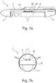
- FIG. 7 shows various views of an embodiment of the multi-function pod 1 with a sensor device 47 as another load.
- This shows Figure 7a a side view of the multi-function pod 1 in section.
- Figure 7b is a sectional view of the multifunction pod 1 off Figure 7a shown transversely to the longitudinal axis of the pod 1.
- the multi-function pod 1 has a sensor device 47 as a further load 42 in the wider area 4 of the pod 1.
- the sensor device 47 consists in the illustrated embodiment of a Container having, for example, a surveillance camera and electronic components for recording and controlling the surveillance camera, as well as for communicating the sensor device 47 with an aircraft or a ground station.
- the sensor device 47 is fastened to the receiving device 41 of the pod 1 via a holding device 46.
- the receiving device 41 is covered by the tank area 3 'of the pod 1.
- the holding device 46 is firmly connected to the sensor device 47, for example.
- the holding device 46 can be latched into the receiving device 41, for example.
- signals can be transmitted from the sensor device 47 to the aircraft or from the aircraft to the sensor device 47.
- the signals can be transmitted for example by cable and / or wireless from the sensor device 47 to the adapter and from the adapter to the aircraft, or from the aircraft to the sensor device 47.
Landscapes
- Engineering & Computer Science (AREA)
- Aviation & Aerospace Engineering (AREA)
- General Engineering & Computer Science (AREA)
- Tires In General (AREA)
- Filling Or Discharging Of Gas Storage Vessels (AREA)
- Details Of Aerials (AREA)
Description
- Verschiedene Ausführungsformen betreffen allgemein ein Flugzeug mit einem Multifunktions-Pod.
-
GB784429 - Moderne Flugzeuge, insbesondere Kampflugzeuge, weisen in der Regel nur eine begrenzte Zahl von Außenlastträgern zur Befestigung von Waffen oder Tankbehältern, sogenannten Pods, auf. Um die Reichweite eines Kampflugzeugs zu erhöhen sind beispielsweise zusätzliche Tankbehälter, sogenannte Abwurfstanks notwendig. Bei der Benutzung von Abwurfstanks steht folglich nur noch eine reduzierte Anzahl von Außenlastträgern für die Beladung des Flugzeugs mit anderen Lasten, wie beispielsweise Waffen zur Verfügung. Das Flugzeug kann somit weniger Lasten transportieren, oder die Reichweite des Flugzeugs ist auf die Reichweite eingeschränkt, die sich durch die Ausnutzung der im Flugzeug selbst angeordneten Tankbehälter erzielen lassen würde.
Davon ausgehend ist es Aufgabe der Erfindung, einen verbesserten Pod für ein Flugzeug zur Verfügung zu stellen, der die oben genannten Nachteile vermeidet. - Diese Aufgabe wird mit einem Flugzeug mit den Merkmalen des Anspruchs 1 gelöst. Beispielhafte Ausführungsformen sind in den abhängigen Ansprüchen dargestellt.
- Die Aufgabe wird durch ein Flugzeug mit einem Multifunktions-Pod gelöst. Der Multifunktions-Pod weist unter anderem mindestens zwei voneinander getrennte Bereiche auf. Mindestens ein erster Bereich des Pods ist zur Aufnahme von Treibstoff vorgesehen. Ein zweiter Bereich des Pods weist mindestens eine Aufnahmevorrichtung zur lösbaren Anbringung mindestens einer weiteren Last auf. Die weitere Last ist über eine an der dem Flugzeug abgewandten Seite des Pods aufweisende Ladeöffnung an der Aufnahmevorrichtung lösbar anbringbar.
- Der Erfindung liegt der Gedanke zugrunde, ein Flugzeug mit einem Multifunktions-Pod bereitzustellen, welcher sowohl einen Bereich für die Aufnahme von Treibstoff aufweist als auch wenigstens einen zweiten oder weiteren Bereich zur lösbaren Anbringung von einer weiteren Last aufweist. Der Multifunktions-Pod (oder auch nur Pod genannt) weist somit mehrere Funktionen auf, zum Einem die Funktion als externer Tankbehälter und zum Weiteren als Aufnahmebehälter für weitere lösbar angebrachte Lasten. Dadurch wird die für das Flugzeug zur Verfügung stehende Treibstoffmenge erhöht. Gleichzeitig wird die Anzahl der zur Verfügung stehenden Außenlastträger durch die im Pod zur Verfügung stehende Aufnahmevorrichtung beibehalten oder sogar erhöht.
Als Multifunktions-Pod oder Pod ist ein Aufnahmebehälter zu verstehen, der an einem Flugzeug, beispielsweise an der Unterseite des Rumpf oder der Unterseite der Tragflächen lösbar befestigt werden kann. Derartige Pods sind beispielsweise an Außenlastträgern des Flugzeugs befestigt und können während des Flugs von dem Flugzeug gelöst werden. Bei einer Verwendung als Behälter zur Aufnahme von Treibstoff werden diese beispielsweise auch als Abwurftank bezeichnet.
Der Pod weist eine, auf der dem Flugzeug abgewandten Seite, Ladeöffnung auf. Als dem Flugzeug abgewandt, ist die Seite zu verstehen, die bei einer Anbringung des Pods auf der Unterseite des Rumpfes oder der Tragfläche, von dem Flugzeug abgewandt ist, hier folglich auf der Unterseite des Pods. Bei einer Anbringung des Pods beispielsweise auf der Oberseite der Tragfläche kann die Ladeöffnung auf der dem Flugzeug abgewandten Seite somit auch beispielsweise, bei einer Normalposition des Flugzeugs auf der Oberseite des Pods sein. Beispielsweise kann bei einer Drehung des Flugzeugs im Flug die Ladeöffnung dann, beispielweise für das Lösen einer in dem zweiten Bereich angebrachten Last, nach unten gerichtet sein, so dass die Last abgeworfen werden kann. - Erfindungsgemäß sind über die Aufnahmevorrichtung unterschiedliche Arten von Lasten variabel in dem zweiten Bereich lösbar anbringbar. In dem zweiten Bereich des Pods sind über die Aufnahmevorrichtung unterschiedliche Art und Anzahl von Lasten lösbar anbringbar. Beispielsweise kann an der Aufnahmevorrichtung wenigstens ein Außenlastträger oder vergleichbarer Lastenträger oder Träger angebracht sein. Alternativ können auch mehrere, beispielsweise zwei oder mehrere Außenlastträger oder vergleichbare Lastenträger zur Aufnahme von mehreren weiteren Lasten parallel und/oder seriell in dem zweiten Bereich angeordnet sein. Dies hat den Vorteil, dass der Pod für unterschiedliche Art und Anzahl von Lasten nutzbar ist.
Bevorzugt ist die weitere Last mindestens ein Behälter zur Aufnahme von Treibstoff. Um die Reichweite des Flugzeugs weiter zu erhöhen kann beispielsweise in dem zweiten Bereich ein Behälter zur Aufnahme von Treibstoff angebracht werden. Dies hat den Vorteil, dass durch den Treibstoff aus dem ersten Bereich und dem Treibstoff aus dem zweiten Bereich des Pods die Reichweite des Flugzeugs wesentlich erhöht werden kann.
Bevorzugt weist die Aufnahmevorrichtung einen Adapter zur Entnahme von Treibstoff aus dem Behälter an das Flugzeug oder zur Befüllung des Behälters mit Treibstoff aus dem Flugzeug über eine externe Betankungsvorrichtung auf. Die Aufnahmevorrichtung kann beispielsweise mit einem Außenlastträger versehen werden, der einen Adapter aufweist über den eine Treibstoffverbindung zwischen dem Tankbehälter und dem Flugzeug hergestellt werden kann. Dies hat den Vorteil, dass über den Adapter Treibstoff aus dem Pod in das Flugzeug oder umgekehrt aus dem Flugzeug, beispielsweise bei einer Luftbetankung, in den Pod befördert werden kann. - Bevorzugt ist die weitere Last mindestens eine Rakete oder mindestens eine Bombe. Als Rakete ist beispielsweise ein Lenkflugkörper zu verstehen. Hierbei können die Raketen beispielsweise selbständig zielsuchende Raketen (fire and forget), ferngesteuerte Lenkflugkörper oder halbautomatische Lenkflugkörper sein. Als Bombe ist beispielsweise eine ungelenkte, dumme Bombe oder eine sogenannte präzisionsgelenkte Bombe (smart bomb) zu verstehen. Vorzugsweise sind die Raketen derart eingerichtet, dass diese nach dem Lösen von dem Pod eine kurze Strecke fallen, vorzugsweise wenigstens soweit, dass sie den Ladebereich des Pods verlassen haben, und erst nach dem Verlassen des Pods gezündet werden und in Richtung Ziel fliegen. Dies hat den Vorteil, dass das durch die weiteren Raketen oder Bomben die Verteidigungs- bzw. Angriffsmöglichkeiten des Flugzeugs erhöht werden können. Darüber hinaus bietet die Unterbringen von Raketen oder Bomben in dem Pod den Vorteil, dass von außen nicht erkennbar ist, ob und wie das Flugzeug bewaffnet ist, oder wie sich die Reichweitenerhöhung darstellt.
- Bevorzugt weist die Aufnahmevorrichtung mindestens eine Abwurfvorrichtung für eine oder mehrere Raketen auf. Mittels der wenigstens einen Abwurfvorrichtung, beispielsweise ein HDERU (Heavy Duty Ejector Release Unit) oder eine vergleichbare Haltevorrichtung, können eine oder mehrere Raketen lösbar befestigt werden, die beispielsweise bei Erreichen des Zielgebiets freigegeben werden können. Dies hat den Vorteil, dass der Pod neben dem transportierten Treibstoff auch mindestens eine Rakete zur Erhöhung der Verteidigungs- bzw. Angriffsmöglichkeiten des Flugzeugs befördern kann. Die wenigstens eine Abwurfvorrichtung ist vorzugsweise variabel an der Aufnahmevorrichtung anbringbar. Dies hat den Vorteil, dass beispielsweise die Position der Abwurfvorrichtung in Längsrichtung oder Querrichtung des Pods passend zu der jeweiligen anzubringenden Last oder der Anzahl der Lasten verändert werden kann.
- Bevorzugt weist die Aufnahmevorrichtung mindestens eine Abwurfvorrichtung für eine oder mehrere Bomben auf. Mittels der wenigstens einen Abwurfvorrichtung, beispielsweise ein HDERU (Heavy Duty Ejector Release Unit), können eine oder mehrere Bomben lösbar befestigt werden, die beispielsweise bei Erreichen des Zielgebiets freigegeben werden können. Dies hat den Vorteil, dass der Pod neben dem transportierten Treibstoff auch mindestens eine Bombe zur Erhöhung der Verteidigungs- bzw. Angriffsmöglichkeiten des Flugzeugs befördern kann. Die wenigstens eine Abwurfvorrichtung oder Haltevorrichtung ist vorzugsweise variabel an der Aufnahmevorrichtung anbringbar. Dies hat den Vorteil, dass beispielsweise die Position und/oder die Anzahl der Abwurfvorrichtung in Längsrichtung oder Querrichtung des Pods, passend zu der jeweiligen anzubringenden Last oder der Anzahl der Lasten bzw. der Bomben, verändert werden kann.
- Bevorzugt weist die Aufnahmevorrichtung mindestens einen Adapter zur Steuerung des Abwurfs der Raketen oder Bomben über das Flugzeug auf. Um die Rakete/Raketen und/oder die Bombe/Bomben beispielsweise wie gewünscht in der Nähe des Zielgebiets freizugeben, weist die Aufnahmevorrichtung mindestens einen Adapter auf, der vorzugsweise mit einer Freigabevorrichtung beispielsweise im Cockpit des Flugzeugs verbunden ist und über den Signale an die Abwurfvorrichtung übermittelt werden können, bzw. von dieser beispielsweise an das Cockpit übermittelt werden können. Über den Adapter kann beispielsweise ein Signal an die Abwurfvorrichtung übermittelt werden, damit die Abwurfvorrichtung ein Rakete oder Bombe freigibt. Dies hat den Vorteil, dass über den Adapter beispielsweise weitere Informationen, beispielsweise aus dem Cockpit an eine selbständig zielsuchende Rakete oder eine präzisionsgelenkte Bombe, beispielsweise Zielkoordinaten, übermittelt werden können oder Statusinformationen der Rakete oder Bombe an einen Bordcomputer im Flugzeug oder an das Cockpit übermittelt werden können.
- Bevorzugt sind mehrere Raketen und/oder Bomben parallel und/oder hintereinander an der Aufnahmevorrichtung lösbar anbringbar. Beispielsweise können an der Aufnahmevorrichtung mehrere Abwurfvorrichtungen, beispielsweise HDERUs angeordnet sein. Hierbei können beispielsweise zwei oder mehrere HDERUs seriell, d.h. in Längsrichtung des Pods hintereinander innerhalb des Ladebereichs, angeordnet sein. Weiter können beispielsweise zwei oder mehrere HDERUs nebeneinander an der Aufnahmevorrichtung angeordnet sein. Beispielsweise können auch zwei HDERUs parallel für die Aufnahme von beispielsweise zwei kleineren Raketen oder Bomben angeordnet sein und seriell dazu ein einzelne HDERU für die Aufnahme einer größeren Rakete oder Bombe. Dies hat den Vorteil, dass durch eine Aufnahmevorrichtung die eine nahezu unbegrenzte Variabilität hinsichtlich der Anbringung der Abwurfvorrichtungen aufweist, nahezu beliebige Raketen oder Bomben oder Kombinationen von Raketen und/oder Bomben in dem Ladebereich des Pods lösbar angebracht werden können. Die Anzahl bzw. Anordnung ist lediglich durch die Größe des Ladebereichs des Pods begrenzt.
- Bevorzugt ist die weitere Last mindestens eine Sensorvorrichtung. Beispielsweise ist die weitere Last eine Sensorvorrichtung zur Aufklärung und/oder Überwachung eines Fluggebiets oder eines Territoriums. Alternativ kann die weitere Last auch ein Kommunikationsmodul beispielsweise zur Kommunikation des Flugzeugs mit weiteren Flugzeugen sein. Darüber hinaus kann auch die Sensorvorrichtung weitere eine Kommunikationsvorrichtung aufweisen. Dies hat den Vorteil, dass das Flugzeug über den Pod neben der Beförderung von Treibstoff weitere Fähigkeiten beispielsweise zur Aufklärung und/oder Überwachung aufweisen kann. Darüber hinaus hat dies den Vorteil, dass von außen nicht erkennbar bzw. nur sehr schwer erkennbar ist, ob eine Flugmission mit einem Sensor durchgeführt wird oder nicht.
- Bevorzugt weist die Aufnahmevorrichtung mindestens einen Adapter zur Kommunikation des Flugzeuges mit der Sensoreinrichtung auf. Um Daten mit der Sensorvorrichtung auszutauschen, d.h. in Richtung vom Flugzeug zu der Sensorvorrichtung oder von der Sensorvorrichtung zu dem Flugzeug, weist die Aufnahmevorrichtung einen Adapter auf, der mit der Sensorvorrichtung verbindbar oder koppelbar ist. Der Adapter kann beispielsweise einen kabelgebundenen und/oder einen kabellosen Datenaustausch zwischen der Sensorvorrichtung und dem Flugzeug ermöglichen. Bei einer kabelgebundenen Ausführungsform ist beispielsweise die Aufnahmevorrichtung mit einer Buchse versehen, in die ein Stecker eines Kabels, das mit der Sensorvorrichtung verbunden ist, gekoppelt werden kann. Die Buchse der Aufnahmevorrichtung ist beispielsweise mit dem Flugzeug über beispielsweise eine weitere kabelgebundene und/oder auch kabellose Verbindung verbunden. Dies hat den Vorteil, dass über den Pod neben der Beförderung von Treibstoff und "dummen" Lasten auch Lasten transportiert werden können, die einen Datenaustausch zu oder mit dem Flugzeug aufweisen.
- Erfindungsgemäß weist der Pod wenigstens einen weiteren Bereich zur Aufnahme von Treibstoff auf. Bevorzugt weist der Pod zusätzlich zu dem ersten Bereich zum Transport von Treibstoff wenigstens einen oder auch mehrere weitere Bereich auf, in denen Treibstoff aufgenommen werden kann. Dies hat den Vorteil, dass die im Pod mitgeführte Treibstoffmenge erhöht ist.
- Erfindungsgemäß sind die Bereiche des Pods zur Aufnahme von Treibstoff im vorderen und hinteren Bereich des Pods angeordnet. Beispielsweise sind der vordere und der hintere Bereich des Pods als Treibstoffbereich vorgesehen. Der vordere und hintere Bereich eines Pods weisen beispielsweise aus aerodynamischen Gründen eine konisch zulaufende Form auf, wobei der Zwischenbereich zumindest teilweise oder auch größtenteils eine möglichst gleichbleibende Außenkontur aufweist. Zur Aufnahme einer weiteren Last im Ladebereich kann es von Vorteil sein, wenn der Ladebereich beispielsweise in dem Bereich mit einer möglichst gleichbleibenden Außenkontur vorgesehen ist. Zur bestmöglichen Ausnutzung des Pods ist der Bereich mit einer zulaufenden Form oder mit einer nicht konstanten Außenform für die Aufnahme von Treibstoff vorgesehen, da die Form des Pods in dem Bereich für die Aufnahme von Treibstoff nahezu unerheblich ist. Für die Aufnahme von weiteren Lasten ist ein Ladebereich mit einer gleichbleibenden Form von Vorteil. Dies hat den Vorteil, dass sich dadurch nahezu der gesamte Ladebereich variabel für die Aufnahme von Lasten nutzen lässt. Weiter hat dies den Vorteil, dass neben der Beförderung einer oder mehrere weiterer Lasten, das zur Verfügung stehende Volumen des Pods für die weitere Aufnahme von Treibstoff möglichst optimal ausgenutzt werden kann. Darüber hinaus besteht der Vorteil, dass unabhängig von der Beladung im Lastbereich des Pods die Außengeometrie des Pods immer gleich ist. Dies erleichtert zudem die Flugzeug-Regelung durch das Flug-Kontroll-System des Flugzeugs.
Um eine möglichst gleichbleibende Lastverteilung des Pods zu erreichen können die Bereiche für die Aufnahme von Treibstoff möglichst Schwerpunktneutral verteilt angeordnet sein. Um eine möglichst optimale Schwerpunktsverteilung zu erreichen können darüber hinaus beispielsweise die Bereiche zur Aufnahme von Treibstoff im vorderen Bereich und im hinteren Bereich des Pods möglichst gleichgroß sein. Dies hat den Vorteil, dass bei einer gleichmäßigen Treibstoffaufnahme bzw. Treibstoffentnahme während des Flugs der Pod weiterhin möglichst im Gleichgewicht ist. Ein Umpumpen von Treibstoff zum Lastausgleich kann somit zumindest innerhalb des Pods selbst vermieden werden. Für den Lastausgleich des gesamten Flugzeugs kann es jedoch von Vorteil sein, wenn Treibstoff zwischen den verfügbaren Tankbehältern, intern und extern umgepumpt werden kann. Beispielsweise kann auch Treibstoff aus dem Flugzeugeigenen Tank in den Tankbereich des Pods zum Lastausgleich umgepumpt werden oder umgekehrt. - Der Bereich zur Aufnahme der weiteren Last ist erfindungsgemäß zwischen den Bereichen zur Aufnahme von Treibstoff angeordnet. Beispielweise ist der Bereich zur Aufnahme des Treibstoffs in zwei oder mehrere Unterbereiche oder Segmente unterteilt. Der Bereich zur Aufnahme der weiteren Last ist beispielsweise wenigstens teilweise zwischen den Bereichen für den Treibstoff angeordnet. Beispielsweise sind der vordere und der hintere Bereich des Pods als Treibstoffbereich vorgesehen und ein Zwischenbereich ist als Ladebereich zur Aufnahme einer weiteren Last vorgesehen. Hierbei können sich die Bereiche für den Treibstoff auch wenigstens teilweise in den Ladebereich erstrecken. Dies hat den Vorteil, dass das zur Verfügung stehende Volumen des Pods optimal ausgenutzt werden kann.
- Erfindungsgemäß erstrecken sich die Bereiche zur Aufnahme von Treibstoff, auf der dem Flugzeug zugewandten Seite des Pods, zumindest teilweise in den zweiten Bereich. Der Multifunktions-Pod kann beispielsweise im Bereich der Aufnahmevorrichtung weitere Bereiche zur Aufnahme von Treibstoff aufweisen. Diese weiteren Tankbereiche sind beispielsweise oberhalb des zweiten Bereichs, d.h. des Ladebereichs, angeordnet. Über die Ladeöffnung kann auf der Unterseite der Ladebereich bestückt werden. Der erste Bereich zur Aufnahme von Treibstoff ist beispielsweise direkt mit dem weiteren Bereich zur Aufnahme von Treibstoff verbunden. Beispielsweise kann sich der erste Bereich über den weiteren Bereich in der Art erstrecken, dass ein gemeinsamer Tankbehälter vorliegt. Alternativ können zwei getrennte Tankbereiche vorgesehen sein, wobei einer der beiden als eigentlicher Tankbehälter oder Haupttank vorgesehen ist und der weitere als Ausgleichstank oder Zwischentank vorgesehen. Dies hat den Vorteil, dass das zur Verfügung stehende Volumen des Pods optimal ausgenutzt werden kann. Hierbei kann beispielsweise der Treibstoff über den Ausgleichs- bzw. Zwischentank aus dem eigentlichen Tankbehälter in das Flugzeug gepumpt, d.h. in dem Tankbehälter ist eine Pumpe angeordnet, die den Treibstoff aus dem Pod in das Flugzeug pumpt, oder gesaugt werden, d.h. in dem Flugzeug ist eine Pumpe angeordnet, die den Treibstoff aus dem Pod in das Flugzeug befördert.
- Bevorzugt ist die Ladeöffnung mit mindestens einer Verschlussvorrichtung verschließbar. Die Verschlussvorrichtung kann beispielsweise einer oder mehreren, symmetrischen oder asymmetrischen Klappen, Jalousien, oder dergleichen aufweisen. Zur Betätigung der Verschlussvorrichtung ist vorzugsweise eine entsprechende Mechanik vorgesehen, die beispielsweise die Klappen bei Bedarf öffnen bzw. schließen kann Die Verschlussvorrichtung verschließt die Ladeöffnung nach außen. Bevorzugt ist die Verschlussvorrichtung aerodynamisch an die Außenkontur des Pods im Bereich der Ladeöffnung angepasst. Um die weitere Last oder die mehreren Lasten in dem Ladebereich über die Ladeöffnung anzubringen wir die Verschlussvorrichtung geöffnet. Während des Flugs ist die Ladeöffnung durch die Verschlussvorrichtung die meiste Zeit verschlossen. Zum Abwerfen von Lasten während des Flugs kann die Verschlussvorrichtung während des Flugs geöffnet werden und die Ladeöffnung freigeben. Dies hat den Vorteil, dass der Pod im Ladebereich eine möglichst aerodynamisch günstige Außenkontur aufweist. Darüber hinaus bietet die aerodynamische Verkleidung eine Optimierung der Aerodynamik des Flugzeugs, wodurch eine Reichweiten-Erhöhung bei gleicher Flugzeug-Beladung möglich ist. Zudem werden die Stealth-Eigenschaften des Flugzeugs bei gleicher Beladung durch den Einsatz des Pods verbessert.
- In den Zeichnungen beziehen sich im Allgemeinen gleiche Bezugszeichen auf die gleichen Teile über die verschiedenen Ansichten hinweg. Die Zeichnungen sind nicht notwendigerweise maßstabsgetreu; Wert wird stattdessen im Allgemeinen auf die Veranschaulichung der Prinzipien der Erfindung gelegt. In der folgenden Beschreibung werden verschiedene Ausführungsformen der Erfindung beschrieben unter Bezugnahme auf die folgenden Zeichnungen, in denen:
- FIG. 1
- verschiedene Ansichten einer ersten Ausführungsform des Multifunktions-Pods zeigt;
- FIG. 2
- eine Schnittdarstellung einer weiteren Ausführungsform des Multifunktions-Pods zeigt;
- FIG. 3
- verschiedene Ausführungsformen der Positionierung von Abwurfvorrichtungen zeigt;
- FIG. 4
- verschiedene Ansichten einer Ausführungsform des Multifunktions-Pods mit einer Rakete zeigt;
- FIG. 5
- verschiedene Ansichten einer Ausführungsform des Multifunktions-Pods mit einer Mehrzahl Bomben zeigt;
- FIG. 6
- verschiedene Ansichten einer Ausführungsform des Multifunktions-Pods mit einem Tankbehälter als weitere Last zeigt; und
- Fig. 7
- verschiedene Ansichten einer Ausführungsform des Multifunktions-Pods mit einer Sensorvorrichtung als weitere Last zeigt.
- Die folgende detaillierte Beschreibung nimmt Bezug auf die beigefügten Zeichnungen, welche zur Erläuterung spezifische Details und Ausführungsformen zeigen, in welchem die Erfindung praktiziert werden kann.
- Das Wort "beispielhaft" wird hierin verwendet mit der Bedeutung "als ein Beispiel, Fall oder Veranschaulichung dienend". Jede Ausführungsform oder Ausgestaltung, die hierin als "beispielhaft" beschrieben ist, ist nicht notwendigerweise als bevorzugt oder vorteilhaft gegenüber anderen Ausführungsformen oder Ausgestaltungen auszulegen.
- In der folgenden ausführlichen Beschreibung wird auf die beigefügten Zeichnungen Bezug genommen, die Teil dieser bilden und in denen zur Veranschaulichung spezifische Ausführungsformen gezeigt sind, in denen die Erfindung ausgeübt werden kann. In dieser Hinsicht wird Richtungsterminologie wie etwa "oben", "unten", "vorne", "hinten", "vorderes", "hinteres", usw. mit Bezug auf die Orientierung der beschriebenen Figur(en) verwendet. Da Komponenten von Ausführungsformen in einer Anzahl verschiedener Orientierungen positioniert werden können, dient die Richtungsterminologie zur Veranschaulichung und ist auf keinerlei Weise einschränkend. Es versteht sich, dass andere Ausführungsformen benutzt und strukturelle oder logische Änderungen vorgenommen werden können, ohne von dem Schutzumfang der vorliegenden Erfindung abzuweichen. Es versteht sich, dass die Merkmale der hierin beschriebenen verschiedenen beispielhaften Ausführungsformen miteinander kombiniert werden können, sofern nicht spezifisch anders angegeben. Die folgende ausführliche Beschreibung ist deshalb nicht in einschränkendem Sinne aufzufassen, und der Schutzumfang der vorliegenden Erfindung wird durch die angefügten Ansprüche definiert.
- Im Rahmen dieser Beschreibung werden die Begriffe "verbunden", "angeschlossen" sowie "gekoppelt" verwendet zum Beschreiben sowohl einer direkten als auch einer indirekten Verbindung, eines direkten oder indirekten Anschlusses sowie einer direkten oder indirekten Kopplung. In den Figuren werden identische oder ähnliche Elemente mit identischen Bezugszeichen versehen, soweit dies zweckmäßig ist.
-
Figur 1 zeigt verschiedene Ansichten einer ersten Ausführungsform des Multifunktions-Pods 1. Hierbei ist ein Multifunktions-Pod inFigur 1a in einer Schnittdarstellung dargestellt und inFigur 1b in einer dreidimensionalen Ansicht. - Der Multifunktions-Pod 1 weist in der dargestellten Ausführungsform einen ersten Bereich 3 zur Aufnahme von Treibstoff und einen weiteren Bereich 4 zur Aufnahme einer weiteren Last 42 auf. Der weitere Bereich 4 dient als Ladebereich für die Aufnahme von unterschiedlichen Arten von Lasten. Die weitere Last 42 kann über eine Ladeöffnung 11 auf der Unterseite, d.h. der dem Flugzeug abgewandten Seite des Pods 1, in den Ladebereich 4 eingebracht werden. In dem Ladebereich 4 kann die weitere Last 42 an einer Aufnahmevorrichtung 41 variabel befestigt werden. Wie in
Figur 1b zu erkennen ist, erstreckt sich die Aufnahmevorrichtung 41 über einen Teilbereich des Ladebereichs 4 an dem oberen, dem Flugzeug zugewandten Wandabschnitt des Pods 1. Die Aufnahmevorrichtung 41 kann sich in einer weiteren nicht dargestellten Ausführungsform des Pods 1 auch über die gesamte Länge des Ladebereichs 4 erstrecken. Zur lösbaren Befestigung der weiteren Last 42 an der Aufnahmevorrichtung 41 kann beispielsweise eine odere mehrere Abwurfvorrichtungen oder Haltevorrichtungen, wie beispielsweise eine HDERU (Heavy Duty Ejector Release Unit), variabel an der Aufnahmevorrichtung 41 angebracht werden. In der dargestellten Ausführungsform weist die Aufnahmevorrichtung 41 mehrere nebeneinander liegende Schlitze oder Führungen bzw. Schienen auf, in denen beispielsweise Abwurfvorrichtungen oder Haltevorrichtungen befestigt werden können. Durch die Ausführung als Schlitz oder Führung bzw. Schiene können die Abwurfvorrichtungen oder Haltevorrichtungen in Längsrichtung der Schlitze oder Führungen bzw. Schienen, d.h. in der hier dargestellten Ausführungsform in Längsrichtung des Pods 1 variabel befestigt werden. Eine Detailansicht der Aufnahmevorrichtung 41 ist inFigur 3 dargestellt. In der dargestellten Ausführungsform weist der Pod 1 in den Seitenwänden im Bereich des Ladebereichs 4 zusätzlich Wartungsöffnungen 13 auf. Über die Wartungsöffnungen 13 besteht beispielsweise ein Zugang zu der Haltevorrichtung bzw. Abwurfvorrichtung in der Aufnahmevorrichtung 41. -
Figur 2 zeigt eine Schnittdarstellung einer weiteren Ausführungsform des Multifunktions-Pods 1. Der Pod 1 weist einen ersten Tankbereich 3 im vorderen Bereich des Pods 1, einen sogenannten fore Tank auf. Zusätzlich weist der Pod 1 noch einen weiteren Tankbereich 5 im rückwärtigen Bereich des Pods 1 auf, einen sogenannten aft Tank. Der erste Tankbereich 3 ist mit einem zusätzlichen Tankbereich 3', auf der dem Flugzeug zugewandten Seite des mittleren Bereichs 4 des Pods 1, verbunden. Ebenso ist der weitere Tankbereich 5 mit einem zusätzlichen Tankbereich 5', auf der dem Flugzeug zugewandten Seite des mittleren Bereichs 4 des Pods 1, verbunden. Zwischen den beiden zusätzlichen Tankbereichen 3' und 5' ist die Aufnahmevorrichtung 41 zur Aufnahme von Haltevorrichtungen bzw. Abwurfvorrichtungen 46 auf der dem Flugzeug zugewandten Seite des mittleren Bereichs 4 des Pods 1 angeordnet. Die Ladeöffnung 11 des Ladebereichs 4 ist mit einer Verschlussvorrichtung 11 verschließbar. Die Verschlussvorrichtung 11 besteht in der dargestellten Ausführungsform aus einem Verschlussmechanismus 112 und eines Verschlussklappe 111. Zum Bestücken des Ladebereichs 4 kann die Verschlussklappe 111 geöffnet werden und die weitere Last 42 (nicht dargestellt) kann an der Haltevorrichtung bzw. Abwurfvorrichtung 46 befestigt werden. Verschiedene beispielhafte Konfigurationen der Beladung des Ladebereichs 4 sind in denFiguren 4 bis 7 dargestellt. -
Figur 3 zeigt verschiedene Ausführungsformen der Positionierung von Abwurfvorrichtungen 46. Hierbei zeigt dieFigur 3a eine erste Konfiguration der Anordnung einer Abwurfvorrichtung 46 in der Aufnahmevorrichtung 41 des Pods 1. Die Aufnahmevorrichtung 41 weist in der dargestellten Ausführungsform des Pods 1 drei Schlitze auf, in denen Abwurfvorrichtungen 46 oder Haltevorrichtungen (nicht dargestellt) befestigt werden können. Durch die Ausbildung als Schlitz oder Führung bzw. Schiene, längs zur Erstreckungsrichtung des Pods 1, lassen sich Abwurfvorrichtungen 46 bzw. Haltevorrichtungen variabel anordnen. Bei der in derFigur 3a dargestellten Positionierung der Abwurfvorrichtung 46 kann beispielsweise eine weitere Last (nicht dargestellt) an der Abwurfvorrichtung 46 befestigt werden. Bei der inFigur 3b dargestellten Positionierung der Abwurfvorrichtungen 46 können beispielsweise zwei weitere Lasten (nicht dargestellt) nebeneinander an den Abwurfvorrichtungen 46 lösbar befestigt werden. Besteht beispielsweise der Bedarf, eine hinsichtlich der Abmessungen größere Last an der Abwurfvorrichtung 46 zu befestigen, ist die inFigur 3a dargestellte Ausführungsform von Vorteil. Bei der Befestigung von zwei kleineren Lasten ist beispielsweise die inFigur 3b dargestellte Ausführungsform von Vorteil. Hier können 2 kleinere Lasten nebeneinander befestigt werden. Die inFigur 3a und Figur 3b dargestellten Positionierungen der Abwurfvorrichtungen 46 können beliebig miteinander kombiniert werden. Dadurch können beispielsweise, je nach Bedarf, eine mittig angeordnete Abwurfvorrichtung 46 und zwei nebeneinander angeordnete Abwurfvorrichtungen 46 hintereinander in der Aufnahmevorrichtung 41 angeordnet werden. Die Möglichkeit der Kombinationen ist hierbei nur abhängig von der Anzahl der Schlitze und der Breite des Pods 1, sowie der Länge des Ladebereichs 4 des Pods 1. -
Figur 4 zeigt verschiedene Ansichten einer Ausführungsform des Multifunktions-Pods 1 mit einer Rakete 44. Hierbei zeigtFigur 4a eine Seitenansicht des Multifunktions-Pods 1 in Schnittdarstellung. InFigur 4b ist eine Schnittdarstellung des Multifunktions-Pods 1 ausFigur 4a quer zur Längsachse des Pods 1 dargestellt. - Der Multifunktions-Pod 1 weist in der dargestellten Ausführungsform als weitere Last 42 im weiteren Bereich 4 des Pods 1 eine Abwurfvorrichtung 46 mit einer Rakete 44 auf. Die Rakete 44 ist in der dargestellten Ausführungsform an einer Abwurfvorrichtung 46 lösbar befestigt. Die Abwurfvorrichtung 46 ist an der Aufnahmevorrichtung 41 des Pods 1 angebracht. In der
Figur 4b ist die Aufnahmevorrichtung 41 durch den Tankbereich 3' verdeckt. Über eine kabellose oder kabelgebundene Signalverbindung (nicht dargestellt) können beispielsweise Signale von dem Flugzeug an die Abwurfvorrichtung 46 bzw. an die Rakete 44 selbst übermittelt werden, oder in umgekehrter Richtung von der Abwurfvorrichtung 46 bzw. der Rakete 44 an das Flugzeug. -
Figur 5 zeigt verschiedene Ansichten einer Ausführungsform des Multifunktions-Pods 1 mit einer Mehrzahl Bomben 45. Hierbei zeigtFigur 5a eine Seitenansicht des Multifunktions-Pods 1 in Schnittdarstellung. InFigur 5b ist eine Schnittdarstellung des Multifunktions-Pods 1 ausFigur 5a quer zur Längsachse des Pods 1 dargestellt. - Der Multifunktions-Pod 1 weist in der dargestellten Ausführungsform als weitere Last 42 im weiteren Bereich 4 des Pods 1 eine Abwurfvorrichtung 46 mit mehreren Bomben 45 auf. Die Bomben 45 sind in der dargestellten Ausführungsform an einer gemeinsamen Abwurfvorrichtung 46 für vier Bomben 45 lösbar befestigt. Die gemeinsame Abwurfvorrichtung 46 weist in der dargestellten Ausführungsform vier Positionen auf, an denen Bomben 45 befestigt werden können. Die gemeinsame Abwurfvorrichtung 46 ist an der Aufnahmevorrichtung 41 des Pods 1 angebracht. In der
Figur 5b ist die Aufnahmevorrichtung 41 durch den Tankbereich 3' des Pods 1 verdeckt. Über eine kabellose oder kabelgebundene Signalverbindung (nicht dargestellt) können beispielsweise Signale von dem Flugzeug an die Abwurfvorrichtung 46 bzw. an die Bombe 45 selbst übermittelt werden oder in umgekehrter Richtung von der Abwurfvorrichtung 46 bzw. der Bombe 45 an das Flugzeug. Obwohl in der dargestellten Ausführungsform nur vier Bomben 45 dargestellt sind, die an der Abwurfvorrichtung lösbar angebracht sind, können abhängig von der Größe des Ladebereichs 4 bzw. abhängig von der Größe der angebrachten Bomben und/oder Raketen, diese in unterschiedlicher Kombination bzw. Anzahl im dem Ladebereich 4 des Pods 1 untergebracht werden. -
Figur 6 zeigt verschiedene Ansichten einer Ausführungsform des Multifunktions-Pods mit einem Tankbehälter 43 als weitere Last 42. Hierbei zeigtFigur 6a eine Seitenansicht des Multifunktions-Pods 1 in Schnittdarstellung. InFigur 6b ist eine Schnittdarstellung des Multifunktions-Pods 1 ausFigur 6a quer zur Längsachse des Pods 1 dargestellt. - Der Multifunktions-Pod 1 weist in der dargestellten Ausführungsform als weitere Last 42 im weiteren Bereich 4 des Pods 1 einen Tankbehälter 43 auf. Der Tankbehälter 43 ist über eine Haltevorrichtung 46 an der Aufnahmevorrichtung 41 des Pods 1 befestigt. In der
Figur 6b ist die Aufnahmevorrichtung 41 durch den Tankbereich 3' des Pods 1 verdeckt. Um den Treibstoff aus dem Tankbehälter 43 in das Flugzeug zu befördern weist die Haltevorrichtung 46 einen Adapter (nicht dargestellt) auf. Der Adapter weist beispielsweise einen abgedichteten Anschluss für die Treibstoffleitung auf der mit dem Treibstoffbehälter 43 verbunden werden kann um die Treibstoffverbindung zwischen dem Treibstoffbehälter 43 und der Haltevorrichtung 46 und weiter zu dem Flugzeug zu bereitzustellen. Zur Beförderung des Treibstoffs aus dem Tankbehälter 43 in das Flugzeug kann beispielsweise das Flugzeug eine entsprechende Treibstoffpumpe aufweisen. Alternativ kann auch der Tankbehälter 43 mit einer Treibstoffpumpe versehen sein, die den Treibstoff aus dem Behälter 43 in das Flugzeug pumpt. Für den Lastausgleich des gesamten Flugzeugs kann es jedoch von Vorteil sein, wenn Treibstoff zwischen den verfügbaren Tankbehältern, wie beispielsweise dem Tankbehälter 43, dem ersten Tankbereich 3 und dem zweiten Tankbereich 5, intern und extern umgepumpt werden kann. Beispielsweise kann auch Treibstoff aus dem Flugzeugeigenen bzw. internen Tank in den Tankbereich 3, 5 des Pods 1 oder in den Tankbehälter 43, oder umgekehrt, zum Lastausgleich umgepumpt werden. -
Figur 7 zeigt verschiedene Ansichten einer Ausführungsform des Multifunktions-Pods 1 mit einer Sensorvorrichtung 47 als weitere Last. Hierbei zeigtFigur 7a eine Seitenansicht des Multifunktions-Pods 1 in Schnittdarstellung. InFigur 7b ist eine Schnittdarstellung des Multifunktions-Pods 1 ausFigur 7a quer zur Längsachse des Pods 1 dargestellt. - Der Multifunktions-Pod 1 weist in der dargestellten Ausführungsform als weitere Last 42 im weiteren Bereich 4 des Pods 1 eine Sensorvorrichtung 47 auf. Die Sensorvorrichtung 47 besteht in der dargestellten Ausführungsform aus einem Behälter, der beispielsweise eine Überwachungskamera und elektronische Komponenten zur Aufzeichnung und Steuerung der Überwachungskamera, sowie zur Kommunikation der Sensorvorrichtung 47 mit einem Flugzeug oder einer Bodenstation aufweist. Die Sensorvorrichtung 47 ist über eine Haltevorrichtung 46 an der Aufnahmevorrichtung 41 des Pods 1 befestigt. In der
Figur 7b ist die Aufnahmevorrichtung 41 durch den Tankbereich 3' des Pods 1 verdeckt. Die Haltevorrichtung 46 ist beispielweise mit der Sensorvorrichtung 47 fest verbunden. Die Haltevorrichtung 46 kann zur Aufnahme der Sensorvorrichtung 47 in dem Ladebereich 4 des Pods 1 in die Aufnahmevorrichtung 41, beispielsweise eingerastet werden. Über einen Adapter (nicht dargestellt) können beispielsweise Signale von der Sensorvorrichtung 47 an das Flugzeug oder von dem Flugzeug an die Sensorvorrichtung 47 übertragen werden. Die Signale können beispielsweise kabelgebunden und/oder kabellos von der Sensorvorrichtung 47 an den Adapter und von dem Adapter an das Flugzeug übertragen werden, bzw. von dem Flugzeug an die Sensorvorrichtung 47. Obwohl die Erfindung vor allem unter Bezugnahme auf bestimmte Ausführungsformen gezeigt und beschrieben worden ist, sollte von denjenigen, die mit dem Fachgebiet vertraut sind, verstanden werden, dass zahlreiche Änderungen bezüglich Ausgestaltung und Details daran vorgenommen werden können, ohne vom Bereich der Erfindung, wie durch die angefügten Ansprüche definiert, abzuweichen. Der Bereich der Erfindung wird somit durch die angefügten Ansprüche bestimmt, und es ist daher beabsichtigt, dass sämtliche Änderungen, welche unter den Wortsinn oder den Äquivalenzbereich der Ansprüche fallen, umfasst werden. -
- 1
- Pod
- 3, 3'
- erster Bereich
- 4
- zweiter Bereich
- 41
- Aufnahmevorrichtung
- 411
- Adapter
- 42
- weitere Last
- 43
- Treibstoffbehälter
- 44
- Rakete
- 45
- Bombe
- 46
- Abwurfvorrichtung
- 47
- Sensorvorrichtung
- 5, 5'
- weiterer Bereich
- 11
- Ladeöffnung
- 12
- Verschlussvorrichtung
- 13
- Wartungsöffnung
Claims (12)
- Flugzeug, mit einem an dem Flugzeug lösbar befestigten Multifunktions-Pod (1),
wobei der Pod (1) mindestens zwei voneinander getrennte Bereiche (3, 4) aufweist;
wobei mindestens ein erster Bereich (3) des Pods (1) zur Aufnahme von Treibstoff vorgesehen ist, wobei der erste Bereich (3) des Pods (1) zur Aufnahme von Treibstoff im vorderen Bereich des Pods (1) angeordnet ist;
wobei ein zweiter Bereich (4) des Pods (1) mindestens eine Aufnahmevorrichtung (41) zur lösbaren Anbringung mindestens einer weiteren Last (42) aufweist;
wobei die weitere Last (42) über eine an der dem Flugzeug abgewandten Seite des Pods (1) aufweisende Ladeöffnung (11) an der Aufnahmevorrichtung (41) lösbar anbringbar ist, wobei ein dritter Bereich (5) des Pods (1) zur Aufnahme von Treibstoff vorgesehen ist, wobei der dritte Bereich (5) des Pods (1) im rückwärtigen Bereich des Pods (1) angeordnet ist,
wobei der zweite Bereich (4) in Längsrichtung des Pods (1) zwischen dem ersten Bereich (3) und dem dritten Bereich (5) angeordnet ist,
wobei der Multifunktions-Pod (1) während eines Flugs des Flugzeugs von diesem lösbar ist, dadurch gekennzeichnet, dass sich die Bereiche (3, 5) zur Aufnahme von Treibstoff, auf der dem Flugzeug zugewandten Seite des Pods, zumindest teilweise in den zweiten Bereich (4) erstrecken, und wobei die Aufnahmevorrichtung (41) zwischen den sich zumindest teilweise in den zweiten Bereich (4) erstreckenden Bereichen (3, 5) zur Aufnahme von Treibstoff angeordnet ist. - Flugzeug gemäß Anspruch 1,
wobei über die Aufnahmevorrichtung (41) unterschiedliche Arten von Lasten (42) variabel in dem zweiten Bereich (4) lösbar anbringbar sind. - Flugzeug nach einem der vorherstehenden Ansprüche,
wobei die weitere Last (42) mindestens ein Behälter (43) zur Aufnahme von Treibstoff ist. - Flugzeug nach Anspruch 3,
wobei die Aufnahmevorrichtung (41) mindestens einen Adapter zur Entnahme von Treibstoff aus dem Behälter (43) an das Flugzeug oder zur Befüllung des Behälters (43) mit Treibstoff aus dem Flugzeug über eine externe Betankungsvorrichtung aufweist. - Flugzeug nach einem der Ansprüche 1 bis 2,
wobei die weitere Last (42) mindestens eine Rakete (44) oder mindestens eine Bombe (45) ist. - Flugzeug nach Anspruch 5,
wobei die Aufnahmevorrichtung (41) mindestens eine Abwurfvorrichtung (46) für eine oder mehrere Raketen (44) aufweist. - Flugzeug nach Anspruch 5,
wobei die Aufnahmevorrichtung (41) mindestens eine Abwurfvorrichtung (46) für eine oder mehrere Bomben (45) aufweist. - Flugzeug nach einem der Ansprüche 6 oder 7,
wobei die Aufnahmevorrichtung (41) mindestens einen Adapter (411) zum Steuerung des Abwurfs der Raketen (44) oder Bomben (45) über das Flugzeug aufweist. - Flugzeug nach einem der Ansprüche 6 bis 8,
wobei mehrere Raketen (44) und/oder Bomben (45) parallel und/oder hintereinander an der Aufnahmevorrichtung (41) lösbar anbringbar sind. - Flugzeug nach einem der Ansprüche 1 bis 2,
wobei die weitere Last (42) mindestens eine Sensorvorrichtung (47) ist. - Flugzeug nach Anspruch 10,
wobei die Aufnahmevorrichtung (41) mindestens einen Adapter zur Kommunikation des Flugzeuges mit der Sensoreinrichtung (47) aufweist. - Flugzeug nach einem der vorherstehenden Ansprüche,
wobei die Ladeöffnung (11) mit mindestens einer Verschlussvorrichtung (12) verschließbar ist.
Applications Claiming Priority (1)
| Application Number | Priority Date | Filing Date | Title |
|---|---|---|---|
| DE102015004111.8A DE102015004111A1 (de) | 2015-03-31 | 2015-03-31 | Multifunktions-Pod für ein Flugzeug |
Publications (2)
| Publication Number | Publication Date |
|---|---|
| EP3075657A1 EP3075657A1 (de) | 2016-10-05 |
| EP3075657B1 true EP3075657B1 (de) | 2019-01-30 |
Family
ID=55640581
Family Applications (1)
| Application Number | Title | Priority Date | Filing Date |
|---|---|---|---|
| EP16162160.2A Active EP3075657B1 (de) | 2015-03-31 | 2016-03-24 | Multifunktions-pod für ein flugzeug |
Country Status (4)
| Country | Link |
|---|---|
| US (1) | US10086941B2 (de) |
| EP (1) | EP3075657B1 (de) |
| DE (1) | DE102015004111A1 (de) |
| ES (1) | ES2720799T3 (de) |
Families Citing this family (13)
| Publication number | Priority date | Publication date | Assignee | Title |
|---|---|---|---|---|
| US10640215B2 (en) * | 2016-09-20 | 2020-05-05 | Textron Innovations Inc. | Modular refueling systems for aircraft |
| US10259560B2 (en) * | 2016-09-20 | 2019-04-16 | Bell Helicopter Textron Inc. | Modular payload systems for aircraft |
| WO2018188054A1 (zh) * | 2017-04-14 | 2018-10-18 | 深圳市方鹏科技有限公司 | 一种无人机飞行器油箱分抛系统 |
| US10800526B2 (en) * | 2017-05-10 | 2020-10-13 | Textron Innovations Inc. | Aircraft adapter |
| CN108069038B (zh) * | 2017-12-13 | 2020-12-29 | 中国航空工业集团公司成都飞机设计研究所 | 一种机载三联式混合悬挂系统及使用方法 |
| EP3540362B1 (de) * | 2018-03-12 | 2021-06-30 | Textron Systems Corporation | 1-bis-n-munitionsadapter für eine luftgestützte plattform |
| CN108482679B (zh) * | 2018-03-19 | 2023-09-29 | 成都飞机工业(集团)有限责任公司 | 一种同时吊装两架无人机的吊舱系统 |
| US10946963B2 (en) | 2018-08-21 | 2021-03-16 | Wing Aviation Llc | External containment apparatus for unmanned aerial vehicle |
| US11753164B2 (en) * | 2020-05-04 | 2023-09-12 | Anduril Industries, Inc. | Rotating release launching system |
| US11214370B2 (en) * | 2020-05-04 | 2022-01-04 | Area-I Inc. | Rotating release launching system |
| US11753137B2 (en) * | 2021-08-31 | 2023-09-12 | Textron Systems Corporation | Utilizing a customizable fuselage assembly for an unmanned aerial vehicle |
| DE102022000496A1 (de) | 2022-02-09 | 2023-08-10 | Diehl Defence Gmbh & Co. Kg | Trägerplattform zum Abschießen oder Abwerfen eines unbemannten Flugkörpers auf ein Ziel und Verfahren zum Betrieb einer solchen Trägerplattform |
| DE102022120468A1 (de) | 2022-08-12 | 2022-09-29 | Daimler Truck AG | Elektrischer Energiespeicher für ein zumindest teilweise elektrisch betriebenes Kraftfahrzeug sowie Verfahren |
Family Cites Families (10)
| Publication number | Priority date | Publication date | Assignee | Title |
|---|---|---|---|---|
| US2731885A (en) * | 1956-01-24 | nolan | ||
| GB754429A (en) * | 1952-05-12 | 1956-08-08 | Fairey Aviat Co Ltd | Improvements relating to containers for attachment to aircraft |
| US2816483A (en) * | 1952-10-06 | 1957-12-17 | Northrop Aircraft Inc | Exhaust actuated missile exit door |
| GB780722A (en) * | 1955-06-13 | 1957-08-07 | Northrop Aircraft Inc | Improvements in or relating to rocket and fuel pod |
| GB777919A (en) * | 1955-11-08 | 1957-06-26 | Northrop Aircraft Inc | Improvements in or relating to rocket-launchers for aircraft |
| US3009730A (en) * | 1958-08-13 | 1961-11-21 | Gen Dynamics Corp | Ejector for external carried stores |
| CH431287A (de) * | 1965-01-21 | 1967-02-28 | Oerlikon Buehrle Holding Ag | Behälter an einem Flugzeug für Raketen und Brennstoff |
| EP1507703A4 (de) * | 2002-05-21 | 2009-12-02 | Nir Padan | System und verfahren zur verbesserung der nutzlastkapazität, tragfähigkeit und adaptiven flexibilität von an einem luftfahrzeug montierten externen lagern |
| US8205536B2 (en) * | 2007-06-13 | 2012-06-26 | Efw Inc. | Integrated weapons pod |
| FR2987032B1 (fr) * | 2012-02-17 | 2014-11-07 | Gaillard Patrick Didier | Systeme d'emport de munitions de precision de petite taille sur aeronef |
-
2015
- 2015-03-31 DE DE102015004111.8A patent/DE102015004111A1/de not_active Ceased
-
2016
- 2016-03-24 EP EP16162160.2A patent/EP3075657B1/de active Active
- 2016-03-24 ES ES16162160T patent/ES2720799T3/es active Active
- 2016-03-28 US US15/082,219 patent/US10086941B2/en active Active
Non-Patent Citations (1)
| Title |
|---|
| None * |
Also Published As
| Publication number | Publication date |
|---|---|
| DE102015004111A1 (de) | 2016-10-06 |
| ES2720799T3 (es) | 2019-07-24 |
| US20160288906A1 (en) | 2016-10-06 |
| EP3075657A1 (de) | 2016-10-05 |
| US10086941B2 (en) | 2018-10-02 |
Similar Documents
| Publication | Publication Date | Title |
|---|---|---|
| EP3075657B1 (de) | Multifunktions-pod für ein flugzeug | |
| EP3548833B1 (de) | Startanordnung mit einem flugkörper zum abfangen von fremddrohnen | |
| EP2532588B1 (de) | Getarntes Fluggerät | |
| DE102010010508B4 (de) | Unbemanntes Luftfahrzeug mit einem Nutzlastraum | |
| DE60201338T2 (de) | Vorrichtung zum starten eines flugzeugs von einem trägerflugzeug | |
| EP1873058B1 (de) | Vorrichtung zum Absetzen von unbemannten Flugkörpern aus einem Luftfahrzeug | |
| EP1752376A2 (de) | Luftfahrzeug, insbesondere ein unbemanntes Luftfahrzeug, mit zumindest einem Waffenschacht | |
| DE3229474C2 (de) | Steuervorrichtung eines Flugkörpers | |
| DE2935044A1 (de) | Unbemannter, aus einem transportbehaelter zu startender flugkoerper | |
| DE10119221B4 (de) | Verborgenes eingekapseltes Luftmunitionsauswurfsystem | |
| DE3132190A1 (de) | Tragvorrichtung fuer eine abwurflast an einem flugzeug | |
| DE602005000222T2 (de) | Flugkörper zur Geländeaufklärung | |
| DE102008014257B4 (de) | Lenkflugkörper | |
| DE10342565B4 (de) | Vorrichtung und Verfahren für das Absetzen von Marschflugkörpern mittels Airdrop-Launchern aus Transportflugzeugen | |
| DE102014005300A1 (de) | Waffenträger zur Anbringung von zumindest einem unbemannten Flugkörper an einem Trägerluftfahrzeug, Waffensystem und Luftfahrzeug | |
| WO2016023538A1 (de) | Startvorrichtung und unterwasserfahrzeug | |
| DE102012112489B4 (de) | Drehflügler als Plattform für UAV-Missionen | |
| EP1674818B1 (de) | Flugkörper | |
| EP0178467A1 (de) | Unbemannter Flugkörper mit einem Fallschirmbergesystem | |
| DE10313279B4 (de) | Vorrichtung für das Absetzen von aerodynamisch instabilen Flugkörpern aus einem Transportflugzeug | |
| EP3267140A1 (de) | Militärisches fahrzeug | |
| DE102015014502A1 (de) | Hilfstragflügeleinrichtung | |
| DE19518312C1 (de) | Antriebsloser Flugkörper | |
| DE10147144C1 (de) | Verfahren zum Bergen einer Stufe eines mehrstufigen Raumtransportsystems | |
| DE102021000574A1 (de) | Mehrkörperflugsystem |
Legal Events
| Date | Code | Title | Description |
|---|---|---|---|
| PUAI | Public reference made under article 153(3) epc to a published international application that has entered the european phase |
Free format text: ORIGINAL CODE: 0009012 |
|
| AK | Designated contracting states |
Kind code of ref document: A1 Designated state(s): AL AT BE BG CH CY CZ DE DK EE ES FI FR GB GR HR HU IE IS IT LI LT LU LV MC MK MT NL NO PL PT RO RS SE SI SK SM TR |
|
| AX | Request for extension of the european patent |
Extension state: BA ME |
|
| STAA | Information on the status of an ep patent application or granted ep patent |
Free format text: STATUS: REQUEST FOR EXAMINATION WAS MADE |
|
| 17P | Request for examination filed |
Effective date: 20170404 |
|
| RBV | Designated contracting states (corrected) |
Designated state(s): AL AT BE BG CH CY CZ DE DK EE ES FI FR GB GR HR HU IE IS IT LI LT LU LV MC MK MT NL NO PL PT RO RS SE SI SK SM TR |
|
| STAA | Information on the status of an ep patent application or granted ep patent |
Free format text: STATUS: EXAMINATION IS IN PROGRESS |
|
| RIC1 | Information provided on ipc code assigned before grant |
Ipc: F41F 5/00 20060101ALI20180212BHEP Ipc: F41F 3/06 20060101ALI20180212BHEP Ipc: F41F 3/065 20060101ALI20180212BHEP Ipc: B64D 1/08 20060101ALI20180212BHEP Ipc: B64D 37/12 20060101ALI20180212BHEP Ipc: B64D 1/04 20060101AFI20180212BHEP Ipc: B64D 7/00 20060101ALI20180212BHEP Ipc: F41F 7/00 20060101ALI20180212BHEP Ipc: F41F 3/052 20060101ALI20180212BHEP |
|
| 17Q | First examination report despatched |
Effective date: 20180302 |
|
| GRAP | Despatch of communication of intention to grant a patent |
Free format text: ORIGINAL CODE: EPIDOSNIGR1 |
|
| STAA | Information on the status of an ep patent application or granted ep patent |
Free format text: STATUS: GRANT OF PATENT IS INTENDED |
|
| INTG | Intention to grant announced |
Effective date: 20180820 |
|
| GRAS | Grant fee paid |
Free format text: ORIGINAL CODE: EPIDOSNIGR3 |
|
| GRAA | (expected) grant |
Free format text: ORIGINAL CODE: 0009210 |
|
| STAA | Information on the status of an ep patent application or granted ep patent |
Free format text: STATUS: THE PATENT HAS BEEN GRANTED |
|
| AK | Designated contracting states |
Kind code of ref document: B1 Designated state(s): AL AT BE BG CH CY CZ DE DK EE ES FI FR GB GR HR HU IE IS IT LI LT LU LV MC MK MT NL NO PL PT RO RS SE SI SK SM TR |
|
| REG | Reference to a national code |
Ref country code: GB Ref legal event code: FG4D Free format text: NOT ENGLISH |
|
| REG | Reference to a national code |
Ref country code: CH Ref legal event code: EP |
|
| REG | Reference to a national code |
Ref country code: AT Ref legal event code: REF Ref document number: 1093043 Country of ref document: AT Kind code of ref document: T Effective date: 20190215 |
|
| REG | Reference to a national code |
Ref country code: IE Ref legal event code: FG4D Free format text: LANGUAGE OF EP DOCUMENT: GERMAN |
|
| REG | Reference to a national code |
Ref country code: DE Ref legal event code: R096 Ref document number: 502016003254 Country of ref document: DE |
|
| REG | Reference to a national code |
Ref country code: LT Ref legal event code: MG4D |
|
| REG | Reference to a national code |
Ref country code: NL Ref legal event code: MP Effective date: 20190130 |
|
| REG | Reference to a national code |
Ref country code: ES Ref legal event code: FG2A Ref document number: 2720799 Country of ref document: ES Kind code of ref document: T3 Effective date: 20190724 |
|
| PG25 | Lapsed in a contracting state [announced via postgrant information from national office to epo] |
Ref country code: PL Free format text: LAPSE BECAUSE OF FAILURE TO SUBMIT A TRANSLATION OF THE DESCRIPTION OR TO PAY THE FEE WITHIN THE PRESCRIBED TIME-LIMIT Effective date: 20190130 Ref country code: LT Free format text: LAPSE BECAUSE OF FAILURE TO SUBMIT A TRANSLATION OF THE DESCRIPTION OR TO PAY THE FEE WITHIN THE PRESCRIBED TIME-LIMIT Effective date: 20190130 Ref country code: FI Free format text: LAPSE BECAUSE OF FAILURE TO SUBMIT A TRANSLATION OF THE DESCRIPTION OR TO PAY THE FEE WITHIN THE PRESCRIBED TIME-LIMIT Effective date: 20190130 Ref country code: SE Free format text: LAPSE BECAUSE OF FAILURE TO SUBMIT A TRANSLATION OF THE DESCRIPTION OR TO PAY THE FEE WITHIN THE PRESCRIBED TIME-LIMIT Effective date: 20190130 Ref country code: PT Free format text: LAPSE BECAUSE OF FAILURE TO SUBMIT A TRANSLATION OF THE DESCRIPTION OR TO PAY THE FEE WITHIN THE PRESCRIBED TIME-LIMIT Effective date: 20190530 Ref country code: NO Free format text: LAPSE BECAUSE OF FAILURE TO SUBMIT A TRANSLATION OF THE DESCRIPTION OR TO PAY THE FEE WITHIN THE PRESCRIBED TIME-LIMIT Effective date: 20190430 Ref country code: NL Free format text: LAPSE BECAUSE OF FAILURE TO SUBMIT A TRANSLATION OF THE DESCRIPTION OR TO PAY THE FEE WITHIN THE PRESCRIBED TIME-LIMIT Effective date: 20190130 |
|
| PG25 | Lapsed in a contracting state [announced via postgrant information from national office to epo] |
Ref country code: GR Free format text: LAPSE BECAUSE OF FAILURE TO SUBMIT A TRANSLATION OF THE DESCRIPTION OR TO PAY THE FEE WITHIN THE PRESCRIBED TIME-LIMIT Effective date: 20190501 Ref country code: HR Free format text: LAPSE BECAUSE OF FAILURE TO SUBMIT A TRANSLATION OF THE DESCRIPTION OR TO PAY THE FEE WITHIN THE PRESCRIBED TIME-LIMIT Effective date: 20190130 Ref country code: RS Free format text: LAPSE BECAUSE OF FAILURE TO SUBMIT A TRANSLATION OF THE DESCRIPTION OR TO PAY THE FEE WITHIN THE PRESCRIBED TIME-LIMIT Effective date: 20190130 Ref country code: BG Free format text: LAPSE BECAUSE OF FAILURE TO SUBMIT A TRANSLATION OF THE DESCRIPTION OR TO PAY THE FEE WITHIN THE PRESCRIBED TIME-LIMIT Effective date: 20190430 Ref country code: LV Free format text: LAPSE BECAUSE OF FAILURE TO SUBMIT A TRANSLATION OF THE DESCRIPTION OR TO PAY THE FEE WITHIN THE PRESCRIBED TIME-LIMIT Effective date: 20190130 Ref country code: IS Free format text: LAPSE BECAUSE OF FAILURE TO SUBMIT A TRANSLATION OF THE DESCRIPTION OR TO PAY THE FEE WITHIN THE PRESCRIBED TIME-LIMIT Effective date: 20190530 |
|
| PG25 | Lapsed in a contracting state [announced via postgrant information from national office to epo] |
Ref country code: MC Free format text: LAPSE BECAUSE OF FAILURE TO SUBMIT A TRANSLATION OF THE DESCRIPTION OR TO PAY THE FEE WITHIN THE PRESCRIBED TIME-LIMIT Effective date: 20190130 Ref country code: AL Free format text: LAPSE BECAUSE OF FAILURE TO SUBMIT A TRANSLATION OF THE DESCRIPTION OR TO PAY THE FEE WITHIN THE PRESCRIBED TIME-LIMIT Effective date: 20190130 Ref country code: DK Free format text: LAPSE BECAUSE OF FAILURE TO SUBMIT A TRANSLATION OF THE DESCRIPTION OR TO PAY THE FEE WITHIN THE PRESCRIBED TIME-LIMIT Effective date: 20190130 Ref country code: EE Free format text: LAPSE BECAUSE OF FAILURE TO SUBMIT A TRANSLATION OF THE DESCRIPTION OR TO PAY THE FEE WITHIN THE PRESCRIBED TIME-LIMIT Effective date: 20190130 Ref country code: RO Free format text: LAPSE BECAUSE OF FAILURE TO SUBMIT A TRANSLATION OF THE DESCRIPTION OR TO PAY THE FEE WITHIN THE PRESCRIBED TIME-LIMIT Effective date: 20190130 Ref country code: SK Free format text: LAPSE BECAUSE OF FAILURE TO SUBMIT A TRANSLATION OF THE DESCRIPTION OR TO PAY THE FEE WITHIN THE PRESCRIBED TIME-LIMIT Effective date: 20190130 Ref country code: CZ Free format text: LAPSE BECAUSE OF FAILURE TO SUBMIT A TRANSLATION OF THE DESCRIPTION OR TO PAY THE FEE WITHIN THE PRESCRIBED TIME-LIMIT Effective date: 20190130 |
|
| REG | Reference to a national code |
Ref country code: CH Ref legal event code: PL Ref country code: DE Ref legal event code: R097 Ref document number: 502016003254 Country of ref document: DE |
|
| PG25 | Lapsed in a contracting state [announced via postgrant information from national office to epo] |
Ref country code: SM Free format text: LAPSE BECAUSE OF FAILURE TO SUBMIT A TRANSLATION OF THE DESCRIPTION OR TO PAY THE FEE WITHIN THE PRESCRIBED TIME-LIMIT Effective date: 20190130 Ref country code: LU Free format text: LAPSE BECAUSE OF NON-PAYMENT OF DUE FEES Effective date: 20190324 |
|
| PLBE | No opposition filed within time limit |
Free format text: ORIGINAL CODE: 0009261 |
|
| STAA | Information on the status of an ep patent application or granted ep patent |
Free format text: STATUS: NO OPPOSITION FILED WITHIN TIME LIMIT |
|
| REG | Reference to a national code |
Ref country code: BE Ref legal event code: MM Effective date: 20190331 |
|
| 26N | No opposition filed |
Effective date: 20191031 |
|
| PG25 | Lapsed in a contracting state [announced via postgrant information from national office to epo] |
Ref country code: IE Free format text: LAPSE BECAUSE OF NON-PAYMENT OF DUE FEES Effective date: 20190324 Ref country code: CH Free format text: LAPSE BECAUSE OF NON-PAYMENT OF DUE FEES Effective date: 20190331 Ref country code: LI Free format text: LAPSE BECAUSE OF NON-PAYMENT OF DUE FEES Effective date: 20190331 |
|
| PG25 | Lapsed in a contracting state [announced via postgrant information from national office to epo] |
Ref country code: BE Free format text: LAPSE BECAUSE OF NON-PAYMENT OF DUE FEES Effective date: 20190331 Ref country code: SI Free format text: LAPSE BECAUSE OF FAILURE TO SUBMIT A TRANSLATION OF THE DESCRIPTION OR TO PAY THE FEE WITHIN THE PRESCRIBED TIME-LIMIT Effective date: 20190130 |
|
| PG25 | Lapsed in a contracting state [announced via postgrant information from national office to epo] |
Ref country code: TR Free format text: LAPSE BECAUSE OF FAILURE TO SUBMIT A TRANSLATION OF THE DESCRIPTION OR TO PAY THE FEE WITHIN THE PRESCRIBED TIME-LIMIT Effective date: 20190130 |
|
| PG25 | Lapsed in a contracting state [announced via postgrant information from national office to epo] |
Ref country code: MT Free format text: LAPSE BECAUSE OF FAILURE TO SUBMIT A TRANSLATION OF THE DESCRIPTION OR TO PAY THE FEE WITHIN THE PRESCRIBED TIME-LIMIT Effective date: 20190130 |
|
| PG25 | Lapsed in a contracting state [announced via postgrant information from national office to epo] |
Ref country code: CY Free format text: LAPSE BECAUSE OF FAILURE TO SUBMIT A TRANSLATION OF THE DESCRIPTION OR TO PAY THE FEE WITHIN THE PRESCRIBED TIME-LIMIT Effective date: 20190130 |
|
| PG25 | Lapsed in a contracting state [announced via postgrant information from national office to epo] |
Ref country code: HU Free format text: LAPSE BECAUSE OF FAILURE TO SUBMIT A TRANSLATION OF THE DESCRIPTION OR TO PAY THE FEE WITHIN THE PRESCRIBED TIME-LIMIT; INVALID AB INITIO Effective date: 20160324 |
|
| REG | Reference to a national code |
Ref country code: AT Ref legal event code: MM01 Ref document number: 1093043 Country of ref document: AT Kind code of ref document: T Effective date: 20210324 |
|
| PG25 | Lapsed in a contracting state [announced via postgrant information from national office to epo] |
Ref country code: MK Free format text: LAPSE BECAUSE OF FAILURE TO SUBMIT A TRANSLATION OF THE DESCRIPTION OR TO PAY THE FEE WITHIN THE PRESCRIBED TIME-LIMIT Effective date: 20190130 |
|
| PG25 | Lapsed in a contracting state [announced via postgrant information from national office to epo] |
Ref country code: AT Free format text: LAPSE BECAUSE OF NON-PAYMENT OF DUE FEES Effective date: 20210324 |
|
| PGFP | Annual fee paid to national office [announced via postgrant information from national office to epo] |
Ref country code: FR Payment date: 20230324 Year of fee payment: 8 |
|
| PGFP | Annual fee paid to national office [announced via postgrant information from national office to epo] |
Ref country code: IT Payment date: 20230328 Year of fee payment: 8 |
|
| PGFP | Annual fee paid to national office [announced via postgrant information from national office to epo] |
Ref country code: ES Payment date: 20230529 Year of fee payment: 8 |
|
| PGFP | Annual fee paid to national office [announced via postgrant information from national office to epo] |
Ref country code: DE Payment date: 20240320 Year of fee payment: 9 Ref country code: GB Payment date: 20240320 Year of fee payment: 9 |