EP3074741B1 - Kontinuierliche temperaturmessvorrichtung und rh-vorrichtung damit - Google Patents
Kontinuierliche temperaturmessvorrichtung und rh-vorrichtung damit Download PDFInfo
- Publication number
- EP3074741B1 EP3074741B1 EP14866094.7A EP14866094A EP3074741B1 EP 3074741 B1 EP3074741 B1 EP 3074741B1 EP 14866094 A EP14866094 A EP 14866094A EP 3074741 B1 EP3074741 B1 EP 3074741B1
- Authority
- EP
- European Patent Office
- Prior art keywords
- tube
- guide rod
- light
- light guide
- cooling gas
- Prior art date
- Legal status (The legal status is an assumption and is not a legal conclusion. Google has not performed a legal analysis and makes no representation as to the accuracy of the status listed.)
- Not-in-force
Links
Images
Classifications
-
- G—PHYSICS
- G01—MEASURING; TESTING
- G01J—MEASUREMENT OF INTENSITY, VELOCITY, SPECTRAL CONTENT, POLARISATION, PHASE OR PULSE CHARACTERISTICS OF INFRARED, VISIBLE OR ULTRAVIOLET LIGHT; COLORIMETRY; RADIATION PYROMETRY
- G01J5/00—Radiation pyrometry, e.g. infrared or optical thermometry
- G01J5/0037—Radiation pyrometry, e.g. infrared or optical thermometry for sensing the heat emitted by liquids
- G01J5/004—Radiation pyrometry, e.g. infrared or optical thermometry for sensing the heat emitted by liquids by molten metals
-
- C—CHEMISTRY; METALLURGY
- C21—METALLURGY OF IRON
- C21C—PROCESSING OF PIG-IRON, e.g. REFINING, MANUFACTURE OF WROUGHT-IRON OR STEEL; TREATMENT IN MOLTEN STATE OF FERROUS ALLOYS
- C21C5/00—Manufacture of carbon-steel, e.g. plain mild steel, medium carbon steel or cast steel or stainless steel
- C21C5/28—Manufacture of steel in the converter
- C21C5/42—Constructional features of converters
- C21C5/46—Details or accessories
- C21C5/4673—Measuring and sampling devices
-
- C—CHEMISTRY; METALLURGY
- C21—METALLURGY OF IRON
- C21C—PROCESSING OF PIG-IRON, e.g. REFINING, MANUFACTURE OF WROUGHT-IRON OR STEEL; TREATMENT IN MOLTEN STATE OF FERROUS ALLOYS
- C21C7/00—Treating molten ferrous alloys, e.g. steel, not covered by groups C21C1/00 - C21C5/00
- C21C7/10—Handling in a vacuum
-
- F—MECHANICAL ENGINEERING; LIGHTING; HEATING; WEAPONS; BLASTING
- F27—FURNACES; KILNS; OVENS; RETORTS
- F27D—DETAILS OR ACCESSORIES OF FURNACES, KILNS, OVENS OR RETORTS, IN SO FAR AS THEY ARE OF KINDS OCCURRING IN MORE THAN ONE KIND OF FURNACE
- F27D21/00—Arrangement of monitoring devices; Arrangement of safety devices
- F27D21/0014—Devices for monitoring temperature
-
- G—PHYSICS
- G01—MEASURING; TESTING
- G01J—MEASUREMENT OF INTENSITY, VELOCITY, SPECTRAL CONTENT, POLARISATION, PHASE OR PULSE CHARACTERISTICS OF INFRARED, VISIBLE OR ULTRAVIOLET LIGHT; COLORIMETRY; RADIATION PYROMETRY
- G01J5/00—Radiation pyrometry, e.g. infrared or optical thermometry
- G01J5/02—Constructional details
- G01J5/04—Casings
- G01J5/041—Mountings in enclosures or in a particular environment
- G01J5/042—High-temperature environment
-
- G—PHYSICS
- G01—MEASURING; TESTING
- G01J—MEASUREMENT OF INTENSITY, VELOCITY, SPECTRAL CONTENT, POLARISATION, PHASE OR PULSE CHARACTERISTICS OF INFRARED, VISIBLE OR ULTRAVIOLET LIGHT; COLORIMETRY; RADIATION PYROMETRY
- G01J5/00—Radiation pyrometry, e.g. infrared or optical thermometry
- G01J5/02—Constructional details
- G01J5/04—Casings
- G01J5/048—Protective parts
-
- G—PHYSICS
- G01—MEASURING; TESTING
- G01J—MEASUREMENT OF INTENSITY, VELOCITY, SPECTRAL CONTENT, POLARISATION, PHASE OR PULSE CHARACTERISTICS OF INFRARED, VISIBLE OR ULTRAVIOLET LIGHT; COLORIMETRY; RADIATION PYROMETRY
- G01J5/00—Radiation pyrometry, e.g. infrared or optical thermometry
- G01J5/02—Constructional details
- G01J5/05—Means for preventing contamination of the components of the optical system; Means for preventing obstruction of the radiation path
-
- G—PHYSICS
- G01—MEASURING; TESTING
- G01J—MEASUREMENT OF INTENSITY, VELOCITY, SPECTRAL CONTENT, POLARISATION, PHASE OR PULSE CHARACTERISTICS OF INFRARED, VISIBLE OR ULTRAVIOLET LIGHT; COLORIMETRY; RADIATION PYROMETRY
- G01J5/00—Radiation pyrometry, e.g. infrared or optical thermometry
- G01J5/02—Constructional details
- G01J5/08—Optical arrangements
- G01J5/0818—Waveguides
-
- G—PHYSICS
- G01—MEASURING; TESTING
- G01J—MEASUREMENT OF INTENSITY, VELOCITY, SPECTRAL CONTENT, POLARISATION, PHASE OR PULSE CHARACTERISTICS OF INFRARED, VISIBLE OR ULTRAVIOLET LIGHT; COLORIMETRY; RADIATION PYROMETRY
- G01J5/00—Radiation pyrometry, e.g. infrared or optical thermometry
- G01J5/02—Constructional details
- G01J5/08—Optical arrangements
- G01J5/0818—Waveguides
- G01J5/0821—Optical fibres
-
- G—PHYSICS
- G01—MEASURING; TESTING
- G01J—MEASUREMENT OF INTENSITY, VELOCITY, SPECTRAL CONTENT, POLARISATION, PHASE OR PULSE CHARACTERISTICS OF INFRARED, VISIBLE OR ULTRAVIOLET LIGHT; COLORIMETRY; RADIATION PYROMETRY
- G01J5/00—Radiation pyrometry, e.g. infrared or optical thermometry
- G01J5/10—Radiation pyrometry, e.g. infrared or optical thermometry using electric radiation detectors
- G01J5/28—Radiation pyrometry, e.g. infrared or optical thermometry using electric radiation detectors using photoemissive or photovoltaic cells
-
- G—PHYSICS
- G01—MEASURING; TESTING
- G01K—MEASURING TEMPERATURE; MEASURING QUANTITY OF HEAT; THERMALLY-SENSITIVE ELEMENTS NOT OTHERWISE PROVIDED FOR
- G01K11/00—Measuring temperature based upon physical or chemical changes not covered by groups G01K3/00, G01K5/00, G01K7/00 or G01K9/00
-
- G—PHYSICS
- G01—MEASURING; TESTING
- G01K—MEASURING TEMPERATURE; MEASURING QUANTITY OF HEAT; THERMALLY-SENSITIVE ELEMENTS NOT OTHERWISE PROVIDED FOR
- G01K11/00—Measuring temperature based upon physical or chemical changes not covered by groups G01K3/00, G01K5/00, G01K7/00 or G01K9/00
- G01K11/32—Measuring temperature based upon physical or chemical changes not covered by groups G01K3/00, G01K5/00, G01K7/00 or G01K9/00 using changes in transmittance, scattering or luminescence in optical fibres
-
- G—PHYSICS
- G01—MEASURING; TESTING
- G01K—MEASURING TEMPERATURE; MEASURING QUANTITY OF HEAT; THERMALLY-SENSITIVE ELEMENTS NOT OTHERWISE PROVIDED FOR
- G01K13/00—Thermometers specially adapted for specific purposes
-
- G—PHYSICS
- G01—MEASURING; TESTING
- G01K—MEASURING TEMPERATURE; MEASURING QUANTITY OF HEAT; THERMALLY-SENSITIVE ELEMENTS NOT OTHERWISE PROVIDED FOR
- G01K7/00—Measuring temperature based on the use of electric or magnetic elements directly sensitive to heat ; Power supply therefor, e.g. using thermoelectric elements
- G01K7/02—Measuring temperature based on the use of electric or magnetic elements directly sensitive to heat ; Power supply therefor, e.g. using thermoelectric elements using thermoelectric elements, e.g. thermocouples
Definitions
- the present invention relates to a continuous temperature sensor used in a Ruhrstahl-Heraeus (RH) process of mainly performing vacuum degassing in steelworks, and an RH apparatus including the same.
- RH Ruhrstahl-Heraeus
- Vacuum level and temperature within a vacuum vessel and additives are important control factors for an RH apparatus that performs a vacuum degassing process.
- WO 00/50863 describes a fiber-optic sensor for use on a furnace.
- temperature of an RH apparatus is generally measured with a temperature measurement element-thermocouple using a lance on an upper surface of a ladle exposed to the atmosphere.
- temperature measurement is performed using a disposable sensor, the temperature is intermittently measured, thereby making it difficult to achieve continuous temperature management.
- Korean Patent No. 0816634 (issued on March 18, 2008 ) discloses a method of measuring temperature for a long period of time by arranging a thermocouple within a protective body.
- this method requires an expensive platinum thermocouple which having a long length like a sensor, costs are incurred due to a high-priced protection tube, thermal equilibrium takes a long duration when the thermocouple is dipped in a melt to be measured, causing undesirable response performance, and degradation rapidly progresses due to characteristics of the vacuum degassing process, in which dipping and recovery of the thermocouple are repeated, thereby making it difficult to use the thermocouple for a long period of time.
- US Patent Publication No. 2007-0268477 discloses a method in which continuous temperature measurement can be performed by dipping an optical fiber in molten metal, while correcting an error of a measurement instrument due to radiant heat.
- the optical fiber directly contacts the interior of the molten steel while avoiding slag floating on the molten metal, thereby enabling temperature measurement of the molten metal.
- this method since the dipped optical fiber can be lost, continuous dipping of the optical fiber is performed through a feeder supplying optical fibers. Further, this method can suffer from problems caused by heat radiation.
- a problem of the present invention is to provide a continuous temperature measuring device, which can continuously measure temperature at low cost and can effectively measure temperature of molten steel in an RH apparatus, and an RH apparatus including the same.
- a continuous temperature measuring device for an RH apparatus includes: a light-to-temperature converter measuring temperature based on received light; a light guide rod receiving light from a measurement target; an optical fiber transferring the light received by the light guide rod to the light-to-temperature converter; a connector connecting the optical fiber to the light guide rod while maintaining straightness of the optical fiber; a primary protection tube enclosing an outer peripheral surface of the light guide rod; and a flexible heat resistant tube protecting the optical fiber.
- the continuous temperature measuring device further comprises a secondary protection tube enclosing an outer peripheral surface of the primary protection tube and forming a cooling gas channel between the primary and secondary protection tubes; and a joint connected to the flexible heat resistant tube and provided with a cooling gas injection tube.
- the cooling gas injection tube is inclined at an obtuse angle with respect to a direction toward the light guide rod.
- the continuous temperature measuring device may further comprise a securing member connected between the primary and secondary protection tubes so as to maintain straightness of the primary and secondary protection tubes, and having a communication recess through which a cooling gas flows.
- the light guide rod is provided with a protrusion and the primary protection tube is provided with a stopper for stopping the protrusion such that the light guide rod is not separated from the primary protection tube.
- the primary protection tube can be divided into two coupling sections such that each side of the protrusion abuts each protection tube section when coupled forming the stopper.
- the continuous temperature measuring device may further comprise a thermocouple having a temperature measuring junction formed on the connector. A temperature raise may result in an error.
- the thermocouple can be used to correct for this error.
- an RH apparatus for performing a vacuum degassing process of molten metal includes: a sensor hole formed at a lower vessel of a vacuum vessel; a continuous temperature measuring device mounted on the sensor hole and including a light-to-temperature converter measuring temperature based on received light, a light guide rod receiving light from a measurement target, an optical fiber transferring the light received by the light guide rod to the light-to-temperature converter, a connector connecting the optical fiber to the light guide rod while maintaining straightness of the optical fiber, a primary protection tube enclosing an outer peripheral surface of the light guide rod, a flexible heat resistant tube protecting the optical fiber, and a joint connected to the flexible heat resistant tube and provided with a cooling gas injection tube; and a cooling gas supply unit supplying cooling gas to the cooling gas injection tube.
- the RH apparatus preferably comprises a flange tube extending from the sensor hole and an external flange tube enclosing an outer peripheral surface of the primary protection tube, forming a cooling gas channel between the primary protection tube and the external flange tube, and coupled to the flange tube, wherein the cooling gas is supplied between the flange tube and the outer flange tube.
- the RH apparatus further comprises a heat shield plate for shielding radiant heat below the flange tube and the outer flange tube.
- the sensor hole is formed to measure temperature in an area between a riser tube and a downcomer tube.
- the sensor hole can be formed at a height of 100 mm to 300 mm from a bottom of the lower vessel.
- a light reception end of the light guide rod can be placed within a distance of 100 mm to 200 mm from a refractory material.
- the continuous temperature measuring device can continuously measure the temperature of molten metal and can be used not once but continuously for a long period of time.
- the RH apparatus makes it possible to continuously and stably identify the temperature of the molten metal, thereby achieving effective process management.
- the present invention relates to a continuous temperature measuring device that can continuously measure temperature of a high temperature measurement target such as molten metal, and generally relates to a continuous temperature measuring device that can be used in a Ruhrstahl Heraeus (RH) apparatus.
- a high temperature measurement target such as molten metal
- RH Ruhrstahl Heraeus
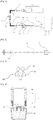
- Fig. 1 is a diagram of a continuous temperature measuring device according to one embodiment of the present invention.
- a continuous temperature measuring device includes a light-to-temperature converter 110 that measures temperature based on received light, a light guide rod 120 that receives light from a measurement target, an optical fiber 130 that transfers the light received by the light guide rod 120 to the light-to-temperature converter, a connector 140 through which the optical fiber 130 is connected to the light guide rod 120 while being maintained in a straight state, a primary protection tube 150 that encloses an outer peripheral surface of the light guide rod 120, and a flexible heat resistant tube 160 that protects the optical fiber.
- the light-to-temperature converter 110 may include a radiation pyrometer that receives light to thereby generate an electrical signal and a display that displays a measured temperature.
- the continuous temperature measuring device measures a temperature through an optical method.
- slag float in a ladle it is difficult to measure temperature from above the ladle in the optical method.
- the method of measuring temperature through direct contact of the optical fiber with molten metal to receive light is disclosed in US Patent Publication No. 2007-0268477 presented in the description of the related art, in which the optical fiber is dipped in the molten metal and thus consumed, thereby causing cost increase.
- the present invention can remove an unnecessary process, such as continuous dipping of the optical fiber, by receiving light from the molten steel exposed to the pressure reduced atmosphere.
- the optical fiber since the optical fiber has weak mechanical properties despite excellent flexibility, it is advantageous in terms of installation or high temperature durability that the optical fiber is connected to the vacuum vessel of a measurement side through a separate member for light reception while being directly connected to the light-to-temperature converter.
- the present invention provides a structure facilitating light reception within the vacuum vessel using the light guide rod and the optical fiber having excellent light transmittance.
- the light guide rod 120 is provided with a protrusion 122 protruding from an outer peripheral surface thereof, and the primary protection tube 150 is provided with a stopper 123 for stopping the protrusion 122 such that the light guide rod 120 is not separated from the primary protection tube 150.
- the light guide rod 120 serves to guide light and may be formed of a transparent material that does not deform at high temperature.
- the light guide rod 120 may be formed of quartz, sapphire, heat-resistant glass, transparent synthetic resin, or the like.
- the protrusion 122 is formed on a smooth surface of the light guide rod 120 and the stopper 123 for stopping the protrusion 122 is provided to the primary protection tube 150, thereby providing a desirable structure for leakage prevention.
- the primary protection tube 150 may be formed with a structure in which the primary protection tube 150 is divided into left and right sections, which are coupled to each other, with the stopper 122 placed at the center there between.
- the primary protection tube 150 encloses the outer peripheral surface of the light guide rod 120 to protect the light guide rod 120, thereby reinforcing the light guide rod 120.
- the continuous temperature measuring device may include a joint 170 connected to the flexible heat resistant tube and provided with a cooling gas injection tube 172.
- the cooling gas injection tube 172 may be inclined at an obtuse angle with respect to a direction toward the light guide rod 120 such that the joint 170 may introduce cooling gas in the direction toward the light guide rod 120.
- the cooling gas injection tube 172 is configured to allow the introduced cooling gas to flow smoothly in the direction toward the light guide rod 120 and not toward the light-to-temperature converter 110, thereby supplying the cooling gas without pressure drop.
- such a cooling gas supply structure using the joint 170 may prevent high temperature molten steel from directly damaging or deforming the light guide rod 120 due to a room temperature or low temperature cooling gas.
- the primary protection tube 150 may be inserted into a secondary protection tube 180 such that the cooling gas may flow into a space between the primary and secondary protection tubes 150, 180. Namely, an outer surface of the primary protection tube 150 and an inner surface of the secondary protection tube 180 are separated a predetermined distance from each other such that the cooling gas can flow into the space there between.
- the continuous temperature measuring device may further include a securing member 190 connecting the primary and secondary protection tubes 150, 180 so as to maintain straightness of the primary and secondary protection tubes 150, 180 and having a communication recess through which the cooling gas flows.
- the primary protection tube 150 serves to protect the light guide rod 120 so as to prevent damage of the light guide rod 120 due to vibration.
- the primary protection tube 150 is disposed within the secondary protection tube 180 such that a cooling gas channel is formed between the primary and secondary protection tubes 150, 180, the securing member 190 capable of tightly securing the primary protection tube 150 to the secondary protection tube 180 is required.
- Fig. 2 shows a state where the securing member 190 is attached to the primary protection tube 150
- Fig. 3 is a front view of the securing member 190.
- the securing member 190 connects the primary protection tube 150 to the secondary protection tube 180. As shown in Fig. 3 , an inner peripheral surface of the securing member 190 is attached to the primary protection tube 150, and an outer peripheral surface of the securing member 190 may be composed of contact surfaces 192 attached to the inner surface of the secondary protection tube 180 and non-contact surfaces 194 separated from the inner surface of the secondary protection tube 180.
- the inner peripheral surface of the securing member 190 may also be composed of contact surfaces attached to the outer peripheral surface of the primary protection tube 150 and non-contact surfaces not attached to the outer peripheral surface of the primary protection tube 150.
- the securing member 190 may also be configured in a shape in which the inner peripheral surface thereof is attached to the primary protection tube 150, the outer peripheral surface thereof is attached to the secondary protection tube 180, and through-holes through which the cooling gas flows are formed therethrough.
- the continuous temperature measuring device includes the connector 140, which connects the light guide rod 120 to the optical fiber 130 and serves to maintain straightness of the optical fiber 130 having no stiffness.
- FC connector may be used as the connector 140.
- the FC connector may be formed through filling of an epoxy resin, and deviation of measured temperature may be generated due to light reception when the epoxy resin generally used at a temperature of 150 degrees Celsius is exposed to a high temperature environment.
- thermocouple 142 may be attached to the connector 140.
- a temperature raise may result in an error.
- the thermocouple can be used to correct for this error.
- thermocouple measurement device is additionally provided to the light-to-temperature converter 110 by extending a compensating lead wire into the flexible heat resistant tube 160, thereby making it possible to monitor temperature increase of the connector 140 and cope with change in a temperature measurement environment.
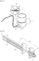
- Fig. 4 is a schematic view of a general RH apparatus.
- molten iron prepared by melting iron ore in a blast furnace has a high carbon content
- carbon in the molten iron is removed to a predetermined content (about 0.04%) by dipping the molten iron in a converter and bubbling with pure oxygen gas in the steel making process.
- the molten iron, the carbon content of which is reduced to a predetermined level, is referred to as molten steel.
- the molten steel is fed into the RH apparatus.
- the molten steel is intensely stirred under vacuum such that the components and temperature of the molten steel become uniform and the remaining gas components are removed from the molten steel. Thereafter, the molten steel is fed into a continuous casting process.
- the RH apparatus for performing a vacuum degassing process includes a vacuum vessel 10 including an upper vessel 12 and a lower vessel 14, a ladle 20 placed below the vacuum vessel 10 and storing molten steel, a riser tube 30 through which the molten steel stored in the ladle 20 is suctioned into the vacuum vessel 10 by reduced pressure within the vacuum vessel, and a downcomer tube 40 through which the molten steel within the vacuum vessel is discharged into the ladle 20.
- An exhaust port 16 to which an exhaust pump is connected is formed in the vacuum vessel 10.
- the RH apparatus circulates the molten steel through the two circulation tubes including the riser tube through which the molten steel stored in the ladle 20 is suctioned into the vacuum vessel 10 by reduced pressure within the vacuum vessel 10 and the downcomer tube through which the molten steel within the vacuum vessel is discharged into the ladle.
- the RH apparatus blows argon gas through a nozzle provided to the riser tube 30 to decrease apparent specific gravity of the molten steel, thereby causing a height difference of the molten steel within the vacuum vessel 10, and decreases partial pressure of gas-phase molecules within the molten steel in a pressure reduced atmosphere to thereby perform the degassing process.
- Fig. 5 is a schematic view of an RH apparatus according to one embodiment of the present invention
- Fig. 6 is a view of an internal structure of a secondary protection tube in the RH apparatus according to the embodiment of the present invention.
- the RH apparatus includes a sensor hole 15 formed at a lower vessel 14 of a vacuum vessel 10; a continuous temperature measuring device 100 mounted on the sensor hole and including a light-to-temperature converter that measures temperature based on received light, a light guide rod 120 (located inside a primary protection tube in Fig.
- the RH apparatus further includes a secondary protection tube 180 including a flange tube 182 extending from the sensor hole and an external flange tube 184 that encloses an outer peripheral surface of the primary protection tube 150, forms a cooling gas channel between the primary protection tube 150 and the external flange tube 184, and coupled to the flange tube.
- a secondary protection tube 180 including a flange tube 182 extending from the sensor hole and an external flange tube 184 that encloses an outer peripheral surface of the primary protection tube 150, forms a cooling gas channel between the primary protection tube 150 and the external flange tube 184, and coupled to the flange tube.
- the primary protection tube 150 is secured to an interior of the secondary protection tube 180 through a securing member 190.
- the securing member 190 is provided with a communication recess through which the cooling gas (shown by a dotted line) may flow.
- the RH apparatus may further include a heat shield plate 185, shielding radiant heat, below the flange tube 182 and the external flange tube 184.
- the heat shield plate 185 for shielding the radiant heat may be disposed below the flange tube 182 and the external flange tube 184, thereby preventing overheating of the continuous temperature measuring device.
- the sensor hole 15 may be formed such that temperature in an area between the riser and downcomer tubes may be measured. Further, the sensor hole 15 may be formed at a height of 100 mm to 300 mm from a bottom of the lower vessel 14.
- the molten steel descends into the ladle after being completely processed, and skulls falling from upper and inner sides of the vacuum vessel may be stacked at a lower portion of the vacuum vessel, in which pressure has been restored. At this time, some of the skulls stacked at the lower portion of the vacuum vessel are welded on the sensor hole 15 or close the sensor hole 15 to block out light, thereby causing problems in subsequent use of the ladle.
- the molten steel does not reach the sensor hole while being processed, thereby causing the molten steel to be inaccurately received.
- the sensor hole 15 Another important factor in the arrangement of the sensor hole 15 is a correlation between the sensor hole 15 and dip tubes.
- a carrier gas is used to suction the molten steel in the two dip tubes including the riser and downcomer tubes which are alternately used, and melting loss of a refractory material around the dip tubes becomes serious due to the carrier gas and suctioning of the molten steel.
- the continuous temperature measuring device according to the present invention is mounted inside the refractory material of the lower vessel, melting loss of the refractory material may lead to exposure of the light guide rod, which can cause deviation of measured temperatures due to deformation of the light guide rod at high temperature.
- the sensor hole may be disposed in the area between the riser tube and the downcomer tube.
- a light reception end of the light guide rod be placed within a distance of 100 mm to 200 mm from the refractory material.
- a quartz bar can be directly exposed to the molten steel, thereby causing measurement deviation due to high temperature deformation.
- the light guide rod does cannot receive light from the molten steel.
- the cooling gas supplied from the cooling gas supply unit is introduced in a direction of a light source through the joint connected to a portion of the flexible heat resistant tube, passes between the primary and secondary protection tubes, and protects the light guide rod from the molten steel and the high temperature of the molten steel.
- the protrusion formed on the light guide rod and the stopper installed in the primary protection tube may prevent the light guide rod from being suctioned into the vacuum vessel under reduced pressure.
Landscapes
- Physics & Mathematics (AREA)
- General Physics & Mathematics (AREA)
- Spectroscopy & Molecular Physics (AREA)
- Chemical & Material Sciences (AREA)
- Engineering & Computer Science (AREA)
- Materials Engineering (AREA)
- Metallurgy (AREA)
- Organic Chemistry (AREA)
- Manufacturing & Machinery (AREA)
- Mechanical Engineering (AREA)
- General Engineering & Computer Science (AREA)
- Radiation Pyrometers (AREA)
- Treatment Of Steel In Its Molten State (AREA)
- Waste-Gas Treatment And Other Accessory Devices For Furnaces (AREA)
- Investigating Or Analyzing Materials Using Thermal Means (AREA)
Claims (12)
- Kontinuierliche Temperaturmessvorrichtung für ein RH-Gerät, umfassend:einen Licht-Temperatur-Wandler (110), der die Temperatur basierend auf empfangenem Licht misst;einen Lichtleiterstab (120), der Licht von einem Messziel empfängt;eine optische Faser (130), die das von dem Lichtleiterstab (120) empfangene Licht zu dem Licht-Temperatur-Wandler (110) überträgt;einen Verbinder (140), der die optische Faser (130) mit dem Lichtleiterstab (120) verbindet, während die Geradheit der optischen Faser (130) beibehalten wird;ein primäres Schutzrohr (150), das eine äußere Umfangsfläche des Lichtleiterstabes (120) umschließt; undeinen flexiblen hitzebeständigen Schlauch (160), der die optische Faser (130) schützt.
- Kontinuierliche Temperaturmessvorrichtung nach Anspruch 1, ferner umfassend: ein sekundäres Schutzrohr (180), das eine äußere Umfangsfläche des primären Schutzrohrs (150) umschließt und einen Kühlgaskanal zwischen dem primären (150) und dem sekundären (180) Schutzrohr bildet; und
eine Verbindung (170), die mit dem flexiblen hitzebeständigen Schlauch (160) verbunden und mit einem Kühlgaseinspritzrohr (172) versehen ist;. - Kontinuierliche Temperaturmessvorrichtung nach Anspruch 2, wobei das Kühlgaseinspritzrohr (172) in einem stumpfen Winkel bezüglich einer Richtung zum Lichtleiterstab (120) geneigt ist.
- Kontinuierliche Temperaturmessvorrichtung nach Anspruch 2, ferner umfassend: ein Sicherungselement (190), das zwischen dem primären und dem sekundären Schutzrohr (180) angeschlossen ist, um die Geradheit des primären (150) und des sekundären (180) Schutzrohres aufrechtzuerhalten, und das eine Verbindungsaussparung aufweist, durch die ein Kühlgas fließt.
- Kontinuierliche Temperaturmessvorrichtung nach Anspruch 1, wobei der Lichtleiterstab (120) mit einem Vorsprung (122) und das primäre Schutzrohr (150) mit einem Anschlag (123) zum Stoppen des Vorsprungs (122) versehen ist, so dass der Lichtleiterstab (120) nicht vom primären Schutzrohr (150) getrennt ist.
- Kontinuierliche Temperaturmessvorrichtung nach Anspruch 5, wobei das primäre Schutzrohr (150) in zwei Abschnitte unterteilt ist, die an beiden Seiten des Vorsprungs (122) ausgebildet sind, wobei die beiden Abschnitte miteinander gekoppelt sind, wobei der Anschlag (123) in einer Mitte dazwischen angeordnet ist.
- Kontinuierliche Temperaturmessvorrichtung nach Anspruch 1, ferner umfassend: ein Thermoelement (142) mit einer an dem Verbinder (140) ausgebildeten Temperaturmessstelle.
- RH-Gerät zur Durchführung eines Vakuumentgasungsverfahrens von geschmolzenem Metall, wobei das RH-Gerät umfasst:ein Sensorloch (15), das an einem unteren Behälter (14) eines Vakuumbehälters (10) ausgebildet ist;eine kontinuierliche Temperaturmessvorrichtung, die an dem Sensorloch (15) angebracht ist, wobei die kontinuierliche Temperaturmessvorrichtung einen Licht-Temperatur-Wandler (110), der die Temperatur basierend auf empfangenem Licht misst, einen Lichtleiterstab (120), der Licht von einem Messziel empfängt, eine optische Faser (130), die das von dem Lichtleiterstab (120) empfangene Licht zu dem Licht-Temperatur-Wandler (110) überträgt, einen Verbinder (140), der die optische Faser (130) mit dem Lichtleiterstab (120) verbindet, während die Geradheit der optischen Faser (130) beibehalten wird, ein primäres Schutzrohr (150), das eine äußere Umfangsfläche des Lichtleiterstabes (120) umschließt, einen flexiblen hitzebeständigen Schlauch (160), der die optische Faser (130) schützt, und eine Verbindung (170), die mit dem flexiblen hitzebeständigen Schlauch (160) verbunden und mit einem Kühlgaseinspritzrohr (172) versehen ist, umfasst;eine Kühlgasversorgungseinheit, die das Kühlgaseinspritzrohr (172) mit Kühlgas versorgt; und ein Flanschrohr (182), das sich von dem Sensorloch (15) erstreckt; undein äußeres Flanschrohr (184), das eine äußere Umfangsfläche des primären Schutzrohres (150) umschließt, sodass ein Kühlgaskanal zwischen dem primären Schutzrohr (150) und dem äußeren Flanschrohr (184) gebildet wird, und das mit dem Flanschrohr (182) gekoppelt ist,wobei das Kühlgas zwischen dem Flanschrohr (182) und dem äußeren Flanschrohr (184) zugeführt wird.
- RH-Gerät nach Anspruch 8, ferner umfassend:
eine Hitzeschildplatte (185) zum Abschirmen von Strahlungswärme unter dem Flanschrohr (182) und dem äußeren Flanschrohr (184). - RH-Gerät nach Anspruch 8, wobei das Sensorloch (15) ausgebildet ist, um die Temperatur in einem Bereich zwischen einem Steigrohr (30) und einem Fallrohr (40) zu messen.
- RH-Gerät nach Anspruch 8, wobei das Sensorloch (15) in einer Höhe von 100 mm bis 300 mm von einem Boden des unteren Behälters (14) ausgebildet ist.
- RH-Gerät nach Anspruch 8, wobei ein Lichtempfangsende des Lichtleiterstabes (120) in einem Abstand von 100 mm bis 200 mm von einem feuerfesten Material angeordnet ist.
Applications Claiming Priority (2)
| Application Number | Priority Date | Filing Date | Title |
|---|---|---|---|
| KR1020130145610A KR101450651B1 (ko) | 2013-11-27 | 2013-11-27 | 연속 측온 장치 및 이를 포함하는 rh장치 |
| PCT/KR2014/011308 WO2015080443A1 (en) | 2013-11-27 | 2014-11-24 | Continuous temperature measuring device and rh apparatus including the same |
Publications (3)
| Publication Number | Publication Date |
|---|---|
| EP3074741A1 EP3074741A1 (de) | 2016-10-05 |
| EP3074741A4 EP3074741A4 (de) | 2017-07-26 |
| EP3074741B1 true EP3074741B1 (de) | 2018-07-25 |
Family
ID=51997648
Family Applications (1)
| Application Number | Title | Priority Date | Filing Date |
|---|---|---|---|
| EP14866094.7A Not-in-force EP3074741B1 (de) | 2013-11-27 | 2014-11-24 | Kontinuierliche temperaturmessvorrichtung und rh-vorrichtung damit |
Country Status (9)
| Country | Link |
|---|---|
| US (1) | US9689048B2 (de) |
| EP (1) | EP3074741B1 (de) |
| JP (2) | JP2017500554A (de) |
| KR (1) | KR101450651B1 (de) |
| CN (1) | CN106133489A (de) |
| BR (1) | BR112016011945A2 (de) |
| RU (1) | RU2652648C2 (de) |
| TW (1) | TWI548865B (de) |
| WO (1) | WO2015080443A1 (de) |
Families Citing this family (3)
| Publication number | Priority date | Publication date | Assignee | Title |
|---|---|---|---|---|
| CN108303183B (zh) * | 2018-04-11 | 2023-06-20 | 中国电子科技集团公司第三十四研究所 | 接近式宽波段光学高温计 |
| KR102063487B1 (ko) * | 2018-10-24 | 2020-01-08 | (주)화이버 옵틱코리아 | 가열로용 광섬유 진단센서 |
| CN115371843B (zh) * | 2022-09-21 | 2025-04-18 | 中冶赛迪工程技术股份有限公司 | 一种自动测温取样装置用冷却测枪 |
Family Cites Families (28)
| Publication number | Priority date | Publication date | Assignee | Title |
|---|---|---|---|---|
| JPS5735736A (en) * | 1980-08-13 | 1982-02-26 | Nippon Kinzoku Kogyo Kk | Continuous temperature measuring method of molten metal |
| JPS58167732A (ja) * | 1982-03-30 | 1983-10-04 | Daido Steel Co Ltd | 金属溶湯の真空脱ガス方法 |
| JPS61149423A (ja) * | 1984-12-25 | 1986-07-08 | Kawasaki Steel Corp | 加熱電極を備えた真空脱ガス装置の操業方法 |
| DE3878791T2 (de) * | 1987-08-27 | 1993-06-09 | American Telephone & Telegraph | Faseroptisches kabel fuer anwendung in hochtemperaturumgebung. |
| US6004031A (en) | 1993-11-30 | 1999-12-21 | Nkk Corporation | Temperature measuring device |
| US5841545A (en) * | 1994-09-19 | 1998-11-24 | Lockheed Martin Energy Systems, Inc. | Multi-function diamond film fiberoptic probe and measuring system employing same |
| KR100287568B1 (ko) | 1995-11-17 | 2001-04-16 | 마리오 파텍 | 스틸 용융체를 탈탄하기 위한 방법 및 장치 |
| JPH09257580A (ja) * | 1996-03-21 | 1997-10-03 | Meidensha Corp | 温度検出器 |
| CN1063546C (zh) | 1996-08-23 | 2001-03-21 | 中国工程物理研究院流体物理研究所 | 熔质内部高温跟踪测量方法及装置 |
| WO1998046971A1 (en) * | 1997-04-14 | 1998-10-22 | Molten Metal Technology, Inc. | Device and method for measuring physical characteristics of molten baths |
| DE19736276B4 (de) | 1997-08-21 | 2006-07-27 | Alstom Technology Ltd | Optisches Pyrometer für Gasturbinen |
| US6226453B1 (en) | 1997-09-16 | 2001-05-01 | Applied Materials, Inc. | Temperature probe with fiber optic core |
| RU2150091C1 (ru) * | 1998-04-17 | 2000-05-27 | Научно-исследовательский институт Радиоэлектронных Систем Прогнозирования Чрезвычайных Ситуаций (НИИ "Прогноз") | Способ измерения температуры расплава и устройство для его осуществления |
| US6190037B1 (en) * | 1999-02-19 | 2001-02-20 | Applied Materials, Inc. | Non-intrusive, on-the-fly (OTF) temperature measurement and monitoring system |
| US6175676B1 (en) * | 1999-02-23 | 2001-01-16 | Bethlehem Steel Corporation | Fiber optic sensor and method of use thereof to determine carbon content of molten steel contained in a basic oxygen furnace |
| JP2001091362A (ja) * | 1999-09-22 | 2001-04-06 | Tokai Carbon Co Ltd | 表面温度測定方法および装置 |
| US6647350B1 (en) * | 2000-06-02 | 2003-11-11 | Exactus, Inc. | Radiometric temperature measurement system |
| ITMI20012278A1 (it) * | 2001-10-30 | 2003-04-30 | Techint Spa | Dispositivo e metodo per misurazione discreta e continua della temperatura di metallo liquido in un forno o recipiente per la sua produzione |
| DE10253463A1 (de) * | 2002-11-16 | 2004-06-03 | Gecon Engineering Gmbh | Verfahren und Vorrichtung zur Kühlung von Blaslanzen |
| DE10331124B3 (de) | 2003-07-09 | 2005-02-17 | Heraeus Electro-Nite International N.V. | Verfahren und Vorrichtung zum Messen der Abkühlkurve von Schmelzenproben und/oder der Aufheizkurve von Schmelzenproben sowie deren Verwendung |
| US6964516B2 (en) * | 2004-02-11 | 2005-11-15 | Heraeus-Electro Nite International N.V. | Device and method for measuring temperature in molten metals |
| WO2007037771A1 (en) | 2004-05-13 | 2007-04-05 | Honeywell International Inc. | High temperature pyrometer |
| BRPI0502779B1 (pt) * | 2005-06-09 | 2020-09-29 | Usinas Siderúrgicas De Minas Gerais S.A. - Usiminas | Dispositivo para medição contínua de temperatura do aço líquido no distribuidor com pirômetro infravermelho e fibra óptica |
| DE102005040311B3 (de) | 2005-08-24 | 2006-10-26 | Heraeus Electro-Nite International N.V. | Vorrichtung zur Temperaturmessung in Metallschmelzen |
| GB2438214A (en) | 2006-05-19 | 2007-11-21 | Heraeus Electro Nite Int | Measuring a parameter of a molten bath |
| CN100549188C (zh) * | 2006-06-01 | 2009-10-14 | 上海宝钢工程技术有限公司 | 钢水精炼真空槽待机预热装置及方法 |
| JP5299032B2 (ja) * | 2009-04-01 | 2013-09-25 | 新日鐵住金株式会社 | 溶鋼の連続測温方法 |
| CN201926511U (zh) * | 2010-12-18 | 2011-08-10 | 莘县荣盛精密铸造有限公司 | 热电偶用保护管 |
-
2013
- 2013-11-27 KR KR1020130145610A patent/KR101450651B1/ko not_active Expired - Fee Related
-
2014
- 2014-11-24 CN CN201480065092.XA patent/CN106133489A/zh active Pending
- 2014-11-24 WO PCT/KR2014/011308 patent/WO2015080443A1/en not_active Ceased
- 2014-11-24 US US15/039,494 patent/US9689048B2/en not_active Expired - Fee Related
- 2014-11-24 RU RU2016125234A patent/RU2652648C2/ru not_active IP Right Cessation
- 2014-11-24 EP EP14866094.7A patent/EP3074741B1/de not_active Not-in-force
- 2014-11-24 JP JP2016534723A patent/JP2017500554A/ja active Pending
- 2014-11-24 BR BR112016011945A patent/BR112016011945A2/pt not_active Application Discontinuation
- 2014-11-27 TW TW103141257A patent/TWI548865B/zh not_active IP Right Cessation
-
2018
- 2018-01-24 JP JP2018009893A patent/JP2018109633A/ja active Pending
Also Published As
| Publication number | Publication date |
|---|---|
| KR101450651B1 (ko) | 2014-10-15 |
| JP2018109633A (ja) | 2018-07-12 |
| WO2015080443A1 (en) | 2015-06-04 |
| EP3074741A1 (de) | 2016-10-05 |
| CN106133489A (zh) | 2016-11-16 |
| US20160376671A1 (en) | 2016-12-29 |
| JP2017500554A (ja) | 2017-01-05 |
| RU2016125234A (ru) | 2018-01-09 |
| US9689048B2 (en) | 2017-06-27 |
| RU2652648C2 (ru) | 2018-04-28 |
| BR112016011945A2 (pt) | 2017-08-08 |
| TW201531679A (zh) | 2015-08-16 |
| TWI548865B (zh) | 2016-09-11 |
| EP3074741A4 (de) | 2017-07-26 |
Similar Documents
| Publication | Publication Date | Title |
|---|---|---|
| JP6122902B2 (ja) | 溶融金属の温度を測定するための装置 | |
| KR101679115B1 (ko) | 용융 금속의 온도를 측정하는 방법 및 장치 | |
| US9689048B2 (en) | Continuous temperature measuring device and RH apparatus including the same | |
| KR101750650B1 (ko) | 용융물의 온도를 측정하기 위한 광섬유 급송 디바이스 | |
| US6964516B2 (en) | Device and method for measuring temperature in molten metals | |
| JP2008545975A (ja) | 光ファイバおよび赤外線パイロメータを用いたタンディッシュ内の溶鋼の連続的な温度測定のための装置 | |
| JP4616456B2 (ja) | 溶融金属温度測定用の浸漬型光ファイバ放射温度計及び溶融金属の温度測定方法 | |
| JP5299032B2 (ja) | 溶鋼の連続測温方法 | |
| KR20040049854A (ko) | 고온계 | |
| CA2508582C (en) | Guide system for signal lines, device for measuring temperatures and/or concentrations and use | |
| JPS62132135A (ja) | 溶融金属温度連続測定方法 | |
| KR200245046Y1 (ko) | 전로용 서브랜스 복합프로브 | |
| KR20220089480A (ko) | 고로의 용선 온도 측정장치 | |
| JP2003294534A (ja) | 溶融金属の測温装置 | |
| KR20100039967A (ko) | 비접촉식 온도 측정 장치 및 그 방법 | |
| JP5073269B2 (ja) | Rh装置の鉄皮冷却方法 | |
| JP2002146426A (ja) | 溶鋼放射測温方法 | |
| JP2001083013A (ja) | 溶融金属の測温装置 | |
| JP2001303121A (ja) | 精錬容器の内側表面の温度測定方法 | |
| JP2012197478A (ja) | 羽口ユニットおよび熱電対交換方法 | |
| JPH02209416A (ja) | 脱ガス精錬における湯面監視方法 |
Legal Events
| Date | Code | Title | Description |
|---|---|---|---|
| PUAI | Public reference made under article 153(3) epc to a published international application that has entered the european phase |
Free format text: ORIGINAL CODE: 0009012 |
|
| 17P | Request for examination filed |
Effective date: 20160420 |
|
| AK | Designated contracting states |
Kind code of ref document: A1 Designated state(s): AL AT BE BG CH CY CZ DE DK EE ES FI FR GB GR HR HU IE IS IT LI LT LU LV MC MK MT NL NO PL PT RO RS SE SI SK SM TR |
|
| AX | Request for extension of the european patent |
Extension state: BA ME |
|
| DAX | Request for extension of the european patent (deleted) | ||
| A4 | Supplementary search report drawn up and despatched |
Effective date: 20170623 |
|
| RIC1 | Information provided on ipc code assigned before grant |
Ipc: C21C 7/10 20060101ALI20170619BHEP Ipc: G01J 5/02 20060101ALI20170619BHEP Ipc: F27D 21/00 20060101ALI20170619BHEP Ipc: G01J 5/28 20060101AFI20170619BHEP Ipc: G01K 13/00 20060101ALI20170619BHEP |
|
| GRAP | Despatch of communication of intention to grant a patent |
Free format text: ORIGINAL CODE: EPIDOSNIGR1 |
|
| STAA | Information on the status of an ep patent application or granted ep patent |
Free format text: STATUS: GRANT OF PATENT IS INTENDED |
|
| RIC1 | Information provided on ipc code assigned before grant |
Ipc: F27D 21/00 20060101ALI20180417BHEP Ipc: C21C 7/10 20060101ALI20180417BHEP Ipc: G01K 13/00 20060101ALI20180417BHEP Ipc: G01J 5/28 20060101AFI20180417BHEP Ipc: G01J 5/02 20060101ALI20180417BHEP |
|
| INTG | Intention to grant announced |
Effective date: 20180508 |
|
| RIN1 | Information on inventor provided before grant (corrected) |
Inventor name: KIM, YEONG-IN Inventor name: YOU, JONG-AN Inventor name: PARK, KWANG-SUN |
|
| GRAS | Grant fee paid |
Free format text: ORIGINAL CODE: EPIDOSNIGR3 |
|
| GRAA | (expected) grant |
Free format text: ORIGINAL CODE: 0009210 |
|
| STAA | Information on the status of an ep patent application or granted ep patent |
Free format text: STATUS: THE PATENT HAS BEEN GRANTED |
|
| AK | Designated contracting states |
Kind code of ref document: B1 Designated state(s): AL AT BE BG CH CY CZ DE DK EE ES FI FR GB GR HR HU IE IS IT LI LT LU LV MC MK MT NL NO PL PT RO RS SE SI SK SM TR |
|
| REG | Reference to a national code |
Ref country code: GB Ref legal event code: FG4D |
|
| REG | Reference to a national code |
Ref country code: CH Ref legal event code: EP |
|
| REG | Reference to a national code |
Ref country code: AT Ref legal event code: REF Ref document number: 1022265 Country of ref document: AT Kind code of ref document: T Effective date: 20180815 |
|
| REG | Reference to a national code |
Ref country code: IE Ref legal event code: FG4D |
|
| REG | Reference to a national code |
Ref country code: DE Ref legal event code: R096 Ref document number: 602014029349 Country of ref document: DE |
|
| REG | Reference to a national code |
Ref country code: NL Ref legal event code: MP Effective date: 20180725 |
|
| REG | Reference to a national code |
Ref country code: LT Ref legal event code: MG4D |
|
| PG25 | Lapsed in a contracting state [announced via postgrant information from national office to epo] |
Ref country code: NL Free format text: LAPSE BECAUSE OF FAILURE TO SUBMIT A TRANSLATION OF THE DESCRIPTION OR TO PAY THE FEE WITHIN THE PRESCRIBED TIME-LIMIT Effective date: 20180725 |
|
| REG | Reference to a national code |
Ref country code: AT Ref legal event code: MK05 Ref document number: 1022265 Country of ref document: AT Kind code of ref document: T Effective date: 20180725 |
|
| PG25 | Lapsed in a contracting state [announced via postgrant information from national office to epo] |
Ref country code: IS Free format text: LAPSE BECAUSE OF FAILURE TO SUBMIT A TRANSLATION OF THE DESCRIPTION OR TO PAY THE FEE WITHIN THE PRESCRIBED TIME-LIMIT Effective date: 20181125 Ref country code: LT Free format text: LAPSE BECAUSE OF FAILURE TO SUBMIT A TRANSLATION OF THE DESCRIPTION OR TO PAY THE FEE WITHIN THE PRESCRIBED TIME-LIMIT Effective date: 20180725 Ref country code: RS Free format text: LAPSE BECAUSE OF FAILURE TO SUBMIT A TRANSLATION OF THE DESCRIPTION OR TO PAY THE FEE WITHIN THE PRESCRIBED TIME-LIMIT Effective date: 20180725 Ref country code: AT Free format text: LAPSE BECAUSE OF FAILURE TO SUBMIT A TRANSLATION OF THE DESCRIPTION OR TO PAY THE FEE WITHIN THE PRESCRIBED TIME-LIMIT Effective date: 20180725 Ref country code: PL Free format text: LAPSE BECAUSE OF FAILURE TO SUBMIT A TRANSLATION OF THE DESCRIPTION OR TO PAY THE FEE WITHIN THE PRESCRIBED TIME-LIMIT Effective date: 20180725 Ref country code: FI Free format text: LAPSE BECAUSE OF FAILURE TO SUBMIT A TRANSLATION OF THE DESCRIPTION OR TO PAY THE FEE WITHIN THE PRESCRIBED TIME-LIMIT Effective date: 20180725 Ref country code: NO Free format text: LAPSE BECAUSE OF FAILURE TO SUBMIT A TRANSLATION OF THE DESCRIPTION OR TO PAY THE FEE WITHIN THE PRESCRIBED TIME-LIMIT Effective date: 20181025 Ref country code: GR Free format text: LAPSE BECAUSE OF FAILURE TO SUBMIT A TRANSLATION OF THE DESCRIPTION OR TO PAY THE FEE WITHIN THE PRESCRIBED TIME-LIMIT Effective date: 20181026 Ref country code: SE Free format text: LAPSE BECAUSE OF FAILURE TO SUBMIT A TRANSLATION OF THE DESCRIPTION OR TO PAY THE FEE WITHIN THE PRESCRIBED TIME-LIMIT Effective date: 20180725 Ref country code: BG Free format text: LAPSE BECAUSE OF FAILURE TO SUBMIT A TRANSLATION OF THE DESCRIPTION OR TO PAY THE FEE WITHIN THE PRESCRIBED TIME-LIMIT Effective date: 20181025 |
|
| PGFP | Annual fee paid to national office [announced via postgrant information from national office to epo] |
Ref country code: DE Payment date: 20181120 Year of fee payment: 5 |
|
| PG25 | Lapsed in a contracting state [announced via postgrant information from national office to epo] |
Ref country code: HR Free format text: LAPSE BECAUSE OF FAILURE TO SUBMIT A TRANSLATION OF THE DESCRIPTION OR TO PAY THE FEE WITHIN THE PRESCRIBED TIME-LIMIT Effective date: 20180725 Ref country code: AL Free format text: LAPSE BECAUSE OF FAILURE TO SUBMIT A TRANSLATION OF THE DESCRIPTION OR TO PAY THE FEE WITHIN THE PRESCRIBED TIME-LIMIT Effective date: 20180725 Ref country code: LV Free format text: LAPSE BECAUSE OF FAILURE TO SUBMIT A TRANSLATION OF THE DESCRIPTION OR TO PAY THE FEE WITHIN THE PRESCRIBED TIME-LIMIT Effective date: 20180725 |
|
| REG | Reference to a national code |
Ref country code: DE Ref legal event code: R097 Ref document number: 602014029349 Country of ref document: DE |
|
| PG25 | Lapsed in a contracting state [announced via postgrant information from national office to epo] |
Ref country code: RO Free format text: LAPSE BECAUSE OF FAILURE TO SUBMIT A TRANSLATION OF THE DESCRIPTION OR TO PAY THE FEE WITHIN THE PRESCRIBED TIME-LIMIT Effective date: 20180725 Ref country code: IT Free format text: LAPSE BECAUSE OF FAILURE TO SUBMIT A TRANSLATION OF THE DESCRIPTION OR TO PAY THE FEE WITHIN THE PRESCRIBED TIME-LIMIT Effective date: 20180725 Ref country code: ES Free format text: LAPSE BECAUSE OF FAILURE TO SUBMIT A TRANSLATION OF THE DESCRIPTION OR TO PAY THE FEE WITHIN THE PRESCRIBED TIME-LIMIT Effective date: 20180725 Ref country code: CZ Free format text: LAPSE BECAUSE OF FAILURE TO SUBMIT A TRANSLATION OF THE DESCRIPTION OR TO PAY THE FEE WITHIN THE PRESCRIBED TIME-LIMIT Effective date: 20180725 Ref country code: EE Free format text: LAPSE BECAUSE OF FAILURE TO SUBMIT A TRANSLATION OF THE DESCRIPTION OR TO PAY THE FEE WITHIN THE PRESCRIBED TIME-LIMIT Effective date: 20180725 |
|
| PG25 | Lapsed in a contracting state [announced via postgrant information from national office to epo] |
Ref country code: DK Free format text: LAPSE BECAUSE OF FAILURE TO SUBMIT A TRANSLATION OF THE DESCRIPTION OR TO PAY THE FEE WITHIN THE PRESCRIBED TIME-LIMIT Effective date: 20180725 Ref country code: SK Free format text: LAPSE BECAUSE OF FAILURE TO SUBMIT A TRANSLATION OF THE DESCRIPTION OR TO PAY THE FEE WITHIN THE PRESCRIBED TIME-LIMIT Effective date: 20180725 Ref country code: SM Free format text: LAPSE BECAUSE OF FAILURE TO SUBMIT A TRANSLATION OF THE DESCRIPTION OR TO PAY THE FEE WITHIN THE PRESCRIBED TIME-LIMIT Effective date: 20180725 |
|
| PLBE | No opposition filed within time limit |
Free format text: ORIGINAL CODE: 0009261 |
|
| STAA | Information on the status of an ep patent application or granted ep patent |
Free format text: STATUS: NO OPPOSITION FILED WITHIN TIME LIMIT |
|
| REG | Reference to a national code |
Ref country code: CH Ref legal event code: PL |
|
| 26N | No opposition filed |
Effective date: 20190426 |
|
| GBPC | Gb: european patent ceased through non-payment of renewal fee |
Effective date: 20181124 |
|
| PG25 | Lapsed in a contracting state [announced via postgrant information from national office to epo] |
Ref country code: MC Free format text: LAPSE BECAUSE OF FAILURE TO SUBMIT A TRANSLATION OF THE DESCRIPTION OR TO PAY THE FEE WITHIN THE PRESCRIBED TIME-LIMIT Effective date: 20180725 Ref country code: LU Free format text: LAPSE BECAUSE OF NON-PAYMENT OF DUE FEES Effective date: 20181124 |
|
| REG | Reference to a national code |
Ref country code: BE Ref legal event code: MM Effective date: 20181130 |
|
| REG | Reference to a national code |
Ref country code: IE Ref legal event code: MM4A |
|
| PG25 | Lapsed in a contracting state [announced via postgrant information from national office to epo] |
Ref country code: CH Free format text: LAPSE BECAUSE OF NON-PAYMENT OF DUE FEES Effective date: 20181130 Ref country code: SI Free format text: LAPSE BECAUSE OF FAILURE TO SUBMIT A TRANSLATION OF THE DESCRIPTION OR TO PAY THE FEE WITHIN THE PRESCRIBED TIME-LIMIT Effective date: 20180725 Ref country code: LI Free format text: LAPSE BECAUSE OF NON-PAYMENT OF DUE FEES Effective date: 20181130 |
|
| PG25 | Lapsed in a contracting state [announced via postgrant information from national office to epo] |
Ref country code: FR Free format text: LAPSE BECAUSE OF NON-PAYMENT OF DUE FEES Effective date: 20181130 Ref country code: IE Free format text: LAPSE BECAUSE OF NON-PAYMENT OF DUE FEES Effective date: 20181124 |
|
| REG | Reference to a national code |
Ref country code: DE Ref legal event code: R082 Ref document number: 602014029349 Country of ref document: DE Representative=s name: BRAND, NORMEN, DIPL.-CHEM. UNIV. DR. RER. NAT., DE |
|
| PG25 | Lapsed in a contracting state [announced via postgrant information from national office to epo] |
Ref country code: BE Free format text: LAPSE BECAUSE OF NON-PAYMENT OF DUE FEES Effective date: 20181130 |
|
| PG25 | Lapsed in a contracting state [announced via postgrant information from national office to epo] |
Ref country code: GB Free format text: LAPSE BECAUSE OF NON-PAYMENT OF DUE FEES Effective date: 20181124 |
|
| PG25 | Lapsed in a contracting state [announced via postgrant information from national office to epo] |
Ref country code: MT Free format text: LAPSE BECAUSE OF NON-PAYMENT OF DUE FEES Effective date: 20181124 |
|
| PG25 | Lapsed in a contracting state [announced via postgrant information from national office to epo] |
Ref country code: TR Free format text: LAPSE BECAUSE OF FAILURE TO SUBMIT A TRANSLATION OF THE DESCRIPTION OR TO PAY THE FEE WITHIN THE PRESCRIBED TIME-LIMIT Effective date: 20180725 |
|
| PG25 | Lapsed in a contracting state [announced via postgrant information from national office to epo] |
Ref country code: PT Free format text: LAPSE BECAUSE OF FAILURE TO SUBMIT A TRANSLATION OF THE DESCRIPTION OR TO PAY THE FEE WITHIN THE PRESCRIBED TIME-LIMIT Effective date: 20180725 |
|
| REG | Reference to a national code |
Ref country code: DE Ref legal event code: R119 Ref document number: 602014029349 Country of ref document: DE |
|
| PG25 | Lapsed in a contracting state [announced via postgrant information from national office to epo] |
Ref country code: MK Free format text: LAPSE BECAUSE OF NON-PAYMENT OF DUE FEES Effective date: 20180725 Ref country code: HU Free format text: LAPSE BECAUSE OF FAILURE TO SUBMIT A TRANSLATION OF THE DESCRIPTION OR TO PAY THE FEE WITHIN THE PRESCRIBED TIME-LIMIT; INVALID AB INITIO Effective date: 20141124 Ref country code: CY Free format text: LAPSE BECAUSE OF FAILURE TO SUBMIT A TRANSLATION OF THE DESCRIPTION OR TO PAY THE FEE WITHIN THE PRESCRIBED TIME-LIMIT Effective date: 20180725 |
|
| PG25 | Lapsed in a contracting state [announced via postgrant information from national office to epo] |
Ref country code: DE Free format text: LAPSE BECAUSE OF NON-PAYMENT OF DUE FEES Effective date: 20200603 |