EP3074571B1 - Mobile kreuzungsstruktur - Google Patents
Mobile kreuzungsstruktur Download PDFInfo
- Publication number
- EP3074571B1 EP3074571B1 EP14798930.5A EP14798930A EP3074571B1 EP 3074571 B1 EP3074571 B1 EP 3074571B1 EP 14798930 A EP14798930 A EP 14798930A EP 3074571 B1 EP3074571 B1 EP 3074571B1
- Authority
- EP
- European Patent Office
- Prior art keywords
- elements
- movable
- disposed
- spanning part
- dynamic
- Prior art date
- Legal status (The legal status is an assumption and is not a legal conclusion. Google has not performed a legal analysis and makes no representation as to the accuracy of the status listed.)
- Not-in-force
Links
- 238000010276 construction Methods 0.000 claims description 7
- 238000009434 installation Methods 0.000 description 2
- 239000011248 coating agent Substances 0.000 description 1
- 238000000576 coating method Methods 0.000 description 1
- 238000009415 formwork Methods 0.000 description 1
- 239000000463 material Substances 0.000 description 1
- 238000000926 separation method Methods 0.000 description 1
- 239000002023 wood Substances 0.000 description 1
Images


Classifications
-
- E—FIXED CONSTRUCTIONS
- E01—CONSTRUCTION OF ROADS, RAILWAYS, OR BRIDGES
- E01D—CONSTRUCTION OF BRIDGES, ELEVATED ROADWAYS OR VIADUCTS; ASSEMBLY OF BRIDGES
- E01D15/00—Movable or portable bridges; Floating bridges
- E01D15/24—Bridges or similar structures, based on land or on a fixed structure and designed to give access to ships or other floating structures
-
- E—FIXED CONSTRUCTIONS
- E01—CONSTRUCTION OF ROADS, RAILWAYS, OR BRIDGES
- E01D—CONSTRUCTION OF BRIDGES, ELEVATED ROADWAYS OR VIADUCTS; ASSEMBLY OF BRIDGES
- E01D6/00—Truss-type bridges
-
- E—FIXED CONSTRUCTIONS
- E01—CONSTRUCTION OF ROADS, RAILWAYS, OR BRIDGES
- E01D—CONSTRUCTION OF BRIDGES, ELEVATED ROADWAYS OR VIADUCTS; ASSEMBLY OF BRIDGES
- E01D15/00—Movable or portable bridges; Floating bridges
- E01D15/12—Portable or sectional bridges
- E01D15/124—Folding or telescopic bridges; Bridges built up from folding or telescopic sections
-
- E—FIXED CONSTRUCTIONS
- E01—CONSTRUCTION OF ROADS, RAILWAYS, OR BRIDGES
- E01D—CONSTRUCTION OF BRIDGES, ELEVATED ROADWAYS OR VIADUCTS; ASSEMBLY OF BRIDGES
- E01D15/00—Movable or portable bridges; Floating bridges
- E01D15/02—Vertical lift bridges
-
- E—FIXED CONSTRUCTIONS
- E01—CONSTRUCTION OF ROADS, RAILWAYS, OR BRIDGES
- E01D—CONSTRUCTION OF BRIDGES, ELEVATED ROADWAYS OR VIADUCTS; ASSEMBLY OF BRIDGES
- E01D15/00—Movable or portable bridges; Floating bridges
- E01D15/12—Portable or sectional bridges
-
- E—FIXED CONSTRUCTIONS
- E01—CONSTRUCTION OF ROADS, RAILWAYS, OR BRIDGES
- E01D—CONSTRUCTION OF BRIDGES, ELEVATED ROADWAYS OR VIADUCTS; ASSEMBLY OF BRIDGES
- E01D15/00—Movable or portable bridges; Floating bridges
- E01D15/14—Floating bridges, e.g. pontoon bridges
- E01D15/20—Floating bridges, e.g. pontoon bridges collapsible, expandable, inflatable or the like with main load supporting structure consisting only of non-rigid members
-
- E—FIXED CONSTRUCTIONS
- E01—CONSTRUCTION OF ROADS, RAILWAYS, OR BRIDGES
- E01D—CONSTRUCTION OF BRIDGES, ELEVATED ROADWAYS OR VIADUCTS; ASSEMBLY OF BRIDGES
- E01D19/00—Structural or constructional details of bridges
- E01D19/04—Bearings; Hinges
-
- E—FIXED CONSTRUCTIONS
- E04—BUILDING
- E04C—STRUCTURAL ELEMENTS; BUILDING MATERIALS
- E04C3/00—Structural elongated elements designed for load-supporting
- E04C3/005—Girders or columns that are rollable, collapsible or otherwise adjustable in length or height
Definitions
- the present invention relates to a mobile crossing structure gradually changing form by mechanical actuation.
- a structure is a construction necessary for the establishment and operation of a communication route such as a bridge, a tunnel or a wall.
- a communication route such as a bridge, a tunnel or a wall.
- the structure makes it possible to cross a depression or an obstacle (watercourse, communication route, valley, etc.) by passing over this separation.
- the complexity increases when the passage of men and the passage of river boats must coexist even though the air draft of the structure does not allow the combined passage of men and river craft.
- Another alternative is to use temporary structures, ie a bridge that would deploy for the passage of individuals or vehicles and that could wind up for the passage of river boats.
- US20120074035 describes a temporary bridge comprising two bays each comprising bridge elements intended to be superimposed when said bridge is in a first position called non-deployed.
- the bridge elements of each of said bays are articulated with respect to each other.
- the bridge comprises means for moving each of said bridge elements superimposed on another bridge element in said first position, between this first position and a second position, said extended, where said bridge elements are coupled to form said bridge.
- the disadvantage of this system is that it does not allow the simultaneous passage of men or vehicles and river craft.
- FR2804981 discloses a rollable beam, modular, articulated, geometrically shaped and of variable length which consists of articulated modules, each of them having a rigid part and a flexible part comprising a resistant element such as a cable or a chain, the modules being joined together for the use of the beam, on the one hand, at the level of the rigid parts, by hinges, on the other hand at the level of the flexible parts, by elements such as in particular that flanges or pins and tabs.
- This beam is used in particular for formwork in which the use of traditional vertical pillars is not suitable, as for example, in the construction of bridges, in works where we do not want to interrupt the passage of people or goods.
- JP2007107369A describes a structure acting as a bridge, the structure being formed on either side of lateral elements, in the form of bars, assembled at their center and at their ends by a pin.
- This structure is fixed once mounted. It is stretchable and incurvable during installation and, once the structure is in place, fastening elements allow to lock the final position of the structure so as to freeze the stretching of the structure.
- the fastening elements are arranged at at least one end of the structure and, once the desired shape obtained, they allow to maintain the structure in position.
- the structure is no longer stretchable and retractable when the fasteners are placed on either side of the structure.
- reference is made to the document GB 534913 A which discloses the preamble of claim 1.
- the purpose of the present invention is therefore to provide a deformable structure, mobile and dynamic after installation, to increase the draft to let the river boats (or others) without stop crossing pedestrians and / or vehicles.
- a mobile and dynamic structure after construction including a bridge, connecting two points separated by an obstacle, the structure allowing the permanent crossing of this obstacle.
- the structure comprises a deformable apron which extends between said two points and an elongated set of elements having three openings, a first opening at each end of the elements and a second intermediate opening disposed between the first two openings present at the ends. ends of the elements.
- the apertures are provided with ball joints for forming hinges, each element consisting of a first short portion between a first opening and the intermediate opening and a second longer portion between the other first opening and the intermediate opening. Pairs of elements are rotatable about a central hinge formed by a ball joint in the intermediate openings of two elements.
- An assembly of pairs of elements is formed by ball joints inserted in the openings disposed at the ends of each element, the assembly of said elements being arranged along the deck on one side or on either side of the deck in a plane. substantially perpendicular to the axis of said hinges and allowing relative movement to one another from a first position to a second position occurring in said plane perpendicular to the axis of the hinges. Said short parts of the elements are arranged on the upper part of the pairs of elements arranged at the ends of the structure while the said short parts of the elements are arranged on the lower part of the pairs of elements arranged towards the center of the structure.
- Driving means are arranged at one or both ends of said structure to adjust the deck in length.
- the drive means are arranged so that when the means are activated, they cause the assembly of pairs of elements, so as to bend the central part of the deck when the two ends of the work are pulled in length, the drive means being operable after construction of the structure so as to make it mobile and dynamic.
- a bridge connects two points separated by a stream.
- the bridge comprises a deformable apron 1 extending between said two points.
- the bridge comprises a set of elements 2, 3, elongate substantially triangular shape (scalene triangle), having three openings 5A, 5A ', 5B at the vertices 6 to receive ball joints.
- a first opening 5A, 5A ' is disposed at each end / top of the elements 2, 3 and a second intermediate opening 5B is arranged between the two first openings 5A, 5A', the intermediate opening 5B being represented by the top having the largest angle.
- the largest angle is about 140 ° but can vary from 120 ° to 160 ° or even 91 ° to 179 °.
- the elements 2, 3 are flat and their thickness will depend on the material used.
- the ball joints serve to form hinges 4.
- Each element 2, 3 consists of a first short portion between a first opening 5A and the intermediate opening 5B and a second longer portion between the other first opening 5A 'and the intermediate opening 5B.
- pairs of elements 2, 3 are rotatable about a central hinge 4 formed by a ball joint in the intermediate openings 5B of two elements 2, 3.
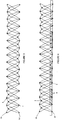
- the figure 3 illustrates an assembly of pairs of elements 2, 3 being formed by ball joints inserted in the openings 5A, 5A 'disposed at the ends of each element 2, 3.
- the assembly of the elements 2, 3 is arranged along the apron 1, on one side of the deck 1 in a plane substantially perpendicular to the axis of said hinges 4 and allowing a relative movement of the elements 2, 3 from a first position to a second position in said plane perpendicular to the axis of the hinges 4.
- an assembly of the elements 2, 3 is arranged along the deck 1, on either side of the deck 1.
- drive means 8 are arranged at one end of said structure, as illustrated in FIG. figure 5 , to adjust the apron 1 in length, the apron 1 bulging when pulled outward.
- the drive means 8 are arranged at both ends of said structure.
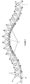
- the driving means 8 are arranged in such a way that when the means 8 come into action, they cause the pairs of elements 2, 3 to be assembled, said short portions of the elements 2, 3 being arranged on the upper part. pairs of elements 2, 3, arranged at the ends of the structure, while said short portions of the pairs of elements 2, 3 are arranged on the lower part of the pairs of elements 2, 3 arranged towards the center of the structure so as to cover the central part of the apron 1.
- the figure 5 illustrates a bridge in high position, with a domed central part, pairs of elements 2, 3 on the part central being reversed relative to pairs of elements 2, 3 disposed at each end of the bridge.
- the apron 1 consists of several movable transverse elements 9 arranged next to each other.
- the apron 1 consists of several bearings 9.
- the bearings 9 are juxtaposed, without space between two bearings 9, when the deck 1 is in the horizontal position.
- the movable transverse elements 9 are juxtaposed when the deck 1 is in the horizontal position.
- the figure 6 illustrates a structure seen from above in which pairs of elements 2, 3 are arranged on either side of the deck 1, said deck 1 consisting of bearings 9 juxtaposed and covered with a coating 7 of wood.
- the movable transverse elements 9 are slightly spaced relative to each other when the deck 1 is in the horizontal position.
- the figure 5 illustrates moving transverse elements 9 forming bearings articulated with respect to each other when the deck 1 is pulled in length, two bearings 9 being interconnected for example by a connecting arm, not shown.
- the central part of the deck 1 bombs without creating bearings 9.
- This variant provides a continuous surface that is passable for people with reduced mobility or vehicles.
- the apron is bomb but a bearing on two is inclined, the next being flat and forming a bearing.
- a rest stop is required at the top and bottom of each inclined plane regardless of the length. Different slopes can be arranged, ideally, the slope does not exceed 5%.
- the drive means 8 operable after construction of the structure is an actuator, of the jack type, which is arranged at one end of the deck 1.
- the figure 5 illustrates the cylinder on the left side of the deck 1.
- the elements 2, 3 constitute the framework of the railing and can be dressed in such a way as not to leave the structure accessible to all.
Landscapes
- Engineering & Computer Science (AREA)
- Architecture (AREA)
- Civil Engineering (AREA)
- Structural Engineering (AREA)
- Bridges Or Land Bridges (AREA)
- Road Paving Structures (AREA)
Claims (9)
- Nach der Errichtung mobiles und dynamisches Bauwerk, das zwei durch ein natürliches oder vom Menschen geschaffenes Hindernis getrennte Punkte verbindet, wobei das Bauwerk das dauernde Überqueren dieses Hindernisses ermöglicht, wobei das Bauwerk umfasst:- eine verformbare Fahrbahnplatte (1), die sich zwischen den beiden Punkten erstreckt,- einen Satz Elemente (2, 3) mit länglicher Form, die drei Öffnungen (5A, 5A', 5B) aufweisen, und zwar eine erste Öffnung (5A, 5A') an jedem Ende der Elemente (2, 3) und eine zweite dazwischenliegende Öffnung (5B), die zwischen den beiden ersten Öffnungen (5A, 5A') an den Enden der Elemente (2, 3) angeordnet ist, wobei die Öffnungen (5, 5A, 5A') Kugelgelenke aufnehmen, die dazu dienen, Scharniere (4) zu bilden, wobei jedes Element (2, 3) aus einem ersten kurzen Teil zwischen einer ersten Öffnung (5A) und der dazwischenliegenden Öffnung (5B) und aus einem zweiten längeren Teil zwischen der anderen ersten Öffnung(5A') und der dazwischenliegenden Öffnung (5B) besteht, wobei die Elemente (2, 3) paarweise drehbeweglich um ein mittleres Scharnier (4) angeordnet sind, das aus einem Kugelgelenk in den dazwischenliegenden Öffnungen (5B) von zwei Elementen (2, 3) besteht,gekennzeichnet durch:- eine Aneinanderreihung mehrerer Paare von Elementen (2, 3) durch Kugelgelenke, die in den Öffnungen (5A, 5A') an den Enden jedes Elements (2, 3) eingesetzt sind, wobei die Aneinanderreihung der Elemente (2, 3) entlang der Fahrbahnplatte (1) auf einer Seite oder zu beiden Seiten der Fahrbahnplatte (1) in einer im Wesentlichen senkrecht zur Achse der Scharniere (4) verlaufenden Ebene angeordnet ist und ein relatives Bewegen der Elemente (2, 3) von einer ersten Position zu einer zweiten Position ermöglicht, das in der senkrecht zur Achse der Scharniere (4) verlaufenden Ebene stattfindet,- wobei die kurzen Teile der Elemente (2, 3) am oberen Teil der an den Enden des Bauwerks Paare von angeordneten Elementen (2, 3) angeordnet sind, während die kurzen Teile der Elemente (2, 3) am unteren Teil der zur Mitte des Bauwerks hin angeordneten Paare von Elementen (2, 3) angeordnet sind, und- Antriebsmittel (8), die an einem oder an beiden Enden des Bauwerks angeordnet sind, um die Fahrbahnplatte (1) in der Länge anzupassen, wobei die Antriebsmittel (8) so gestaltet sind, dass sie, wenn die Mittel (8) in Gang gesetzt werden, die Aneinanderreihung der Paare von Elementen (2, 3) so antreiben, dass sich der mittlere Teil der Fahrbahnplatte (1) wölbt, wenn die beiden Enden des Bauwerks in die Länge gezogen werden, wobei die Antriebsmittel nach der Errichtung des Bauwerks so betätigbar sind, dass dieses mobil und dynamisch ist.
- Mobiles und dynamisches Überquerungsbauwerk nach Anspruch 1, wobei Elemente (2, 3) die Form eines ungleichseitigen Dreiecks von im Wesentlichen länglicher Form haben, das Öffnungen (5A, 5A', 5B) an den Scheitelpunkten (6) zum Aufnehmen der Kugelgelenke aufweist, wobei die dazwischenliegende Öffnung (5B) zum Scheitelpunkt des Dreiecks mit dem größten Winkel hin gelegen ist.
- Mobiles und dynamisches Überquerungsbauwerk nach einem der Ansprüche 1 oder 2, wobei die Fahrbahnplatte (1) aus mehreren mobilen Querelementen (9) besteht, die nahe beieinander angeordnet sind.
- Mobiles und dynamisches Überquerungsbauwerk nach Anspruch 3, wobei die mobilen Querelemente (9) nebeneinander liegen, wenn die Fahrbahnplatte (1) in der horizontalen Position ist.
- Mobiles und dynamisches Überquerungsbauwerk nach Anspruch 3, wobei die mobilen Querelemente (9) leicht voneinander abstehend sind, wenn die Fahrbahnplatte (1) in der horizontalen Position ist.
- Mobiles und dynamisches Überquerungsbauwerk nach Anspruch 3, wobei die mobilen Querelemente (9) Stufen bilden, die aneinander angegliedert sind, wenn die Fahrbahnplatte (1) in die Länge gezogen wird, wobei zwei Stufen (9) untereinander über mindestens einen Verbindungsarm verbunden sind.
- Mobiles und dynamisches Überquerungsbauwerk nach den Ansprüchen 1 und 2, wobei sich die Fahrbahnplatte (1) wölbt, ohne Stufen zu bilden, und eine durchgehende Fläche bildet.
- Mobiles und dynamisches Überquerungsbauwerk nach einem der vorhergehenden Ansprüche, wobei das Antriebsmittel (8) ein Zylinder oder eine Hydraulikspindel ist.
- Mobiles und dynamisches Überquerungsbauwerk nach einem der vorhergehenden Ansprüche, wobei die Elemente (2, 3) die Tragkonstruktion eines Brückengeländers auf einer Seite oder zu beiden Seiten der Fahrbahnplatte (1) bilden.
Applications Claiming Priority (2)
| Application Number | Priority Date | Filing Date | Title |
|---|---|---|---|
| CH01977/13A CH708897B1 (fr) | 2013-11-28 | 2013-11-28 | Ouvrage de franchissement mobile. |
| PCT/IB2014/001944 WO2015079293A1 (fr) | 2013-11-28 | 2014-09-29 | Ouvrage de franchissement mobile |
Publications (2)
| Publication Number | Publication Date |
|---|---|
| EP3074571A1 EP3074571A1 (de) | 2016-10-05 |
| EP3074571B1 true EP3074571B1 (de) | 2017-10-18 |
Family
ID=53188426
Family Applications (1)
| Application Number | Title | Priority Date | Filing Date |
|---|---|---|---|
| EP14798930.5A Not-in-force EP3074571B1 (de) | 2013-11-28 | 2014-09-29 | Mobile kreuzungsstruktur |
Country Status (7)
| Country | Link |
|---|---|
| US (1) | US10011961B2 (de) |
| EP (1) | EP3074571B1 (de) |
| CN (1) | CN105934548B (de) |
| AU (1) | AU2014356134B2 (de) |
| CH (1) | CH708897B1 (de) |
| NZ (1) | NZ720893A (de) |
| WO (1) | WO2015079293A1 (de) |
Families Citing this family (9)
| Publication number | Priority date | Publication date | Assignee | Title |
|---|---|---|---|---|
| WO2017066466A1 (en) | 2015-10-13 | 2017-04-20 | University Of Notre Dame Du Lac | Adjustable modules for variable depth structures |
| EP3551814A4 (de) | 2016-11-08 | 2020-10-28 | University of Notre Dame du Lac | Modulare trägerverbindung |
| CN106320160B (zh) * | 2016-11-15 | 2018-03-16 | 东南大学 | 一种可展拱桥结构 |
| CN106351109B (zh) * | 2016-11-15 | 2018-05-18 | 东南大学 | 一种折叠式拱桥结构 |
| CN106351110B (zh) * | 2016-11-15 | 2018-03-16 | 东南大学 | 一种上承式折叠桁架桥结构 |
| CN106498839B (zh) * | 2016-11-15 | 2018-05-18 | 东南大学 | 一种双向折叠桁架桥结构 |
| CN106702878B (zh) * | 2016-11-15 | 2018-07-27 | 东南大学 | 一种双向折叠桁架拱桥结构 |
| CN107956202B (zh) * | 2017-12-04 | 2024-05-31 | 江苏沪宁钢机股份有限公司 | 一种安全稳定的月牙桥及其安装工艺 |
| CN107905087A (zh) * | 2017-12-22 | 2018-04-13 | 贵州省水利水电勘测设计研究院 | 一种用于进水口的折叠式交通桥 |
Family Cites Families (13)
| Publication number | Priority date | Publication date | Assignee | Title |
|---|---|---|---|---|
| US175150A (en) * | 1876-03-21 | Improvement in flying-bridges | ||
| US2030262A (en) * | 1930-01-27 | 1936-02-11 | Maddock Thomas | Truss or bridge |
| GB534913A (en) | 1939-11-30 | 1941-03-21 | Nicholas Straussler | Improvements in or relating to collapsible bridges |
| US2697845A (en) * | 1951-06-18 | 1954-12-28 | Paul E Broner | Link structure |
| JPS6065806A (ja) * | 1984-07-20 | 1985-04-15 | 籏野 秀雄 | 可動式立体橋 |
| ES2168052B1 (es) | 2000-02-10 | 2003-10-16 | Sourdeau Alejandr Martin-Lunas | Viga enrollable |
| CN2554222Y (zh) * | 2001-05-31 | 2003-06-04 | 张赤兵 | 快速伸展和收缩的链架结构桥 |
| EP1636445A1 (de) * | 2003-05-27 | 2006-03-22 | Mark Panton | Stützvorrichtungen |
| JP4967117B2 (ja) * | 2005-09-14 | 2012-07-04 | 国立大学法人広島大学 | 構造体及びその主フレームの伸張・縮収装置 |
| FR2901817B1 (fr) * | 2006-05-31 | 2015-03-27 | Deschamps A & Fils Ets | Pont temporaire |
| US20080263791A1 (en) * | 2006-10-26 | 2008-10-30 | Thomas Edward Roberts | Heavy duty loading ramp for cargo transporting apparatus |
| US20080184502A1 (en) * | 2007-02-07 | 2008-08-07 | Thomas Edward Roberts | Handicap ramp for accessing and egressing transport vehicles |
| FR2945298B1 (fr) | 2009-05-06 | 2011-06-17 | Deschamps A & Fils Ets | Pont temporaire perfectionne |
-
2013
- 2013-11-28 CH CH01977/13A patent/CH708897B1/fr not_active IP Right Cessation
-
2014
- 2014-09-29 NZ NZ720893A patent/NZ720893A/en not_active IP Right Cessation
- 2014-09-29 WO PCT/IB2014/001944 patent/WO2015079293A1/fr not_active Ceased
- 2014-09-29 CN CN201480074286.6A patent/CN105934548B/zh not_active Expired - Fee Related
- 2014-09-29 US US15/039,856 patent/US10011961B2/en not_active Expired - Fee Related
- 2014-09-29 EP EP14798930.5A patent/EP3074571B1/de not_active Not-in-force
- 2014-09-29 AU AU2014356134A patent/AU2014356134B2/en not_active Ceased
Non-Patent Citations (1)
| Title |
|---|
| None * |
Also Published As
| Publication number | Publication date |
|---|---|
| US20160376754A1 (en) | 2016-12-29 |
| CH708897A1 (fr) | 2015-05-29 |
| US10011961B2 (en) | 2018-07-03 |
| AU2014356134A1 (en) | 2016-06-16 |
| WO2015079293A1 (fr) | 2015-06-04 |
| CN105934548A (zh) | 2016-09-07 |
| EP3074571A1 (de) | 2016-10-05 |
| CN105934548B (zh) | 2018-01-19 |
| AU2014356134B2 (en) | 2018-11-01 |
| NZ720893A (en) | 2016-10-28 |
| CH708897B1 (fr) | 2018-06-15 |
Similar Documents
| Publication | Publication Date | Title |
|---|---|---|
| EP3074571B1 (de) | Mobile kreuzungsstruktur | |
| EP2118408B1 (de) | Faltstruktur, die sich schnell auseinander- und wieder zusammenfalten lässt | |
| CA2714270C (fr) | Ancre de manutention d'elements de construction aux branches divergentes maintenues | |
| FR2589500A1 (fr) | Structure de couverture decouvrable d'un endroit quelconque, notamment d'une piscine | |
| CA2760743A1 (fr) | Pont temporaire perfectionne | |
| FR2987382A1 (fr) | Dispositif de couverture a elements de couverture coulissants | |
| FR2996238A1 (fr) | Garde-corps pour trappe d'ouverture au sol | |
| EP1334236B1 (de) | Ausziehbare Barriere auf Rollen mit manuell auszieh- und einziehbaren Schwenkelementen | |
| WO2007012706A1 (fr) | Barriere escamotable pour piscine, menageant un chemin de circulation securise | |
| EP3743660B1 (de) | Struktur von auf schienen einsetzbaren gelenkigen rahmen | |
| FR2602253A1 (fr) | Dispositif perfectionne de liaison de panneaux metalliques pour aire d'aerodrome | |
| EP2064111B1 (de) | Vorrichtung zur modifizierung der hülle eines schwimmkörpers und amphibienfahrzeug mit einer solchen vorrichtung | |
| FR2953546A1 (fr) | Abri de piscine a elements de toiture rotatifs | |
| CH630434A5 (fr) | Element pour batiment prefabrique et batiment realise a l'aide de cet element. | |
| FR2528895A1 (fr) | Element de plancher modulaire juxtaposable et gerbable | |
| FR2698650A1 (fr) | Passerelle pour le franchissement d'obstacle. | |
| EP2489809B1 (de) | Verfahren zur Herstellung eines Strukturelements, und so hergestellte Elemente | |
| FR2937026A1 (fr) | Dispositif elevateur et procede de fabrication correspondant | |
| EP2672039B1 (de) | Hubvorrichtung für Element eines Schutzdachs für Becken | |
| FR3074509A1 (fr) | Element de couverture, abri et procede associe | |
| EP2292875A1 (de) | Schwimmbadabdeckung | |
| WO2013144368A1 (fr) | Abri comprenant des elements de toiture ayant une couverture composee modules coulissants | |
| WO2005031089A2 (fr) | Barriere a claire-voie escamotable pour piscine. | |
| FR3020650A1 (fr) | Abri de piscine a modules telescopiques comprenant un systeme de verrouillage des modules | |
| FR3001475A1 (fr) | Abri repliable comprenant une pluralite d'elements de toiture, et au moins un dispositif d'ancrage au sol d'au moins un des elements de toiture |
Legal Events
| Date | Code | Title | Description |
|---|---|---|---|
| PUAI | Public reference made under article 153(3) epc to a published international application that has entered the european phase |
Free format text: ORIGINAL CODE: 0009012 |
|
| 17P | Request for examination filed |
Effective date: 20150731 |
|
| AK | Designated contracting states |
Kind code of ref document: A1 Designated state(s): AL AT BE BG CH CY CZ DE DK EE ES FI FR GB GR HR HU IE IS IT LI LT LU LV MC MK MT NL NO PL PT RO RS SE SI SK SM TR |
|
| AX | Request for extension of the european patent |
Extension state: BA ME |
|
| DAX | Request for extension of the european patent (deleted) | ||
| GRAP | Despatch of communication of intention to grant a patent |
Free format text: ORIGINAL CODE: EPIDOSNIGR1 |
|
| STAA | Information on the status of an ep patent application or granted ep patent |
Free format text: STATUS: GRANT OF PATENT IS INTENDED |
|
| INTG | Intention to grant announced |
Effective date: 20170509 |
|
| GRAS | Grant fee paid |
Free format text: ORIGINAL CODE: EPIDOSNIGR3 |
|
| GRAA | (expected) grant |
Free format text: ORIGINAL CODE: 0009210 |
|
| STAA | Information on the status of an ep patent application or granted ep patent |
Free format text: STATUS: THE PATENT HAS BEEN GRANTED |
|
| AK | Designated contracting states |
Kind code of ref document: B1 Designated state(s): AL AT BE BG CH CY CZ DE DK EE ES FI FR GB GR HR HU IE IS IT LI LT LU LV MC MK MT NL NO PL PT RO RS SE SI SK SM TR |
|
| REG | Reference to a national code |
Ref country code: GB Ref legal event code: FG4D Free format text: NOT ENGLISH |
|
| REG | Reference to a national code |
Ref country code: CH Ref legal event code: EP |
|
| REG | Reference to a national code |
Ref country code: AT Ref legal event code: REF Ref document number: 938072 Country of ref document: AT Kind code of ref document: T Effective date: 20171115 Ref country code: IE Ref legal event code: FG4D Free format text: LANGUAGE OF EP DOCUMENT: FRENCH |
|
| REG | Reference to a national code |
Ref country code: DE Ref legal event code: R096 Ref document number: 602014016082 Country of ref document: DE |
|
| REG | Reference to a national code |
Ref country code: CH Ref legal event code: NV Representative=s name: GRIFFES CONSULTING SA, CH |
|
| REG | Reference to a national code |
Ref country code: NL Ref legal event code: MP Effective date: 20171018 |
|
| REG | Reference to a national code |
Ref country code: LT Ref legal event code: MG4D |
|
| REG | Reference to a national code |
Ref country code: AT Ref legal event code: MK05 Ref document number: 938072 Country of ref document: AT Kind code of ref document: T Effective date: 20171018 |
|
| PG25 | Lapsed in a contracting state [announced via postgrant information from national office to epo] |
Ref country code: NL Free format text: LAPSE BECAUSE OF FAILURE TO SUBMIT A TRANSLATION OF THE DESCRIPTION OR TO PAY THE FEE WITHIN THE PRESCRIBED TIME-LIMIT Effective date: 20171018 |
|
| PG25 | Lapsed in a contracting state [announced via postgrant information from national office to epo] |
Ref country code: LT Free format text: LAPSE BECAUSE OF FAILURE TO SUBMIT A TRANSLATION OF THE DESCRIPTION OR TO PAY THE FEE WITHIN THE PRESCRIBED TIME-LIMIT Effective date: 20171018 Ref country code: ES Free format text: LAPSE BECAUSE OF FAILURE TO SUBMIT A TRANSLATION OF THE DESCRIPTION OR TO PAY THE FEE WITHIN THE PRESCRIBED TIME-LIMIT Effective date: 20171018 Ref country code: NO Free format text: LAPSE BECAUSE OF FAILURE TO SUBMIT A TRANSLATION OF THE DESCRIPTION OR TO PAY THE FEE WITHIN THE PRESCRIBED TIME-LIMIT Effective date: 20180118 Ref country code: FI Free format text: LAPSE BECAUSE OF FAILURE TO SUBMIT A TRANSLATION OF THE DESCRIPTION OR TO PAY THE FEE WITHIN THE PRESCRIBED TIME-LIMIT Effective date: 20171018 Ref country code: SE Free format text: LAPSE BECAUSE OF FAILURE TO SUBMIT A TRANSLATION OF THE DESCRIPTION OR TO PAY THE FEE WITHIN THE PRESCRIBED TIME-LIMIT Effective date: 20171018 |
|
| PG25 | Lapsed in a contracting state [announced via postgrant information from national office to epo] |
Ref country code: IS Free format text: LAPSE BECAUSE OF FAILURE TO SUBMIT A TRANSLATION OF THE DESCRIPTION OR TO PAY THE FEE WITHIN THE PRESCRIBED TIME-LIMIT Effective date: 20180218 Ref country code: BG Free format text: LAPSE BECAUSE OF FAILURE TO SUBMIT A TRANSLATION OF THE DESCRIPTION OR TO PAY THE FEE WITHIN THE PRESCRIBED TIME-LIMIT Effective date: 20180118 Ref country code: LV Free format text: LAPSE BECAUSE OF FAILURE TO SUBMIT A TRANSLATION OF THE DESCRIPTION OR TO PAY THE FEE WITHIN THE PRESCRIBED TIME-LIMIT Effective date: 20171018 Ref country code: AT Free format text: LAPSE BECAUSE OF FAILURE TO SUBMIT A TRANSLATION OF THE DESCRIPTION OR TO PAY THE FEE WITHIN THE PRESCRIBED TIME-LIMIT Effective date: 20171018 Ref country code: RS Free format text: LAPSE BECAUSE OF FAILURE TO SUBMIT A TRANSLATION OF THE DESCRIPTION OR TO PAY THE FEE WITHIN THE PRESCRIBED TIME-LIMIT Effective date: 20171018 Ref country code: HR Free format text: LAPSE BECAUSE OF FAILURE TO SUBMIT A TRANSLATION OF THE DESCRIPTION OR TO PAY THE FEE WITHIN THE PRESCRIBED TIME-LIMIT Effective date: 20171018 Ref country code: GR Free format text: LAPSE BECAUSE OF FAILURE TO SUBMIT A TRANSLATION OF THE DESCRIPTION OR TO PAY THE FEE WITHIN THE PRESCRIBED TIME-LIMIT Effective date: 20180119 |
|
| REG | Reference to a national code |
Ref country code: DE Ref legal event code: R097 Ref document number: 602014016082 Country of ref document: DE |
|
| PG25 | Lapsed in a contracting state [announced via postgrant information from national office to epo] |
Ref country code: CZ Free format text: LAPSE BECAUSE OF FAILURE TO SUBMIT A TRANSLATION OF THE DESCRIPTION OR TO PAY THE FEE WITHIN THE PRESCRIBED TIME-LIMIT Effective date: 20171018 Ref country code: DK Free format text: LAPSE BECAUSE OF FAILURE TO SUBMIT A TRANSLATION OF THE DESCRIPTION OR TO PAY THE FEE WITHIN THE PRESCRIBED TIME-LIMIT Effective date: 20171018 Ref country code: EE Free format text: LAPSE BECAUSE OF FAILURE TO SUBMIT A TRANSLATION OF THE DESCRIPTION OR TO PAY THE FEE WITHIN THE PRESCRIBED TIME-LIMIT Effective date: 20171018 Ref country code: SK Free format text: LAPSE BECAUSE OF FAILURE TO SUBMIT A TRANSLATION OF THE DESCRIPTION OR TO PAY THE FEE WITHIN THE PRESCRIBED TIME-LIMIT Effective date: 20171018 |
|
| PLBE | No opposition filed within time limit |
Free format text: ORIGINAL CODE: 0009261 |
|
| STAA | Information on the status of an ep patent application or granted ep patent |
Free format text: STATUS: NO OPPOSITION FILED WITHIN TIME LIMIT |
|
| PG25 | Lapsed in a contracting state [announced via postgrant information from national office to epo] |
Ref country code: SM Free format text: LAPSE BECAUSE OF FAILURE TO SUBMIT A TRANSLATION OF THE DESCRIPTION OR TO PAY THE FEE WITHIN THE PRESCRIBED TIME-LIMIT Effective date: 20171018 Ref country code: RO Free format text: LAPSE BECAUSE OF FAILURE TO SUBMIT A TRANSLATION OF THE DESCRIPTION OR TO PAY THE FEE WITHIN THE PRESCRIBED TIME-LIMIT Effective date: 20171018 Ref country code: PL Free format text: LAPSE BECAUSE OF FAILURE TO SUBMIT A TRANSLATION OF THE DESCRIPTION OR TO PAY THE FEE WITHIN THE PRESCRIBED TIME-LIMIT Effective date: 20171018 |
|
| REG | Reference to a national code |
Ref country code: FR Ref legal event code: PLFP Year of fee payment: 5 |
|
| 26N | No opposition filed |
Effective date: 20180719 |
|
| PG25 | Lapsed in a contracting state [announced via postgrant information from national office to epo] |
Ref country code: MT Free format text: LAPSE BECAUSE OF FAILURE TO SUBMIT A TRANSLATION OF THE DESCRIPTION OR TO PAY THE FEE WITHIN THE PRESCRIBED TIME-LIMIT Effective date: 20171018 |
|
| PG25 | Lapsed in a contracting state [announced via postgrant information from national office to epo] |
Ref country code: SI Free format text: LAPSE BECAUSE OF FAILURE TO SUBMIT A TRANSLATION OF THE DESCRIPTION OR TO PAY THE FEE WITHIN THE PRESCRIBED TIME-LIMIT Effective date: 20171018 |
|
| PG25 | Lapsed in a contracting state [announced via postgrant information from national office to epo] |
Ref country code: MC Free format text: LAPSE BECAUSE OF FAILURE TO SUBMIT A TRANSLATION OF THE DESCRIPTION OR TO PAY THE FEE WITHIN THE PRESCRIBED TIME-LIMIT Effective date: 20171018 |
|
| REG | Reference to a national code |
Ref country code: BE Ref legal event code: MM Effective date: 20180930 |
|
| REG | Reference to a national code |
Ref country code: IE Ref legal event code: MM4A |
|
| PG25 | Lapsed in a contracting state [announced via postgrant information from national office to epo] |
Ref country code: LU Free format text: LAPSE BECAUSE OF NON-PAYMENT OF DUE FEES Effective date: 20180929 |
|
| PG25 | Lapsed in a contracting state [announced via postgrant information from national office to epo] |
Ref country code: IE Free format text: LAPSE BECAUSE OF NON-PAYMENT OF DUE FEES Effective date: 20180929 |
|
| PG25 | Lapsed in a contracting state [announced via postgrant information from national office to epo] |
Ref country code: BE Free format text: LAPSE BECAUSE OF NON-PAYMENT OF DUE FEES Effective date: 20180930 |
|
| PGFP | Annual fee paid to national office [announced via postgrant information from national office to epo] |
Ref country code: FR Payment date: 20190927 Year of fee payment: 6 |
|
| PGFP | Annual fee paid to national office [announced via postgrant information from national office to epo] |
Ref country code: GB Payment date: 20190927 Year of fee payment: 6 |
|
| PGFP | Annual fee paid to national office [announced via postgrant information from national office to epo] |
Ref country code: DE Payment date: 20190927 Year of fee payment: 6 Ref country code: CH Payment date: 20190923 Year of fee payment: 6 |
|
| PGFP | Annual fee paid to national office [announced via postgrant information from national office to epo] |
Ref country code: IT Payment date: 20190930 Year of fee payment: 6 |
|
| PG25 | Lapsed in a contracting state [announced via postgrant information from national office to epo] |
Ref country code: TR Free format text: LAPSE BECAUSE OF FAILURE TO SUBMIT A TRANSLATION OF THE DESCRIPTION OR TO PAY THE FEE WITHIN THE PRESCRIBED TIME-LIMIT Effective date: 20171018 |
|
| PG25 | Lapsed in a contracting state [announced via postgrant information from national office to epo] |
Ref country code: PT Free format text: LAPSE BECAUSE OF FAILURE TO SUBMIT A TRANSLATION OF THE DESCRIPTION OR TO PAY THE FEE WITHIN THE PRESCRIBED TIME-LIMIT Effective date: 20171018 |
|
| PG25 | Lapsed in a contracting state [announced via postgrant information from national office to epo] |
Ref country code: CY Free format text: LAPSE BECAUSE OF FAILURE TO SUBMIT A TRANSLATION OF THE DESCRIPTION OR TO PAY THE FEE WITHIN THE PRESCRIBED TIME-LIMIT Effective date: 20171018 Ref country code: MK Free format text: LAPSE BECAUSE OF NON-PAYMENT OF DUE FEES Effective date: 20171018 Ref country code: HU Free format text: LAPSE BECAUSE OF FAILURE TO SUBMIT A TRANSLATION OF THE DESCRIPTION OR TO PAY THE FEE WITHIN THE PRESCRIBED TIME-LIMIT; INVALID AB INITIO Effective date: 20140929 |
|
| PG25 | Lapsed in a contracting state [announced via postgrant information from national office to epo] |
Ref country code: AL Free format text: LAPSE BECAUSE OF FAILURE TO SUBMIT A TRANSLATION OF THE DESCRIPTION OR TO PAY THE FEE WITHIN THE PRESCRIBED TIME-LIMIT Effective date: 20171018 |
|
| REG | Reference to a national code |
Ref country code: DE Ref legal event code: R119 Ref document number: 602014016082 Country of ref document: DE |
|
| REG | Reference to a national code |
Ref country code: CH Ref legal event code: PL |
|
| GBPC | Gb: european patent ceased through non-payment of renewal fee |
Effective date: 20200929 |
|
| PG25 | Lapsed in a contracting state [announced via postgrant information from national office to epo] |
Ref country code: FR Free format text: LAPSE BECAUSE OF NON-PAYMENT OF DUE FEES Effective date: 20200930 Ref country code: DE Free format text: LAPSE BECAUSE OF NON-PAYMENT OF DUE FEES Effective date: 20210401 |
|
| PG25 | Lapsed in a contracting state [announced via postgrant information from national office to epo] |
Ref country code: CH Free format text: LAPSE BECAUSE OF NON-PAYMENT OF DUE FEES Effective date: 20200930 Ref country code: LI Free format text: LAPSE BECAUSE OF NON-PAYMENT OF DUE FEES Effective date: 20200930 Ref country code: GB Free format text: LAPSE BECAUSE OF NON-PAYMENT OF DUE FEES Effective date: 20200929 |
|
| PG25 | Lapsed in a contracting state [announced via postgrant information from national office to epo] |
Ref country code: IT Free format text: LAPSE BECAUSE OF NON-PAYMENT OF DUE FEES Effective date: 20200929 |