EP2489809B1 - Verfahren zur Herstellung eines Strukturelements, und so hergestellte Elemente - Google Patents
Verfahren zur Herstellung eines Strukturelements, und so hergestellte Elemente Download PDFInfo
- Publication number
- EP2489809B1 EP2489809B1 EP12002843.6A EP12002843A EP2489809B1 EP 2489809 B1 EP2489809 B1 EP 2489809B1 EP 12002843 A EP12002843 A EP 12002843A EP 2489809 B1 EP2489809 B1 EP 2489809B1
- Authority
- EP
- European Patent Office
- Prior art keywords
- plates
- spacers
- plate
- support
- fact
- Prior art date
- Legal status (The legal status is an assumption and is not a legal conclusion. Google has not performed a legal analysis and makes no representation as to the accuracy of the status listed.)
- Active
Links
- 238000000034 method Methods 0.000 title claims description 25
- 238000004519 manufacturing process Methods 0.000 title description 9
- 125000006850 spacer group Chemical group 0.000 claims description 15
- 230000000284 resting effect Effects 0.000 claims description 7
- 239000002023 wood Substances 0.000 claims description 3
- 238000009434 installation Methods 0.000 claims description 2
- 230000000670 limiting effect Effects 0.000 claims description 2
- 238000000926 separation method Methods 0.000 claims description 2
- 238000010008 shearing Methods 0.000 claims description 2
- 238000010276 construction Methods 0.000 description 9
- 238000005452 bending Methods 0.000 description 3
- 239000000463 material Substances 0.000 description 3
- 230000002829 reductive effect Effects 0.000 description 2
- 230000002441 reversible effect Effects 0.000 description 2
- HCHKCACWOHOZIP-UHFFFAOYSA-N Zinc Chemical compound [Zn] HCHKCACWOHOZIP-UHFFFAOYSA-N 0.000 description 1
- 239000004567 concrete Substances 0.000 description 1
- 230000000694 effects Effects 0.000 description 1
- 229940082150 encore Drugs 0.000 description 1
- 238000005192 partition Methods 0.000 description 1
- 230000001681 protective effect Effects 0.000 description 1
- 230000001105 regulatory effect Effects 0.000 description 1
- 239000011150 reinforced concrete Substances 0.000 description 1
- 239000004576 sand Substances 0.000 description 1
- 238000007789 sealing Methods 0.000 description 1
- 239000010454 slate Substances 0.000 description 1
- 229920002994 synthetic fiber Polymers 0.000 description 1
- 239000011701 zinc Substances 0.000 description 1
- 229910052725 zinc Inorganic materials 0.000 description 1
Images

Classifications
-
- E—FIXED CONSTRUCTIONS
- E04—BUILDING
- E04C—STRUCTURAL ELEMENTS; BUILDING MATERIALS
- E04C3/00—Structural elongated elements designed for load-supporting
- E04C3/02—Joists; Girders, trusses, or trusslike structures, e.g. prefabricated; Lintels; Transoms; Braces
- E04C3/12—Joists; Girders, trusses, or trusslike structures, e.g. prefabricated; Lintels; Transoms; Braces of wood, e.g. with reinforcements, with tensioning members
- E04C3/16—Joists; Girders, trusses, or trusslike structures, e.g. prefabricated; Lintels; Transoms; Braces of wood, e.g. with reinforcements, with tensioning members with apertured web, e.g. trusses
-
- E—FIXED CONSTRUCTIONS
- E04—BUILDING
- E04B—GENERAL BUILDING CONSTRUCTIONS; WALLS, e.g. PARTITIONS; ROOFS; FLOORS; CEILINGS; INSULATION OR OTHER PROTECTION OF BUILDINGS
- E04B7/00—Roofs; Roof construction with regard to insulation
- E04B7/08—Vaulted roofs
-
- E—FIXED CONSTRUCTIONS
- E04—BUILDING
- E04C—STRUCTURAL ELEMENTS; BUILDING MATERIALS
- E04C3/00—Structural elongated elements designed for load-supporting
- E04C3/02—Joists; Girders, trusses, or trusslike structures, e.g. prefabricated; Lintels; Transoms; Braces
- E04C3/12—Joists; Girders, trusses, or trusslike structures, e.g. prefabricated; Lintels; Transoms; Braces of wood, e.g. with reinforcements, with tensioning members
- E04C3/122—Laminated
-
- E—FIXED CONSTRUCTIONS
- E04—BUILDING
- E04C—STRUCTURAL ELEMENTS; BUILDING MATERIALS
- E04C3/00—Structural elongated elements designed for load-supporting
- E04C3/38—Arched girders or portal frames
- E04C3/42—Arched girders or portal frames of wood, e.g. units for rafter roofs
Definitions
- the subject of the invention is a method for producing a structural element which can be applied to the construction of buildings.
- the invention allows, in general, all kinds of elongated structural elements intended to rest on two spaced apart supports, such as beams or posts.
- the roof of a building normally includes a covering, for example of slate, tiles or other materials, resting on a frame supported on the walls.
- the elements of the frame must therefore have a span corresponding to the distance between the supports. It is interesting, for medium spans, for example 10 to 12 meters, to use structural elements light enough to avoid the use of heavy lifting equipment.
- the frame of a detached house can consist of prefabricated wooden trusses, which can be installed by a few men.
- Such relatively light structural elements form kinds of curved trusses making it possible, for example, to produce a slightly vaulted roof.
- the curvature of this arch depends on the resistance to bending of the wooden slats.
- they must be supported at their ends on a tie rod which extends between the supports, across the covered space.
- the technique known as "glued-laminated" makes it possible to produce wooden structural elements whose profile can be varied, for example for the production of a curved roof, possibly with reverse curvature.
- the glulam technique requires relatively large and expensive equipment and, therefore, is only used in practice for industrial or commercial buildings or, for example, motorway toll stations but is not economically applicable to the construction of medium-sized buildings.
- the invention relates to a new type of wooden frame elements which can have any desired shape, for example curved, such a method, particularly simple and economical, being profitable even for the production of elements of low or medium range, for example for the construction of individual houses.
- the invention therefore relates, in general, to a method according to claim 1 of a structural element extending along a longitudinal axis over a certain length and consisting of at least two thin plates joined by rows spaced spacers which are interposed between two neighboring plates and fixed respectively on their opposite faces, so as to form an integral assembly capable of resting on two spaced apart supports.
- a first plate cut in a shape desired for the element, with two longitudinal sides and two transverse sides, is applied and fixed, by an internal face, on a first series of battens distributed over a flat support, then the whole of this plate provided with cleats on its internal face is turned over and applied, by its opposite smooth external face, to a rigid support having a desired profile for the element to be produced, a second assembly comprising a second plate provided with a second series of cleats is then produced in the same way on the flat support then turned over, applied and fixed on the first series of cleats of the first plate taking the form of the rigid support and so on until at laying and fixing on a last series of battens, an external closure plate not provided with battens, in order to produce an element which is then moved away from the support while retaining the shape of the latter.
- the various plates thus assembled are cut so as to present the same external profile with two longitudinal sides, having a desired profile and said longitudinal sides are aligned during the assembly of the plates, along two lateral faces and, when the place of the element thus produced, the plates thereof are arranged vertically and rest on edge on the supports, so that the element has two faces, respectively lower and upper having a desired profile, the number of plates, their thickness and the thickness of the cleats being determined so as to give the element the desired resistance, while limiting its own weight.
- Each plate, as well as the cleats can be made of a homogeneous, resistant and relatively flexible material, such as wood or the like, and the spaced cleats are fixed by nailing or screwing on the plates between which they are interposed, so as to form a united and resistant whole.
- each plate consists of at least two superposed layers each consisting of several sheets placed one after the other in the longitudinal direction of the element, the transverse joints between the ends adjacent consecutive sheets being offset longitudinally from one layer to another.
- the two external plates may have a greater thickness than the intermediate plate or plates.
- the two series of cleats fixed respectively on the two faces of the same plate are preferably offset longitudinally relative to each other.
- the rigid support on which the various plates are successively applied after turning has a curved application face in the form of a regulated surface and the cleats are placed so as to be arranged, after application on said curved face , according to the generators thereof, so that the assembly of each plate with its cleats remain flexible enough to take the form of the rigid support which thus constitutes a template for the production of an element having a desired curved profile.
- the rigid support on which the various plates are applied successively, after turning over has a flat application face in order to produce, after fixing the closure plate, a rectilinear element limited by two flat faces.
- the invention also presents other possibilities and makes it possible, for example, to produce a building frame comprising a set of beams for supporting a floor or a roof resting on vertical posts, in which the beams and the posts consist of laminated elements produced by the method according to the invention and assembled in such a way that the plates constituting a beam overlap between the plates constituting a post, the assembly being secured by bolting.
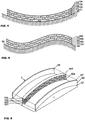
- FIG. 1 there is shown, in perspective, a structural element such as a beam 1, intended to rest on two spaced apart supports A 1 , A 2 represented symbolically and which can be, for example, two walls of a building or two beams transverse resting on pillars.
- a structural element such as a beam 1
- a 2 represented symbolically and which can be, for example, two walls of a building or two beams transverse resting on pillars.
- This beam 1 consists, in the example shown, of four superimposed plates 10, separated by three rows of battens 2. Its thickness e depends on the number of plates 10, their thickness e 1 and the thickness e 2 of the battens 2.
- This thickness e is determined to give the beam 1 the necessary resistance, taking into account the span L between the supports A 1 , A 2 and the load to be supported.
- the length L 1 of the beam is at least equal to the span L but its width depends essentially on the weight that one wishes to give to the beam, taking into account the lifting means available.
- the wooden beam thus made up of several separated sheets, can have a moment of inertia large enough to give it the desired resistance, while having a weight limited enough to allow the handling and installation by a few men, even for a range of several meters.
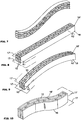
- Such a beam can be produced very simply by means of the method according to the invention which will now be described with reference to figures 2,3 , and 4 .
- a first series of cleats 21 are distributed on a fixed flat support 3, then a first plate 101 is applied, by an internal face 15, to this series of cleats and fixed to each of them, by nails or screws 4 which are easily placed on the side of its external face 14.
- this plate 101 provided with cleats 21 is turned over and applied to a rigid support 3 ′ having an upper face 31 which has the desired profile for the element.
- this profile is cylindrical and the cleats 21 distributed on the flat support 3 are parallel to each other, the plate 101 having a rectangular shape with a longitudinal axis perpendicular to the direction of the cleats 21. Therefore, if this longitudinal axis is parallel to the axis of the cylindrical surface31, the cleats 21 are parallel to the generatrices of the cylinder and the assembly of the thin plate 101 with its cleats 21 remains flexible enough to take the shape of this surface 31.
- a second plate 102 provided with cleats 22 is produced in the same way on the planar support 3 but the cleats 22 are offset by half a step relative to the cleats 21 of the first plate101.
- This second plate 102 is also turned over and applied by its external face 142 to the upper faces of the cleats 21 of the first plate and fixed to the latter by nails 42 or screws which are laid and fixed easily on the plate 102 due to the offset of the battens.
- a third plate 103 is produced in the same way on the flat support 3 but it is provided with cleats 23 offset by a half-step relative to the cleats 22 of the second plate 102 and, consequently, in the same position as the cleats 21 of the first plate 101.
- This third plate 103 is turned over and fixed on the cleats 22 of the second plate 102 by nails or screws 43.
- An external plate 104 not provided with cleats is then applied and fixed by nails or screws 44 on the cleats 23 of the third plate 103.
- a laminated element with four layers 101, 102, 103, 104 was thus produced, separated by three series of battens 21, 22, 23, of the type shown in the figure 4 , by simply using wooden plates and cleats fastened by nails or screws.
- each set of a thin plate 10 provided on one face with battens 2 is flexible enough to take the shape of the template 3 'as soon as the battens are directed along the generatrices of the application surface 31.
- the connection made by nails or screws withstands very well the detachment and shearing forces and the element 1 thus formed retains its shape when it is moved away from the support 3 ′ and even has a excellent resistance to bending which essentially depends on the thickness e of the element.
- the number of plates, their thicknesses and the thickness of the cleats can be determined so as to obtain the desired resistance, taking into account the range between supports, without excessively increasing the weight of the element 1.
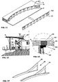
- such a method makes it possible to give the element a straight or curved shape, with a curvature turned upwards or downwards, or even with a double curvature, as shown in the examples of figures 4, 5 , 7 .
- the structural elements thus produced consist only of wooden plates and cleats which can be cut to size and brought to the site to be assembled manually. It suffices, in fact, to produce on the site, for example in concrete, a flat slab 3 for fixing the plates to the cleats and a rigid support 3 ′ with an assembly face 31 having the desired profile, to superimpose and fix one on the other, the plates fitted with cleats.
- such a beam may have a weight of the order of 100 kg for a span of 7 to 8 meters, while having a relatively high resistance to bending, due to its thickness and the connection between the plates 10 and cleats 2.
- the width of the element must be sufficient to give it a certain base and distribute the load on the supports, for example on a sand plate formed at the top of a wall or a partition. , as shown on the figure 12 .
- An element of small width relative to its range can constitute a support beam for a floor or a roof.
- this width can be arbitrary and, for example, can cover a large area.
- Such an element can then constitute a floor slab or a roofing element of vaulted form.
- the upper face 501 may be covered with a sheet forming a sealing skin, for example made of zinc or of synthetic material.
- a sheet forming a sealing skin for example made of zinc or of synthetic material.
- its lateral faces 56 can be closed by walls having edges 57, 57 ′ cut according to the profile of the curved plates 501, 504.
- the figure 12 shows a single house with a roof 6.
- the beams 6 for supporting the roof can be placed on a plate 61 resting on the posts 60.
- the number of plates and row of battens can be varied, depending on the range.
- the rigid support on which the plates provided with cleats are assembled has a flat application face on which the plates are placed flat.
- the flexural strength of the beam also placed on edge can be increased by simply playing on the width of the plates 10, that is to say the height of the beam, which determines the moment of inertia of this one.
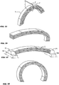
- the template 3 'used to assemble a curved beam of the type of Figures 4 and 5 could be achieved in the same way, by superimposing several flat plates separated by cleats and whose longitudinal sides 18 are cut according to the profile to be given to the element produced, as before, by assembling plates 101, 102 provided with cleats 21, 22.
- the figure 10 shows such an element intended to be placed on edge but whose vertical side faces are curved, for example to produce a facade element with a projection of the bow-window type.
- the lower and upper faces 17, 17 'of the element are not necessarily planar, the longitudinal sides 16, 16' of the plates 10 can be cut according to a desired profile.
- laminated elements with reverse curvature of the type of figure 7 , allow to realize a seated dog 65. But, for this, we can also use elements assembled flat and placed on edge, as shown on the figure 14 .
- FIG. 17 shows the mounting of a slightly vaulted element 1, with inclined end faces bearing on abutment parts 71 mounted on side walls 72 which oppose the separation of the ends under the effect of the applied loads.
- the laying lines of the elements need not necessarily be parallel, the process allowing the production of any non-cylindrical set surface.
- the cleats can be arranged so as to be parallel to the corresponding generatrices of the template, the plates thus produced remain flexible enough to be applied to the template which may have the profile of a portion of a cone, d hyperboloid or hyperbolic paraboloid with two lines of pose making between them a certain angle.
- the method according to the invention makes it possible to produce such structural elements on the site of the construction site with very reduced equipment since it suffices to have a flat slab for fixing the plates to the battens and a rigid support having the desired shape, for superimposing and fixing these plates one on the other, such supports that can be produced on site in reinforced concrete. It will therefore be sufficient to bring wooden plates and cleats to the site, all the rest of the construction being carried out on site.
- the invention gives great freedom of choice, not only for the design of a house but also for the construction site which can possibly be difficult to access for vehicles.
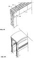
- the rectilinear elements of the type shown in the figure 8 can be arranged vertically so as to constitute posts or pillars, the laminated structure of the various elements making it possible to assemble them easily in the manner shown on the figure 19 .
- the plates 10 and the cleats 21 of a horizontal element 1 have, respectively, the same thicknesses that the cleats 21 'and the plates 10' of a vertical element 1 ', their ends can be threaded one inside the other and be fixed by bolts 19 or other means of assembly, in order to constitute a gantry structure.
Landscapes
- Engineering & Computer Science (AREA)
- Architecture (AREA)
- Civil Engineering (AREA)
- Structural Engineering (AREA)
- Life Sciences & Earth Sciences (AREA)
- Wood Science & Technology (AREA)
- Physics & Mathematics (AREA)
- Electromagnetism (AREA)
- Rod-Shaped Construction Members (AREA)
- Forms Removed On Construction Sites Or Auxiliary Members Thereof (AREA)
- Floor Finish (AREA)
- Conveying And Assembling Of Building Elements In Situ (AREA)
Claims (7)
- Verfahren zur Herstellung eines Strukturelements, das sich entlang einer Längsachse über eine bestimmte Länge (L) erstreckt und aus mindestens zwei dünnen Platten besteht, die durch Reihen von beabstandete Abstandleiste verbunden sind, wobei diese Abstandleiste zwischen zwei benachbarten Platten (101, 102) angeordnet und jeweils auf ihren Stirnflächen (13, 14) befestigt sind, um eine solidarische Anordnung zu bilden, die auf zwei beabstandeten Stützen (A1, A2) ruhen kann, dadurch gekennzeichnet, dass eine, in eine gewünschte Form für das Element (1) mit zwei Längsseiten und zwei Querseiten geschnittene erste Platte (101), auf eine erste Reihe von auf einem flachen Halter (3) verteilte Leisten (21) aufgebracht und durch eine Innenfläche (15) fixiert wird, dass diese mit Leisten (21) auf ihrer Innenfläche (15) ausgestattene gesamte Platte (101) umgedreht und durch ihre gegenüberliegende glatte Außenfläche (14) auf einer Anlegungsfläche (31) eines starren Halters (3') angelehnt wird, dass eine zweite Anordnung, die eine zweite mit einer zweiten Reihe von Leisten (22) ausgestattene Platte (102) umfasst, auf die gleiche Weise auf dem flachen Halter (3) hergestellt wird und dann umgedreht und auf die erste Reihe von Leisten (21) der ersten Platte (101) angelegt und fixiert wird, wobei diese zweite platte (102) die Form des starren Halters (3') nimmt, und so weiter, bis zur Installation und Fixierung auf einer letzten Reihe von Leisten (23) von einer nicht bei Leisten ausgestattenen äußeren Schließplatte (104), um ein Element (1) herzustellen, das dann unter Beibehaltung seiner Form von dem starren Halter (3') entfernt wird, wobei die so zusammengesetzten verschiedenen Platten (101,102... 104) so geschnitten werden, dass sie einen gleichen Außenprofil mit zwei Längsseiten (16, 16') aufweisen, wobei diese Längsseiten (16, 16') einen gewünschten Profil haben und während der Montage der Platten entlang zwei Seitenflächen (17, 17') ausgerichtet werden und wobei, wenn das so hergestellte Element (1) aufgestellt wird, die Platten (101, 102....) derselben vertical auf Kante angeordnet sind und auf den Stützen (A1, A2) aufliegen, so dass das Element (1) zwei Flächen aufweist, jeweils unten (17) und oben (17') mit einem gewünschten Profil, wobei die Anzahl der Platten, ihre Dicke und die Dicke der Leisten so bestimmt werden, dass das Element (1) die gewünschte Festigkeit erhält und gleichzeitig sein Eigengewicht begrenzt wird.
- Verfahren nach Anspruch 1 dadurch gekennzeichnet, dass der starre Halter (3'), auf dem die verschiedenen Platten (101,102... 104) nach Umdrehung nach und nach angewendet werden, eine ebene Anlegungsseite (31) vorstellt, um nach Befestigung der Schliessplatte (104), ein bei zwei ebener Seiten begrenztes geradliniges Element zu bilden.
- Verfahren nach Anspruch 2 dadurch gekennzeichnet, daß einen gleichen ebenen Halter (3) benutzt wird, der zuerst dazu dient die gewollte Anzahl von auf einer Reihe von Leisten (21) jede befestigte Platten (101, 102...) im voraus zu herstellen, wobei diese auf demselben Halter (3) angelegte Platte (101, 102...) danach eine auf der anderen befestigt sind..
- Verfahren nach Anspruch 1 dadurch gekennzeichnet, daß der starre Halter (3'), auf dem die mit Leisten (21) ausgestattene Platten (101, 102... 104) zusammengesetzt werden, eine gekrümmte Oberfläche aufweist, die dem Element (1) ein nicht geradliniges gewünschtes Profil geben kann.
- Verfahren nach Anspruch 4 dadurch gekennzeichnet, daß der starre Halter (3'), auf dem die verschiedenen Platten (101, 102... 104) nach Umdrehung nach und nach angelegt werden, eine mit geradlinigen Erzeugenden gekrümmte Anlegungsseite (31) vorstellt, und daß die Leisten (21, 22), nachdem sie auf diese gekrümmte Oberfläche (31) angelegt werden, entlang ihren Erzeugenden so aufgestellt werden, dass die Gesamtheit jeder Platte (101, 102...) mit ihren Leisten (21, 22) damit genügend biegsam bleibt, um die Form des Halters (3') zu nehmen, der deswegen eine Schablone für die Verwirklichung eines bei zwei gekrümmten vertikalen Seitenwände begrenztes Elements (1) bildet.
- Verfahren nach einer der vorhergehenden Ansprüchen dadurch gekennzeichnet, daß jede Platte (101, 102...) in einem gleichartigen widerstandsfähigen und ziemlich biegsamen Stoff wie Holz oder ähnlich verwirklicht wird, und daß die Leisten durch Nägel oder Schrauben festgelegt werden, die geben Festigkeit gegen Loslösungs- und Zerschneideanstrengungen.
- Verfahren nach einer der vorhergehenden Ansprüchen dadurch gekennzeichnet, daß jede Platte (101, 102... 104), aus wenigstens zwei übereinandergelegten Schichten besteht, wobei jede Schicht aus mehreren eine infolge der anderen im Längssinn des Elements (1) aufgestellten Blättern (11, 11', 12, 12') besteht und wobei die Querfugen zwischen den angrenzenden Enden der konsekutiven Blätter längslich von einer Schicht zur anderen verschoben werden.
Applications Claiming Priority (2)
| Application Number | Priority Date | Filing Date | Title |
|---|---|---|---|
| FR0801966A FR2929971B1 (fr) | 2008-04-10 | 2008-04-10 | Element de charpente et son procede de realisation |
| EP09290268.3A EP2108758B1 (de) | 2008-04-10 | 2009-04-10 | Verfahren zur herstellung eines strukturelementes |
Related Parent Applications (2)
| Application Number | Title | Priority Date | Filing Date |
|---|---|---|---|
| EP09290268.3A Division EP2108758B1 (de) | 2008-04-10 | 2009-04-10 | Verfahren zur herstellung eines strukturelementes |
| EP09290268.3A Division-Into EP2108758B1 (de) | 2008-04-10 | 2009-04-10 | Verfahren zur herstellung eines strukturelementes |
Publications (2)
| Publication Number | Publication Date |
|---|---|
| EP2489809A1 EP2489809A1 (de) | 2012-08-22 |
| EP2489809B1 true EP2489809B1 (de) | 2020-03-18 |
Family
ID=39884388
Family Applications (2)
| Application Number | Title | Priority Date | Filing Date |
|---|---|---|---|
| EP12002843.6A Active EP2489809B1 (de) | 2008-04-10 | 2009-04-10 | Verfahren zur Herstellung eines Strukturelements, und so hergestellte Elemente |
| EP09290268.3A Not-in-force EP2108758B1 (de) | 2008-04-10 | 2009-04-10 | Verfahren zur herstellung eines strukturelementes |
Family Applications After (1)
| Application Number | Title | Priority Date | Filing Date |
|---|---|---|---|
| EP09290268.3A Not-in-force EP2108758B1 (de) | 2008-04-10 | 2009-04-10 | Verfahren zur herstellung eines strukturelementes |
Country Status (2)
| Country | Link |
|---|---|
| EP (2) | EP2489809B1 (de) |
| FR (1) | FR2929971B1 (de) |
Families Citing this family (2)
| Publication number | Priority date | Publication date | Assignee | Title |
|---|---|---|---|---|
| FI20135917A7 (fi) * | 2013-09-11 | 2015-03-12 | Coreply Oy | Kennomainen rakenne |
| PE20211099A1 (es) * | 2018-08-21 | 2021-06-15 | John David Wright | Aparatos de marco aislable y aislante y metodos de fabricacion y uso de los mismos |
Family Cites Families (16)
| Publication number | Priority date | Publication date | Assignee | Title |
|---|---|---|---|---|
| BE347528A (de) * | ||||
| FR955616A (de) * | 1950-01-18 | |||
| CH217019A (de) * | 1940-06-21 | 1941-09-30 | Luck Hans | Sperrholzplatte sowie Verfahren und Vorrichtung zur Herstellung derselben. |
| DE886382C (de) * | 1951-07-19 | 1953-08-13 | Harold Dipl-Ing Kullmann | Auseinanderziehbare Stabgittereinlage aus Holz oder anderen Werkstoffen und Verfahren zu ihrer Herstellung |
| FR1241380A (fr) * | 1958-11-21 | 1960-09-16 | Nemaho Nv | Nouvelle toiture |
| US3470661A (en) * | 1965-03-19 | 1969-10-07 | Harvey H Johnson | Roof box frame haunch joint |
| FR1561340A (de) * | 1968-01-22 | 1969-03-28 | ||
| FR2194145A5 (de) * | 1972-07-31 | 1974-02-22 | Furrer Josef | |
| IT1093144B (it) * | 1978-03-03 | 1985-07-19 | Corali Bruno | Macchina e procedimento per la fabbricazione di palette di carico e simili |
| DE4021081A1 (de) * | 1990-07-03 | 1992-01-16 | Michael Demuth | Hohles, plattenfoermiges bauteil |
| FI86819C (fi) * | 1991-05-07 | 1992-10-26 | Taalikka Oy | Anordning foer framstaellning eller hopsaettning av lastplattformer som traekonstruktion |
| JPH09165871A (ja) * | 1995-12-15 | 1997-06-24 | Ado Space Kk | 骨組み材 |
| CN1165410C (zh) * | 1999-09-02 | 2004-09-08 | 霍恩斯莱特家具工厂有限公司 | 一种制造板的方法和按照这种方法制造的板 |
| FI20011069A7 (fi) * | 2001-05-22 | 2002-11-23 | Patenttitoimisto T Poutanen Oy | Uusia vetoelimien käyttöjä puurakentamisessa |
| US6772572B2 (en) * | 2002-05-09 | 2004-08-10 | Riley Beloit Corporation | Fabricated OSB stud |
| DE102004059178A1 (de) * | 2004-12-08 | 2006-06-29 | Bayernblock Gmbh | Mehrschichtiger verleimter Balken, und daraus erzeugbare Blockholzwand |
-
2008
- 2008-04-10 FR FR0801966A patent/FR2929971B1/fr not_active Expired - Fee Related
-
2009
- 2009-04-10 EP EP12002843.6A patent/EP2489809B1/de active Active
- 2009-04-10 EP EP09290268.3A patent/EP2108758B1/de not_active Not-in-force
Non-Patent Citations (1)
| Title |
|---|
| None * |
Also Published As
| Publication number | Publication date |
|---|---|
| EP2108758A1 (de) | 2009-10-14 |
| EP2108758B1 (de) | 2017-12-27 |
| EP2489809A1 (de) | 2012-08-22 |
| FR2929971B1 (fr) | 2015-12-25 |
| FR2929971A1 (fr) | 2009-10-16 |
Similar Documents
| Publication | Publication Date | Title |
|---|---|---|
| EP2061936B1 (de) | Bauwerk, insbesondere wohngebäude aus rahmen und stützen sowie verfahren zur dessen herstellung | |
| EP0199978A2 (de) | Bauelementensatz zur Errichtung von Bauwerken | |
| WO2014053905A2 (fr) | Poutrelle structuree et element modulaire de construction realise avec cette poutrelle | |
| EP0174347A1 (de) | Baustruktur und herstellungsverfahren | |
| EP2489809B1 (de) | Verfahren zur Herstellung eines Strukturelements, und so hergestellte Elemente | |
| WO1998054418A1 (fr) | Ossature de batiment | |
| EP2377660B1 (de) | Verfahren zur Herstellung von Fertigbauplatten aus Holz und Beton, und mit diesem Verfahren erzeugte Platten | |
| EP1595041B1 (de) | Modulares schwimmbad | |
| FR2897378A1 (fr) | Procede de realisation d'un bassin en beton coule. | |
| FR3127969A1 (fr) | Dispositif modulaire de pose d’un appareillage sur une plateforme | |
| FR2939817A1 (fr) | Bloc elementaire prefabrique pour la construction d'un mur a isolation exterieure | |
| FR3030590A1 (fr) | Systeme et procede de construction d'un mur a entretoise | |
| EP2576933A2 (de) | Kartonbauelement und konstruktionsverfahren unter verwendung solcher elemente | |
| CH719076B1 (fr) | Poutre ou poteau d'un système de construction. | |
| EP2549025B1 (de) | Baumodul eines Gebäudes | |
| WO2011061414A1 (fr) | Structure porteuse | |
| FR2931492A1 (fr) | Structure porteuse | |
| FR2799780A1 (fr) | Elements de coffrage perdu pour la coulee du beton | |
| EP0365512A1 (de) | Vorgefertigte Bauelemente zur Errichtung von Gebaüden und Bauverfahren zur Errichtung von Gebaüden mittels dieser Bauelemente | |
| EP1784544A1 (de) | Lasttragende struktur für gebäude und verfahren zur herstellung einer lasttragenden struktur | |
| EP2593613B1 (de) | Konstruktionssystem eines gebäudes | |
| FR2775998A1 (fr) | Procede de construction de batiments prefabriques et ensemble d'elements de construction pour la mise en oeuvre d'un tel procede | |
| OA22106A (fr) | Poutre ou poteau d'un système de construction. | |
| FR2661206A1 (fr) | Charpente auto-porteuse. | |
| BE454464A (de) |
Legal Events
| Date | Code | Title | Description |
|---|---|---|---|
| PUAI | Public reference made under article 153(3) epc to a published international application that has entered the european phase |
Free format text: ORIGINAL CODE: 0009012 |
|
| AC | Divisional application: reference to earlier application |
Ref document number: 2108758 Country of ref document: EP Kind code of ref document: P |
|
| AK | Designated contracting states |
Kind code of ref document: A1 Designated state(s): AT BE BG CH CY CZ DE DK EE ES FI FR GB GR HR HU IE IS IT LI LT LU LV MC MK MT NL NO PL PT RO SE SI SK TR |
|
| 17P | Request for examination filed |
Effective date: 20130107 |
|
| 17Q | First examination report despatched |
Effective date: 20150617 |
|
| RAP1 | Party data changed (applicant data changed or rights of an application transferred) |
Owner name: HURPIN, PATRICK |
|
| RIN1 | Information on inventor provided before grant (corrected) |
Inventor name: HURPIN, PATRICK |
|
| APBK | Appeal reference recorded |
Free format text: ORIGINAL CODE: EPIDOSNREFNE |
|
| APBN | Date of receipt of notice of appeal recorded |
Free format text: ORIGINAL CODE: EPIDOSNNOA2E |
|
| APBR | Date of receipt of statement of grounds of appeal recorded |
Free format text: ORIGINAL CODE: EPIDOSNNOA3E |
|
| APAF | Appeal reference modified |
Free format text: ORIGINAL CODE: EPIDOSCREFNE |
|
| APBT | Appeal procedure closed |
Free format text: ORIGINAL CODE: EPIDOSNNOA9E |
|
| STAA | Information on the status of an ep patent application or granted ep patent |
Free format text: STATUS: EXAMINATION IS IN PROGRESS |
|
| GRAP | Despatch of communication of intention to grant a patent |
Free format text: ORIGINAL CODE: EPIDOSNIGR1 |
|
| STAA | Information on the status of an ep patent application or granted ep patent |
Free format text: STATUS: GRANT OF PATENT IS INTENDED |
|
| INTG | Intention to grant announced |
Effective date: 20190821 |
|
| GRAS | Grant fee paid |
Free format text: ORIGINAL CODE: EPIDOSNIGR3 |
|
| GRAJ | Information related to disapproval of communication of intention to grant by the applicant or resumption of examination proceedings by the epo deleted |
Free format text: ORIGINAL CODE: EPIDOSDIGR1 |
|
| GRAL | Information related to payment of fee for publishing/printing deleted |
Free format text: ORIGINAL CODE: EPIDOSDIGR3 |
|
| INTG | Intention to grant announced |
Effective date: 20190821 |
|
| GRAA | (expected) grant |
Free format text: ORIGINAL CODE: 0009210 |
|
| STAA | Information on the status of an ep patent application or granted ep patent |
Free format text: STATUS: THE PATENT HAS BEEN GRANTED |
|
| AC | Divisional application: reference to earlier application |
Ref document number: 2108758 Country of ref document: EP Kind code of ref document: P |
|
| AK | Designated contracting states |
Kind code of ref document: B1 Designated state(s): AT BE BG CH CY CZ DE DK EE ES FI FR GB GR HR HU IE IS IT LI LT LU LV MC MK MT NL NO PL PT RO SE SI SK TR |
|
| REG | Reference to a national code |
Ref country code: GB Ref legal event code: FG4D Free format text: NOT ENGLISH |
|
| REG | Reference to a national code |
Ref country code: DE Ref legal event code: R096 Ref document number: 602009061507 Country of ref document: DE |
|
| REG | Reference to a national code |
Ref country code: AT Ref legal event code: REF Ref document number: 1246053 Country of ref document: AT Kind code of ref document: T Effective date: 20200415 Ref country code: IE Ref legal event code: FG4D Free format text: LANGUAGE OF EP DOCUMENT: FRENCH |
|
| PG25 | Lapsed in a contracting state [announced via postgrant information from national office to epo] |
Ref country code: NO Free format text: LAPSE BECAUSE OF FAILURE TO SUBMIT A TRANSLATION OF THE DESCRIPTION OR TO PAY THE FEE WITHIN THE PRESCRIBED TIME-LIMIT Effective date: 20200618 Ref country code: FI Free format text: LAPSE BECAUSE OF FAILURE TO SUBMIT A TRANSLATION OF THE DESCRIPTION OR TO PAY THE FEE WITHIN THE PRESCRIBED TIME-LIMIT Effective date: 20200318 |
|
| REG | Reference to a national code |
Ref country code: NL Ref legal event code: MP Effective date: 20200318 |
|
| PG25 | Lapsed in a contracting state [announced via postgrant information from national office to epo] |
Ref country code: GR Free format text: LAPSE BECAUSE OF FAILURE TO SUBMIT A TRANSLATION OF THE DESCRIPTION OR TO PAY THE FEE WITHIN THE PRESCRIBED TIME-LIMIT Effective date: 20200619 Ref country code: BG Free format text: LAPSE BECAUSE OF FAILURE TO SUBMIT A TRANSLATION OF THE DESCRIPTION OR TO PAY THE FEE WITHIN THE PRESCRIBED TIME-LIMIT Effective date: 20200618 Ref country code: HR Free format text: LAPSE BECAUSE OF FAILURE TO SUBMIT A TRANSLATION OF THE DESCRIPTION OR TO PAY THE FEE WITHIN THE PRESCRIBED TIME-LIMIT Effective date: 20200318 Ref country code: LV Free format text: LAPSE BECAUSE OF FAILURE TO SUBMIT A TRANSLATION OF THE DESCRIPTION OR TO PAY THE FEE WITHIN THE PRESCRIBED TIME-LIMIT Effective date: 20200318 Ref country code: SE Free format text: LAPSE BECAUSE OF FAILURE TO SUBMIT A TRANSLATION OF THE DESCRIPTION OR TO PAY THE FEE WITHIN THE PRESCRIBED TIME-LIMIT Effective date: 20200318 |
|
| REG | Reference to a national code |
Ref country code: LT Ref legal event code: MG4D |
|
| PG25 | Lapsed in a contracting state [announced via postgrant information from national office to epo] |
Ref country code: NL Free format text: LAPSE BECAUSE OF FAILURE TO SUBMIT A TRANSLATION OF THE DESCRIPTION OR TO PAY THE FEE WITHIN THE PRESCRIBED TIME-LIMIT Effective date: 20200318 |
|
| PGFP | Annual fee paid to national office [announced via postgrant information from national office to epo] |
Ref country code: AT Payment date: 20200506 Year of fee payment: 12 |
|
| PG25 | Lapsed in a contracting state [announced via postgrant information from national office to epo] |
Ref country code: LT Free format text: LAPSE BECAUSE OF FAILURE TO SUBMIT A TRANSLATION OF THE DESCRIPTION OR TO PAY THE FEE WITHIN THE PRESCRIBED TIME-LIMIT Effective date: 20200318 Ref country code: RO Free format text: LAPSE BECAUSE OF FAILURE TO SUBMIT A TRANSLATION OF THE DESCRIPTION OR TO PAY THE FEE WITHIN THE PRESCRIBED TIME-LIMIT Effective date: 20200318 Ref country code: PT Free format text: LAPSE BECAUSE OF FAILURE TO SUBMIT A TRANSLATION OF THE DESCRIPTION OR TO PAY THE FEE WITHIN THE PRESCRIBED TIME-LIMIT Effective date: 20200812 Ref country code: EE Free format text: LAPSE BECAUSE OF FAILURE TO SUBMIT A TRANSLATION OF THE DESCRIPTION OR TO PAY THE FEE WITHIN THE PRESCRIBED TIME-LIMIT Effective date: 20200318 Ref country code: CZ Free format text: LAPSE BECAUSE OF FAILURE TO SUBMIT A TRANSLATION OF THE DESCRIPTION OR TO PAY THE FEE WITHIN THE PRESCRIBED TIME-LIMIT Effective date: 20200318 Ref country code: IS Free format text: LAPSE BECAUSE OF FAILURE TO SUBMIT A TRANSLATION OF THE DESCRIPTION OR TO PAY THE FEE WITHIN THE PRESCRIBED TIME-LIMIT Effective date: 20200718 Ref country code: SK Free format text: LAPSE BECAUSE OF FAILURE TO SUBMIT A TRANSLATION OF THE DESCRIPTION OR TO PAY THE FEE WITHIN THE PRESCRIBED TIME-LIMIT Effective date: 20200318 |
|
| REG | Reference to a national code |
Ref country code: AT Ref legal event code: MK05 Ref document number: 1246053 Country of ref document: AT Kind code of ref document: T Effective date: 20200318 |
|
| REG | Reference to a national code |
Ref country code: DE Ref legal event code: R097 Ref document number: 602009061507 Country of ref document: DE |
|
| PG25 | Lapsed in a contracting state [announced via postgrant information from national office to epo] |
Ref country code: MC Free format text: LAPSE BECAUSE OF FAILURE TO SUBMIT A TRANSLATION OF THE DESCRIPTION OR TO PAY THE FEE WITHIN THE PRESCRIBED TIME-LIMIT Effective date: 20200318 |
|
| PLBE | No opposition filed within time limit |
Free format text: ORIGINAL CODE: 0009261 |
|
| STAA | Information on the status of an ep patent application or granted ep patent |
Free format text: STATUS: NO OPPOSITION FILED WITHIN TIME LIMIT |
|
| PG25 | Lapsed in a contracting state [announced via postgrant information from national office to epo] |
Ref country code: ES Free format text: LAPSE BECAUSE OF FAILURE TO SUBMIT A TRANSLATION OF THE DESCRIPTION OR TO PAY THE FEE WITHIN THE PRESCRIBED TIME-LIMIT Effective date: 20200318 Ref country code: IT Free format text: LAPSE BECAUSE OF FAILURE TO SUBMIT A TRANSLATION OF THE DESCRIPTION OR TO PAY THE FEE WITHIN THE PRESCRIBED TIME-LIMIT Effective date: 20200318 Ref country code: DK Free format text: LAPSE BECAUSE OF FAILURE TO SUBMIT A TRANSLATION OF THE DESCRIPTION OR TO PAY THE FEE WITHIN THE PRESCRIBED TIME-LIMIT Effective date: 20200318 Ref country code: AT Free format text: LAPSE BECAUSE OF FAILURE TO SUBMIT A TRANSLATION OF THE DESCRIPTION OR TO PAY THE FEE WITHIN THE PRESCRIBED TIME-LIMIT Effective date: 20200318 |
|
| 26N | No opposition filed |
Effective date: 20201221 |
|
| PG25 | Lapsed in a contracting state [announced via postgrant information from national office to epo] |
Ref country code: SI Free format text: LAPSE BECAUSE OF FAILURE TO SUBMIT A TRANSLATION OF THE DESCRIPTION OR TO PAY THE FEE WITHIN THE PRESCRIBED TIME-LIMIT Effective date: 20200318 Ref country code: PL Free format text: LAPSE BECAUSE OF FAILURE TO SUBMIT A TRANSLATION OF THE DESCRIPTION OR TO PAY THE FEE WITHIN THE PRESCRIBED TIME-LIMIT Effective date: 20200318 |
|
| GBPC | Gb: european patent ceased through non-payment of renewal fee |
Effective date: 20200618 |
|
| PG25 | Lapsed in a contracting state [announced via postgrant information from national office to epo] |
Ref country code: IE Free format text: LAPSE BECAUSE OF NON-PAYMENT OF DUE FEES Effective date: 20200410 Ref country code: GB Free format text: LAPSE BECAUSE OF NON-PAYMENT OF DUE FEES Effective date: 20200618 |
|
| PG25 | Lapsed in a contracting state [announced via postgrant information from national office to epo] |
Ref country code: TR Free format text: LAPSE BECAUSE OF FAILURE TO SUBMIT A TRANSLATION OF THE DESCRIPTION OR TO PAY THE FEE WITHIN THE PRESCRIBED TIME-LIMIT Effective date: 20200318 Ref country code: MT Free format text: LAPSE BECAUSE OF FAILURE TO SUBMIT A TRANSLATION OF THE DESCRIPTION OR TO PAY THE FEE WITHIN THE PRESCRIBED TIME-LIMIT Effective date: 20200318 Ref country code: CY Free format text: LAPSE BECAUSE OF FAILURE TO SUBMIT A TRANSLATION OF THE DESCRIPTION OR TO PAY THE FEE WITHIN THE PRESCRIBED TIME-LIMIT Effective date: 20200318 |
|
| PG25 | Lapsed in a contracting state [announced via postgrant information from national office to epo] |
Ref country code: MK Free format text: LAPSE BECAUSE OF FAILURE TO SUBMIT A TRANSLATION OF THE DESCRIPTION OR TO PAY THE FEE WITHIN THE PRESCRIBED TIME-LIMIT Effective date: 20200318 |
|
| PGFP | Annual fee paid to national office [announced via postgrant information from national office to epo] |
Ref country code: FR Payment date: 20230317 Year of fee payment: 15 |
|
| PGFP | Annual fee paid to national office [announced via postgrant information from national office to epo] |
Ref country code: LU Payment date: 20230421 Year of fee payment: 15 |
|
| PGFP | Annual fee paid to national office [announced via postgrant information from national office to epo] |
Ref country code: DE Payment date: 20230421 Year of fee payment: 15 Ref country code: CH Payment date: 20230502 Year of fee payment: 15 |
|
| PGFP | Annual fee paid to national office [announced via postgrant information from national office to epo] |
Ref country code: BE Payment date: 20230421 Year of fee payment: 15 |
|
| REG | Reference to a national code |
Ref country code: DE Ref legal event code: R119 Ref document number: 602009061507 Country of ref document: DE |
|
| REG | Reference to a national code |
Ref country code: CH Ref legal event code: PL |
|
| PG25 | Lapsed in a contracting state [announced via postgrant information from national office to epo] |
Ref country code: LU Free format text: LAPSE BECAUSE OF NON-PAYMENT OF DUE FEES Effective date: 20240410 |
|
| REG | Reference to a national code |
Ref country code: BE Ref legal event code: MM Effective date: 20240430 |
|
| PG25 | Lapsed in a contracting state [announced via postgrant information from national office to epo] |
Ref country code: LU Free format text: LAPSE BECAUSE OF NON-PAYMENT OF DUE FEES Effective date: 20240410 |
|
| PG25 | Lapsed in a contracting state [announced via postgrant information from national office to epo] |
Ref country code: DE Free format text: LAPSE BECAUSE OF NON-PAYMENT OF DUE FEES Effective date: 20241105 |
|
| PG25 | Lapsed in a contracting state [announced via postgrant information from national office to epo] |
Ref country code: BE Free format text: LAPSE BECAUSE OF NON-PAYMENT OF DUE FEES Effective date: 20240430 |
|
| PG25 | Lapsed in a contracting state [announced via postgrant information from national office to epo] |
Ref country code: FR Free format text: LAPSE BECAUSE OF NON-PAYMENT OF DUE FEES Effective date: 20240430 |
|
| PG25 | Lapsed in a contracting state [announced via postgrant information from national office to epo] |
Ref country code: FR Free format text: LAPSE BECAUSE OF NON-PAYMENT OF DUE FEES Effective date: 20240430 Ref country code: DE Free format text: LAPSE BECAUSE OF NON-PAYMENT OF DUE FEES Effective date: 20241105 Ref country code: BE Free format text: LAPSE BECAUSE OF NON-PAYMENT OF DUE FEES Effective date: 20240430 Ref country code: CH Free format text: LAPSE BECAUSE OF NON-PAYMENT OF DUE FEES Effective date: 20240430 |