EP3073936B1 - Medizinisches implantat - Google Patents
Medizinisches implantat Download PDFInfo
- Publication number
- EP3073936B1 EP3073936B1 EP14820761.6A EP14820761A EP3073936B1 EP 3073936 B1 EP3073936 B1 EP 3073936B1 EP 14820761 A EP14820761 A EP 14820761A EP 3073936 B1 EP3073936 B1 EP 3073936B1
- Authority
- EP
- European Patent Office
- Prior art keywords
- cage structure
- retaining ring
- implant
- implant according
- anchor elements
- Prior art date
- Legal status (The legal status is an assumption and is not a legal conclusion. Google has not performed a legal analysis and makes no representation as to the accuracy of the status listed.)
- Active
Links
- 239000007943 implant Substances 0.000 title claims description 92
- 241001088162 Primula auricula Species 0.000 claims description 28
- 235000006894 Primula auricula Nutrition 0.000 claims description 28
- 210000003205 muscle Anatomy 0.000 claims description 11
- 239000000463 material Substances 0.000 claims description 6
- 230000008878 coupling Effects 0.000 claims description 5
- 238000010168 coupling process Methods 0.000 claims description 5
- 238000005859 coupling reaction Methods 0.000 claims description 5
- 239000004809 Teflon Substances 0.000 claims description 4
- 229920006362 Teflon® Polymers 0.000 claims description 4
- 229910052751 metal Inorganic materials 0.000 claims description 3
- 239000002184 metal Substances 0.000 claims description 3
- 238000009958 sewing Methods 0.000 claims description 2
- 238000004873 anchoring Methods 0.000 description 19
- 230000007246 mechanism Effects 0.000 description 4
- 238000002513 implantation Methods 0.000 description 3
- 238000000034 method Methods 0.000 description 3
- 208000007536 Thrombosis Diseases 0.000 description 2
- 238000005520 cutting process Methods 0.000 description 2
- 238000007654 immersion Methods 0.000 description 2
- 238000003698 laser cutting Methods 0.000 description 2
- 210000005248 left atrial appendage Anatomy 0.000 description 2
- 238000004519 manufacturing process Methods 0.000 description 2
- 229910001000 nickel titanium Inorganic materials 0.000 description 2
- 239000004033 plastic Substances 0.000 description 2
- 229920003023 plastic Polymers 0.000 description 2
- 238000011321 prophylaxis Methods 0.000 description 2
- 229910001285 shape-memory alloy Inorganic materials 0.000 description 2
- 238000005496 tempering Methods 0.000 description 2
- 206010003658 Atrial Fibrillation Diseases 0.000 description 1
- 241001295925 Gegenes Species 0.000 description 1
- 241000124008 Mammalia Species 0.000 description 1
- 244000089486 Phragmites australis subsp australis Species 0.000 description 1
- HZEWFHLRYVTOIW-UHFFFAOYSA-N [Ti].[Ni] Chemical compound [Ti].[Ni] HZEWFHLRYVTOIW-UHFFFAOYSA-N 0.000 description 1
- 238000004026 adhesive bonding Methods 0.000 description 1
- 229910045601 alloy Inorganic materials 0.000 description 1
- 239000000956 alloy Substances 0.000 description 1
- 238000000137 annealing Methods 0.000 description 1
- 210000001008 atrial appendage Anatomy 0.000 description 1
- 230000017531 blood circulation Effects 0.000 description 1
- 239000006185 dispersion Substances 0.000 description 1
- 238000009826 distribution Methods 0.000 description 1
- 230000000694 effects Effects 0.000 description 1
- 238000001523 electrospinning Methods 0.000 description 1
- 238000012282 endovascular technique Methods 0.000 description 1
- 239000011888 foil Substances 0.000 description 1
- 239000003292 glue Substances 0.000 description 1
- 210000002837 heart atrium Anatomy 0.000 description 1
- 229910001092 metal group alloy Inorganic materials 0.000 description 1
- 150000002739 metals Chemical class 0.000 description 1
- HLXZNVUGXRDIFK-UHFFFAOYSA-N nickel titanium Chemical compound [Ti].[Ti].[Ti].[Ti].[Ti].[Ti].[Ti].[Ti].[Ti].[Ti].[Ti].[Ni].[Ni].[Ni].[Ni].[Ni].[Ni].[Ni].[Ni].[Ni].[Ni].[Ni].[Ni].[Ni].[Ni] HLXZNVUGXRDIFK-UHFFFAOYSA-N 0.000 description 1
- 230000000149 penetrating effect Effects 0.000 description 1
- 229920000728 polyester Polymers 0.000 description 1
- 229920002635 polyurethane Polymers 0.000 description 1
- 239000004814 polyurethane Substances 0.000 description 1
- 230000002265 prevention Effects 0.000 description 1
- 210000001147 pulmonary artery Anatomy 0.000 description 1
- 230000000717 retained effect Effects 0.000 description 1
- 210000001519 tissue Anatomy 0.000 description 1
Images


Classifications
-
- A—HUMAN NECESSITIES
- A61—MEDICAL OR VETERINARY SCIENCE; HYGIENE
- A61F—FILTERS IMPLANTABLE INTO BLOOD VESSELS; PROSTHESES; DEVICES PROVIDING PATENCY TO, OR PREVENTING COLLAPSING OF, TUBULAR STRUCTURES OF THE BODY, e.g. STENTS; ORTHOPAEDIC, NURSING OR CONTRACEPTIVE DEVICES; FOMENTATION; TREATMENT OR PROTECTION OF EYES OR EARS; BANDAGES, DRESSINGS OR ABSORBENT PADS; FIRST-AID KITS
- A61F2/00—Filters implantable into blood vessels; Prostheses, i.e. artificial substitutes or replacements for parts of the body; Appliances for connecting them with the body; Devices providing patency to, or preventing collapsing of, tubular structures of the body, e.g. stents
- A61F2/82—Devices providing patency to, or preventing collapsing of, tubular structures of the body, e.g. stents
- A61F2/86—Stents in a form characterised by the wire-like elements; Stents in the form characterised by a net-like or mesh-like structure
- A61F2/90—Stents in a form characterised by the wire-like elements; Stents in the form characterised by a net-like or mesh-like structure characterised by a net-like or mesh-like structure
-
- A—HUMAN NECESSITIES
- A61—MEDICAL OR VETERINARY SCIENCE; HYGIENE
- A61B—DIAGNOSIS; SURGERY; IDENTIFICATION
- A61B17/00—Surgical instruments, devices or methods, e.g. tourniquets
- A61B17/12—Surgical instruments, devices or methods, e.g. tourniquets for ligaturing or otherwise compressing tubular parts of the body, e.g. blood vessels, umbilical cord
- A61B17/12022—Occluding by internal devices, e.g. balloons or releasable wires
- A61B17/12099—Occluding by internal devices, e.g. balloons or releasable wires characterised by the location of the occluder
- A61B17/12122—Occluding by internal devices, e.g. balloons or releasable wires characterised by the location of the occluder within the heart
-
- A—HUMAN NECESSITIES
- A61—MEDICAL OR VETERINARY SCIENCE; HYGIENE
- A61B—DIAGNOSIS; SURGERY; IDENTIFICATION
- A61B17/00—Surgical instruments, devices or methods, e.g. tourniquets
- A61B17/12—Surgical instruments, devices or methods, e.g. tourniquets for ligaturing or otherwise compressing tubular parts of the body, e.g. blood vessels, umbilical cord
- A61B17/12022—Occluding by internal devices, e.g. balloons or releasable wires
- A61B17/12131—Occluding by internal devices, e.g. balloons or releasable wires characterised by the type of occluding device
- A61B17/12168—Occluding by internal devices, e.g. balloons or releasable wires characterised by the type of occluding device having a mesh structure
- A61B17/12172—Occluding by internal devices, e.g. balloons or releasable wires characterised by the type of occluding device having a mesh structure having a pre-set deployed three-dimensional shape
-
- A—HUMAN NECESSITIES
- A61—MEDICAL OR VETERINARY SCIENCE; HYGIENE
- A61F—FILTERS IMPLANTABLE INTO BLOOD VESSELS; PROSTHESES; DEVICES PROVIDING PATENCY TO, OR PREVENTING COLLAPSING OF, TUBULAR STRUCTURES OF THE BODY, e.g. STENTS; ORTHOPAEDIC, NURSING OR CONTRACEPTIVE DEVICES; FOMENTATION; TREATMENT OR PROTECTION OF EYES OR EARS; BANDAGES, DRESSINGS OR ABSORBENT PADS; FIRST-AID KITS
- A61F2/00—Filters implantable into blood vessels; Prostheses, i.e. artificial substitutes or replacements for parts of the body; Appliances for connecting them with the body; Devices providing patency to, or preventing collapsing of, tubular structures of the body, e.g. stents
- A61F2/82—Devices providing patency to, or preventing collapsing of, tubular structures of the body, e.g. stents
- A61F2/844—Devices providing patency to, or preventing collapsing of, tubular structures of the body, e.g. stents folded prior to deployment
-
- A—HUMAN NECESSITIES
- A61—MEDICAL OR VETERINARY SCIENCE; HYGIENE
- A61F—FILTERS IMPLANTABLE INTO BLOOD VESSELS; PROSTHESES; DEVICES PROVIDING PATENCY TO, OR PREVENTING COLLAPSING OF, TUBULAR STRUCTURES OF THE BODY, e.g. STENTS; ORTHOPAEDIC, NURSING OR CONTRACEPTIVE DEVICES; FOMENTATION; TREATMENT OR PROTECTION OF EYES OR EARS; BANDAGES, DRESSINGS OR ABSORBENT PADS; FIRST-AID KITS
- A61F2/00—Filters implantable into blood vessels; Prostheses, i.e. artificial substitutes or replacements for parts of the body; Appliances for connecting them with the body; Devices providing patency to, or preventing collapsing of, tubular structures of the body, e.g. stents
- A61F2/82—Devices providing patency to, or preventing collapsing of, tubular structures of the body, e.g. stents
- A61F2/848—Devices providing patency to, or preventing collapsing of, tubular structures of the body, e.g. stents having means for fixation to the vessel wall, e.g. barbs
-
- A—HUMAN NECESSITIES
- A61—MEDICAL OR VETERINARY SCIENCE; HYGIENE
- A61B—DIAGNOSIS; SURGERY; IDENTIFICATION
- A61B17/00—Surgical instruments, devices or methods, e.g. tourniquets
- A61B17/0057—Implements for plugging an opening in the wall of a hollow or tubular organ, e.g. for sealing a vessel puncture or closing a cardiac septal defect
- A61B2017/00575—Implements for plugging an opening in the wall of a hollow or tubular organ, e.g. for sealing a vessel puncture or closing a cardiac septal defect for closure at remote site, e.g. closing atrial septum defects
- A61B2017/00579—Barbed implements
-
- A—HUMAN NECESSITIES
- A61—MEDICAL OR VETERINARY SCIENCE; HYGIENE
- A61B—DIAGNOSIS; SURGERY; IDENTIFICATION
- A61B17/00—Surgical instruments, devices or methods, e.g. tourniquets
- A61B17/0057—Implements for plugging an opening in the wall of a hollow or tubular organ, e.g. for sealing a vessel puncture or closing a cardiac septal defect
- A61B2017/00575—Implements for plugging an opening in the wall of a hollow or tubular organ, e.g. for sealing a vessel puncture or closing a cardiac septal defect for closure at remote site, e.g. closing atrial septum defects
- A61B2017/00597—Implements comprising a membrane
-
- A—HUMAN NECESSITIES
- A61—MEDICAL OR VETERINARY SCIENCE; HYGIENE
- A61B—DIAGNOSIS; SURGERY; IDENTIFICATION
- A61B17/00—Surgical instruments, devices or methods, e.g. tourniquets
- A61B17/0057—Implements for plugging an opening in the wall of a hollow or tubular organ, e.g. for sealing a vessel puncture or closing a cardiac septal defect
- A61B2017/00575—Implements for plugging an opening in the wall of a hollow or tubular organ, e.g. for sealing a vessel puncture or closing a cardiac septal defect for closure at remote site, e.g. closing atrial septum defects
- A61B2017/00632—Occluding a cavity, i.e. closing a blind opening
-
- A—HUMAN NECESSITIES
- A61—MEDICAL OR VETERINARY SCIENCE; HYGIENE
- A61F—FILTERS IMPLANTABLE INTO BLOOD VESSELS; PROSTHESES; DEVICES PROVIDING PATENCY TO, OR PREVENTING COLLAPSING OF, TUBULAR STRUCTURES OF THE BODY, e.g. STENTS; ORTHOPAEDIC, NURSING OR CONTRACEPTIVE DEVICES; FOMENTATION; TREATMENT OR PROTECTION OF EYES OR EARS; BANDAGES, DRESSINGS OR ABSORBENT PADS; FIRST-AID KITS
- A61F2/00—Filters implantable into blood vessels; Prostheses, i.e. artificial substitutes or replacements for parts of the body; Appliances for connecting them with the body; Devices providing patency to, or preventing collapsing of, tubular structures of the body, e.g. stents
- A61F2/82—Devices providing patency to, or preventing collapsing of, tubular structures of the body, e.g. stents
- A61F2/848—Devices providing patency to, or preventing collapsing of, tubular structures of the body, e.g. stents having means for fixation to the vessel wall, e.g. barbs
- A61F2002/8483—Barbs
-
- A—HUMAN NECESSITIES
- A61—MEDICAL OR VETERINARY SCIENCE; HYGIENE
- A61F—FILTERS IMPLANTABLE INTO BLOOD VESSELS; PROSTHESES; DEVICES PROVIDING PATENCY TO, OR PREVENTING COLLAPSING OF, TUBULAR STRUCTURES OF THE BODY, e.g. STENTS; ORTHOPAEDIC, NURSING OR CONTRACEPTIVE DEVICES; FOMENTATION; TREATMENT OR PROTECTION OF EYES OR EARS; BANDAGES, DRESSINGS OR ABSORBENT PADS; FIRST-AID KITS
- A61F2/00—Filters implantable into blood vessels; Prostheses, i.e. artificial substitutes or replacements for parts of the body; Appliances for connecting them with the body; Devices providing patency to, or preventing collapsing of, tubular structures of the body, e.g. stents
- A61F2/82—Devices providing patency to, or preventing collapsing of, tubular structures of the body, e.g. stents
- A61F2/848—Devices providing patency to, or preventing collapsing of, tubular structures of the body, e.g. stents having means for fixation to the vessel wall, e.g. barbs
- A61F2002/8486—Devices providing patency to, or preventing collapsing of, tubular structures of the body, e.g. stents having means for fixation to the vessel wall, e.g. barbs provided on at least one of the ends
Definitions
- the invention relates to a medical implant for closing the auricula sinistra of a patient in an endovascular way, which has a basket structure made up of a large number of webs, which is connected proximally via connecting webs to a retaining ring and is limited distally by a ring of converging webs, the implant being made of a self-expanding material, having the shape of a slotted tube in a contracted state and, after expansion, assuming a basket structure with a diameter that is larger than that of the retaining ring.
- the auriculae atrii or atrial appendages are protuberances of the atria of the heart in mammals.
- the left atrial appendage medically known as the left auricula, lies adjacent to the trunk of the pulmonary artery and is a common site for blood clots, particularly in patients with atrial fibrillation, which can lead to a stroke.
- the prevention of thrombi in the auricula sinistra therefore represents an effective stroke prophylaxis in at-risk patients.
- LAA left atrial appendage
- the correct and reliable anchoring of the implants is often a problem.
- the size and shape of the auricula sinistra can vary from patient to patient and can be narrower and wider, especially with regard to the access opening. Implants that are tensioned by the expansion with the walls of the auricula can therefore slip if they are not optimally seated and thus not optimally fulfill their purpose. In such cases, thrombi can still be washed away, especially when the patient is under physical strain.
- U.S. 2003/220667 A1 discloses an implant for closing the left auricle having a self-expanding frame.
- U.S. 2004/122467 A1 also discloses an implant for closing the auricula sinistra, which has a self-expanding frame, the frame having anchoring elements at the distal end.
- U.S. 2011/054515 A1 and CN 202 143 640 U each disclose an implant for closing the auricula sinistra, which has a basket-shaped frame, the frame having anchoring elements.
- the implant according to the invention has a retaining ring which is connected via a plurality of webs to a cage structure arranged distally to the retaining ring.
- the basket structure is greatly expanded compared to the retaining ring. It is formed by a large number of webs, which expediently form a mesh or network structure.
- the cage structure ends proximally in the retaining ring, it is open distally and is delimited by a ring of webs arranged in a zigzag shape and converging.
- the basket structure consists of a network of webs that branch out and converge again.
- the implant For anchoring in the muscle tissue of the auricula sinistra according to alternative (a), the implant has one or more anchor elements that protrude beyond the basket structure. Each anchor element terminates in a barbed tip designed to hook into muscle tissue.
- the implant according to the invention has several anchoring elements which protrude laterally from the cage structure, curve proximally and are intended to be laterally supported against the muscle tissue of the auricula sinistra.
- the anchoring elements form a second proximally open basket, with the ends of the anchoring elements defining the edge of the basket and being supported on the muscle tissue laterally from the entrance of the auricula sinistra.
- the ends of the anchor elements can optionally also have barbs, but it is usually sufficient for the tips to be rounded. In the latter case, too, there is secure support through the expansion in the auricula sinistra.
- the anchoring elements emanate directly from the retaining ring and protrude beyond the basket structure so that they can be brought into contact with the muscle tissue of the left auricle.
- the anchor element or elements are located on the distal tips of the rim of the cage structure.
- the barbs can point outwards or inwards; preferably the barbs are located on the outside. If there are several anchor elements, these are preferably distributed evenly over the rim, with not every point of the rim having to have an anchor element.
- anchor element or each anchor element starts from the retaining ring of the implant and runs through the cage structure and protrudes distally beyond it.
- the anchor element or elements are thus located approximately in the middle of the basket structure.
- a regular distribution of the anchor elements is preferred if several anchor elements are provided.
- the medical implant according to the invention is transported to its place of use via a conventional catheter and released from the catheter there.
- the catheter In the catheter, it is in a reduced-volume, contracted and stretched form and essentially has the shape of a tube with multiple slits.
- the shape corresponds to the tube from which the implant was created by laser cutting.
- the implant Upon release from the catheter, the implant assumes the expanded shape imparted by an annealing process, i. H. the basket shape with the anchor elements protruding beyond it.
- the implant guided in the catheter is connected to a guide element, preferably a guide catheter or guide wire, via the retaining ring by means of a coupling mechanism.
- a guide element preferably a guide catheter or guide wire
- the implant is then pushed into the auricula sinistera using a guide element and expanded.
- the anchor elements located in the center of the basket structure are outside the basket with their tips and barbs.
- the necessary pressure can be exerted by means of a guide catheter and/or guide wire in order to anchor the tips with the barbs in the muscle tissue on the posterior wall of the auricle.
- the tips with the barbs grow in and out without any problems reliably hold the implant in the selected position.
- the guiding element is detached from the implant in the usual manner and withdrawn together with the catheter.
- Such coupling mechanisms are known and have been described many times.
- the basket structure of the medical implant according to the invention is usually connected to the retaining ring via 6 to 12 connecting webs.
- the implant according to the invention can fulfill its purpose as a thrombus filter even without a cover or covering.
- the medical implant is expediently provided with a cover in the proximal area, for example a polyurethane, polyester or Teflon film.
- a cover in the proximal area, for example a polyurethane, polyester or Teflon film.
- the connecting webs extending from the retaining ring with perforations that can be used to sew the cover.
- the cover can also be fixed by gluing or by (repeated) immersion of the implant in a plastic solution or dispersion.
- the implants preferably have one or more anchor elements inside the basket, which, starting from the retaining ring (a), project spear-like out of the opening of the basket structure and have a tip with at least one barb.
- the tip and barb are located outside of the basket structure and are capable of penetrating and hooking into the muscle tissue of the left auricle when appropriate pressure is applied during placement using the guide wire.
- the anchor elements protrude laterally beyond the cage structure and are curved proximally, so that they support the implant against the side wall in the entry area of the left auricula.
- a combination of the two variants (a) and (b) is also possible.
- the implant is reliably fixed in such a way that the proximal part of the basket with the retaining ring in the entrance area is located.
- the basket with or without a cover shields the auricula sinistra and prevents thrombi from being flushed out.
- the anchor elements form the distal end of the basket.
- one anchor element according to alternative (a) is sufficient, but the implant preferably has two or more anchor elements which are distributed evenly over the circumference of the retaining ring.
- An arrangement with two anchor elements that face each other on the retaining ring is particularly preferred.
- the anchor elements in the center of the basket run essentially parallel to one another at about the middle of the basket structure.
- a large number of anchor elements is expedient, with the number being based on the number of connecting webs between the retaining ring and basket.
- the anchoring elements are distributed evenly over the circumference of the retaining ring. They are expediently arranged between two connecting webs in each case.
- the basket structure preferably has a network of branching and converging webs that form diamond-shaped structures. Converging webs in the distal area result in a ring of converging webs with a zigzag course, the tips of which are preferably rounded. A meandering, rounded course is also possible. When arranging the anchor elements on the rim, a zigzag course with anchor elements placed on the tips of the rim is preferred.
- the central retaining ring is preferably arranged in a central depression in the basket structure. This means that the connecting webs between the retaining ring and the cage structure run in an S-shape, ie starting from the distal side of the retaining ring they first turn proximally before they orientate themselves distally again and merge into the cage structure.
- the anchor elements are arranged distally to the cage structure and extend laterally beyond the cage structure.
- the anchoring elements emanate from a holding tube, which in turn is connected to the holding ring of the basket structure.
- the holding tube expediently has a somewhat smaller diameter than the holding ring and is fitted into it and connected to the holding ring, for example welded.
- the anchor elements are preferably connected to one another in pairs at the tips, so that they form a type of loop.
- the tips can be bent back onto the basket, so that the anchor elements brace themselves with their outer surfaces on the periphery against the auricula sinistra.
- the implants according to the invention consist of a flexible, self-expanding material.
- This material can be a metal or a plastic, but is suitably a metal alloy with shape memory properties.
- shape-memory metals are able, under external pressure, to assume the original production-related shape and, when this pressure is removed, to assume a later imprinted shape, which is fixed by tempering, again. This allows such implants to be transported in a small diameter catheter and then expanded upon release from the catheter.
- the implants according to the invention are also produced from a tube by laser cutting and brought into the expanded form by subsequent thermal forming.
- the implants of the present invention when made from one shape shape memory alloy, can also consist of two parts cut from separate tubes.
- the basket can be made from one tube and the anchor elements from a second tube, with a retaining ring in each case is available.
- the two parts are connected, in particular welded, to form an implant.
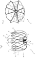
- FIG. 1 shows a cutting pattern for an implant according to alternative (a) in a two-dimensional representation, ie in a cut open and spread out form, before the thermal forming.
- the representation thus shows the originally processed pipe in a two-dimensional representation.
- a plurality of connecting webs 2 emanate from a retaining ring 4, each of which has a plurality of perforations 6 which are used to sew a covering, for example with a Teflon film, onto it.
- the connecting webs 2 each merge into two basket webs 3 which are networked with one another in an intersection plane 11 .
- two basket webs 3 converge to form a rounded tip 5, with the total number of tips 5 forming the ring-shaped distal boundary of the basket 10.
- a hook element 9 is defined by incisions, which forms the barb 9 of the tip 8 in the deformed state.
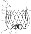
- FIG. 2 shows an implant according to alternative (a) in a lateral photographic representation with the retaining ring 4 and the cage structure 10.
- a plurality of connecting webs 2 proceed from the retaining ring and branch off to the cage structure 10 with their cage webs 3.
- the basket webs 3, which emanate from the connecting webs 2, converge in a plane 11 to branch out again and converge again.
- tips 5 are formed, which are preferably rounded.
- Two spear-shaped anchor elements 7a extend from the retaining ring 4 and form a barb 9 in the region of their tip 8 . These anchoring elements protrude beyond the basket structure 10 and serve to anchor the implant muscle tissue of the auricula sinistra in relation to the entrance.
- the basket structure 10 comes to rest on the walls, the proximal end with the retaining ring 4 is arranged in the entry area.
- the connecting webs 2, which connect the retaining ring 4 to the basket structure 10 and its web elements, have a multiply curved course, such that they first run proximally and are then bent in a semicircle towards the basket 10 distally.
- the webs 2 have perforations 6 for fixing a cover, as in 1 shown.
- Implants according to the invention are connected via the retaining ring 4 with a standard coupling mechanism to a guide catheter, which leads through a catheter to the attending physician. These techniques are well known and widely described. It is also understood that the retaining ring 4 can be closed in a suitable manner to prevent thrombi from being flushed out, for example by fitted elements, struts notched out of the retaining ring or the coupling mechanism fitted into the retaining ring, for example in the form of a plate or ball, which interact with a pincer-shaped retaining element of the guide catheter or wire.
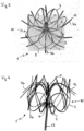
- FIG. 3 shows the implant according to 2 photographed from the proximal side.
- the retaining ring 4 is connected to the actual basket, which is formed by the basket webs 3, via eight connecting webs 2.
- Each connecting web 2 merges into two webs 3 that form the basket in the form of a network.
- the periphery of 3 is formed by the mesh structure of the basket, which terminates distally in the rim formed by the tips 5.
- the connecting webs 2 have a large number of perforations 6 which serve to fix a cover covering the implant, in the case shown by sewing.
- a cover can consist of a Teflon film, for example.
- glue the cover it is also easily possible to glue the cover, to brace it or to connect it to the implant structure by immersion or electrospinning.
- the retaining elements 7a which end in a tip 8, extend centrally from the retaining ring 4.
- the barbs 9 start from the tip 8 and point to the periphery of the basket in the case shown. The cutout from which the barb 9 was released can be seen in the holding element on the left.
- FIG. 4 shows a further variant of an implant according to alternative (a), in which the holding elements 7 with tip 8 and barbs 9 emanate from tips 5 of the crown structure of the implant. Not every tip is connected to a holding element; preferably there are two or four holding elements arranged at regular intervals.
- proximal in the sense of the description designates the side of the implant pointing towards the attending physician and catheter, the term “distal” the side of the implant pointing away from the attending physician and catheter and towards the rear wall of the auricula sinistra.
- FIG. 5 shows an implant according to alternative (b) according to the invention.
- the implant 1 has connecting webs 2 emerging from the retaining ring 4 , which branch into the webs 3 which form the actual basket 10 .
- the webs 3 are networked with one another and end in points 5, which are athromatically rounded.
- Variant (b) is characterized by anchor elements 7b, which emanate from the retaining ring 4 between the connecting webs 2 and extend laterally outwards, leaving the region of the basket 10 in the process.
- the anchor elements 7b have a curved course d. H. they are curved proximally. In this way they form a basket that runs in the opposite direction to the basket 10 . They form a ring of arms that hit the wall in the auricula sinistra and thereby fix the implant.
- FIG. 6 shows another photograph of the implant from figure 5 , in this case connected to a guide wire 13, which can be released by twisting after implantation.
- the basket structure formed by the connecting webs 2 and the webs 3 and ending in the tips 5 distal to the guide wire 13 can be clearly seen.
- the anchoring elements 7b start from the retaining ring 4, are arranged between adjacent connecting webs 2 and have a curved profile in such a way that they extend out of the basket 10 to the outside.
- the curvature of the anchor elements 7b causes them to assume an outward and backward (proximal) course in their end region. This is the basis of the locking effect that holds the implant at the implantation site in the auricula sinistra.
- the anchoring elements 7b extend from a holding tube 14, which is fitted into the holding ring 4 at its proximal end and is connected to it.
- the anchor elements 7 b begin at the distal end of the holding tube 14 , of which two adjacent ones are combined to form a loop which ends in a rounded tip 15 .
- the tip of the anchor elements 7b is bent inwards, ie bent back onto the basket.
- the anchoring element 7b is intended to be anchored or braced peripherally with the outside in the auricula sinistra.
- the inwardly curved one Tip 15 of the loop formed by two elements 7b on the one hand prevents damage to the tissue and on the other hand causes tension in the anchor elements 7b, which uses the anchoring of the implant.
- the holding tube 14 can be seen, the proximal end of which is fitted into the holding ring 4 .
- the retaining ring 4 is the starting point of the basket structure 10, which is formed from the webs 2 and 3, the webs 3 being brought together in points 5.
- the anchoring elements 7b start distally from the holding tube 14 and extend laterally beyond the basket structure with a curve towards the proximal side of the implant 1, the ends of the anchoring elements 7b being curved back onto the basket.
- Two adjacent anchor elements 7b each form a loop which ends in a point 15 pointing in the direction of the basket.
- the anchor elements 7b brace themselves peripherally against the wall of the auricula sinistra and thus ensure that the implant is retained at the site of use.
Landscapes
- Health & Medical Sciences (AREA)
- Engineering & Computer Science (AREA)
- Biomedical Technology (AREA)
- Life Sciences & Earth Sciences (AREA)
- Animal Behavior & Ethology (AREA)
- Veterinary Medicine (AREA)
- Public Health (AREA)
- Vascular Medicine (AREA)
- General Health & Medical Sciences (AREA)
- Heart & Thoracic Surgery (AREA)
- Surgery (AREA)
- Cardiology (AREA)
- Oral & Maxillofacial Surgery (AREA)
- Transplantation (AREA)
- Molecular Biology (AREA)
- Medical Informatics (AREA)
- Nuclear Medicine, Radiotherapy & Molecular Imaging (AREA)
- Reproductive Health (AREA)
- Prostheses (AREA)
- Media Introduction/Drainage Providing Device (AREA)
- Surgical Instruments (AREA)
Applications Claiming Priority (2)
| Application Number | Priority Date | Filing Date | Title |
|---|---|---|---|
| DE102013019890.9A DE102013019890A1 (de) | 2013-11-28 | 2013-11-28 | Medizinisches Implantat |
| PCT/EP2014/075942 WO2015079023A1 (de) | 2013-11-28 | 2014-11-28 | Medizinisches implantat |
Publications (2)
| Publication Number | Publication Date |
|---|---|
| EP3073936A1 EP3073936A1 (de) | 2016-10-05 |
| EP3073936B1 true EP3073936B1 (de) | 2023-07-26 |
Family
ID=52232137
Family Applications (1)
| Application Number | Title | Priority Date | Filing Date |
|---|---|---|---|
| EP14820761.6A Active EP3073936B1 (de) | 2013-11-28 | 2014-11-28 | Medizinisches implantat |
Country Status (10)
| Country | Link |
|---|---|
| US (1) | US10034786B2 (ja) |
| EP (1) | EP3073936B1 (ja) |
| JP (1) | JP6527514B2 (ja) |
| CN (1) | CN106163425B (ja) |
| BR (1) | BR112016012108B1 (ja) |
| DE (1) | DE102013019890A1 (ja) |
| ES (1) | ES2958514T3 (ja) |
| PL (1) | PL3073936T3 (ja) |
| RU (1) | RU2688695C1 (ja) |
| WO (1) | WO2015079023A1 (ja) |
Families Citing this family (12)
| Publication number | Priority date | Publication date | Assignee | Title |
|---|---|---|---|---|
| CN106923883B (zh) * | 2015-12-31 | 2019-09-03 | 先健科技(深圳)有限公司 | 左心耳封堵器 |
| CN106923886B (zh) * | 2015-12-31 | 2022-04-22 | 先健科技(深圳)有限公司 | 左心耳封堵器 |
| CN106923884B (zh) * | 2015-12-31 | 2018-12-21 | 先健科技(深圳)有限公司 | 左心耳封堵器 |
| CN110831520B (zh) * | 2017-04-27 | 2022-11-15 | 波士顿科学国际有限公司 | 具有织物保持倒钩的闭塞医疗装置 |
| EP3403596A1 (de) | 2017-05-16 | 2018-11-21 | Universitätsklinikum Jena | Implantations- und verankerungssystem für einen vorhofohrokkluder |
| US11173023B2 (en) * | 2017-10-16 | 2021-11-16 | W. L. Gore & Associates, Inc. | Medical devices and anchors therefor |
| WO2019161072A1 (en) * | 2018-02-14 | 2019-08-22 | Boston Scientific Scimed, Inc. | Occlusive medical device |
| DE102019100531B4 (de) | 2019-01-10 | 2021-08-19 | Qatna Medical GmbH | Okkludereinführsystem und Einführeinheit |
| DE102019100530B4 (de) | 2019-01-10 | 2021-05-06 | Qatna Medical GmbH | Okkluder und System zur Einführung eines Okkluders |
| EP3911277A4 (en) * | 2019-01-14 | 2023-02-22 | Valfix Medical Ltd. | PERCUTANEOUS VALVE IMPLANTS |
| CN113710171A (zh) * | 2019-02-08 | 2021-11-26 | 保形医疗公司 | 用于除去左心耳的装置和方法 |
| DE102020101456A1 (de) * | 2020-01-22 | 2021-07-22 | Andramed Gmbh | Valvulotom |
Citations (2)
| Publication number | Priority date | Publication date | Assignee | Title |
|---|---|---|---|---|
| WO2012166804A1 (en) * | 2011-06-03 | 2012-12-06 | Reverse Medical Corporation | Embolic implant and method of use |
| EP3120786A1 (en) * | 2013-06-26 | 2017-01-25 | W. L. Gore & Associates, Inc. | Space filling devices |
Family Cites Families (28)
| Publication number | Priority date | Publication date | Assignee | Title |
|---|---|---|---|---|
| US7128073B1 (en) * | 1998-11-06 | 2006-10-31 | Ev3 Endovascular, Inc. | Method and device for left atrial appendage occlusion |
| US6689150B1 (en) * | 1999-10-27 | 2004-02-10 | Atritech, Inc. | Filter apparatus for ostium of left atrial appendage |
| US6994092B2 (en) * | 1999-11-08 | 2006-02-07 | Ev3 Sunnyvale, Inc. | Device for containing embolic material in the LAA having a plurality of tissue retention structures |
| US6962598B2 (en) * | 2001-07-02 | 2005-11-08 | Rubicon Medical, Inc. | Methods, systems, and devices for providing embolic protection |
| CN1638703A (zh) * | 2002-01-25 | 2005-07-13 | 阿特里泰克公司 | 心房附件血液过滤系统 |
| US7338530B2 (en) * | 2003-11-24 | 2008-03-04 | Checkmed Systems, Inc. | Stent |
| EP2150181A1 (en) * | 2007-05-31 | 2010-02-10 | Rex Medical, L.P. | Closure device for left atrial appendage |
| US20090171386A1 (en) * | 2007-12-28 | 2009-07-02 | Aga Medical Corporation | Percutaneous catheter directed intravascular occlusion devices |
| US9504551B2 (en) * | 2008-12-17 | 2016-11-29 | Abbott Laboratories Vascular Enterprises Limited | Apparatus for filtering a body lumen |
| DE202009014247U1 (de) * | 2009-06-09 | 2010-03-04 | Bentley Surgical Gmbh | Medizinisches Implantat zum Verschließen von Gefäßöffnungen |
| US9883864B2 (en) * | 2009-06-17 | 2018-02-06 | Coherex Medical, Inc. | Medical device for modification of left atrial appendage and related systems and methods |
| US9649115B2 (en) * | 2009-06-17 | 2017-05-16 | Coherex Medical, Inc. | Medical device for modification of left atrial appendage and related systems and methods |
| US10631969B2 (en) * | 2009-06-17 | 2020-04-28 | Coherex Medical, Inc. | Medical device for modification of left atrial appendage and related systems and methods |
| US20110054515A1 (en) * | 2009-08-25 | 2011-03-03 | John Bridgeman | Device and method for occluding the left atrial appendage |
| US10433956B2 (en) * | 2010-02-24 | 2019-10-08 | Medtronic Ventor Technologies Ltd. | Mitral prosthesis and methods for implantation |
| US8579964B2 (en) * | 2010-05-05 | 2013-11-12 | Neovasc Inc. | Transcatheter mitral valve prosthesis |
| CN103153232B (zh) * | 2010-10-21 | 2016-09-21 | 美敦力公司 | 具有低心室型面的二尖瓣假体 |
| CN202143640U (zh) * | 2011-06-01 | 2012-02-15 | 先健科技(深圳)有限公司 | 左心耳封堵器 |
| US9554806B2 (en) * | 2011-09-16 | 2017-01-31 | W. L. Gore & Associates, Inc. | Occlusive devices |
| CN202335893U (zh) * | 2011-10-31 | 2012-07-18 | 上海形状记忆合金材料有限公司 | 左心耳封堵装置 |
| EP3682813B1 (en) * | 2011-11-01 | 2023-12-27 | Coherex Medical, Inc. | Medical device for modification of left atrial appendage |
| JP2014533970A (ja) * | 2011-11-09 | 2014-12-18 | ボストン サイエンティフィック サイムド,インコーポレイテッドBoston Scientific Scimed,Inc. | 閉塞デバイス |
| EP2838444A4 (en) * | 2012-04-20 | 2016-02-24 | Inceptus Medical LLC | EXPANDABLE OCCLUSION DEVICES AND METHODS OF USE |
| US20140135817A1 (en) * | 2012-11-14 | 2014-05-15 | Boston Scientific Scimed, Inc. | Left atrial appendage closure implant |
| RU128101U1 (ru) * | 2012-12-17 | 2013-05-20 | Общество с ограниченной ответственностью "Ангиолайн интервеншионал девайс" | Окклюдер |
| US11911258B2 (en) * | 2013-06-26 | 2024-02-27 | W. L. Gore & Associates, Inc. | Space filling devices |
| WO2015189307A1 (en) * | 2014-06-11 | 2015-12-17 | Occlutech Holding Ag | Left atrial appendage occluder |
| DE102015104785A1 (de) * | 2015-03-27 | 2016-09-29 | Pfm Medical Ag | Vorrichtung zum Verschließen eines Herzohrs |
-
2013
- 2013-11-28 DE DE102013019890.9A patent/DE102013019890A1/de active Pending
-
2014
- 2014-11-28 RU RU2016125511A patent/RU2688695C1/ru active
- 2014-11-28 BR BR112016012108-2A patent/BR112016012108B1/pt active IP Right Grant
- 2014-11-28 PL PL14820761.6T patent/PL3073936T3/pl unknown
- 2014-11-28 JP JP2016534927A patent/JP6527514B2/ja active Active
- 2014-11-28 EP EP14820761.6A patent/EP3073936B1/de active Active
- 2014-11-28 WO PCT/EP2014/075942 patent/WO2015079023A1/de active Application Filing
- 2014-11-28 CN CN201480073257.8A patent/CN106163425B/zh active Active
- 2014-11-28 US US15/039,331 patent/US10034786B2/en active Active
- 2014-11-28 ES ES14820761T patent/ES2958514T3/es active Active
Patent Citations (2)
| Publication number | Priority date | Publication date | Assignee | Title |
|---|---|---|---|---|
| WO2012166804A1 (en) * | 2011-06-03 | 2012-12-06 | Reverse Medical Corporation | Embolic implant and method of use |
| EP3120786A1 (en) * | 2013-06-26 | 2017-01-25 | W. L. Gore & Associates, Inc. | Space filling devices |
Also Published As
| Publication number | Publication date |
|---|---|
| ES2958514T3 (es) | 2024-02-09 |
| BR112016012108B1 (pt) | 2022-03-03 |
| US20170156898A1 (en) | 2017-06-08 |
| JP6527514B2 (ja) | 2019-06-05 |
| CN106163425B (zh) | 2022-01-07 |
| PL3073936T3 (pl) | 2024-02-05 |
| EP3073936A1 (de) | 2016-10-05 |
| BR112016012108A2 (ja) | 2017-08-08 |
| CN106163425A (zh) | 2016-11-23 |
| US10034786B2 (en) | 2018-07-31 |
| JP2017503538A (ja) | 2017-02-02 |
| RU2016125511A (ru) | 2018-01-10 |
| RU2688695C1 (ru) | 2019-05-22 |
| DE102013019890A1 (de) | 2015-05-28 |
| WO2015079023A1 (de) | 2015-06-04 |
Similar Documents
| Publication | Publication Date | Title |
|---|---|---|
| EP3073936B1 (de) | Medizinisches implantat | |
| EP2259728B1 (de) | Vorrichtung zum verschluss von defekten im gefässsystem | |
| EP1948030B1 (de) | Occlusionsinstrument zum verschliessen eines herzohres | |
| EP1722695B1 (de) | Vorrichtung zur rekanalisierung eines hohlraums, organwegs oder gef sses | |
| EP2571431B1 (de) | Medizinische vorrichtung zum entfernen von konkrementen | |
| DE69533985T2 (de) | Stent | |
| EP1648342B1 (de) | Geflochtener stent zur implantation in ein blutgefäss | |
| EP2706929B9 (de) | Thrombektomievorrichtung | |
| DE60031413T2 (de) | Medizinische vorrichtungen aus nitinol mit erzielter variabler steifheit durch wärmebehandlung | |
| EP1962702B1 (de) | Vorrichtung zur Entfernung von Thromben aus Blutgefässen | |
| DE69633824T2 (de) | Vorrichtung zur implantierung in einem blutgefäss beziehungsweise in einem hohlen körperlumen | |
| EP1667608B1 (de) | Stent mit endständigen verankerungselementen | |
| DE29825257U1 (de) | Perkutane kathetergeführte Verschlussvorrichtungen | |
| WO2014026870A2 (de) | Implantierbare einrichtung zur verwendung im menschlichen und/oder tierischen körper zum ersatz einer organklappe | |
| EP2698130B1 (de) | Verfahren zum Herstellen eines Körperimplantats | |
| DE202007005491U1 (de) | Medizinische Vorrichtung zur Behandlung einer Aortenklappeninsuffizienz | |
| DE102010035543A1 (de) | Medizinische Vorrichtung und System mit einer derartigen Vorrichtung | |
| EP3764928B1 (de) | Thrombektomievorrichtung | |
| DE102012107175B4 (de) | Medizinische Verschlussvorrichtung und System mit einer derartigen Verschlussvorrichtung | |
| EP3389511B1 (de) | Implantat | |
| EP3320862B1 (de) | Einrichtung zum positionieren und freisetzen eines verschlussimplantats zum verschliessen des linken herzohrs | |
| DE202020107453U1 (de) | Stent, insbesondere zur Behandlung von Erkrankungen der Halsschlagader | |
| DE20314392U1 (de) | Stent mit endständigen Verankerungselementen | |
| EP3773357A1 (de) | Verzweigter stent und stentsystem |
Legal Events
| Date | Code | Title | Description |
|---|---|---|---|
| PUAI | Public reference made under article 153(3) epc to a published international application that has entered the european phase |
Free format text: ORIGINAL CODE: 0009012 |
|
| 17P | Request for examination filed |
Effective date: 20160628 |
|
| AK | Designated contracting states |
Kind code of ref document: A1 Designated state(s): AL AT BE BG CH CY CZ DE DK EE ES FI FR GB GR HR HU IE IS IT LI LT LU LV MC MK MT NL NO PL PT RO RS SE SI SK SM TR |
|
| AX | Request for extension of the european patent |
Extension state: BA ME |
|
| RIN1 | Information on inventor provided before grant (corrected) |
Inventor name: OBRADOVIC, MILISAV |
|
| DAX | Request for extension of the european patent (deleted) | ||
| STAA | Information on the status of an ep patent application or granted ep patent |
Free format text: STATUS: EXAMINATION IS IN PROGRESS |
|
| 17Q | First examination report despatched |
Effective date: 20171108 |
|
| RAP1 | Party data changed (applicant data changed or rights of an application transferred) |
Owner name: BENTLEY INNOMED GMBH |
|
| STAA | Information on the status of an ep patent application or granted ep patent |
Free format text: STATUS: EXAMINATION IS IN PROGRESS |
|
| GRAP | Despatch of communication of intention to grant a patent |
Free format text: ORIGINAL CODE: EPIDOSNIGR1 |
|
| STAA | Information on the status of an ep patent application or granted ep patent |
Free format text: STATUS: GRANT OF PATENT IS INTENDED |
|
| RIC1 | Information provided on ipc code assigned before grant |
Ipc: A61B 17/00 20060101ALN20230201BHEP Ipc: A61B 17/12 20060101AFI20230201BHEP |
|
| INTG | Intention to grant announced |
Effective date: 20230215 |
|
| GRAS | Grant fee paid |
Free format text: ORIGINAL CODE: EPIDOSNIGR3 |
|
| GRAA | (expected) grant |
Free format text: ORIGINAL CODE: 0009210 |
|
| STAA | Information on the status of an ep patent application or granted ep patent |
Free format text: STATUS: THE PATENT HAS BEEN GRANTED |
|
| AK | Designated contracting states |
Kind code of ref document: B1 Designated state(s): AL AT BE BG CH CY CZ DE DK EE ES FI FR GB GR HR HU IE IS IT LI LT LU LV MC MK MT NL NO PL PT RO RS SE SI SK SM TR |
|
| REG | Reference to a national code |
Ref country code: CH Ref legal event code: EP |
|
| REG | Reference to a national code |
Ref country code: IE Ref legal event code: FG4D Free format text: LANGUAGE OF EP DOCUMENT: GERMAN |
|
| REG | Reference to a national code |
Ref country code: DE Ref legal event code: R096 Ref document number: 502014016641 Country of ref document: DE |
|
| REG | Reference to a national code |
Ref country code: NL Ref legal event code: FP |
|
| REG | Reference to a national code |
Ref country code: LT Ref legal event code: MG9D |
|
| PGFP | Annual fee paid to national office [announced via postgrant information from national office to epo] |
Ref country code: NL Payment date: 20231122 Year of fee payment: 10 |
|
| PG25 | Lapsed in a contracting state [announced via postgrant information from national office to epo] |
Ref country code: GR Free format text: LAPSE BECAUSE OF FAILURE TO SUBMIT A TRANSLATION OF THE DESCRIPTION OR TO PAY THE FEE WITHIN THE PRESCRIBED TIME-LIMIT Effective date: 20231027 |
|
| PGFP | Annual fee paid to national office [announced via postgrant information from national office to epo] |
Ref country code: ES Payment date: 20231215 Year of fee payment: 10 |
|
| PG25 | Lapsed in a contracting state [announced via postgrant information from national office to epo] |
Ref country code: IS Free format text: LAPSE BECAUSE OF FAILURE TO SUBMIT A TRANSLATION OF THE DESCRIPTION OR TO PAY THE FEE WITHIN THE PRESCRIBED TIME-LIMIT Effective date: 20231126 |
|
| PG25 | Lapsed in a contracting state [announced via postgrant information from national office to epo] |
Ref country code: SE Free format text: LAPSE BECAUSE OF FAILURE TO SUBMIT A TRANSLATION OF THE DESCRIPTION OR TO PAY THE FEE WITHIN THE PRESCRIBED TIME-LIMIT Effective date: 20230726 Ref country code: RS Free format text: LAPSE BECAUSE OF FAILURE TO SUBMIT A TRANSLATION OF THE DESCRIPTION OR TO PAY THE FEE WITHIN THE PRESCRIBED TIME-LIMIT Effective date: 20230726 Ref country code: PT Free format text: LAPSE BECAUSE OF FAILURE TO SUBMIT A TRANSLATION OF THE DESCRIPTION OR TO PAY THE FEE WITHIN THE PRESCRIBED TIME-LIMIT Effective date: 20231127 Ref country code: NO Free format text: LAPSE BECAUSE OF FAILURE TO SUBMIT A TRANSLATION OF THE DESCRIPTION OR TO PAY THE FEE WITHIN THE PRESCRIBED TIME-LIMIT Effective date: 20231026 Ref country code: LV Free format text: LAPSE BECAUSE OF FAILURE TO SUBMIT A TRANSLATION OF THE DESCRIPTION OR TO PAY THE FEE WITHIN THE PRESCRIBED TIME-LIMIT Effective date: 20230726 Ref country code: LT Free format text: LAPSE BECAUSE OF FAILURE TO SUBMIT A TRANSLATION OF THE DESCRIPTION OR TO PAY THE FEE WITHIN THE PRESCRIBED TIME-LIMIT Effective date: 20230726 Ref country code: IS Free format text: LAPSE BECAUSE OF FAILURE TO SUBMIT A TRANSLATION OF THE DESCRIPTION OR TO PAY THE FEE WITHIN THE PRESCRIBED TIME-LIMIT Effective date: 20231126 Ref country code: HR Free format text: LAPSE BECAUSE OF FAILURE TO SUBMIT A TRANSLATION OF THE DESCRIPTION OR TO PAY THE FEE WITHIN THE PRESCRIBED TIME-LIMIT Effective date: 20230726 Ref country code: GR Free format text: LAPSE BECAUSE OF FAILURE TO SUBMIT A TRANSLATION OF THE DESCRIPTION OR TO PAY THE FEE WITHIN THE PRESCRIBED TIME-LIMIT Effective date: 20231027 Ref country code: FI Free format text: LAPSE BECAUSE OF FAILURE TO SUBMIT A TRANSLATION OF THE DESCRIPTION OR TO PAY THE FEE WITHIN THE PRESCRIBED TIME-LIMIT Effective date: 20230726 |
|
| PGFP | Annual fee paid to national office [announced via postgrant information from national office to epo] |
Ref country code: IT Payment date: 20231130 Year of fee payment: 10 Ref country code: IE Payment date: 20231117 Year of fee payment: 10 Ref country code: DE Payment date: 20231130 Year of fee payment: 10 Ref country code: AT Payment date: 20231117 Year of fee payment: 10 |
|
| REG | Reference to a national code |
Ref country code: ES Ref legal event code: FG2A Ref document number: 2958514 Country of ref document: ES Kind code of ref document: T3 Effective date: 20240209 |
|
| PG25 | Lapsed in a contracting state [announced via postgrant information from national office to epo] |
Ref country code: SM Free format text: LAPSE BECAUSE OF FAILURE TO SUBMIT A TRANSLATION OF THE DESCRIPTION OR TO PAY THE FEE WITHIN THE PRESCRIBED TIME-LIMIT Effective date: 20230726 Ref country code: RO Free format text: LAPSE BECAUSE OF FAILURE TO SUBMIT A TRANSLATION OF THE DESCRIPTION OR TO PAY THE FEE WITHIN THE PRESCRIBED TIME-LIMIT Effective date: 20230726 Ref country code: EE Free format text: LAPSE BECAUSE OF FAILURE TO SUBMIT A TRANSLATION OF THE DESCRIPTION OR TO PAY THE FEE WITHIN THE PRESCRIBED TIME-LIMIT Effective date: 20230726 Ref country code: DK Free format text: LAPSE BECAUSE OF FAILURE TO SUBMIT A TRANSLATION OF THE DESCRIPTION OR TO PAY THE FEE WITHIN THE PRESCRIBED TIME-LIMIT Effective date: 20230726 Ref country code: CZ Free format text: LAPSE BECAUSE OF FAILURE TO SUBMIT A TRANSLATION OF THE DESCRIPTION OR TO PAY THE FEE WITHIN THE PRESCRIBED TIME-LIMIT Effective date: 20230726 Ref country code: SK Free format text: LAPSE BECAUSE OF FAILURE TO SUBMIT A TRANSLATION OF THE DESCRIPTION OR TO PAY THE FEE WITHIN THE PRESCRIBED TIME-LIMIT Effective date: 20230726 |