EP3073936B1 - Medical implant - Google Patents
Medical implant Download PDFInfo
- Publication number
- EP3073936B1 EP3073936B1 EP14820761.6A EP14820761A EP3073936B1 EP 3073936 B1 EP3073936 B1 EP 3073936B1 EP 14820761 A EP14820761 A EP 14820761A EP 3073936 B1 EP3073936 B1 EP 3073936B1
- Authority
- EP
- European Patent Office
- Prior art keywords
- cage structure
- retaining ring
- implant
- implant according
- anchor elements
- Prior art date
- Legal status (The legal status is an assumption and is not a legal conclusion. Google has not performed a legal analysis and makes no representation as to the accuracy of the status listed.)
- Active
Links
- 239000007943 implant Substances 0.000 title claims description 92
- 241001088162 Primula auricula Species 0.000 claims description 28
- 235000006894 Primula auricula Nutrition 0.000 claims description 28
- 210000003205 muscle Anatomy 0.000 claims description 11
- 239000000463 material Substances 0.000 claims description 6
- 230000008878 coupling Effects 0.000 claims description 5
- 238000010168 coupling process Methods 0.000 claims description 5
- 238000005859 coupling reaction Methods 0.000 claims description 5
- 239000004809 Teflon Substances 0.000 claims description 4
- 229920006362 Teflon® Polymers 0.000 claims description 4
- 229910052751 metal Inorganic materials 0.000 claims description 3
- 239000002184 metal Substances 0.000 claims description 3
- 238000009958 sewing Methods 0.000 claims description 2
- 238000004873 anchoring Methods 0.000 description 19
- 230000007246 mechanism Effects 0.000 description 4
- 238000002513 implantation Methods 0.000 description 3
- 238000000034 method Methods 0.000 description 3
- 208000007536 Thrombosis Diseases 0.000 description 2
- 238000005520 cutting process Methods 0.000 description 2
- 238000007654 immersion Methods 0.000 description 2
- 238000003698 laser cutting Methods 0.000 description 2
- 210000005248 left atrial appendage Anatomy 0.000 description 2
- 238000004519 manufacturing process Methods 0.000 description 2
- 229910001000 nickel titanium Inorganic materials 0.000 description 2
- 239000004033 plastic Substances 0.000 description 2
- 229920003023 plastic Polymers 0.000 description 2
- 238000011321 prophylaxis Methods 0.000 description 2
- 229910001285 shape-memory alloy Inorganic materials 0.000 description 2
- 238000005496 tempering Methods 0.000 description 2
- 206010003658 Atrial Fibrillation Diseases 0.000 description 1
- 241001295925 Gegenes Species 0.000 description 1
- 241000124008 Mammalia Species 0.000 description 1
- 244000089486 Phragmites australis subsp australis Species 0.000 description 1
- HZEWFHLRYVTOIW-UHFFFAOYSA-N [Ti].[Ni] Chemical compound [Ti].[Ni] HZEWFHLRYVTOIW-UHFFFAOYSA-N 0.000 description 1
- 238000004026 adhesive bonding Methods 0.000 description 1
- 229910045601 alloy Inorganic materials 0.000 description 1
- 239000000956 alloy Substances 0.000 description 1
- 238000000137 annealing Methods 0.000 description 1
- 210000001008 atrial appendage Anatomy 0.000 description 1
- 230000017531 blood circulation Effects 0.000 description 1
- 239000006185 dispersion Substances 0.000 description 1
- 238000009826 distribution Methods 0.000 description 1
- 230000000694 effects Effects 0.000 description 1
- 238000001523 electrospinning Methods 0.000 description 1
- 238000012282 endovascular technique Methods 0.000 description 1
- 239000011888 foil Substances 0.000 description 1
- 239000003292 glue Substances 0.000 description 1
- 210000002837 heart atrium Anatomy 0.000 description 1
- 229910001092 metal group alloy Inorganic materials 0.000 description 1
- 150000002739 metals Chemical class 0.000 description 1
- HLXZNVUGXRDIFK-UHFFFAOYSA-N nickel titanium Chemical compound [Ti].[Ti].[Ti].[Ti].[Ti].[Ti].[Ti].[Ti].[Ti].[Ti].[Ti].[Ni].[Ni].[Ni].[Ni].[Ni].[Ni].[Ni].[Ni].[Ni].[Ni].[Ni].[Ni].[Ni].[Ni] HLXZNVUGXRDIFK-UHFFFAOYSA-N 0.000 description 1
- 230000000149 penetrating effect Effects 0.000 description 1
- 229920000728 polyester Polymers 0.000 description 1
- 229920002635 polyurethane Polymers 0.000 description 1
- 239000004814 polyurethane Substances 0.000 description 1
- 230000002265 prevention Effects 0.000 description 1
- 210000001147 pulmonary artery Anatomy 0.000 description 1
- 230000000717 retained effect Effects 0.000 description 1
- 210000001519 tissue Anatomy 0.000 description 1
Images


Classifications
-
- A—HUMAN NECESSITIES
- A61—MEDICAL OR VETERINARY SCIENCE; HYGIENE
- A61F—FILTERS IMPLANTABLE INTO BLOOD VESSELS; PROSTHESES; DEVICES PROVIDING PATENCY TO, OR PREVENTING COLLAPSING OF, TUBULAR STRUCTURES OF THE BODY, e.g. STENTS; ORTHOPAEDIC, NURSING OR CONTRACEPTIVE DEVICES; FOMENTATION; TREATMENT OR PROTECTION OF EYES OR EARS; BANDAGES, DRESSINGS OR ABSORBENT PADS; FIRST-AID KITS
- A61F2/00—Filters implantable into blood vessels; Prostheses, i.e. artificial substitutes or replacements for parts of the body; Appliances for connecting them with the body; Devices providing patency to, or preventing collapsing of, tubular structures of the body, e.g. stents
- A61F2/82—Devices providing patency to, or preventing collapsing of, tubular structures of the body, e.g. stents
- A61F2/86—Stents in a form characterised by the wire-like elements; Stents in the form characterised by a net-like or mesh-like structure
- A61F2/90—Stents in a form characterised by the wire-like elements; Stents in the form characterised by a net-like or mesh-like structure characterised by a net-like or mesh-like structure
-
- A—HUMAN NECESSITIES
- A61—MEDICAL OR VETERINARY SCIENCE; HYGIENE
- A61B—DIAGNOSIS; SURGERY; IDENTIFICATION
- A61B17/00—Surgical instruments, devices or methods, e.g. tourniquets
- A61B17/12—Surgical instruments, devices or methods, e.g. tourniquets for ligaturing or otherwise compressing tubular parts of the body, e.g. blood vessels, umbilical cord
- A61B17/12022—Occluding by internal devices, e.g. balloons or releasable wires
- A61B17/12099—Occluding by internal devices, e.g. balloons or releasable wires characterised by the location of the occluder
- A61B17/12122—Occluding by internal devices, e.g. balloons or releasable wires characterised by the location of the occluder within the heart
-
- A—HUMAN NECESSITIES
- A61—MEDICAL OR VETERINARY SCIENCE; HYGIENE
- A61B—DIAGNOSIS; SURGERY; IDENTIFICATION
- A61B17/00—Surgical instruments, devices or methods, e.g. tourniquets
- A61B17/12—Surgical instruments, devices or methods, e.g. tourniquets for ligaturing or otherwise compressing tubular parts of the body, e.g. blood vessels, umbilical cord
- A61B17/12022—Occluding by internal devices, e.g. balloons or releasable wires
- A61B17/12131—Occluding by internal devices, e.g. balloons or releasable wires characterised by the type of occluding device
- A61B17/12168—Occluding by internal devices, e.g. balloons or releasable wires characterised by the type of occluding device having a mesh structure
- A61B17/12172—Occluding by internal devices, e.g. balloons or releasable wires characterised by the type of occluding device having a mesh structure having a pre-set deployed three-dimensional shape
-
- A—HUMAN NECESSITIES
- A61—MEDICAL OR VETERINARY SCIENCE; HYGIENE
- A61F—FILTERS IMPLANTABLE INTO BLOOD VESSELS; PROSTHESES; DEVICES PROVIDING PATENCY TO, OR PREVENTING COLLAPSING OF, TUBULAR STRUCTURES OF THE BODY, e.g. STENTS; ORTHOPAEDIC, NURSING OR CONTRACEPTIVE DEVICES; FOMENTATION; TREATMENT OR PROTECTION OF EYES OR EARS; BANDAGES, DRESSINGS OR ABSORBENT PADS; FIRST-AID KITS
- A61F2/00—Filters implantable into blood vessels; Prostheses, i.e. artificial substitutes or replacements for parts of the body; Appliances for connecting them with the body; Devices providing patency to, or preventing collapsing of, tubular structures of the body, e.g. stents
- A61F2/82—Devices providing patency to, or preventing collapsing of, tubular structures of the body, e.g. stents
- A61F2/844—Devices providing patency to, or preventing collapsing of, tubular structures of the body, e.g. stents folded prior to deployment
-
- A—HUMAN NECESSITIES
- A61—MEDICAL OR VETERINARY SCIENCE; HYGIENE
- A61F—FILTERS IMPLANTABLE INTO BLOOD VESSELS; PROSTHESES; DEVICES PROVIDING PATENCY TO, OR PREVENTING COLLAPSING OF, TUBULAR STRUCTURES OF THE BODY, e.g. STENTS; ORTHOPAEDIC, NURSING OR CONTRACEPTIVE DEVICES; FOMENTATION; TREATMENT OR PROTECTION OF EYES OR EARS; BANDAGES, DRESSINGS OR ABSORBENT PADS; FIRST-AID KITS
- A61F2/00—Filters implantable into blood vessels; Prostheses, i.e. artificial substitutes or replacements for parts of the body; Appliances for connecting them with the body; Devices providing patency to, or preventing collapsing of, tubular structures of the body, e.g. stents
- A61F2/82—Devices providing patency to, or preventing collapsing of, tubular structures of the body, e.g. stents
- A61F2/848—Devices providing patency to, or preventing collapsing of, tubular structures of the body, e.g. stents having means for fixation to the vessel wall, e.g. barbs
-
- A—HUMAN NECESSITIES
- A61—MEDICAL OR VETERINARY SCIENCE; HYGIENE
- A61B—DIAGNOSIS; SURGERY; IDENTIFICATION
- A61B17/00—Surgical instruments, devices or methods, e.g. tourniquets
- A61B17/0057—Implements for plugging an opening in the wall of a hollow or tubular organ, e.g. for sealing a vessel puncture or closing a cardiac septal defect
- A61B2017/00575—Implements for plugging an opening in the wall of a hollow or tubular organ, e.g. for sealing a vessel puncture or closing a cardiac septal defect for closure at remote site, e.g. closing atrial septum defects
- A61B2017/00579—Barbed implements
-
- A—HUMAN NECESSITIES
- A61—MEDICAL OR VETERINARY SCIENCE; HYGIENE
- A61B—DIAGNOSIS; SURGERY; IDENTIFICATION
- A61B17/00—Surgical instruments, devices or methods, e.g. tourniquets
- A61B17/0057—Implements for plugging an opening in the wall of a hollow or tubular organ, e.g. for sealing a vessel puncture or closing a cardiac septal defect
- A61B2017/00575—Implements for plugging an opening in the wall of a hollow or tubular organ, e.g. for sealing a vessel puncture or closing a cardiac septal defect for closure at remote site, e.g. closing atrial septum defects
- A61B2017/00597—Implements comprising a membrane
-
- A—HUMAN NECESSITIES
- A61—MEDICAL OR VETERINARY SCIENCE; HYGIENE
- A61B—DIAGNOSIS; SURGERY; IDENTIFICATION
- A61B17/00—Surgical instruments, devices or methods, e.g. tourniquets
- A61B17/0057—Implements for plugging an opening in the wall of a hollow or tubular organ, e.g. for sealing a vessel puncture or closing a cardiac septal defect
- A61B2017/00575—Implements for plugging an opening in the wall of a hollow or tubular organ, e.g. for sealing a vessel puncture or closing a cardiac septal defect for closure at remote site, e.g. closing atrial septum defects
- A61B2017/00632—Occluding a cavity, i.e. closing a blind opening
-
- A—HUMAN NECESSITIES
- A61—MEDICAL OR VETERINARY SCIENCE; HYGIENE
- A61F—FILTERS IMPLANTABLE INTO BLOOD VESSELS; PROSTHESES; DEVICES PROVIDING PATENCY TO, OR PREVENTING COLLAPSING OF, TUBULAR STRUCTURES OF THE BODY, e.g. STENTS; ORTHOPAEDIC, NURSING OR CONTRACEPTIVE DEVICES; FOMENTATION; TREATMENT OR PROTECTION OF EYES OR EARS; BANDAGES, DRESSINGS OR ABSORBENT PADS; FIRST-AID KITS
- A61F2/00—Filters implantable into blood vessels; Prostheses, i.e. artificial substitutes or replacements for parts of the body; Appliances for connecting them with the body; Devices providing patency to, or preventing collapsing of, tubular structures of the body, e.g. stents
- A61F2/82—Devices providing patency to, or preventing collapsing of, tubular structures of the body, e.g. stents
- A61F2/848—Devices providing patency to, or preventing collapsing of, tubular structures of the body, e.g. stents having means for fixation to the vessel wall, e.g. barbs
- A61F2002/8483—Barbs
-
- A—HUMAN NECESSITIES
- A61—MEDICAL OR VETERINARY SCIENCE; HYGIENE
- A61F—FILTERS IMPLANTABLE INTO BLOOD VESSELS; PROSTHESES; DEVICES PROVIDING PATENCY TO, OR PREVENTING COLLAPSING OF, TUBULAR STRUCTURES OF THE BODY, e.g. STENTS; ORTHOPAEDIC, NURSING OR CONTRACEPTIVE DEVICES; FOMENTATION; TREATMENT OR PROTECTION OF EYES OR EARS; BANDAGES, DRESSINGS OR ABSORBENT PADS; FIRST-AID KITS
- A61F2/00—Filters implantable into blood vessels; Prostheses, i.e. artificial substitutes or replacements for parts of the body; Appliances for connecting them with the body; Devices providing patency to, or preventing collapsing of, tubular structures of the body, e.g. stents
- A61F2/82—Devices providing patency to, or preventing collapsing of, tubular structures of the body, e.g. stents
- A61F2/848—Devices providing patency to, or preventing collapsing of, tubular structures of the body, e.g. stents having means for fixation to the vessel wall, e.g. barbs
- A61F2002/8486—Devices providing patency to, or preventing collapsing of, tubular structures of the body, e.g. stents having means for fixation to the vessel wall, e.g. barbs provided on at least one of the ends
Definitions
- the invention relates to a medical implant for closing the auricula sinistra of a patient in an endovascular way, which has a basket structure made up of a large number of webs, which is connected proximally via connecting webs to a retaining ring and is limited distally by a ring of converging webs, the implant being made of a self-expanding material, having the shape of a slotted tube in a contracted state and, after expansion, assuming a basket structure with a diameter that is larger than that of the retaining ring.
- the auriculae atrii or atrial appendages are protuberances of the atria of the heart in mammals.
- the left atrial appendage medically known as the left auricula, lies adjacent to the trunk of the pulmonary artery and is a common site for blood clots, particularly in patients with atrial fibrillation, which can lead to a stroke.
- the prevention of thrombi in the auricula sinistra therefore represents an effective stroke prophylaxis in at-risk patients.
- LAA left atrial appendage
- the correct and reliable anchoring of the implants is often a problem.
- the size and shape of the auricula sinistra can vary from patient to patient and can be narrower and wider, especially with regard to the access opening. Implants that are tensioned by the expansion with the walls of the auricula can therefore slip if they are not optimally seated and thus not optimally fulfill their purpose. In such cases, thrombi can still be washed away, especially when the patient is under physical strain.
- U.S. 2003/220667 A1 discloses an implant for closing the left auricle having a self-expanding frame.
- U.S. 2004/122467 A1 also discloses an implant for closing the auricula sinistra, which has a self-expanding frame, the frame having anchoring elements at the distal end.
- U.S. 2011/054515 A1 and CN 202 143 640 U each disclose an implant for closing the auricula sinistra, which has a basket-shaped frame, the frame having anchoring elements.
- the implant according to the invention has a retaining ring which is connected via a plurality of webs to a cage structure arranged distally to the retaining ring.
- the basket structure is greatly expanded compared to the retaining ring. It is formed by a large number of webs, which expediently form a mesh or network structure.
- the cage structure ends proximally in the retaining ring, it is open distally and is delimited by a ring of webs arranged in a zigzag shape and converging.
- the basket structure consists of a network of webs that branch out and converge again.
- the implant For anchoring in the muscle tissue of the auricula sinistra according to alternative (a), the implant has one or more anchor elements that protrude beyond the basket structure. Each anchor element terminates in a barbed tip designed to hook into muscle tissue.
- the implant according to the invention has several anchoring elements which protrude laterally from the cage structure, curve proximally and are intended to be laterally supported against the muscle tissue of the auricula sinistra.
- the anchoring elements form a second proximally open basket, with the ends of the anchoring elements defining the edge of the basket and being supported on the muscle tissue laterally from the entrance of the auricula sinistra.
- the ends of the anchor elements can optionally also have barbs, but it is usually sufficient for the tips to be rounded. In the latter case, too, there is secure support through the expansion in the auricula sinistra.
- the anchoring elements emanate directly from the retaining ring and protrude beyond the basket structure so that they can be brought into contact with the muscle tissue of the left auricle.
- the anchor element or elements are located on the distal tips of the rim of the cage structure.
- the barbs can point outwards or inwards; preferably the barbs are located on the outside. If there are several anchor elements, these are preferably distributed evenly over the rim, with not every point of the rim having to have an anchor element.
- anchor element or each anchor element starts from the retaining ring of the implant and runs through the cage structure and protrudes distally beyond it.
- the anchor element or elements are thus located approximately in the middle of the basket structure.
- a regular distribution of the anchor elements is preferred if several anchor elements are provided.
- the medical implant according to the invention is transported to its place of use via a conventional catheter and released from the catheter there.
- the catheter In the catheter, it is in a reduced-volume, contracted and stretched form and essentially has the shape of a tube with multiple slits.
- the shape corresponds to the tube from which the implant was created by laser cutting.
- the implant Upon release from the catheter, the implant assumes the expanded shape imparted by an annealing process, i. H. the basket shape with the anchor elements protruding beyond it.
- the implant guided in the catheter is connected to a guide element, preferably a guide catheter or guide wire, via the retaining ring by means of a coupling mechanism.
- a guide element preferably a guide catheter or guide wire
- the implant is then pushed into the auricula sinistera using a guide element and expanded.
- the anchor elements located in the center of the basket structure are outside the basket with their tips and barbs.
- the necessary pressure can be exerted by means of a guide catheter and/or guide wire in order to anchor the tips with the barbs in the muscle tissue on the posterior wall of the auricle.
- the tips with the barbs grow in and out without any problems reliably hold the implant in the selected position.
- the guiding element is detached from the implant in the usual manner and withdrawn together with the catheter.
- Such coupling mechanisms are known and have been described many times.
- the basket structure of the medical implant according to the invention is usually connected to the retaining ring via 6 to 12 connecting webs.
- the implant according to the invention can fulfill its purpose as a thrombus filter even without a cover or covering.
- the medical implant is expediently provided with a cover in the proximal area, for example a polyurethane, polyester or Teflon film.
- a cover in the proximal area, for example a polyurethane, polyester or Teflon film.
- the connecting webs extending from the retaining ring with perforations that can be used to sew the cover.
- the cover can also be fixed by gluing or by (repeated) immersion of the implant in a plastic solution or dispersion.
- the implants preferably have one or more anchor elements inside the basket, which, starting from the retaining ring (a), project spear-like out of the opening of the basket structure and have a tip with at least one barb.
- the tip and barb are located outside of the basket structure and are capable of penetrating and hooking into the muscle tissue of the left auricle when appropriate pressure is applied during placement using the guide wire.
- the anchor elements protrude laterally beyond the cage structure and are curved proximally, so that they support the implant against the side wall in the entry area of the left auricula.
- a combination of the two variants (a) and (b) is also possible.
- the implant is reliably fixed in such a way that the proximal part of the basket with the retaining ring in the entrance area is located.
- the basket with or without a cover shields the auricula sinistra and prevents thrombi from being flushed out.
- the anchor elements form the distal end of the basket.
- one anchor element according to alternative (a) is sufficient, but the implant preferably has two or more anchor elements which are distributed evenly over the circumference of the retaining ring.
- An arrangement with two anchor elements that face each other on the retaining ring is particularly preferred.
- the anchor elements in the center of the basket run essentially parallel to one another at about the middle of the basket structure.
- a large number of anchor elements is expedient, with the number being based on the number of connecting webs between the retaining ring and basket.
- the anchoring elements are distributed evenly over the circumference of the retaining ring. They are expediently arranged between two connecting webs in each case.
- the basket structure preferably has a network of branching and converging webs that form diamond-shaped structures. Converging webs in the distal area result in a ring of converging webs with a zigzag course, the tips of which are preferably rounded. A meandering, rounded course is also possible. When arranging the anchor elements on the rim, a zigzag course with anchor elements placed on the tips of the rim is preferred.
- the central retaining ring is preferably arranged in a central depression in the basket structure. This means that the connecting webs between the retaining ring and the cage structure run in an S-shape, ie starting from the distal side of the retaining ring they first turn proximally before they orientate themselves distally again and merge into the cage structure.
- the anchor elements are arranged distally to the cage structure and extend laterally beyond the cage structure.
- the anchoring elements emanate from a holding tube, which in turn is connected to the holding ring of the basket structure.
- the holding tube expediently has a somewhat smaller diameter than the holding ring and is fitted into it and connected to the holding ring, for example welded.
- the anchor elements are preferably connected to one another in pairs at the tips, so that they form a type of loop.
- the tips can be bent back onto the basket, so that the anchor elements brace themselves with their outer surfaces on the periphery against the auricula sinistra.
- the implants according to the invention consist of a flexible, self-expanding material.
- This material can be a metal or a plastic, but is suitably a metal alloy with shape memory properties.
- shape-memory metals are able, under external pressure, to assume the original production-related shape and, when this pressure is removed, to assume a later imprinted shape, which is fixed by tempering, again. This allows such implants to be transported in a small diameter catheter and then expanded upon release from the catheter.
- the implants according to the invention are also produced from a tube by laser cutting and brought into the expanded form by subsequent thermal forming.
- the implants of the present invention when made from one shape shape memory alloy, can also consist of two parts cut from separate tubes.
- the basket can be made from one tube and the anchor elements from a second tube, with a retaining ring in each case is available.
- the two parts are connected, in particular welded, to form an implant.
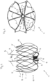
- FIG. 1 shows a cutting pattern for an implant according to alternative (a) in a two-dimensional representation, ie in a cut open and spread out form, before the thermal forming.
- the representation thus shows the originally processed pipe in a two-dimensional representation.
- a plurality of connecting webs 2 emanate from a retaining ring 4, each of which has a plurality of perforations 6 which are used to sew a covering, for example with a Teflon film, onto it.
- the connecting webs 2 each merge into two basket webs 3 which are networked with one another in an intersection plane 11 .
- two basket webs 3 converge to form a rounded tip 5, with the total number of tips 5 forming the ring-shaped distal boundary of the basket 10.
- a hook element 9 is defined by incisions, which forms the barb 9 of the tip 8 in the deformed state.
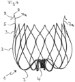
- FIG. 2 shows an implant according to alternative (a) in a lateral photographic representation with the retaining ring 4 and the cage structure 10.
- a plurality of connecting webs 2 proceed from the retaining ring and branch off to the cage structure 10 with their cage webs 3.
- the basket webs 3, which emanate from the connecting webs 2, converge in a plane 11 to branch out again and converge again.
- tips 5 are formed, which are preferably rounded.
- Two spear-shaped anchor elements 7a extend from the retaining ring 4 and form a barb 9 in the region of their tip 8 . These anchoring elements protrude beyond the basket structure 10 and serve to anchor the implant muscle tissue of the auricula sinistra in relation to the entrance.
- the basket structure 10 comes to rest on the walls, the proximal end with the retaining ring 4 is arranged in the entry area.
- the connecting webs 2, which connect the retaining ring 4 to the basket structure 10 and its web elements, have a multiply curved course, such that they first run proximally and are then bent in a semicircle towards the basket 10 distally.
- the webs 2 have perforations 6 for fixing a cover, as in 1 shown.
- Implants according to the invention are connected via the retaining ring 4 with a standard coupling mechanism to a guide catheter, which leads through a catheter to the attending physician. These techniques are well known and widely described. It is also understood that the retaining ring 4 can be closed in a suitable manner to prevent thrombi from being flushed out, for example by fitted elements, struts notched out of the retaining ring or the coupling mechanism fitted into the retaining ring, for example in the form of a plate or ball, which interact with a pincer-shaped retaining element of the guide catheter or wire.
- FIG. 3 shows the implant according to 2 photographed from the proximal side.
- the retaining ring 4 is connected to the actual basket, which is formed by the basket webs 3, via eight connecting webs 2.
- Each connecting web 2 merges into two webs 3 that form the basket in the form of a network.
- the periphery of 3 is formed by the mesh structure of the basket, which terminates distally in the rim formed by the tips 5.
- the connecting webs 2 have a large number of perforations 6 which serve to fix a cover covering the implant, in the case shown by sewing.
- a cover can consist of a Teflon film, for example.
- glue the cover it is also easily possible to glue the cover, to brace it or to connect it to the implant structure by immersion or electrospinning.
- the retaining elements 7a which end in a tip 8, extend centrally from the retaining ring 4.
- the barbs 9 start from the tip 8 and point to the periphery of the basket in the case shown. The cutout from which the barb 9 was released can be seen in the holding element on the left.
- FIG. 4 shows a further variant of an implant according to alternative (a), in which the holding elements 7 with tip 8 and barbs 9 emanate from tips 5 of the crown structure of the implant. Not every tip is connected to a holding element; preferably there are two or four holding elements arranged at regular intervals.
- proximal in the sense of the description designates the side of the implant pointing towards the attending physician and catheter, the term “distal” the side of the implant pointing away from the attending physician and catheter and towards the rear wall of the auricula sinistra.
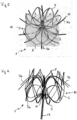
- FIG. 5 shows an implant according to alternative (b) according to the invention.
- the implant 1 has connecting webs 2 emerging from the retaining ring 4 , which branch into the webs 3 which form the actual basket 10 .
- the webs 3 are networked with one another and end in points 5, which are athromatically rounded.
- Variant (b) is characterized by anchor elements 7b, which emanate from the retaining ring 4 between the connecting webs 2 and extend laterally outwards, leaving the region of the basket 10 in the process.
- the anchor elements 7b have a curved course d. H. they are curved proximally. In this way they form a basket that runs in the opposite direction to the basket 10 . They form a ring of arms that hit the wall in the auricula sinistra and thereby fix the implant.
- FIG. 6 shows another photograph of the implant from figure 5 , in this case connected to a guide wire 13, which can be released by twisting after implantation.
- the basket structure formed by the connecting webs 2 and the webs 3 and ending in the tips 5 distal to the guide wire 13 can be clearly seen.
- the anchoring elements 7b start from the retaining ring 4, are arranged between adjacent connecting webs 2 and have a curved profile in such a way that they extend out of the basket 10 to the outside.
- the curvature of the anchor elements 7b causes them to assume an outward and backward (proximal) course in their end region. This is the basis of the locking effect that holds the implant at the implantation site in the auricula sinistra.
- the anchoring elements 7b extend from a holding tube 14, which is fitted into the holding ring 4 at its proximal end and is connected to it.
- the anchor elements 7 b begin at the distal end of the holding tube 14 , of which two adjacent ones are combined to form a loop which ends in a rounded tip 15 .
- the tip of the anchor elements 7b is bent inwards, ie bent back onto the basket.
- the anchoring element 7b is intended to be anchored or braced peripherally with the outside in the auricula sinistra.
- the inwardly curved one Tip 15 of the loop formed by two elements 7b on the one hand prevents damage to the tissue and on the other hand causes tension in the anchor elements 7b, which uses the anchoring of the implant.
- the holding tube 14 can be seen, the proximal end of which is fitted into the holding ring 4 .
- the retaining ring 4 is the starting point of the basket structure 10, which is formed from the webs 2 and 3, the webs 3 being brought together in points 5.
- the anchoring elements 7b start distally from the holding tube 14 and extend laterally beyond the basket structure with a curve towards the proximal side of the implant 1, the ends of the anchoring elements 7b being curved back onto the basket.
- Two adjacent anchor elements 7b each form a loop which ends in a point 15 pointing in the direction of the basket.
- the anchor elements 7b brace themselves peripherally against the wall of the auricula sinistra and thus ensure that the implant is retained at the site of use.
Description
Die Erfindung betrifft medizinisches Implantat zum Verschließen der auricula sinistra eines Patienten auf endovaskulärem Weg, das eine Korbstruktur aus einer Vielzahl von Stegen aufweist, die proximal über Verbindungsstege mit einem Haltering verbunden ist und distal von einem Kranz zusammenlaufender Stege begrenzt ist, wobei das Implantat aus einem selbstexpandierenden Material besteht, in einem kontrahierten Zustand die Form eines geschlitzten Rohrs hat und nach der Expansion eine Korbstruktur mit einem gegenüber dem Haltering erweiterten Durchmesser annimmt.The invention relates to a medical implant for closing the auricula sinistra of a patient in an endovascular way, which has a basket structure made up of a large number of webs, which is connected proximally via connecting webs to a retaining ring and is limited distally by a ring of converging webs, the implant being made of a self-expanding material, having the shape of a slotted tube in a contracted state and, after expansion, assuming a basket structure with a diameter that is larger than that of the retaining ring.
Die auriculae atrii oder Vorhofohren sind Ausstülpungen der Vorhöfe des Herzens bei Säugetieren. Das linke Vorhofohr, medizinisch als auricula sinistra bezeichnet, liegt neben dem Strang der Lungenarterie und ist, insbesondere bei Patienten mit Vorhofflimmern, ein häufiger Entstehungsort für Blutgerinnsel, die zu einem Schlaganfall führen können. Die Verhinderung von Thromben in der auricula sinistra stellt daher eine wirksame Schlaganfallprophylaxe bei gefährdeten Patienten dar.The auriculae atrii or atrial appendages are protuberances of the atria of the heart in mammals. The left atrial appendage, medically known as the left auricula, lies adjacent to the trunk of the pulmonary artery and is a common site for blood clots, particularly in patients with atrial fibrillation, which can lead to a stroke. The prevention of thrombi in the auricula sinistra therefore represents an effective stroke prophylaxis in at-risk patients.
Für diese Schlaganfallprophylaxe wurden Implantate entwickelt, die in den Ausstülpungen eingesetzt werden und den Zugang zumeist über ein Geflecht oder eine Folie verschließen. In der angelsächsischen Literatur werden diese Implantate als LAA-Okkluder bezeichnet (LAA: left atrial appendage). Diese Implantate werden in die Ausstülpungen eingesetzt und dort über Verspannungselemente verankert; sie schließen mit ihrem proximalen Ende den Zugang ab. Die Einbringung erfolgt zumeist über endovaskuläre Techniken d.h. mit einem Katheter, durch den das Implantat in volumenreduzierter Form an den Einsatzort verbracht, dort aus dem Katheter ausgebracht und expandiert wird. Für die Expansion werden in der Regel selbstexpandierende Materialien verwandt, beispielsweise Formgedächtnislegierungen.Implants were developed for this stroke prophylaxis, which are inserted in the protuberances and usually close the access with a mesh or a foil. In Anglo-Saxon literature, these implants are referred to as LAA occluders (LAA: left atrial appendage). These implants are inserted into the protuberances and anchored there using bracing elements; they close off the access with their proximal end. The introduction is mostly via endovascular techniques ie with a catheter through which the implant is brought to the site of use in a reduced-volume form, where it is removed from the catheter and expanded. As a rule, self-expanding materials are used for the expansion, for example shape memory alloys.
Die richtige und zuverlässige Verankerung der Implantate ist häufig ein Problem. Größe und Form der auricula sinistra kann von Patient zu Patient unterschiedlich sein und insbesondere hinsichtlich der Zugangsöffnung enger und weiter ausfallen. Implantate, die durch die Expansion mit den Wandungen der auricula verspannt werden, können deshalb bei nicht optimalem Sitz verrutschen und hierdurch ihren Zweck nicht optimal erfüllen. In solchen Fällen kann es immer noch zur Abschwemmung von Thromben kommen, insbesondere bei körperlicher Belastung des Patienten.The correct and reliable anchoring of the implants is often a problem. The size and shape of the auricula sinistra can vary from patient to patient and can be narrower and wider, especially with regard to the access opening. Implants that are tensioned by the expansion with the walls of the auricula can therefore slip if they are not optimally seated and thus not optimally fulfill their purpose. In such cases, thrombi can still be washed away, especially when the patient is under physical strain.
Angesichts dessen ist es Aufgabe der Erfindung, ein Implantat für die auricula sinistra bereitzustellen, das einen zuverlässigen Sitz und eine optimale Abschirmung gegen den Blutkreislauf gewährleistet.In view of this, it is the object of the invention to provide an implant for the auricula sinistra which ensures a reliable fit and optimal shielding against the blood circulation.
Diese Aufgabe wird mit einem Implant der eingangs genannten Art gelöst, dass ein oder mehrere Ankerelemente aufweist, welche proximal direkt mit dem Haltering verbunden sind, wobei
- a) das oder die Ankerelemente distal eine Spitze mit Widerhaken aufweisen, mit Spitze und Widerhaken über die Korbstruktur hinausragen und dazu bestimmt sind, mit Spitze und Widerhaken im Muskelgewebe der auricula sinistra verankert zu werden, oder
- b) das oder die Ankerelemente lateral über die Korbstruktur hinausragen, nach proximal gekrümmt verlaufen und dazu bestimmt sind, sich gegen das Muskelgewebe der auricula sinistra seitlich abzustützen, oder
- c) eine Kombination der Alternativen (a) und (b).
- a) the anchoring element(s) having a barbed tip distally, protruding with the tip and barb beyond the cage structure and intended to be anchored with the tip and barb in the muscle tissue of the left auricle, or
- b) the anchor element or elements protrude laterally beyond the cage structure, curve in the proximal direction and are intended to be supported laterally against the muscle tissue of the auricula sinistra, or
- c) a combination of alternatives (a) and (b).
Alle Alternativen (a) bis (c) sind geeignet, einen zuverlässigen Sitz des Implantats in der der auricula sinistra zu gewährleisten, dadurch, dass ein Fixierung des Implantats in der der auricula sinistra gegeben ist. Das erfindungsgemäße Implantat deckt lediglich Alternative (b) ab.All of the alternatives (a) to (c) are suitable for ensuring a reliable fit of the implant in the left auricle because the implant is fixed in the left auricle. The implant according to the invention only covers alternative (b).
Das erfindungsgemäße Implantat weist einen Haltering auf, der über eine Mehrzahl von Stegen mit einer distal zum Haltering angeordneten Korbstruktur verbunden ist. Die Korbstruktur ist im expandierten Zustand des Implantats gegenüber dem Haltering stark erweitert. Sie wird von einer Vielzahl von Stegen gebildet, die zweckmäßigerweise eine Maschen- oder Netzstruktur ausbilden. Während die Korbstruktur proximal in dem Haltering ausläuft, ist sie distal offen und wird von einem Kranz zickzackförmig angeordneter und zusammenlaufender Stege begrenzt. Insbesondere besteht die Korbstruktur aus einem Netzwerk von sich verzweigenden und wieder zusammenlaufenden Stegen.The implant according to the invention has a retaining ring which is connected via a plurality of webs to a cage structure arranged distally to the retaining ring. In the expanded state of the implant, the basket structure is greatly expanded compared to the retaining ring. It is formed by a large number of webs, which expediently form a mesh or network structure. While the cage structure ends proximally in the retaining ring, it is open distally and is delimited by a ring of webs arranged in a zigzag shape and converging. In particular, the basket structure consists of a network of webs that branch out and converge again.
Zur Verankerung im Muskelgewebe der auricula sinistra gemäß Alternative (a) weist das Implantat ein oder mehrere Ankerelemente auf, die über die Korbstruktur hinausragen. Jedes Ankerelement endet in einer Spitze mit einem Widerhaken, die dazu bestimmt sind, im Muskelgewebe einzuhaken.For anchoring in the muscle tissue of the auricula sinistra according to alternative (a), the implant has one or more anchor elements that protrude beyond the basket structure. Each anchor element terminates in a barbed tip designed to hook into muscle tissue.
Zur Verankerung in der auricula sinistra gemäß Alternative (b) weist das erfindungsgemäße Implantat mehrere Ankerelemente auf, die lateral aus der Korbstruktur hinausragen, nach proximal gekrümmt verlaufen und dazu bestimmt sind, sich gegen das Muskelgewebe der auricula sinistra seitlich abzustützen. In diesem Fall bilden die Ankerelemente einen zweiten nach proximal offenen Korb, wobei die Enden der Ankerelemente den Rand des Korbes definiert und sich am Muskelgewebe seitlich vom Eingang der auricula sinistra abstützen. Auch in diesem Fall können die Enden der Ankerelemente, gegebenenfalls auch Widerhaken aufweisen, jedoch ist es in der Regel ausreichend, dass die Spitzen abgerundet sind. Auch im letzteren Fall folgt eine sichere Abstützung durch die Verspreizung in der auricula sinistra.For anchoring in the auricula sinistra according to alternative (b), the implant according to the invention has several anchoring elements which protrude laterally from the cage structure, curve proximally and are intended to be laterally supported against the muscle tissue of the auricula sinistra. In this case, the anchoring elements form a second proximally open basket, with the ends of the anchoring elements defining the edge of the basket and being supported on the muscle tissue laterally from the entrance of the auricula sinistra. In this case, too, the ends of the anchor elements can optionally also have barbs, but it is usually sufficient for the tips to be rounded. In the latter case, too, there is secure support through the expansion in the auricula sinistra.
Die Ankerelemente gehen direkt vom Haltering aus und ragen über die Korbstruktur hinaus, sodass sie mit dem Muskelgewebe der auricula sinistra in Kontakt gebracht werden können. Gemäß einer Ausführungsform der Alternative (a) befinden sich das oder die Ankerelemente an den distalen Spitzen des Kranzes der Korbstruktur. Dabei können die Widerhaken nach außen oder nach innen weisen; vorzugsweise sind die Widerhaken an der Außenseite angeordnet. Sind mehrere Ankerelemente vorhanden, sind diese vorzugsweise gleichmäßig über den Kranz verteilt, wobei nicht jede Spitze des Kranzes ein Ankerelement aufweisen muss.The anchoring elements emanate directly from the retaining ring and protrude beyond the basket structure so that they can be brought into contact with the muscle tissue of the left auricle. According to a In the embodiment of alternative (a), the anchor element or elements are located on the distal tips of the rim of the cage structure. The barbs can point outwards or inwards; preferably the barbs are located on the outside. If there are several anchor elements, these are preferably distributed evenly over the rim, with not every point of the rim having to have an anchor element.
Bevorzugt ist aber eine Variante gemäß Alternative (a), bei der das Ankerelement oder jedes Ankerelement von dem Haltering des Implantats ausgeht und durch die Korbstruktur hindurch verläuft und distal über diese hinausragt. Das oder die Ankerelemente befinden sich damit in etwa der Mitte der Korbstruktur. Auch hier ist eine regelmäßige Verteilung der Ankerelemente bevorzugt, sofern mehrere Ankerelemente vorgesehen sind.However, a variant according to alternative (a) is preferred, in which the anchor element or each anchor element starts from the retaining ring of the implant and runs through the cage structure and protrudes distally beyond it. The anchor element or elements are thus located approximately in the middle of the basket structure. Here, too, a regular distribution of the anchor elements is preferred if several anchor elements are provided.
Das erfindungsgemäße medizinische Implantat wird über einen üblichen Katheter an seinen Einsatzort transportiert und dort aus dem Katheter freigesetzt. Im Katheter liegt es in einer volumenreduzierten, kontrahierten und gestreckten Form vor und hat im Wesentlichen die Form eines mehrfach geschlitzten Rohres. Die Form entspricht dem Rohr, aus dem das Implantat durch Laserschneiden erzeugt wurde.The medical implant according to the invention is transported to its place of use via a conventional catheter and released from the catheter there. In the catheter, it is in a reduced-volume, contracted and stretched form and essentially has the shape of a tube with multiple slits. The shape corresponds to the tube from which the implant was created by laser cutting.
Nach der Freisetzung aus dem Katheter nimmt das Implantat die expandierte Form an, die ihm durch ein Temperverfahren aufgeprägt worden ist, d. h. die Korbform mit den darüber hinaus ragenden Ankerelementen.Upon release from the catheter, the implant assumes the expanded shape imparted by an annealing process, i. H. the basket shape with the anchor elements protruding beyond it.
Zur Platzierung ist das im Katheter geführte Implantat über den Haltering mittels eines Kupplungsmechanismus mit einem Führungselement verbunden, vorzugsweise einem Führungskatheter oder -draht. Bei der Implantierung wird das Implantat dann mittels Führungselement in die auricula sinistera hineingeschoben und zur Expansion gebracht. Nach der Expansion sind die im Zentrum der Korbstruktur angeordneten Ankerelemente mit ihren Spitzen und Widerhaken außerhalb des Korbes. Mittels Führungskatheter und/oder Führungsdraht kann der erforderliche Druck ausgeübt werden, um die Spitzen mit den Widerhaken in dem Muskelgewebe an der hinteren Wand der auricula zu verankern. Die Spitzen mit den Widerhaken wachsen problemlos ein und halten das Implantat in der einmal gewählten Stellung zuverlässig fest. Nach der Platzierung wird das Führungselement auf übliche Art und Weise vom Implantat gelöst und zusammen mit dem Katheter zurückgezogen. Derartige Kupplungsmechanismen sind bekannt und vielfach beschrieben.For placement, the implant guided in the catheter is connected to a guide element, preferably a guide catheter or guide wire, via the retaining ring by means of a coupling mechanism. During implantation, the implant is then pushed into the auricula sinistera using a guide element and expanded. After expansion, the anchor elements located in the center of the basket structure are outside the basket with their tips and barbs. The necessary pressure can be exerted by means of a guide catheter and/or guide wire in order to anchor the tips with the barbs in the muscle tissue on the posterior wall of the auricle. The tips with the barbs grow in and out without any problems reliably hold the implant in the selected position. After placement, the guiding element is detached from the implant in the usual manner and withdrawn together with the catheter. Such coupling mechanisms are known and have been described many times.
Die Korbstruktur des erfindungsgemäßen medizinischen Implantats ist in der Regel über 6 bis 12 Verbindungsstege mit dem Haltering verbunden. Bewährt hat sich eine Anzahl von 8 oder 10 Verbindungsstegen, die sich anschließend zur Korbstruktur verzweigen und distal zum abschließenden Kranz erneut vereinigen.The basket structure of the medical implant according to the invention is usually connected to the retaining ring via 6 to 12 connecting webs. A number of 8 or 10 connecting bars, which then branch out to form the cage structure and then unite again distally to form the final rim, has proven effective.
Das erfindungsgemäße Implantat kann bei hinreichender Dichte der Stege seinen Zweck als Thrombenfilter auch ohne eine Abdeckung oder Bespannung erfüllen. Zweckmäßigerweise ist das medizinische Implantat im proximalen Bereich aber mit einer Abdeckung versehen, beispielsweise eine Polyurethan-, Polyester oder Teflonfolie. Um eine solche Abdeckung an der Korbstruktur festzulegen, ist es zweckmäßig, die vom Haltering ausgehenden Verbindungsstege mit Perforationen zu versehen, die zum Vernähen der Abdeckung verwandt werden können. Die Abdeckung kann aber auch durch Verkleben festgelegt werden oder durch (wiederholtes) Tauchen des Implantates in eine Kunststofflösung oder -dispersion erzeugt werden.If the webs are sufficiently dense, the implant according to the invention can fulfill its purpose as a thrombus filter even without a cover or covering. However, the medical implant is expediently provided with a cover in the proximal area, for example a polyurethane, polyester or Teflon film. In order to fix such a cover to the basket structure, it is expedient to provide the connecting webs extending from the retaining ring with perforations that can be used to sew the cover. However, the cover can also be fixed by gluing or by (repeated) immersion of the implant in a plastic solution or dispersion.
Die Implantate weisen vorzugsweise im Inneren des Korbs ein oder mehrere Ankerelemente auf, die, ausgehend vom Haltering (a) speerförmig aus der Öffnung der Korbstruktur herausragen und eine Spitze mit wenigstens einem Widerhaken aufweisen. Spitze und Widerhaken befinden sich außerhalb der Korbstruktur und sind geeignet, bei geeigneter Druckausübung bei der Platzierung mittels Führungsdraht in das Muskelgewebe der auricula sinistra einzudringen und sich dort zu verhaken. Gemäß Alternative (b) ragen die Ankerelemente lateral über die Korbstruktur hinaus und sind nach proximal gekrümmt, so dass sie das Implantat gegen die Seitenwand im Eingangsbereich der auricula sinistra abstützen. Eine Kombination der beiden Varianten (a) und (b) ist ebenfalls möglich. Auf diese Art und Weise wird das Implantat zuverlässig so fixiert, dass sich der proximale Teil des Korbs mit dem Haltering im Eingangsbereich befindet. Der Korb mit oder ohne Abdeckung schirmt damit die auricula sinistra ab und verhindert das Ausschwemmen von Thromben.The implants preferably have one or more anchor elements inside the basket, which, starting from the retaining ring (a), project spear-like out of the opening of the basket structure and have a tip with at least one barb. The tip and barb are located outside of the basket structure and are capable of penetrating and hooking into the muscle tissue of the left auricle when appropriate pressure is applied during placement using the guide wire. According to alternative (b), the anchor elements protrude laterally beyond the cage structure and are curved proximally, so that they support the implant against the side wall in the entry area of the left auricula. A combination of the two variants (a) and (b) is also possible. In this way, the implant is reliably fixed in such a way that the proximal part of the basket with the retaining ring in the entrance area is located. The basket with or without a cover shields the auricula sinistra and prevents thrombi from being flushed out.
Entsprechendes gilt bei Anordnung der Ankerelemente am Korbkranz; in diesem Fall bilden die Ankerelemente das distale Ende des Korbes.The same applies to the arrangement of the anchor elements on the basket rim; in this case the anchor elements form the distal end of the basket.
Im Prinzip ist ein Ankerelement gemäß Alternative (a) ausreichend, vorzugsweise weist das Implantat aber zwei oder mehr Ankerelemente auf, die gleichmäßig über den Umfang des Halterings verteilt sind. Besonders bevorzugt ist eine Anordnung mit zwei Ankerelementen, die einander am Haltering gegenüberstehen. Die Ankerelemente im Zentrum des Korbes verlaufen im Wesentlichen parallel zueinander in etwa der Mitte der Korbstruktur.In principle, one anchor element according to alternative (a) is sufficient, but the implant preferably has two or more anchor elements which are distributed evenly over the circumference of the retaining ring. An arrangement with two anchor elements that face each other on the retaining ring is particularly preferred. The anchor elements in the center of the basket run essentially parallel to one another at about the middle of the basket structure.
Gemäß Alternative (b) ist eine Vielzahl von Ankerelementen zweckmäßig, wobei sie die Zahl an der Zahl der Verbindungsstege zwischen Haltering und Korb orientiert. Auch hier sind die Ankerelemente gleichmäßig über den Umfang des Halterings verteilt. Zweckmäßigerweise sind sie zwischen jeweils zwei Verbindungsstegen angeordnet.According to alternative (b), a large number of anchor elements is expedient, with the number being based on the number of connecting webs between the retaining ring and basket. Here, too, the anchoring elements are distributed evenly over the circumference of the retaining ring. They are expediently arranged between two connecting webs in each case.
Wie schon dargestellt weist die Korbstruktur vorzugsweise ein Netzwerk sich verzweigender und zusammenlaufender Stege auf, die rautenförmige Strukturen ausbilden. Durch zusammenlaufende Stege im distalen Bereich entsteht ein Kranz zusammenlaufender Stege mit zickzackförmigem Verlauf, dessen Spitzen vorzugsweise abgerundet sind. Ein mäandrierender, gerundeter Verlauf ist ebenfalls möglich. Bei Anordnung der Ankerelemente am Kranz ist ein zickzackförmiger Verlauf mit auf die Spitzen des Kranzes aufgesetzten Ankerelementen bevorzugt.As already shown, the basket structure preferably has a network of branching and converging webs that form diamond-shaped structures. Converging webs in the distal area result in a ring of converging webs with a zigzag course, the tips of which are preferably rounded. A meandering, rounded course is also possible. When arranging the anchor elements on the rim, a zigzag course with anchor elements placed on the tips of the rim is preferred.
Am proximalen Ende der Korbstruktur ist der zentrale Haltering vorzugsweise in einer zentralen Eintiefung der Korbstruktur angeordnet. Dies bedeutet, dass die Verbindungsstege zwischen Haltering und Korbstruktur einen S-förmigen verlaufen nehmen, d. h. ausgehend von der distalen Seite des Halterings sich zunächst nach proximal wenden, bevor sie sich erneut nach distal orientieren und in die Korbstruktur übergehen.At the proximal end of the basket structure, the central retaining ring is preferably arranged in a central depression in the basket structure. This means that the connecting webs between the retaining ring and the cage structure run in an S-shape, ie starting from the distal side of the retaining ring they first turn proximally before they orientate themselves distally again and merge into the cage structure.
Gemäß einer weiteren Ausführungsform der Erfindung sind die Ankerelemente distal zur Korbstruktur angeordnet und erstrecken sich lateral über die Korbstruktur hinaus. In diesem Fall gehen die Ankerelemente von einem Halterohr aus, das seinerseits mit dem Haltering der Korbstruktur verbunden ist. Das Halterohr hat zweckmäßigerweise einen etwas geringeren Durchmesser als der Haltering und ist in diesen eingepasst und mit dem Haltering verbunden, etwa verschweißt.According to a further embodiment of the invention, the anchor elements are arranged distally to the cage structure and extend laterally beyond the cage structure. In this case, the anchoring elements emanate from a holding tube, which in turn is connected to the holding ring of the basket structure. The holding tube expediently has a somewhat smaller diameter than the holding ring and is fitted into it and connected to the holding ring, for example welded.
Die Ankerelemente sind in dieser Ausführungsform vorzugsweise paarweise miteinander an den Spitzen verbunden, so dass sie eine Art Schlaufe bilden. Dabei können die Spitzen auf den Korb zurückgebogen sein, so dass sich die Ankerelemente mit ihren Außenflächen an der Peripherie gegen die auricula sinistra verspannen.In this embodiment, the anchor elements are preferably connected to one another in pairs at the tips, so that they form a type of loop. The tips can be bent back onto the basket, so that the anchor elements brace themselves with their outer surfaces on the periphery against the auricula sinistra.
Die erfindungsgemäßen Implantate bestehen aus einen flexiblen, selbst expandierenden Material. Dieses Material kann ein Metall oder ein Kunststoff sein, ist zweckmäßigerweise aber eine Metalllegierung mit Formgedächtniseigenschaften. Besonders bevorzugt sind Nickel-Titan-Legierungen, beispielsweise Nitinol. Die Herstellung von Implantaten aus diesen Materialien und die Umformung durch Tempern sind vielfach beschrieben. Derartige Formgedächtnismetalle sind in der Lage, unter äußerem Zwang die ursprüngliche herstellungsbedingte Form einzunehmen und bei Wegfall dieses Zwangs eine später aufgeprägte Form, die durch Tempern fixiert wird, erneut einzunehmen. Dies erlaubt den Transport solcher Implantate in einem Katheter mit geringem Durchmesser und die anschließende Expansion nach Freisetzung aus dem Katheter.The implants according to the invention consist of a flexible, self-expanding material. This material can be a metal or a plastic, but is suitably a metal alloy with shape memory properties. Nickel-titanium alloys, such as nitinol, are particularly preferred. The production of implants from these materials and the reshaping by tempering have been described many times. Such shape-memory metals are able, under external pressure, to assume the original production-related shape and, when this pressure is removed, to assume a later imprinted shape, which is fixed by tempering, again. This allows such implants to be transported in a small diameter catheter and then expanded upon release from the catheter.
Entsprechend werden auch die erfindungsgemäßen Implantate durch Laserschneiden aus einem Rohr gefertigt und durch anschließendes thermisches Umformen in die expandierte Form gebracht.Correspondingly, the implants according to the invention are also produced from a tube by laser cutting and brought into the expanded form by subsequent thermal forming.
Die erfindungsgemäßen Implantate, wenn aus einer Form Gedächtnislegierung gefertigt, können auch aus zwei Teilen bestehen, die aus separaten Rohren geschnitten werden. So kann aus einem Rohr der Korb gefertigt werden und aus einem zweiten Rohr die Ankerelemente, wobei in jedem Fall ein Haltering vorhanden ist. Die beiden Teile werden zu einem Implantat verbunden, insbesondere verschweißt.The implants of the present invention, when made from one shape shape memory alloy, can also consist of two parts cut from separate tubes. The basket can be made from one tube and the anchor elements from a second tube, with a retaining ring in each case is available. The two parts are connected, in particular welded, to form an implant.
Die Erfindung wird durch die beiliegenden Abbildungen näher erläutert. Es zeigen:
- Fig. 1:
- Ein Schnittmuster für ein Implantat gemäß Alternative (a) in flächiger Darstellung;
- Fig. 2:
- eine seitliche Darstellung eines aus einem Rohr gemäß
Fig. 1 geformten Implantats; - Fig. 3:
- eine Darstellung des Implantats gemäß
Fig. 2 von der proximalen Seite; - Fig. 4:
- eine seitliche Darstellung einer weiteren Ausführungsform eines Implantats gemäß Alternative (a);
- Fig. 5:
- eine fotografische Darstellung einer Ausführungsform eines erfindungs-gemäßen Implantats gemäß Alternative (b);
- Fig. 6:
- eine weitere Fotografie des Implantats gemäß
Fig. 5 , angekoppelt an einen Führungsdraht; - Fig. 7:
- eine weitere Ausführungsform eines erfindungsgemäßen Implantats mit distal zur Korbstruktur angeordneten Ankerelementen; und
- Fig. 8:
- eine seitliche Darstellung des Implantats von
Fig. 7 .
- Figure 1:
- A cutting pattern for an implant according to alternative (a) in a two-dimensional representation;
- Figure 2:
- according to a side view of a from a
tube 1 molded implant; - Figure 3:
- a representation of the implant according to FIG
2 from the proximal side; - Figure 4:
- a side view of a further embodiment of an implant according to alternative (a);
- Figure 5:
- a photographic representation of an embodiment of an inventive implant according to alternative (b);
- Figure 6:
- another photograph of the implant according to
figure 5 , coupled to a guidewire; - Figure 7:
- a further embodiment of an implant according to the invention with anchor elements arranged distally to the cage structure; and
- Figure 8:
- a lateral view of the implant from
Figure 7 .
Von einem Haltering 4 geht eine Mehrzahl von Verbindungsstegen 2 aus, die jeweils mehrere Perforationen 6 zeigen, die dazu dienen, eine Bespannung, beispielsweise mit einer Teflonfolie, daran zu vernähen. Die Verbindungsstege 2 gehen jeweils in zwei Korbstege 3 über, die in einer Kreuzungsebene 11 miteinander vernetzt sind. Im distalen Bereich der Korbstruktur 10 laufen jeweils zwei Korbstege 3 zu einer abgerundeten Spitze 5 zusammen, wobei die Gesamtzahl der Spitzen 5 die kranzförmige distale Begrenzung des Korbs 10 ausbilden.A plurality of connecting
Ausgehend vom Haltering 4 sind zwei Ankerelemente 7a ausgeschnitten, die in einer Spitze 8 enden. Durch Einschnitte wird ein Hakenelement 9 definiert, das in umgeformtem Zustand den Widerhaken 9 der Spitze 8 ausbildet.Starting from the retaining
Vom Haltering 4 gehen zwei speerförmig ausgebildete Ankerelemente 7a aus, die im Bereich ihrer Spitze 8 einen Widerhaken 9 ausbilden. Diese Ankerelemente ragen über die Korbstruktur 10 hinaus und dienen dazu, das Implantatmuskelgewebe der auricula sinistra gegenüber dem Eingang zu verankern. Die Korbstruktur 10 kommt dabei an den Wänden zu liegen, das proximale Ende mit dem Haltering 4 ist im Eingangsbereich angeordnet.Two spear-shaped anchor elements 7a extend from the retaining
Die Verbindungsstege 2, die den Haltering 4 mit der Korbstruktur 10 und seinen Stegelementen verbinden, haben einen mehrfach gekrümmten Verlauf, dergestalt, dass sie zunächst nach proximal verlaufen und anschließend halbkreisförmig zum Korb 10 nach distal umgebogen sind. Die Stege 2 weisen Perforationen 6 zur Festlegung einer Abdeckung auf, wie in
Erfindungsgemäße Implantate sind über den Haltering 4 mit einem üblichen Kupplungsmechanismus mit einem Führungskatheter verbunden, der durch einen Katheter zum behandelnden Arzt führt. Diese Techniken sind allgemein bekannt und vielfach beschrieben. Es versteht sich auch, dass der Haltering 4 zur Verhinderung der Ausschwemmung von Thromben auf eine geeignete Weise verschlossen sein kann, beispielsweise durch eingepasste Elemente, aus dem Haltering ausgeklinkte Streben oder den in den Haltering eingepassten Kupplungsmechanismus, etwa in Form einer Platte oder Kugel, die mit einem zangenförmigen Halteelement des Führungskatheters oder -drahts zusammenwirken.Implants according to the invention are connected via the retaining
Die Verbindungsstege 2 weisen eine Vielzahl von Perforationen 6 aus, die dazu dienen, eine das Implantat bedeckende Abdeckung festzulegen, im gezeigten Fall durch Festnähen. Eine solche Abdeckung kann beispielsweise aus einer Teflonfolie bestehen. Es ist aber ohne Weiteres möglich, die Abdeckung auch zu verkleben, zu verspannen oder durch Tauchen oder Elektrospinnen mit der Implantatstruktur zu verbinden.The connecting
Vom Haltering 4 gehen zentral die Halteelemente 7a aus, die in einer Spitze 8 enden. Die Widerhaken 9 gehen von der Spitze 8 aus und weisen im dargestellten Fall zur Peripherie des Korbs. Zu erkennen ist in dem Halteelement links der Ausschnitt, aus dem der Widerhaken 9 ausgeklinkt wurde.The retaining elements 7a, which end in a
Der Begriff "proximal" im Sinne der Beschreibung bezeichnet die zum behandelnden Arzt und Katheter weisende Seite des Implantats, der Begriff "distal" die vom behandelnden Arzt und Katheter wegweisende und zur hinteren Wand der auricula sinistra weisende Seite des Implantats.The term "proximal" in the sense of the description designates the side of the implant pointing towards the attending physician and catheter, the term "distal" the side of the implant pointing away from the attending physician and catheter and towards the rear wall of the auricula sinistra.
Die Variante (b) zeichnet sich durch Ankerelemente 7b aus, die zwischen den Verbindungsstegen 2 vom Haltering 4 ausgehen und sich lateral nach außen strecken und dabei den Bereich des Korbs 10 verlassen. Die Ankerelemente 7b haben einen gekrümmten Verlauf d. h. sie sind nach proximal gekrümmt. Auf diese Art und Weise bilden sie eine zum Korb 10 gegenläufigen Korb aus. Sie bilden ein Kranz von Armen, die in der auricula sinistra gegen die Wand stoßen und das Implantat dabei fixieren.Variant (b) is characterized by
Die Ankerelemente 7b gehen distal vom Halterohr 14 aus und erstrecken sich lateral über die Korbstruktur hinaus mit einer Krümmung zur proximalen Seite des Implantats 1, wobei die Enden der Ankerelemente 7b auf den Korb zurückgekrümmt sind. Jeweils zwei benachbarte Ankerelemente 7b bilden eine Schlaufe, die in einer in Richtung auf den Korb zeigenden Spitze 15 auslaufen. Die Ankerelemente 7b verspannen sich peripher gegen die Wandung der auricula sinistra und sorgen so für den Erhalt des Implantats am Einsatzort.The
Claims (16)
- Medical implant (1) for the occlusion of a patient's auricula sinistra by endovascular means, said implant having a cage structure (10), the cage structure comprising a plurality of webs (3) that are proximally attached to a retaining ring (4) via connecting webs (2) the cage structure being open distally and limited by a rim of converging webs (3), wherein said implant (1) consists of a self-expanding material, has the shape of a slotted tube in a contracted state and, after expansion, assumes the cage structure (10) of a diameter larger than that of the retaining ring (4), wherein upon expansion several anchor elements (7) are arranged within or distally to the cage structure (10), said anchor elements being proximally connected directly with the retaining ring (4), wherein the anchor elements (7b) project laterally beyond the cage structure (10) and extend in proximal direction in a curved configuration with the intention to be laterally supported against the muscle tissue of the auricula sinistra.
- Implant according to claim 1, wherein the anchor elements (7b) are equally spaced over the circumference of the retaining ring (4).
- Implant according to any one of the preceding claims, wherein the anchor elements (7b) are arranged inside the cage structure and are directly attached to the retaining ring (4).
- Implant according to any one of the preceding claims, wherein the connecting webs (2) extending from retaining ring (4) towards the cage structure (10) are provided with perforations (6).
- Implant according to any one of the preceding claims, wherein the implant further comprises a cover arranged in a proximal region.
- Implant according to claim 5, wherein the cover consists of a Teflon film or coat.
- Implant according to claim 5 or 6, wherein the cover is attached to the cage structure (10) by sewing making use of the perforations.
- Implant according to any one of the preceding claims, wherein the cage structure (10) is composed of a meshwork of branching and converging webs (3).
- Implant according to any one of the preceding claims, wherein the distal rim of the cage structure (10) has rounded tips (5).
- Implant according to any one of the preceding claims, wherein the implant further comprises a coupling for a guide catheter on the retaining ring (4).
- Implant according to any one of the preceding claims, wherein the cage structure (10) is provided in a proximal area with a central deepening portion in which the retaining ring (4) is arranged.
- Implant according to any one of the preceding claims wherein each of the anchor elements (7b) is arranged between two connecting webs (2) at the retaining ring (4).
- Implant according to any one of the preceding claims, wherein the anchor elements (7b) are provided with rounded ends (12).
- Implant according to claim 1, wherein the anchor elements (7b) are arranged distally to the cage structure (10), project laterally beyond the cage structure (10), and are connected to the retaining ring (4) via a retaining tube (14).
- Implant according to claim 14, wherein neighboring anchor elements (7b) are connected with each other in pairs,
wherein the tips of the anchor elements (7b) are bent inwardly pointing towards the cage structure (10). - Implant according to any one of the preceding claims, wherein retaining ring (4), cage structure (10), and anchor elements (7b) consist of a shape-memory metal.
Applications Claiming Priority (2)
| Application Number | Priority Date | Filing Date | Title |
|---|---|---|---|
| DE102013019890.9A DE102013019890A1 (en) | 2013-11-28 | 2013-11-28 | Medical implant |
| PCT/EP2014/075942 WO2015079023A1 (en) | 2013-11-28 | 2014-11-28 | Medical implant |
Publications (2)
| Publication Number | Publication Date |
|---|---|
| EP3073936A1 EP3073936A1 (en) | 2016-10-05 |
| EP3073936B1 true EP3073936B1 (en) | 2023-07-26 |
Family
ID=52232137
Family Applications (1)
| Application Number | Title | Priority Date | Filing Date |
|---|---|---|---|
| EP14820761.6A Active EP3073936B1 (en) | 2013-11-28 | 2014-11-28 | Medical implant |
Country Status (10)
| Country | Link |
|---|---|
| US (1) | US10034786B2 (en) |
| EP (1) | EP3073936B1 (en) |
| JP (1) | JP6527514B2 (en) |
| CN (1) | CN106163425B (en) |
| BR (1) | BR112016012108B1 (en) |
| DE (1) | DE102013019890A1 (en) |
| ES (1) | ES2958514T3 (en) |
| PL (1) | PL3073936T3 (en) |
| RU (1) | RU2688695C1 (en) |
| WO (1) | WO2015079023A1 (en) |
Families Citing this family (12)
| Publication number | Priority date | Publication date | Assignee | Title |
|---|---|---|---|---|
| CN106923884B (en) * | 2015-12-31 | 2018-12-21 | 先健科技(深圳)有限公司 | Occluder for left auricle |
| CN106923883B (en) * | 2015-12-31 | 2019-09-03 | 先健科技(深圳)有限公司 | Occluder for left auricle |
| CN106923886B (en) * | 2015-12-31 | 2022-04-22 | 先健科技(深圳)有限公司 | Left auricle plugging device |
| EP3614933A1 (en) * | 2017-04-27 | 2020-03-04 | Boston Scientific Scimed, Inc. | Occlusive medical device with fabric retention barb |
| EP3403596A1 (en) | 2017-05-16 | 2018-11-21 | Universitätsklinikum Jena | Implantation and anchorage system for an atrial occluder |
| US11173023B2 (en) * | 2017-10-16 | 2021-11-16 | W. L. Gore & Associates, Inc. | Medical devices and anchors therefor |
| CN111867490B (en) * | 2018-02-14 | 2024-01-30 | 波士顿科学医学有限公司 | Occlusion medical device |
| DE102019100531B4 (en) | 2019-01-10 | 2021-08-19 | Qatna Medical GmbH | Occluder delivery system and delivery unit |
| DE102019100530B4 (en) | 2019-01-10 | 2021-05-06 | Qatna Medical GmbH | Occluder and system for introducing an occluder |
| JP2022517224A (en) * | 2019-01-14 | 2022-03-07 | ヴァルフィックス メディカル リミテッド | Anchors and locks for percutaneous valve implants |
| JP2022519720A (en) * | 2019-02-08 | 2022-03-24 | コンフォーマル・メディカル・インコーポレイテッド | Devices and methods for eliminating the left atrial appendage |
| DE102020101456A1 (en) * | 2020-01-22 | 2021-07-22 | Andramed Gmbh | Valvulotome |
Citations (2)
| Publication number | Priority date | Publication date | Assignee | Title |
|---|---|---|---|---|
| WO2012166804A1 (en) * | 2011-06-03 | 2012-12-06 | Reverse Medical Corporation | Embolic implant and method of use |
| EP3120786A1 (en) * | 2013-06-26 | 2017-01-25 | W. L. Gore & Associates, Inc. | Space filling devices |
Family Cites Families (28)
| Publication number | Priority date | Publication date | Assignee | Title |
|---|---|---|---|---|
| US7128073B1 (en) * | 1998-11-06 | 2006-10-31 | Ev3 Endovascular, Inc. | Method and device for left atrial appendage occlusion |
| US6689150B1 (en) * | 1999-10-27 | 2004-02-10 | Atritech, Inc. | Filter apparatus for ostium of left atrial appendage |
| US6994092B2 (en) * | 1999-11-08 | 2006-02-07 | Ev3 Sunnyvale, Inc. | Device for containing embolic material in the LAA having a plurality of tissue retention structures |
| US6962598B2 (en) * | 2001-07-02 | 2005-11-08 | Rubicon Medical, Inc. | Methods, systems, and devices for providing embolic protection |
| JP4328209B2 (en) * | 2002-01-25 | 2009-09-09 | アトリテック, インコーポレイテッド | Atrial appendage blood filtration system |
| US7338530B2 (en) * | 2003-11-24 | 2008-03-04 | Checkmed Systems, Inc. | Stent |
| JP2010527742A (en) * | 2007-05-31 | 2010-08-19 | レックス メディカル リミテッド パートナーシップ | Left atrial appendage closure device |
| US20090171386A1 (en) * | 2007-12-28 | 2009-07-02 | Aga Medical Corporation | Percutaneous catheter directed intravascular occlusion devices |
| EP2389135A2 (en) * | 2008-12-17 | 2011-11-30 | Sanjay Shrivastava | Methods and apparatus for filtering a body lumen |
| DE102009024390A1 (en) * | 2009-06-09 | 2010-12-16 | Bentley Surgical Gmbh | Medical implant for closing vascular openings |
| US10631969B2 (en) * | 2009-06-17 | 2020-04-28 | Coherex Medical, Inc. | Medical device for modification of left atrial appendage and related systems and methods |
| WO2010148246A2 (en) * | 2009-06-17 | 2010-12-23 | Coherex Medical, Inc. | Medical device for modification of left atrial appendage and related systems and methods |
| US9649115B2 (en) * | 2009-06-17 | 2017-05-16 | Coherex Medical, Inc. | Medical device for modification of left atrial appendage and related systems and methods |
| US20110054515A1 (en) * | 2009-08-25 | 2011-03-03 | John Bridgeman | Device and method for occluding the left atrial appendage |
| US10433956B2 (en) * | 2010-02-24 | 2019-10-08 | Medtronic Ventor Technologies Ltd. | Mitral prosthesis and methods for implantation |
| US8579964B2 (en) * | 2010-05-05 | 2013-11-12 | Neovasc Inc. | Transcatheter mitral valve prosthesis |
| JP5995110B2 (en) * | 2010-10-21 | 2016-09-21 | メドトロニック,インコーポレイテッド | Intraventricular low profile prosthetic mitral valve |
| CN202143640U (en) * | 2011-06-01 | 2012-02-15 | 先健科技(深圳)有限公司 | Left atrial appendage occluder |
| US9554806B2 (en) * | 2011-09-16 | 2017-01-31 | W. L. Gore & Associates, Inc. | Occlusive devices |
| CN202335893U (en) * | 2011-10-31 | 2012-07-18 | 上海形状记忆合金材料有限公司 | Left aurcle plugging device |
| CN104168843B (en) * | 2011-11-01 | 2017-03-08 | 科赫里克斯医疗股份有限公司 | For revising the medical treatment device of left auricle and the system and method for correlation |
| CA2848602C (en) * | 2011-11-09 | 2016-10-11 | Boston Scientific Scimed, Inc. | Occlusion device |
| EP2838444A4 (en) * | 2012-04-20 | 2016-02-24 | Inceptus Medical LLC | Expandable occlusion devices and methods of use |
| US20140135817A1 (en) * | 2012-11-14 | 2014-05-15 | Boston Scientific Scimed, Inc. | Left atrial appendage closure implant |
| RU128101U1 (en) * | 2012-12-17 | 2013-05-20 | Общество с ограниченной ответственностью "Ангиолайн интервеншионал девайс" | OKCLUDER |
| US11911258B2 (en) * | 2013-06-26 | 2024-02-27 | W. L. Gore & Associates, Inc. | Space filling devices |
| CN106413589A (en) * | 2014-06-11 | 2017-02-15 | 奥特鲁泰克控股有限公司 | Left atrial appendage occluder |
| DE102015104785A1 (en) * | 2015-03-27 | 2016-09-29 | Pfm Medical Ag | Device for closing a cardiac ear |
-
2013
- 2013-11-28 DE DE102013019890.9A patent/DE102013019890A1/en active Pending
-
2014
- 2014-11-28 JP JP2016534927A patent/JP6527514B2/en active Active
- 2014-11-28 ES ES14820761T patent/ES2958514T3/en active Active
- 2014-11-28 US US15/039,331 patent/US10034786B2/en active Active
- 2014-11-28 CN CN201480073257.8A patent/CN106163425B/en active Active
- 2014-11-28 RU RU2016125511A patent/RU2688695C1/en active
- 2014-11-28 PL PL14820761.6T patent/PL3073936T3/en unknown
- 2014-11-28 EP EP14820761.6A patent/EP3073936B1/en active Active
- 2014-11-28 WO PCT/EP2014/075942 patent/WO2015079023A1/en active Application Filing
- 2014-11-28 BR BR112016012108-2A patent/BR112016012108B1/en active IP Right Grant
Patent Citations (2)
| Publication number | Priority date | Publication date | Assignee | Title |
|---|---|---|---|---|
| WO2012166804A1 (en) * | 2011-06-03 | 2012-12-06 | Reverse Medical Corporation | Embolic implant and method of use |
| EP3120786A1 (en) * | 2013-06-26 | 2017-01-25 | W. L. Gore & Associates, Inc. | Space filling devices |
Also Published As
| Publication number | Publication date |
|---|---|
| JP2017503538A (en) | 2017-02-02 |
| BR112016012108B1 (en) | 2022-03-03 |
| ES2958514T3 (en) | 2024-02-09 |
| BR112016012108A2 (en) | 2017-08-08 |
| US20170156898A1 (en) | 2017-06-08 |
| EP3073936A1 (en) | 2016-10-05 |
| DE102013019890A1 (en) | 2015-05-28 |
| PL3073936T3 (en) | 2024-02-05 |
| CN106163425A (en) | 2016-11-23 |
| WO2015079023A1 (en) | 2015-06-04 |
| JP6527514B2 (en) | 2019-06-05 |
| CN106163425B (en) | 2022-01-07 |
| US10034786B2 (en) | 2018-07-31 |
| RU2688695C1 (en) | 2019-05-22 |
| RU2016125511A (en) | 2018-01-10 |
Similar Documents
| Publication | Publication Date | Title |
|---|---|---|
| EP3073936B1 (en) | Medical implant | |
| EP2259728B1 (en) | Device for closing defects in the vascular system | |
| EP1948030B1 (en) | Occlusion instrument for closing a cardiac auricle | |
| EP2571431B1 (en) | Medical device for removing concretions | |
| DE69533985T2 (en) | STENT | |
| EP1648342B1 (en) | Woven stent to be implanted in a blood vessel | |
| EP2706929B9 (en) | Thrombectomy device | |
| DE60031413T2 (en) | NITINOL MEDICAL DEVICES WITH EFFECTIVE VARIABLE STIFFNESS THROUGH HEAT TREATMENT | |
| DE69633824T2 (en) | DEVICE FOR IMPLANTING IN A BLOOD TANK RELATING TO A HOLLOWED BODY LUMEN | |
| EP1667608B1 (en) | Stent comprising terminal anchoring elements | |
| DE29825257U1 (en) | Percutaneous catheter-guided closure devices | |
| WO2014026870A2 (en) | Implantable device for use in the human and/or animal body to replace an organ valve | |
| EP1722695A1 (en) | Device for rechannelling a cavity, organ path or vessel | |
| EP3273874B1 (en) | Device for closing an atrial appendage | |
| EP2698130B1 (en) | Method for producing a body implant | |
| DE202007005491U1 (en) | Medical device for treating aortic valve insufficiency of patient, has self-expandable endoprosthesis for positioning and fixing heart valve implant in arota of patient, and retaining segment with brackets for receiving implant | |
| DE102010035543A1 (en) | Medical device and system with such a device | |
| EP2995282A1 (en) | Preformed stent | |
| EP3764928B1 (en) | Thrombectomy device | |
| DE102012107175B4 (en) | Medical closure device and system with such a closure device | |
| EP3389511B1 (en) | Implant | |
| EP3320862B1 (en) | Device for positioning and release of a closure implant for closing the left atrial auricle | |
| DE202020107453U1 (en) | Stent, in particular for the treatment of diseases of the carotid artery | |
| DE20314392U1 (en) | Flexible stent, for insertion into blood vessels and the like, has projecting bent anchors at the ends of the stent, in a structure with length stability at sites near the heart and in branch vessels | |
| EP3773357A1 (en) | Bifurcated stent and stent system |
Legal Events
| Date | Code | Title | Description |
|---|---|---|---|
| PUAI | Public reference made under article 153(3) epc to a published international application that has entered the european phase |
Free format text: ORIGINAL CODE: 0009012 |
|
| 17P | Request for examination filed |
Effective date: 20160628 |
|
| AK | Designated contracting states |
Kind code of ref document: A1 Designated state(s): AL AT BE BG CH CY CZ DE DK EE ES FI FR GB GR HR HU IE IS IT LI LT LU LV MC MK MT NL NO PL PT RO RS SE SI SK SM TR |
|
| AX | Request for extension of the european patent |
Extension state: BA ME |
|
| RIN1 | Information on inventor provided before grant (corrected) |
Inventor name: OBRADOVIC, MILISAV |
|
| DAX | Request for extension of the european patent (deleted) | ||
| STAA | Information on the status of an ep patent application or granted ep patent |
Free format text: STATUS: EXAMINATION IS IN PROGRESS |
|
| 17Q | First examination report despatched |
Effective date: 20171108 |
|
| RAP1 | Party data changed (applicant data changed or rights of an application transferred) |
Owner name: BENTLEY INNOMED GMBH |
|
| STAA | Information on the status of an ep patent application or granted ep patent |
Free format text: STATUS: EXAMINATION IS IN PROGRESS |
|
| GRAP | Despatch of communication of intention to grant a patent |
Free format text: ORIGINAL CODE: EPIDOSNIGR1 |
|
| STAA | Information on the status of an ep patent application or granted ep patent |
Free format text: STATUS: GRANT OF PATENT IS INTENDED |
|
| RIC1 | Information provided on ipc code assigned before grant |
Ipc: A61B 17/00 20060101ALN20230201BHEP Ipc: A61B 17/12 20060101AFI20230201BHEP |
|
| INTG | Intention to grant announced |
Effective date: 20230215 |
|
| GRAS | Grant fee paid |
Free format text: ORIGINAL CODE: EPIDOSNIGR3 |
|
| GRAA | (expected) grant |
Free format text: ORIGINAL CODE: 0009210 |
|
| STAA | Information on the status of an ep patent application or granted ep patent |
Free format text: STATUS: THE PATENT HAS BEEN GRANTED |
|
| AK | Designated contracting states |
Kind code of ref document: B1 Designated state(s): AL AT BE BG CH CY CZ DE DK EE ES FI FR GB GR HR HU IE IS IT LI LT LU LV MC MK MT NL NO PL PT RO RS SE SI SK SM TR |
|
| REG | Reference to a national code |
Ref country code: CH Ref legal event code: EP |
|
| REG | Reference to a national code |
Ref country code: IE Ref legal event code: FG4D Free format text: LANGUAGE OF EP DOCUMENT: GERMAN |
|
| REG | Reference to a national code |
Ref country code: DE Ref legal event code: R096 Ref document number: 502014016641 Country of ref document: DE |
|
| REG | Reference to a national code |
Ref country code: NL Ref legal event code: FP |
|
| REG | Reference to a national code |
Ref country code: LT Ref legal event code: MG9D |
|
| PGFP | Annual fee paid to national office [announced via postgrant information from national office to epo] |
Ref country code: NL Payment date: 20231122 Year of fee payment: 10 |
|
| PG25 | Lapsed in a contracting state [announced via postgrant information from national office to epo] |
Ref country code: GR Free format text: LAPSE BECAUSE OF FAILURE TO SUBMIT A TRANSLATION OF THE DESCRIPTION OR TO PAY THE FEE WITHIN THE PRESCRIBED TIME-LIMIT Effective date: 20231027 |
|
| PGFP | Annual fee paid to national office [announced via postgrant information from national office to epo] |
Ref country code: ES Payment date: 20231215 Year of fee payment: 10 |
|
| PG25 | Lapsed in a contracting state [announced via postgrant information from national office to epo] |
Ref country code: IS Free format text: LAPSE BECAUSE OF FAILURE TO SUBMIT A TRANSLATION OF THE DESCRIPTION OR TO PAY THE FEE WITHIN THE PRESCRIBED TIME-LIMIT Effective date: 20231126 |
|
| PG25 | Lapsed in a contracting state [announced via postgrant information from national office to epo] |
Ref country code: SE Free format text: LAPSE BECAUSE OF FAILURE TO SUBMIT A TRANSLATION OF THE DESCRIPTION OR TO PAY THE FEE WITHIN THE PRESCRIBED TIME-LIMIT Effective date: 20230726 Ref country code: RS Free format text: LAPSE BECAUSE OF FAILURE TO SUBMIT A TRANSLATION OF THE DESCRIPTION OR TO PAY THE FEE WITHIN THE PRESCRIBED TIME-LIMIT Effective date: 20230726 Ref country code: PT Free format text: LAPSE BECAUSE OF FAILURE TO SUBMIT A TRANSLATION OF THE DESCRIPTION OR TO PAY THE FEE WITHIN THE PRESCRIBED TIME-LIMIT Effective date: 20231127 Ref country code: NO Free format text: LAPSE BECAUSE OF FAILURE TO SUBMIT A TRANSLATION OF THE DESCRIPTION OR TO PAY THE FEE WITHIN THE PRESCRIBED TIME-LIMIT Effective date: 20231026 Ref country code: LV Free format text: LAPSE BECAUSE OF FAILURE TO SUBMIT A TRANSLATION OF THE DESCRIPTION OR TO PAY THE FEE WITHIN THE PRESCRIBED TIME-LIMIT Effective date: 20230726 Ref country code: LT Free format text: LAPSE BECAUSE OF FAILURE TO SUBMIT A TRANSLATION OF THE DESCRIPTION OR TO PAY THE FEE WITHIN THE PRESCRIBED TIME-LIMIT Effective date: 20230726 Ref country code: IS Free format text: LAPSE BECAUSE OF FAILURE TO SUBMIT A TRANSLATION OF THE DESCRIPTION OR TO PAY THE FEE WITHIN THE PRESCRIBED TIME-LIMIT Effective date: 20231126 Ref country code: HR Free format text: LAPSE BECAUSE OF FAILURE TO SUBMIT A TRANSLATION OF THE DESCRIPTION OR TO PAY THE FEE WITHIN THE PRESCRIBED TIME-LIMIT Effective date: 20230726 Ref country code: GR Free format text: LAPSE BECAUSE OF FAILURE TO SUBMIT A TRANSLATION OF THE DESCRIPTION OR TO PAY THE FEE WITHIN THE PRESCRIBED TIME-LIMIT Effective date: 20231027 Ref country code: FI Free format text: LAPSE BECAUSE OF FAILURE TO SUBMIT A TRANSLATION OF THE DESCRIPTION OR TO PAY THE FEE WITHIN THE PRESCRIBED TIME-LIMIT Effective date: 20230726 |
|
| PGFP | Annual fee paid to national office [announced via postgrant information from national office to epo] |
Ref country code: IT Payment date: 20231130 Year of fee payment: 10 Ref country code: IE Payment date: 20231117 Year of fee payment: 10 Ref country code: DE Payment date: 20231130 Year of fee payment: 10 Ref country code: AT Payment date: 20231117 Year of fee payment: 10 |
|
| REG | Reference to a national code |
Ref country code: ES Ref legal event code: FG2A Ref document number: 2958514 Country of ref document: ES Kind code of ref document: T3 Effective date: 20240209 |