EP3073546A1 - Bloc-batteries - Google Patents
Bloc-batteries Download PDFInfo
- Publication number
- EP3073546A1 EP3073546A1 EP16159859.4A EP16159859A EP3073546A1 EP 3073546 A1 EP3073546 A1 EP 3073546A1 EP 16159859 A EP16159859 A EP 16159859A EP 3073546 A1 EP3073546 A1 EP 3073546A1
- Authority
- EP
- European Patent Office
- Prior art keywords
- battery modules
- battery
- chamber
- battery pack
- thermal diffusing
- Prior art date
- Legal status (The legal status is an assumption and is not a legal conclusion. Google has not performed a legal analysis and makes no representation as to the accuracy of the status listed.)
- Granted
Links
- 238000001816 cooling Methods 0.000 claims abstract description 24
- 239000000779 smoke Substances 0.000 claims description 9
- 229910052782 aluminium Inorganic materials 0.000 claims description 8
- XAGFODPZIPBFFR-UHFFFAOYSA-N aluminium Chemical compound [Al] XAGFODPZIPBFFR-UHFFFAOYSA-N 0.000 claims description 8
- 229910052751 metal Inorganic materials 0.000 claims description 4
- 239000002184 metal Substances 0.000 claims description 4
- 239000000126 substance Substances 0.000 claims description 2
- 239000011347 resin Substances 0.000 description 7
- 229920005989 resin Polymers 0.000 description 7
- 238000010438 heat treatment Methods 0.000 description 6
- 239000007769 metal material Substances 0.000 description 2
- 238000000034 method Methods 0.000 description 2
- HBBGRARXTFLTSG-UHFFFAOYSA-N Lithium ion Chemical compound [Li+] HBBGRARXTFLTSG-UHFFFAOYSA-N 0.000 description 1
- 241000276425 Xiphophorus maculatus Species 0.000 description 1
- 239000000853 adhesive Substances 0.000 description 1
- 230000000712 assembly Effects 0.000 description 1
- 238000000429 assembly Methods 0.000 description 1
- 230000000694 effects Effects 0.000 description 1
- 238000009434 installation Methods 0.000 description 1
- 229910001416 lithium ion Inorganic materials 0.000 description 1
- 229910052987 metal hydride Inorganic materials 0.000 description 1
- 238000012986 modification Methods 0.000 description 1
- 230000004048 modification Effects 0.000 description 1
- 238000000465 moulding Methods 0.000 description 1
- 238000005192 partition Methods 0.000 description 1
- 230000003014 reinforcing effect Effects 0.000 description 1
- 238000000926 separation method Methods 0.000 description 1
Images


Classifications
-
- B—PERFORMING OPERATIONS; TRANSPORTING
- B60—VEHICLES IN GENERAL
- B60K—ARRANGEMENT OR MOUNTING OF PROPULSION UNITS OR OF TRANSMISSIONS IN VEHICLES; ARRANGEMENT OR MOUNTING OF PLURAL DIVERSE PRIME-MOVERS IN VEHICLES; AUXILIARY DRIVES FOR VEHICLES; INSTRUMENTATION OR DASHBOARDS FOR VEHICLES; ARRANGEMENTS IN CONNECTION WITH COOLING, AIR INTAKE, GAS EXHAUST OR FUEL SUPPLY OF PROPULSION UNITS IN VEHICLES
- B60K1/00—Arrangement or mounting of electrical propulsion units
- B60K1/04—Arrangement or mounting of electrical propulsion units of the electric storage means for propulsion
-
- B—PERFORMING OPERATIONS; TRANSPORTING
- B60—VEHICLES IN GENERAL
- B60L—PROPULSION OF ELECTRICALLY-PROPELLED VEHICLES; SUPPLYING ELECTRIC POWER FOR AUXILIARY EQUIPMENT OF ELECTRICALLY-PROPELLED VEHICLES; ELECTRODYNAMIC BRAKE SYSTEMS FOR VEHICLES IN GENERAL; MAGNETIC SUSPENSION OR LEVITATION FOR VEHICLES; MONITORING OPERATING VARIABLES OF ELECTRICALLY-PROPELLED VEHICLES; ELECTRIC SAFETY DEVICES FOR ELECTRICALLY-PROPELLED VEHICLES
- B60L50/00—Electric propulsion with power supplied within the vehicle
- B60L50/50—Electric propulsion with power supplied within the vehicle using propulsion power supplied by batteries or fuel cells
- B60L50/60—Electric propulsion with power supplied within the vehicle using propulsion power supplied by batteries or fuel cells using power supplied by batteries
- B60L50/64—Constructional details of batteries specially adapted for electric vehicles
-
- B—PERFORMING OPERATIONS; TRANSPORTING
- B60—VEHICLES IN GENERAL
- B60L—PROPULSION OF ELECTRICALLY-PROPELLED VEHICLES; SUPPLYING ELECTRIC POWER FOR AUXILIARY EQUIPMENT OF ELECTRICALLY-PROPELLED VEHICLES; ELECTRODYNAMIC BRAKE SYSTEMS FOR VEHICLES IN GENERAL; MAGNETIC SUSPENSION OR LEVITATION FOR VEHICLES; MONITORING OPERATING VARIABLES OF ELECTRICALLY-PROPELLED VEHICLES; ELECTRIC SAFETY DEVICES FOR ELECTRICALLY-PROPELLED VEHICLES
- B60L50/00—Electric propulsion with power supplied within the vehicle
- B60L50/50—Electric propulsion with power supplied within the vehicle using propulsion power supplied by batteries or fuel cells
- B60L50/60—Electric propulsion with power supplied within the vehicle using propulsion power supplied by batteries or fuel cells using power supplied by batteries
- B60L50/66—Arrangements of batteries
-
- B—PERFORMING OPERATIONS; TRANSPORTING
- B60—VEHICLES IN GENERAL
- B60L—PROPULSION OF ELECTRICALLY-PROPELLED VEHICLES; SUPPLYING ELECTRIC POWER FOR AUXILIARY EQUIPMENT OF ELECTRICALLY-PROPELLED VEHICLES; ELECTRODYNAMIC BRAKE SYSTEMS FOR VEHICLES IN GENERAL; MAGNETIC SUSPENSION OR LEVITATION FOR VEHICLES; MONITORING OPERATING VARIABLES OF ELECTRICALLY-PROPELLED VEHICLES; ELECTRIC SAFETY DEVICES FOR ELECTRICALLY-PROPELLED VEHICLES
- B60L58/00—Methods or circuit arrangements for monitoring or controlling batteries or fuel cells, specially adapted for electric vehicles
- B60L58/10—Methods or circuit arrangements for monitoring or controlling batteries or fuel cells, specially adapted for electric vehicles for monitoring or controlling batteries
- B60L58/24—Methods or circuit arrangements for monitoring or controlling batteries or fuel cells, specially adapted for electric vehicles for monitoring or controlling batteries for controlling the temperature of batteries
- B60L58/27—Methods or circuit arrangements for monitoring or controlling batteries or fuel cells, specially adapted for electric vehicles for monitoring or controlling batteries for controlling the temperature of batteries by heating
-
- H—ELECTRICITY
- H01—ELECTRIC ELEMENTS
- H01M—PROCESSES OR MEANS, e.g. BATTERIES, FOR THE DIRECT CONVERSION OF CHEMICAL ENERGY INTO ELECTRICAL ENERGY
- H01M10/00—Secondary cells; Manufacture thereof
- H01M10/60—Heating or cooling; Temperature control
- H01M10/61—Types of temperature control
- H01M10/613—Cooling or keeping cold
-
- H—ELECTRICITY
- H01—ELECTRIC ELEMENTS
- H01M—PROCESSES OR MEANS, e.g. BATTERIES, FOR THE DIRECT CONVERSION OF CHEMICAL ENERGY INTO ELECTRICAL ENERGY
- H01M10/00—Secondary cells; Manufacture thereof
- H01M10/60—Heating or cooling; Temperature control
- H01M10/61—Types of temperature control
- H01M10/615—Heating or keeping warm
-
- H—ELECTRICITY
- H01—ELECTRIC ELEMENTS
- H01M—PROCESSES OR MEANS, e.g. BATTERIES, FOR THE DIRECT CONVERSION OF CHEMICAL ENERGY INTO ELECTRICAL ENERGY
- H01M10/00—Secondary cells; Manufacture thereof
- H01M10/60—Heating or cooling; Temperature control
- H01M10/61—Types of temperature control
- H01M10/617—Types of temperature control for achieving uniformity or desired distribution of temperature
-
- H—ELECTRICITY
- H01—ELECTRIC ELEMENTS
- H01M—PROCESSES OR MEANS, e.g. BATTERIES, FOR THE DIRECT CONVERSION OF CHEMICAL ENERGY INTO ELECTRICAL ENERGY
- H01M10/00—Secondary cells; Manufacture thereof
- H01M10/60—Heating or cooling; Temperature control
- H01M10/62—Heating or cooling; Temperature control specially adapted for specific applications
- H01M10/625—Vehicles
-
- H—ELECTRICITY
- H01—ELECTRIC ELEMENTS
- H01M—PROCESSES OR MEANS, e.g. BATTERIES, FOR THE DIRECT CONVERSION OF CHEMICAL ENERGY INTO ELECTRICAL ENERGY
- H01M10/00—Secondary cells; Manufacture thereof
- H01M10/60—Heating or cooling; Temperature control
- H01M10/64—Heating or cooling; Temperature control characterised by the shape of the cells
- H01M10/643—Cylindrical cells
-
- H—ELECTRICITY
- H01—ELECTRIC ELEMENTS
- H01M—PROCESSES OR MEANS, e.g. BATTERIES, FOR THE DIRECT CONVERSION OF CHEMICAL ENERGY INTO ELECTRICAL ENERGY
- H01M10/00—Secondary cells; Manufacture thereof
- H01M10/60—Heating or cooling; Temperature control
- H01M10/65—Means for temperature control structurally associated with the cells
- H01M10/655—Solid structures for heat exchange or heat conduction
- H01M10/6554—Rods or plates
- H01M10/6555—Rods or plates arranged between the cells
-
- H—ELECTRICITY
- H01—ELECTRIC ELEMENTS
- H01M—PROCESSES OR MEANS, e.g. BATTERIES, FOR THE DIRECT CONVERSION OF CHEMICAL ENERGY INTO ELECTRICAL ENERGY
- H01M10/00—Secondary cells; Manufacture thereof
- H01M10/60—Heating or cooling; Temperature control
- H01M10/65—Means for temperature control structurally associated with the cells
- H01M10/655—Solid structures for heat exchange or heat conduction
- H01M10/6556—Solid parts with flow channel passages or pipes for heat exchange
- H01M10/6557—Solid parts with flow channel passages or pipes for heat exchange arranged between the cells
-
- H—ELECTRICITY
- H01—ELECTRIC ELEMENTS
- H01M—PROCESSES OR MEANS, e.g. BATTERIES, FOR THE DIRECT CONVERSION OF CHEMICAL ENERGY INTO ELECTRICAL ENERGY
- H01M10/00—Secondary cells; Manufacture thereof
- H01M10/60—Heating or cooling; Temperature control
- H01M10/65—Means for temperature control structurally associated with the cells
- H01M10/656—Means for temperature control structurally associated with the cells characterised by the type of heat-exchange fluid
- H01M10/6561—Gases
-
- H—ELECTRICITY
- H01—ELECTRIC ELEMENTS
- H01M—PROCESSES OR MEANS, e.g. BATTERIES, FOR THE DIRECT CONVERSION OF CHEMICAL ENERGY INTO ELECTRICAL ENERGY
- H01M10/00—Secondary cells; Manufacture thereof
- H01M10/60—Heating or cooling; Temperature control
- H01M10/65—Means for temperature control structurally associated with the cells
- H01M10/657—Means for temperature control structurally associated with the cells by electric or electromagnetic means
- H01M10/6571—Resistive heaters
-
- H—ELECTRICITY
- H01—ELECTRIC ELEMENTS
- H01M—PROCESSES OR MEANS, e.g. BATTERIES, FOR THE DIRECT CONVERSION OF CHEMICAL ENERGY INTO ELECTRICAL ENERGY
- H01M50/00—Constructional details or processes of manufacture of the non-active parts of electrochemical cells other than fuel cells, e.g. hybrid cells
- H01M50/20—Mountings; Secondary casings or frames; Racks, modules or packs; Suspension devices; Shock absorbers; Transport or carrying devices; Holders
- H01M50/204—Racks, modules or packs for multiple batteries or multiple cells
- H01M50/207—Racks, modules or packs for multiple batteries or multiple cells characterised by their shape
- H01M50/213—Racks, modules or packs for multiple batteries or multiple cells characterised by their shape adapted for cells having curved cross-section, e.g. round or elliptic
-
- H—ELECTRICITY
- H01—ELECTRIC ELEMENTS
- H01M—PROCESSES OR MEANS, e.g. BATTERIES, FOR THE DIRECT CONVERSION OF CHEMICAL ENERGY INTO ELECTRICAL ENERGY
- H01M50/00—Constructional details or processes of manufacture of the non-active parts of electrochemical cells other than fuel cells, e.g. hybrid cells
- H01M50/20—Mountings; Secondary casings or frames; Racks, modules or packs; Suspension devices; Shock absorbers; Transport or carrying devices; Holders
- H01M50/271—Lids or covers for the racks or secondary casings
-
- B—PERFORMING OPERATIONS; TRANSPORTING
- B60—VEHICLES IN GENERAL
- B60K—ARRANGEMENT OR MOUNTING OF PROPULSION UNITS OR OF TRANSMISSIONS IN VEHICLES; ARRANGEMENT OR MOUNTING OF PLURAL DIVERSE PRIME-MOVERS IN VEHICLES; AUXILIARY DRIVES FOR VEHICLES; INSTRUMENTATION OR DASHBOARDS FOR VEHICLES; ARRANGEMENTS IN CONNECTION WITH COOLING, AIR INTAKE, GAS EXHAUST OR FUEL SUPPLY OF PROPULSION UNITS IN VEHICLES
- B60K1/00—Arrangement or mounting of electrical propulsion units
- B60K1/04—Arrangement or mounting of electrical propulsion units of the electric storage means for propulsion
- B60K2001/0405—Arrangement or mounting of electrical propulsion units of the electric storage means for propulsion characterised by their position
- B60K2001/0416—Arrangement in the rear part of the vehicle
-
- B—PERFORMING OPERATIONS; TRANSPORTING
- B60—VEHICLES IN GENERAL
- B60K—ARRANGEMENT OR MOUNTING OF PROPULSION UNITS OR OF TRANSMISSIONS IN VEHICLES; ARRANGEMENT OR MOUNTING OF PLURAL DIVERSE PRIME-MOVERS IN VEHICLES; AUXILIARY DRIVES FOR VEHICLES; INSTRUMENTATION OR DASHBOARDS FOR VEHICLES; ARRANGEMENTS IN CONNECTION WITH COOLING, AIR INTAKE, GAS EXHAUST OR FUEL SUPPLY OF PROPULSION UNITS IN VEHICLES
- B60K1/00—Arrangement or mounting of electrical propulsion units
- B60K1/04—Arrangement or mounting of electrical propulsion units of the electric storage means for propulsion
- B60K2001/0405—Arrangement or mounting of electrical propulsion units of the electric storage means for propulsion characterised by their position
- B60K2001/0422—Arrangement under the front seats
-
- B—PERFORMING OPERATIONS; TRANSPORTING
- B60—VEHICLES IN GENERAL
- B60K—ARRANGEMENT OR MOUNTING OF PROPULSION UNITS OR OF TRANSMISSIONS IN VEHICLES; ARRANGEMENT OR MOUNTING OF PLURAL DIVERSE PRIME-MOVERS IN VEHICLES; AUXILIARY DRIVES FOR VEHICLES; INSTRUMENTATION OR DASHBOARDS FOR VEHICLES; ARRANGEMENTS IN CONNECTION WITH COOLING, AIR INTAKE, GAS EXHAUST OR FUEL SUPPLY OF PROPULSION UNITS IN VEHICLES
- B60K1/00—Arrangement or mounting of electrical propulsion units
- B60K1/04—Arrangement or mounting of electrical propulsion units of the electric storage means for propulsion
- B60K2001/0405—Arrangement or mounting of electrical propulsion units of the electric storage means for propulsion characterised by their position
- B60K2001/0433—Arrangement under the rear seats
-
- B—PERFORMING OPERATIONS; TRANSPORTING
- B60—VEHICLES IN GENERAL
- B60L—PROPULSION OF ELECTRICALLY-PROPELLED VEHICLES; SUPPLYING ELECTRIC POWER FOR AUXILIARY EQUIPMENT OF ELECTRICALLY-PROPELLED VEHICLES; ELECTRODYNAMIC BRAKE SYSTEMS FOR VEHICLES IN GENERAL; MAGNETIC SUSPENSION OR LEVITATION FOR VEHICLES; MONITORING OPERATING VARIABLES OF ELECTRICALLY-PROPELLED VEHICLES; ELECTRIC SAFETY DEVICES FOR ELECTRICALLY-PROPELLED VEHICLES
- B60L2240/00—Control parameters of input or output; Target parameters
- B60L2240/40—Drive Train control parameters
- B60L2240/54—Drive Train control parameters related to batteries
- B60L2240/545—Temperature
-
- H—ELECTRICITY
- H01—ELECTRIC ELEMENTS
- H01M—PROCESSES OR MEANS, e.g. BATTERIES, FOR THE DIRECT CONVERSION OF CHEMICAL ENERGY INTO ELECTRICAL ENERGY
- H01M2220/00—Batteries for particular applications
- H01M2220/20—Batteries in motive systems, e.g. vehicle, ship, plane
-
- Y—GENERAL TAGGING OF NEW TECHNOLOGICAL DEVELOPMENTS; GENERAL TAGGING OF CROSS-SECTIONAL TECHNOLOGIES SPANNING OVER SEVERAL SECTIONS OF THE IPC; TECHNICAL SUBJECTS COVERED BY FORMER USPC CROSS-REFERENCE ART COLLECTIONS [XRACs] AND DIGESTS
- Y02—TECHNOLOGIES OR APPLICATIONS FOR MITIGATION OR ADAPTATION AGAINST CLIMATE CHANGE
- Y02E—REDUCTION OF GREENHOUSE GAS [GHG] EMISSIONS, RELATED TO ENERGY GENERATION, TRANSMISSION OR DISTRIBUTION
- Y02E60/00—Enabling technologies; Technologies with a potential or indirect contribution to GHG emissions mitigation
- Y02E60/10—Energy storage using batteries
-
- Y—GENERAL TAGGING OF NEW TECHNOLOGICAL DEVELOPMENTS; GENERAL TAGGING OF CROSS-SECTIONAL TECHNOLOGIES SPANNING OVER SEVERAL SECTIONS OF THE IPC; TECHNICAL SUBJECTS COVERED BY FORMER USPC CROSS-REFERENCE ART COLLECTIONS [XRACs] AND DIGESTS
- Y02—TECHNOLOGIES OR APPLICATIONS FOR MITIGATION OR ADAPTATION AGAINST CLIMATE CHANGE
- Y02T—CLIMATE CHANGE MITIGATION TECHNOLOGIES RELATED TO TRANSPORTATION
- Y02T10/00—Road transport of goods or passengers
- Y02T10/60—Other road transportation technologies with climate change mitigation effect
- Y02T10/70—Energy storage systems for electromobility, e.g. batteries
Definitions
- the present invention relates to a structure of a battery pack containing a plurality of battery modules each of which includes a plurality of cylindrical batteries.
- Battery packs configured by housing battery sets including a number of batteries connected to one another in series or in parallel in casings are used in electric motor vehicles or the like. Such battery packs cause problems, such as decrease in output thereof and decrease in recharging capacity, if the temperature becomes lower. There has been a conventional proposal to provide a battery pack with a heater so as to heat each battery by this heater if the temperature is low.
- Japanese Patent JP 5392407 B2 discloses a technique regarding a battery back including plural cylindrical batteries and a metallic battery holder that holds the plural cylindrical batteries wherein a heater is directly disposed to a side surface of the battery holder so as to heat the cylindrical batteries through the battery holder.
- Japanese Patent Application Publication JP 2012-243535 A discloses a technique regarding a battery pack including plural cylindrical batteries and a battery holder partitioned into separated battery housing spaces in each of which each of the plural cylindrical batteries can be housed wherein a heating element is disposed with a heating surface thereof in contact with part of an outer circumferential surface of each cylindrical battery so as to directly heat the part of each cylindrical battery by the heating element.
- Japanese Patent Application Publication JP 2008-053149 A discloses a battery pack including: a stacked battery formed by stacking plural square batteries; a casing that houses the stacked battery and has a separator providing separation from the stacked battery; and a heater disposed to an outer surface of the separator, wherein the stacking battery is configured to heat each square battery through air present between the separator and the batteries.
- JP 2008-053149 A an air space projecting from the casing is provided and the heater is attached to the outside of this air space; therefore, a dimension of the battery pack becomes greater, which might make it difficult to house the battery pack in a vehicle space in some cases.
- the present invention provides a battery pack having a compact and simple configuration.
- a battery pack includes battery modules, thermal diffusing plates, a first chamber, a second chamber, and a heater.
- the battery modules include adjacent battery modules, and each of the battery modules includes, preferably cylindrical, batteries.
- the thermal diffusing plates hold the cylindrical batteries. Cooling air to cool each of the batteries can be introduced into the first chamber.
- the second chamber is provided in outer spaces of the battery modules. At least part of a wall of the second chamber is configured by the respective thermal diffusing plates of the adjacent battery modules.
- the heater is disposed in the second chamber, and faces the respective thermal diffusing plates of the adjacent battery modules across a predetermined distance.
- the second chamber may include a convection zone.
- the convection zone may include a convecting substance, and the convection zone may be disposed between the heater and the respective thermal diffusing plates of the adjacent battery modules.
- the heater is disposed in an empty space between the adjacent battery modules, thereby using the inner space of the battery pack as widely as possible, and also configuring the battery pack to be compact.
- the second chamber may include an air space.
- the air space may be disposed between the heater and the respective thermal diffusing plates of the adjacent battery modules.
- the heater is disposed in the empty space between the adjacent battery modules, thereby using the inner space of the battery pack as widely as possible, and also configuring the battery pack to be compact.
- the present invention promotes an effect to provide a battery pack having a compact and simple configuration.
- the adjacent battery modules may be arranged in such a manner that corresponding surfaces of the respective thermal diffusing plates of the adjacent battery modules are located in an identical plane.
- the battery pack may further comprise a flow passage.
- the flow passage may be configured to introduce the cooling air to the adjacent battery modules.
- the flow passage and the second chamber may be disposed between the adjacent battery modules.
- the flow passage may be formed by laterally combining two battery modules.
- the flow passage may be formed by first and second flanges that are formed on opposing side surfaces of the adjacent battery modules in a manner as to protrude outward.
- the battery modules may comprise a first type of battery modules and a second type of battery modules.
- Each battery module of the first type may have the first and second flanges formed on one side surface and each battery module of the second type may have the first and second flanges formed on the other side surface.
- the adjacent battery modules may be formed by the battery module of the first type and the battery module of the second type that are arranged in combination with each other side by side such that flange surfaces of the first and second flanges of the battery modules of the first type and second type face each other and form the flow passage therebetween.
- the flow passage and the second chamber may be separated from each other by the first or second flanges of adjacent battery modules.
- a seal member preferably a rubber plate, may be held between the corresponding flanges surfaces that face each other.
- the second chamber may be a closed space formed between two adjacent battery modules.
- the battery modules may comprise a first set of battery modules configured by laterally combining two battery modules in a manner as to form the flow passage therebetween and a second set of battery modules configured by laterally combining two battery modules in a manner as to form the flow passage (26) therebetween.
- the first set of battery modules and the second set of battery modules may be combined with each other such that their bottom sides face each other and form the second chamber therebetween.
- each of the battery modules may include a smoke exhaust passage.
- the smoke exhaust passage may be a space partitioned from the first chamber.
- the smoke exhaust passage may include a bottom cover. At least part of the bottom cover may be located on an opposite side of the thermal diffusing plate from the first chamber.
- the adjacent battery modules may be arranged in such a manner that the bottom covers of each of the adjacent battery modules face each other. At least part of walls configuring the second chamber may be the bottom cover.
- the heater may be disposed between the bottom covers of the adjacent battery modules.
- each thermal diffusing plate may be a metallic plate, preferably made of aluminum.
- a battery pack 10 is installed to a bottom surface of a floor panel 101 under a front seat 105 and a rear seat 106 of an electric vehicle 100 driven by a motor generator MG. More specifically, as shown in FIG. 1 , the battery pack 10 is fixed to a bottom surface of the floor panel 101 of the electric vehicle 100 with brackets 12 attached to side plates 11b of a casing 11. The battery pack 10 is hung from the floor panel 101. Cooling air for cooling batteries housed in the battery pack 10 is supplied by a cooling fan 103 disposed inside a vehicle interior 104.
- a cooling fan 103 disposed inside a vehicle interior 104.
- TOP denotes a perpendicularly upward direction
- BOTTOM denotes a perpendicularly downward direction
- FRONT denotes a frontward direction of the electric vehicle 100
- BACK denotes a rearward direction of the electric vehicle 100.
- the battery pack 10 of the present embodiment includes battery modules 20 and bar heaters 35 housed in the casing 11.
- air flow passages 26 through which the cooling air for cooling the batteries housed in the battery modules 20 flows are formed to respective side surfaces of the battery modules 20.
- a cooling air duct 81 that introduces the cooling air sent from the cooling fan 103 as shown in FIG. 1 via a connecting duct 82 into the air flow passage 26 is connected to the air flow passage 26.
- the cooling air duct 81 is introduced from a through-portion 102 formed in the floor panel 101 through an inlet nozzle 18 disposed to an upper part of the casing 11 into the casing 11.
- the cooling air sent from the cooling fan 103 flows through the cooling air duct 81 and the connecting duct 82 into the air flow passages 26 formed to the side surface of each battery module 20.
- a terminal end of each air flow passage 26 is closed, and thus the air having flown in the air flow passage 26 flows from slits 27 provided in the side surface of each battery module 20 into an inside of the battery module 20.
- the cooling air then cools the batteries housed inside each battery module 20.
- the cooling air of which temperature becomes higher after cooling the batteries is exhausted to an outside of each battery module 20 from slit 27 formed in an opposite side surface of each battery module 20.
- the exhausted air flows through a space between the battery modules 20 and the casing 11, and then flows through a gap between the inlet nozzle 18 of the casing 11 as well as the through-portion 102 of the floor panel 101 and the cooling air duct 81, and is returned into the vehicle interior 104.
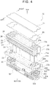
- each battery module 20 includes plural cylindrical batteries 21, a thermal diffusing plate 22, a resin cover 23, a ceiling cover 31, and a bottom cover 32.
- the thermal diffusing plate 22 holds the cylindrical batteries 21, and the resin cover 23 covers an outer circumference of a cylindrical battery set held by the thermal diffusing plate 22.
- the ceiling cover 31 is disposed onto an upper portion of the cover 23.
- the bottom cover 32 is disposed to a lower portion of the thermal diffusing plate 22, and is formed in a tray shape.
- the cylindrical batteries 21 are chargeable and dischargeable secondary batteries, such as nickel-metal hydride batteries and lithium-ion batteries housed in a cylindrical case, for example.
- the thermal diffusing plate 22 is a metallic plate, such as aluminum, provided with a number of through-holes 22a into which the cylindrical batteries 21 are inserted.
- the cylindrical batteries 21 are assembled to the thermal diffusing plate 22.
- the cylindrical batteries 21 are inserted into the through-holes 22a, and are then fixed to the through-holes 22a by filling a gap between inner surfaces (cylindrical surfaces) of the through-holes 22a and outer surfaces (cylindrical surfaces) of the cylindrical batteries 21 with an adhesive agent.
- the cylindrical batteries 21 are assembled into the through-holes 22a of the thermal diffusing plate 22, thereby transferring heat from the outer surfaces (cylindrical surfaces) of the cylindrical batteries 21 having a higher temperature to the thermal diffusing plate 22 by thermal conductivity so as to decrease the temperature of the cylindrical batteries 21 having a higher temperature. Furthermore, heat of the thermal diffusing plate 22 is transferred to the cylindrical batteries 21 having a lower temperature by thermal conductivity so as to increase the temperature of the cylindrical batteries 21 having a lower temperature. This means that the cylindrical batteries 21 are held by the through-holes 22a so that heat transfer can be achieved between the cylindrical surfaces thereof and the thermal diffusing plate 22.
- the thermal diffusing plate 22 suppresses variation in temperature among the cylindrical batteries 21.
- the thermal diffusing plate 22 is formed by a metallic material, such as aluminum, having a high thermal conductivity so as to promote heat transfer among the cylindrical batteries 21.
- the thermal diffusing plate 22 has a thickness sufficient for holding the cylindrical batteries 21 by the cylindrical surfaces of the through-holes 22a, and achieving an effective heat transfer by thermal conductivity, specifically, approximately 10 to 20 mm, or a 1/4 thickness of a length of each cylindrical battery 21, for example.
- the resin cover 23 includes a ceiling plate 23a and a rectangular cylinder 23b.
- the ceiling plate 23a is a member having holes 23c from which respective positive electrodes 21a of the cylindrical batteries 21 project.
- the rectangular cylinder 23b is configured to cover the outer circumference of the plural cylindrical batteries 21 that are assembled to the thermal diffusing plate 22. As shown in FIG. 4 , if the cover 23 is attached onto the thermal diffusing plate 22, the respective positive electrodes 21 a of the cylindrical batteries 21 project from corresponding holes 23c of the ceiling plate 23a of the cover 23. As shown in FIG. 4 and FIG.
- plural positive-electrode bus bars 29 are disposed onto the holes 23c of the cover 23 in such a manner that each of the positive-electrode bus bars 29 connects the positive electrodes 21a of the cylindrical batteries 21 for each of several groups.
- the resin ceiling cover 31 is disposed onto the plural positive-electrode bus bars 29.
- an L-shaped upper flange 24 and an L-shaped lower flange 25 are formed on a side surface of the cover 23 in a manner as to protrude outward.
- a flange surface of the upper flange 24 extends upward, and a flange surface of the lower flange 25 extends downward.
- FIG. 5 there are two types of battery modules 20: each battery module 20 of one type having the flanges 24, 25 formed on the left side surface of the cover 23, and each battery module 20 of the other type having the flanges 24, 25 formed on the right side surface of the cover 23.
- These battery modules 20 of two types are arranged in combination with each other side by side in a vehicle left-right direction. As shown in FIG.
- the battery modules 20 of two types are configured in such a manner that the flange surfaces of the flanges 24 of the respective battery modules 20 face each other, and the flange surfaces of the flanges 25 of the respective battery modules 20 face each other.
- the battery modules of two types are combined with a seal member 28, such as a rubber plate, held between the corresponding flange surfaces that face each other.
- the flange surfaces of the corresponding flanges 24 and the flange surfaces of the corresponding flanges 25 of the respective battery modules 20 are positioned in such a manner that upper surfaces 22b of the corresponding thermal diffusing plates 22 of the respective battery modules 20 are positioned in the identical plane, and lower surfaces 22c of the corresponding thermal diffusing plates 22 of the respective battery modules 20 are positioned in the identical plane. If the battery modules 20 are combined in the above manner, the air flow passage 26 is formed between the adjacent battery modules 20. As shown in FIG. 4 , slits 27 that introduce the cooling air for the cylindrical batteries 21 are formed in a longitudinal side surface of the cover 23 that forms the air flow passage 26. FIG.
- FIG. 4 illustrates the slits 27 formed in the left side surface of the cover 23, but the same slits 27 are formed in the right side surface thereof where no flanges 24, 25 of the cover 23 are formed.
- the slits 27 formed in the right side surface of the cover 23 face the air flow passage 26.
- the slits 27 are configured to exhaust the air after having flown into the cover 23 and having cooled the cylindrical batteries 21 from the cover 23.
- the upper surface 22b of the thermal diffusing plate 22, the cover 23, and the ceiling cover 31 define a space where the cylindrical batteries 21 are housed, and also forms a first chamber 40 that is a space into which the cooling air for cooling the cylindrical batteries 21 is introduced.
- a negative-electrode bus bar assembly 30 that connects the negative electrodes 21b of the cylindrical batteries 21 for each of several groups is disposed on the bottom side of the lower surface 22c of the thermal diffusing plate 22.
- the negative-electrode bus bar assembly 30 is configured by arranging and resin-molding plural negative-electrode bus bars 30a each of which is formed by forming holes 30c corresponding to the arrangement of the cylindrical batteries 21 in a plate having the same shape as that of the positive-electrode bus bar 29.
- a platy terminal 30b in contact with the negative electrode 21b of each cylindrical battery 21 is formed in the hole 30c of each negative-electrode bus bar 30a.
- Each positive-electrode bus bar 29 connects the positive electrodes 21a of the cylindrical batteries 21 in the same group, and each negative-electrode bus bar 30a connects the negative electrodes 21b of the cylindrical batteries 21 in the same group, and the cylindrical batteries 21 in each same group that are connected by each positive-electrode bus bar 29 and the cylindrical batteries 21 in each same group that are connected by each negative-electrode bus bar 30a are connected, respectively in parallel.
- the positive-electrode bus bars 29 and the negative-electrode bus bars 30a are connected by a connecting bus bar (not shown) so as to configure the battery set in which the plural groups each of which includes the plural cylindrical batteries 21 connected in parallel are connected in series.
- the bottom cover 32 of which center portion is recessed in a tray-shape, and of which bottom surface has reinforcing recessed-protruding portions 32a is disposed to a bottom side of the negative-electrode bus bar assembly 30.
- a resin rib 30d protrudes from an outer circumference of the bottom surface of the negative-electrode bus bar assembly 30, and the resin rib 30d is disposed such that an outer circumference of the bottom cover 32 comes into contact with a front end of the rib 30d.
- the bottom cover 32 is formed by metal having a high heat transfer property, such as aluminum.
- an opening 30e in a substantially rectangular shape is provided at each longitudinal end of the negative-electrode bus bar assembly 30.
- An opening 22e is provided at each longitudinal end of the lower surface 22c of the thermal diffusing plate 22.
- An opening 22d is provided in each longitudinal end surface of the thermal diffusing plate 22. The opening 22d in each end surface and the opening 22e of the lower surface 22c of the thermal diffusing plate 22 are configured to be communicated with each other through a flow passage bent in an L-shape.
- the opening 30e of the negative-electrode bus bar assembly 30 is overlaid with the opening 22e of the lower surface of the thermal diffusing plate 22. Accordingly, the negative-electrode bus bar assembly 30 and the bottom cover 32 are attached to the thermal diffusing plate 22, thereby forming a flow passage that communicates a space between the thermal diffusing plate 22 and the bottom cover 32 with the opening 22d in each end surface of the thermal diffusing plate 22.
- Each of the negative electrodes 21b of the cylindrical batteries 21 has a structure to open an end surface thereof by inner pressure if gas is generated inside the cylindrical battery 21 so as to exhaust the gas to the outside.
- the gas exhausted from the negative electrodes 21b of the cylindrical batteries 21 flows into the space formed under the thermal diffusing plate 22.
- the gas having flown into this space flows through between the thermal diffusing plate 22 and the bottom cover 32 to the both ends of the battery module 20, and is exhausted through the opening 30e of the negative-electrode bus bar assembly 30, each opening 22e and each opening 22d of the thermal diffusing plate 22 to the outside.
- the space between the thermal diffusing plate 22 and the bottom cover 32 configures a smoke exhaust passage 60 to exhaust the gas if the gas is discharged from the cylindrical batteries 21.
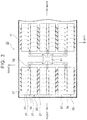
- the circumference of the space below the air flow passage 26 is surrounded in four directions by the side surfaces of the respective covers 23, the respective flanges 25, the right side surface and the left side surface of the respective thermal diffusing plates 22, the flat plates 33, and the flat plates attached to the both end surfaces in the vehicle front-rear direction of the adjacent battery modules 20; therefore, this space becomes a second chamber 50 as a closed space.
- a heater support member 34 that supports the bar heater 35 is disposed on the flat plate 33.
- the bar heater 35 is attached onto the heater support member 34.
- the second chamber 50 corresponds to respective outer spaces of the battery modules 20.
- the left side surface and the right side surface of the respective thermal diffusing plates 22 of the adjacent battery modules 20 serve as part of a wall that partitions the closed space.
- heat emitted from the bar heater 35 heats the air in the second chamber 50, and circulates the air in the second chamber 50 by convection.
- the air in the second chamber 50 moves as indicated by arrows 91 of FIG. 5 by convection.
- the heated air comes into contact with the side surfaces of the respective thermal diffusing plates 22 of the adjacent battery modules 20 so as to heat these surfaces.
- Each thermal diffusing plate 22 is made of metal having a high thermal conductivity, such as aluminum. Heat input into the left end surface and the right end surface of the corresponding thermal diffusing plates 22 transfers from the surface of each through-hole 22a of each thermal diffusing plate 22 to the cylindrical surface of each cylindrical battery 21 so as to heat the cylindrical surface of each cylindrical battery 21.
- the thermal diffusing plate 22 can efficiently promote heat transfer among the cylindrical batteries 21, thus efficiently heating each cylindrical battery 21. Because there is an air space between the bar heater 35 and the thermal diffusing plates 22, the side surface of each thermal diffusing plate 22 can be uniformly heated in the longitudinal direction by the bar heater 35. Accordingly, it is possible to heat each cylindrical battery 21 while preventing increase in temperature difference among the cylindrical batteries 21 of each battery module 20.
- the battery pack 10 of the present embodiment is configured in a manner as to form the closed space between the respective thermal diffusing plates 22 below the air flow passage 26.
- the bar heater 35 is disposed in this closed space, and each of the cylindrical batteries 21 of each battery module 20 is heated by this bar heater 35.
- each of the cylindrical batteries 21 of the two battery modules 20 can be heated by the single bar heater 35. Accordingly, it is possible to heat each of the cylindrical batteries 21 of the plural battery modules 20 housed in the battery pack 10 by a fewer number of heaters.
- the empty space between the two adjacent battery modules 20 is so closed as to form the closed space.
- the bar heater 35 is disposed in this closed space.
- the battery pack 10 it is unnecessary to provide a dedicated space for the bar heater 35, and thus the inner space of the battery pack 10 can be used as widely as possible. It is also possible to configure the battery pack 10 to be compact. Furthermore, it is possible to mount more cylindrical batteries 21 or more battery modules 20 in the battery pack 10 having the same capacity.
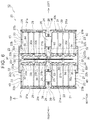
- FIG. 6 another embodiment of the present invention will be explained.
- the same reference numerals are used for components that are the same as those of the embodiment explained with reference to FIG. 1 to FIG. 5 , and description thereof will be omitted.
- four battery modules 20 are integrally combined. More specifically, one set of battery modules 20 configured by laterally combining the two battery modules 20 of FIG. 4 in a manner as to form the air flow passage 26 therebetween as shown in FIG. 5 is combined with another set of battery modules 20 having the same configuration. These two sets of battery modules 20 are combined with each other while the respective bottom covers 32 thereof face each other. Each bottom cover 32 defines the smoke exhaust passage 60 of each battery module 20. In this manner, the four battery modules 20 are integrally combined. As shown in FIG. 6 , resin plates 36 are disposed to side surfaces with no flow passage 26 of the respective battery modules 20. The same plate as the plate 36 shown in FIG.
- the second chamber 50 is a closed space surrounded by the plates 36, the bottom covers 32, the thermal diffusing plates 22, the covers 23, and the flange 25.
- a seat heater 37 is disposed between the facing bottom covers 32 in the second chamber 50, and air spaces are respectively formed between the seat heater 37 and the respective bottom covers 32.
- heat emitted from the seat heater 37 heats the air in the second chamber 50, and circulates the air in the second chamber by convection.
- the air in the second chamber 50 moves due to the convection as indicated by arrows 92 of FIG. 6 .
- the heated air comes into contact with the outer surfaces of the bottom covers 32 of the respective battery modules 20, and heats the respective surfaces thereof.
- Each bottom cover 32 is made of a metallic material or the like excellent in heat transfer property.
- the air in the smoke exhaust passages 60 is circulated by convection as indicated by arrows 94 of FIG. 6 by the respective bottom covers 32.
- This air convection heats the lower surfaces 22c of the respective thermal diffusing plates 22 and the negative electrodes 21b of the respective cylindrical batteries 21, thereby heating the cylindrical batteries 21 from the respective negative electrodes 21b.
- the air in the respective spaces between the side surfaces of the respective thermal diffusing plates 22 and the corresponding air flow passages 26 is also circulated by convection as indicated by arrows 93 of FIG. 6 so as to heat the side surfaces of the respective thermal diffusing plates 22.
- each thermal diffusing plate 22 is made of metal having a high thermal conductivity, such as aluminum, heat input into the left and right end surfaces of the respective thermal diffusing plates 22 is transferred from the surfaces of the through-holes 22a of each thermal diffusing plate 22 to the cylindrical surfaces of the respective cylindrical batteries 21 so as to heat the cylindrical surfaces of the cylindrical batteries 21.
- the air spaces are formed respectively between the seat heater 37 and the thermal diffusing plates 22, and between the seat heater 37 and the bottom covers 32. Since the side surface of each thermal diffusing plate 22 and each bottom cover 32 are heated through the air space by the seat heater 37, it is possible to heat each of the cylindrical batteries 21 while preventing increase in temperature difference among the cylindrical batteries 21 of each battery module 20.
- the four battery modules 20 are arranged in such a manner that the respective bottom covers 32 of the battery modules 20 face each other with the seat heater 37 disposed between the respective bottom covers 32.
- the single seat heater 37 it is possible to heat each of the cylindrical batteries 21 of the four battery modules 20 by the single seat heater 37.
- the empty space by the adjacent battery modules 20 is closed into a closed space.
- the seat heater 37 is disposed in this closed space.
- the battery pack 10 is installed under the floor of the electric vehicle 100.
- the present invention may be applicable to not only the battery pack 10 installed in this manner, but also to the battery pack 10 installed in a space behind the rear seat 106 as shown in FIG. 1 , or the battery pack 10 installed in a luggage space, for example.
- the present invention may also be applicable to other electric-motor vehicles that are driven by engines and motors, such as hybrid vehicles.
Landscapes
- Engineering & Computer Science (AREA)
- Chemical & Material Sciences (AREA)
- Chemical Kinetics & Catalysis (AREA)
- Electrochemistry (AREA)
- General Chemical & Material Sciences (AREA)
- Manufacturing & Machinery (AREA)
- Mechanical Engineering (AREA)
- Transportation (AREA)
- Sustainable Energy (AREA)
- Power Engineering (AREA)
- Sustainable Development (AREA)
- Life Sciences & Earth Sciences (AREA)
- Physics & Mathematics (AREA)
- Electromagnetism (AREA)
- Combustion & Propulsion (AREA)
- Secondary Cells (AREA)
- Battery Mounting, Suspending (AREA)
- Cooling, Air Intake And Gas Exhaust, And Fuel Tank Arrangements In Propulsion Units (AREA)
- Arrangement Or Mounting Of Propulsion Units For Vehicles (AREA)
Applications Claiming Priority (1)
| Application Number | Priority Date | Filing Date | Title |
|---|---|---|---|
| JP2015059252A JP6256397B2 (ja) | 2015-03-23 | 2015-03-23 | 電池パック |
Publications (2)
| Publication Number | Publication Date |
|---|---|
| EP3073546A1 true EP3073546A1 (fr) | 2016-09-28 |
| EP3073546B1 EP3073546B1 (fr) | 2020-03-04 |
Family
ID=55527404
Family Applications (1)
| Application Number | Title | Priority Date | Filing Date |
|---|---|---|---|
| EP16159859.4A Active EP3073546B1 (fr) | 2015-03-23 | 2016-03-11 | Bloc-batteries |
Country Status (5)
| Country | Link |
|---|---|
| US (1) | US10644365B2 (fr) |
| EP (1) | EP3073546B1 (fr) |
| JP (1) | JP6256397B2 (fr) |
| KR (1) | KR101800334B1 (fr) |
| CN (1) | CN105990625B (fr) |
Cited By (6)
| Publication number | Priority date | Publication date | Assignee | Title |
|---|---|---|---|---|
| WO2018071751A1 (fr) * | 2016-10-14 | 2018-04-19 | Inevit Llc | Zone de montage de module de batterie d'un système de stockage d'énergie |
| WO2019232556A1 (fr) * | 2018-06-08 | 2019-12-12 | Raiffeisenlandesbank Oberösterreich Aktiengesellschaft | Dispositif de régulation thermique pour des cellules e batterie individuelles assemblées en un module |
| GB2577261A (en) * | 2018-09-18 | 2020-03-25 | Mclaren Automotive Ltd | Battery |
| WO2020182612A1 (fr) * | 2019-03-13 | 2020-09-17 | Bayerische Motoren Werke Aktiengesellschaft | Dispositif de stockage d'énergie conçu pour un véhicule automobile, véhicule automobile et procédé de production |
| EP3878683A1 (fr) * | 2016-10-05 | 2021-09-15 | Voltu Motor, Inc. | Dispositif de stockage d'énergie refroidi par fluide et encapsulé dans une résine |
| EP3318443B1 (fr) * | 2016-11-02 | 2022-03-16 | Proterra Inc. | Système de batterie d'un véhicule électrique |
Families Citing this family (22)
| Publication number | Priority date | Publication date | Assignee | Title |
|---|---|---|---|---|
| JP6248972B2 (ja) | 2015-03-23 | 2017-12-20 | トヨタ自動車株式会社 | 電池パック |
| JP6256439B2 (ja) * | 2015-09-15 | 2018-01-10 | 株式会社デンソー | 電池パック |
| US9912023B1 (en) * | 2016-09-07 | 2018-03-06 | Thunder Power New Energy Vehicle Development Company Limited | Battery system housing with integrated cooling pipe |
| DE102016123553A1 (de) * | 2016-12-06 | 2018-06-07 | Dr. Ing. H.C. F. Porsche Aktiengesellschaft | Fahrzeugkarosserie für ein elektrisch angetriebenes Fahrzeug |
| KR101977454B1 (ko) * | 2017-01-04 | 2019-05-10 | 삼성에스디아이 주식회사 | 배터리 팩 |
| JP2018113219A (ja) * | 2017-01-13 | 2018-07-19 | トヨタ自動車株式会社 | 蓄電装置 |
| KR102172517B1 (ko) * | 2017-04-04 | 2020-10-30 | 주식회사 엘지화학 | 크래쉬 빔 구조를 갖는 배터리 팩 |
| JP6798432B2 (ja) * | 2017-06-20 | 2020-12-09 | トヨタ自動車株式会社 | 組電池、電池モジュール及び組電池の製造方法 |
| US11742511B2 (en) * | 2017-07-28 | 2023-08-29 | Panasonic Intellectual Property Management Co., Ltd. | Linked battery module and linked battery pack |
| KR102397774B1 (ko) | 2017-11-14 | 2022-05-13 | 주식회사 엘지에너지솔루션 | 배터리 모듈 및 이를 포함하는 배터리 팩 |
| JP6939492B2 (ja) * | 2017-12-11 | 2021-09-22 | トヨタ自動車株式会社 | 電池モジュール |
| KR102263763B1 (ko) | 2018-01-17 | 2021-06-09 | 주식회사 엘지에너지솔루션 | 방열 및 연쇄발화 방지 구조를 구비한 멀티 레이어 원통형 전지모듈 및 이를 포함하는 전지팩 |
| CN108172724A (zh) * | 2018-01-25 | 2018-06-15 | 湖南威威胜新能源技术有限公司 | 一种电池模组 |
| KR102353367B1 (ko) | 2018-09-28 | 2022-01-18 | 주식회사 엘지에너지솔루션 | 배터리 셀 조립체, 이러한 배터리 셀 조립체를 포함하는 배터리 모듈, 이러한 배터리 모듈을 포함하는 배터리 팩 및 이러한 배터리 팩을 포함하는 자동차 |
| JP7191290B2 (ja) * | 2018-12-26 | 2022-12-19 | マツダ株式会社 | バッテリ搭載装置 |
| CN111106277B (zh) * | 2018-12-29 | 2021-05-07 | 宁德时代新能源科技股份有限公司 | 电池包 |
| JP7047783B2 (ja) | 2019-01-14 | 2022-04-05 | トヨタ自動車株式会社 | 電池パック |
| DE102019116969A1 (de) * | 2019-06-24 | 2020-12-24 | Bayerische Motoren Werke Aktiengesellschaft | Energiespeichereinrichtung für ein Kraftfahrzeug, Kraftfahrzeug sowie Herstellungsverfahren |
| US11588199B2 (en) * | 2020-03-10 | 2023-02-21 | Karma Automotive Llc | Vehicle battery system |
| US11967724B2 (en) * | 2020-10-06 | 2024-04-23 | Rivian Ip Holdings, Llc | Battery module support beam |
| CN115295918B (zh) * | 2022-08-12 | 2023-09-05 | 广东宇华热能科技有限公司 | 一种新能源车热管理系统 |
| US20240063464A1 (en) * | 2022-08-16 | 2024-02-22 | Rivian Ip Holdings, Llc | Structural module thermal compoment |
Citations (8)
| Publication number | Priority date | Publication date | Assignee | Title |
|---|---|---|---|---|
| EP1333521A2 (fr) * | 2002-01-30 | 2003-08-06 | Sanyo Electric Co., Ltd. | Batterie avec capteurs de température |
| US20060068278A1 (en) * | 2003-01-04 | 2006-03-30 | Bloom Richard L | Vehicle battery pack insulator |
| EP1705743A1 (fr) * | 2005-03-25 | 2006-09-27 | Samsung SDI Co., Ltd. | Module de batteries |
| JP2008053149A (ja) | 2006-08-28 | 2008-03-06 | Panasonic Ev Energy Co Ltd | ヒータ付き組電池構造体 |
| WO2012124446A1 (fr) * | 2011-03-14 | 2012-09-20 | 株式会社 豊田自動織機 | Module de batterie |
| JP2012243535A (ja) | 2011-05-18 | 2012-12-10 | Sanyo Electric Co Ltd | 電池パック |
| US20130017422A1 (en) * | 2011-07-12 | 2013-01-17 | Bae Joon-Soo | Battery pack assembly |
| JP5392407B2 (ja) | 2011-04-28 | 2014-01-22 | トヨタ自動車株式会社 | 電池パック |
Family Cites Families (13)
| Publication number | Priority date | Publication date | Assignee | Title |
|---|---|---|---|---|
| JP2006278377A (ja) * | 2005-03-28 | 2006-10-12 | Shin Kobe Electric Mach Co Ltd | プリント配線板積み重ね用の間紙 |
| JP4902164B2 (ja) * | 2005-09-28 | 2012-03-21 | 三洋電機株式会社 | 電源装置 |
| KR100839374B1 (ko) * | 2007-04-27 | 2008-06-19 | 삼성에스디아이 주식회사 | 전지 모듈 |
| FR2924857B1 (fr) * | 2007-12-06 | 2014-06-06 | Valeo Equip Electr Moteur | Dispositif d'alimentation electrique comportant un bac de reception d'unites de stockage a ultra capacite |
| JP5136263B2 (ja) * | 2008-07-28 | 2013-02-06 | トヨタ自動車株式会社 | 蓄電装置 |
| US20120021260A1 (en) | 2010-01-29 | 2012-01-26 | Panasonic Corporation | Battery module |
| KR101265901B1 (ko) * | 2010-04-16 | 2013-05-20 | 도요타지도샤가부시키가이샤 | 축전 장치 |
| JP4923314B1 (ja) * | 2010-09-17 | 2012-04-25 | パナソニック株式会社 | 電池ブロック及び電池モジュール |
| US20150042284A1 (en) * | 2011-09-21 | 2015-02-12 | Toyota Jidosha Kabushiki Kaisha | Control apparatus for vehicle battery and control method for vehicle battery |
| JP5871067B2 (ja) * | 2012-07-13 | 2016-03-01 | 日産自動車株式会社 | 電池構造体 |
| JP5623483B2 (ja) * | 2012-09-18 | 2014-11-12 | トヨタ自動車株式会社 | 電池、電池パック、電池の製造方法 |
| US9634364B2 (en) * | 2014-10-28 | 2017-04-25 | Ford Global Technologies, Llc | Support structure for traction battery assembly with integrated thermal plate |
| JP6536497B2 (ja) * | 2016-06-30 | 2019-07-03 | トヨタ自動車株式会社 | 電池パック |
-
2015
- 2015-03-23 JP JP2015059252A patent/JP6256397B2/ja active Active
-
2016
- 2016-03-11 EP EP16159859.4A patent/EP3073546B1/fr active Active
- 2016-03-14 KR KR1020160030181A patent/KR101800334B1/ko active IP Right Grant
- 2016-03-18 US US15/074,565 patent/US10644365B2/en active Active
- 2016-03-21 CN CN201610161036.7A patent/CN105990625B/zh active Active
Patent Citations (8)
| Publication number | Priority date | Publication date | Assignee | Title |
|---|---|---|---|---|
| EP1333521A2 (fr) * | 2002-01-30 | 2003-08-06 | Sanyo Electric Co., Ltd. | Batterie avec capteurs de température |
| US20060068278A1 (en) * | 2003-01-04 | 2006-03-30 | Bloom Richard L | Vehicle battery pack insulator |
| EP1705743A1 (fr) * | 2005-03-25 | 2006-09-27 | Samsung SDI Co., Ltd. | Module de batteries |
| JP2008053149A (ja) | 2006-08-28 | 2008-03-06 | Panasonic Ev Energy Co Ltd | ヒータ付き組電池構造体 |
| WO2012124446A1 (fr) * | 2011-03-14 | 2012-09-20 | 株式会社 豊田自動織機 | Module de batterie |
| JP5392407B2 (ja) | 2011-04-28 | 2014-01-22 | トヨタ自動車株式会社 | 電池パック |
| JP2012243535A (ja) | 2011-05-18 | 2012-12-10 | Sanyo Electric Co Ltd | 電池パック |
| US20130017422A1 (en) * | 2011-07-12 | 2013-01-17 | Bae Joon-Soo | Battery pack assembly |
Cited By (11)
| Publication number | Priority date | Publication date | Assignee | Title |
|---|---|---|---|---|
| EP3878683A1 (fr) * | 2016-10-05 | 2021-09-15 | Voltu Motor, Inc. | Dispositif de stockage d'énergie refroidi par fluide et encapsulé dans une résine |
| AU2017338922B2 (en) * | 2016-10-05 | 2023-04-06 | Voltu Motor, Inc. | Electric vehicle |
| WO2018071751A1 (fr) * | 2016-10-14 | 2018-04-19 | Inevit Llc | Zone de montage de module de batterie d'un système de stockage d'énergie |
| CN110073513A (zh) * | 2016-10-14 | 2019-07-30 | 伊奈维特有限责任公司 | 能量存储系统的电池模块安装区域 |
| US10381618B2 (en) | 2016-10-14 | 2019-08-13 | Inevit Llc | Battery module mounting area of an energy storage system |
| EP3318443B1 (fr) * | 2016-11-02 | 2022-03-16 | Proterra Inc. | Système de batterie d'un véhicule électrique |
| WO2019232556A1 (fr) * | 2018-06-08 | 2019-12-12 | Raiffeisenlandesbank Oberösterreich Aktiengesellschaft | Dispositif de régulation thermique pour des cellules e batterie individuelles assemblées en un module |
| GB2577261A (en) * | 2018-09-18 | 2020-03-25 | Mclaren Automotive Ltd | Battery |
| GB2577261B (en) * | 2018-09-18 | 2022-05-25 | Mclaren Automotive Ltd | Battery |
| WO2020182612A1 (fr) * | 2019-03-13 | 2020-09-17 | Bayerische Motoren Werke Aktiengesellschaft | Dispositif de stockage d'énergie conçu pour un véhicule automobile, véhicule automobile et procédé de production |
| US11872876B2 (en) | 2019-03-13 | 2024-01-16 | Bayerische Motoren Werke Aktiengesellschaft | Energy storage device for a motor vehicle, motor vehicle, and production method |
Also Published As
| Publication number | Publication date |
|---|---|
| KR101800334B1 (ko) | 2017-11-22 |
| CN105990625B (zh) | 2019-04-23 |
| JP6256397B2 (ja) | 2018-01-10 |
| US20160285142A1 (en) | 2016-09-29 |
| KR20160113970A (ko) | 2016-10-04 |
| CN105990625A (zh) | 2016-10-05 |
| EP3073546B1 (fr) | 2020-03-04 |
| JP2016178066A (ja) | 2016-10-06 |
| US10644365B2 (en) | 2020-05-05 |
Similar Documents
| Publication | Publication Date | Title |
|---|---|---|
| EP3073546B1 (fr) | Bloc-batteries | |
| CA2924471C (fr) | Bloc-batterie | |
| US9306251B2 (en) | Battery pack | |
| JP6011949B2 (ja) | 車載用バッテリー | |
| US9614197B2 (en) | Onboard battery | |
| EP3984865A1 (fr) | Dessous de caisse de véhicule | |
| KR20190066731A (ko) | 셀 에지 직접 냉각 방식의 배터리 모듈 및 이를 포함하는 배터리 팩 | |
| JP2013001382A (ja) | 電気自動車のバッテリ冷却構造 | |
| WO2017047205A1 (fr) | Bloc-piles | |
| JP2008311016A (ja) | 電池パック | |
| EP4087021A1 (fr) | Bloc-batterie refroidi par air pour véhicule électrique | |
| JP5822281B2 (ja) | 電動車両用バッテリパック | |
| JP6344250B2 (ja) | 電動車両 | |
| JP6119529B2 (ja) | 電池システム | |
| JP2015149212A (ja) | 車載用バッテリー | |
| JP2018190517A (ja) | 車載用バッテリー | |
| JP6743576B2 (ja) | 電池パック構造 | |
| JP2016178048A (ja) | 電池パック | |
| US20230059324A1 (en) | Battery pack | |
| JP2016178050A (ja) | 電池パック |
Legal Events
| Date | Code | Title | Description |
|---|---|---|---|
| PUAI | Public reference made under article 153(3) epc to a published international application that has entered the european phase |
Free format text: ORIGINAL CODE: 0009012 |
|
| 17P | Request for examination filed |
Effective date: 20160311 |
|
| AK | Designated contracting states |
Kind code of ref document: A1 Designated state(s): AL AT BE BG CH CY CZ DE DK EE ES FI FR GB GR HR HU IE IS IT LI LT LU LV MC MK MT NL NO PL PT RO RS SE SI SK SM TR |
|
| AX | Request for extension of the european patent |
Extension state: BA ME |
|
| STAA | Information on the status of an ep patent application or granted ep patent |
Free format text: STATUS: EXAMINATION IS IN PROGRESS |
|
| 17Q | First examination report despatched |
Effective date: 20170920 |
|
| REG | Reference to a national code |
Ref country code: DE Ref legal event code: R079 Ref document number: 602016030896 Country of ref document: DE Free format text: PREVIOUS MAIN CLASS: H01M0002100000 Ipc: B60L0050500000 |
|
| GRAP | Despatch of communication of intention to grant a patent |
Free format text: ORIGINAL CODE: EPIDOSNIGR1 |
|
| STAA | Information on the status of an ep patent application or granted ep patent |
Free format text: STATUS: GRANT OF PATENT IS INTENDED |
|
| RIC1 | Information provided on ipc code assigned before grant |
Ipc: B60L 50/50 20190101AFI20190923BHEP |
|
| INTG | Intention to grant announced |
Effective date: 20191017 |
|
| GRAS | Grant fee paid |
Free format text: ORIGINAL CODE: EPIDOSNIGR3 |
|
| GRAA | (expected) grant |
Free format text: ORIGINAL CODE: 0009210 |
|
| STAA | Information on the status of an ep patent application or granted ep patent |
Free format text: STATUS: THE PATENT HAS BEEN GRANTED |
|
| AK | Designated contracting states |
Kind code of ref document: B1 Designated state(s): AL AT BE BG CH CY CZ DE DK EE ES FI FR GB GR HR HU IE IS IT LI LT LU LV MC MK MT NL NO PL PT RO RS SE SI SK SM TR |
|
| RAP1 | Party data changed (applicant data changed or rights of an application transferred) |
Owner name: TOYOTA JIDOSHA KABUSHIKI KAISHA |
|
| REG | Reference to a national code |
Ref country code: GB Ref legal event code: FG4D |
|
| REG | Reference to a national code |
Ref country code: CH Ref legal event code: EP |
|
| REG | Reference to a national code |
Ref country code: AT Ref legal event code: REF Ref document number: 1239983 Country of ref document: AT Kind code of ref document: T Effective date: 20200315 |
|
| REG | Reference to a national code |
Ref country code: DE Ref legal event code: R096 Ref document number: 602016030896 Country of ref document: DE |
|
| REG | Reference to a national code |
Ref country code: IE Ref legal event code: FG4D |
|
| PG25 | Lapsed in a contracting state [announced via postgrant information from national office to epo] |
Ref country code: FI Free format text: LAPSE BECAUSE OF FAILURE TO SUBMIT A TRANSLATION OF THE DESCRIPTION OR TO PAY THE FEE WITHIN THE PRESCRIBED TIME-LIMIT Effective date: 20200304 Ref country code: NO Free format text: LAPSE BECAUSE OF FAILURE TO SUBMIT A TRANSLATION OF THE DESCRIPTION OR TO PAY THE FEE WITHIN THE PRESCRIBED TIME-LIMIT Effective date: 20200604 Ref country code: RS Free format text: LAPSE BECAUSE OF FAILURE TO SUBMIT A TRANSLATION OF THE DESCRIPTION OR TO PAY THE FEE WITHIN THE PRESCRIBED TIME-LIMIT Effective date: 20200304 |
|
| REG | Reference to a national code |
Ref country code: NL Ref legal event code: MP Effective date: 20200304 |
|
| PG25 | Lapsed in a contracting state [announced via postgrant information from national office to epo] |
Ref country code: HR Free format text: LAPSE BECAUSE OF FAILURE TO SUBMIT A TRANSLATION OF THE DESCRIPTION OR TO PAY THE FEE WITHIN THE PRESCRIBED TIME-LIMIT Effective date: 20200304 Ref country code: SE Free format text: LAPSE BECAUSE OF FAILURE TO SUBMIT A TRANSLATION OF THE DESCRIPTION OR TO PAY THE FEE WITHIN THE PRESCRIBED TIME-LIMIT Effective date: 20200304 Ref country code: LV Free format text: LAPSE BECAUSE OF FAILURE TO SUBMIT A TRANSLATION OF THE DESCRIPTION OR TO PAY THE FEE WITHIN THE PRESCRIBED TIME-LIMIT Effective date: 20200304 Ref country code: GR Free format text: LAPSE BECAUSE OF FAILURE TO SUBMIT A TRANSLATION OF THE DESCRIPTION OR TO PAY THE FEE WITHIN THE PRESCRIBED TIME-LIMIT Effective date: 20200605 Ref country code: BG Free format text: LAPSE BECAUSE OF FAILURE TO SUBMIT A TRANSLATION OF THE DESCRIPTION OR TO PAY THE FEE WITHIN THE PRESCRIBED TIME-LIMIT Effective date: 20200604 |
|
| REG | Reference to a national code |
Ref country code: LT Ref legal event code: MG4D |
|
| PG25 | Lapsed in a contracting state [announced via postgrant information from national office to epo] |
Ref country code: NL Free format text: LAPSE BECAUSE OF FAILURE TO SUBMIT A TRANSLATION OF THE DESCRIPTION OR TO PAY THE FEE WITHIN THE PRESCRIBED TIME-LIMIT Effective date: 20200304 |
|
| PG25 | Lapsed in a contracting state [announced via postgrant information from national office to epo] |
Ref country code: PT Free format text: LAPSE BECAUSE OF FAILURE TO SUBMIT A TRANSLATION OF THE DESCRIPTION OR TO PAY THE FEE WITHIN THE PRESCRIBED TIME-LIMIT Effective date: 20200729 Ref country code: ES Free format text: LAPSE BECAUSE OF FAILURE TO SUBMIT A TRANSLATION OF THE DESCRIPTION OR TO PAY THE FEE WITHIN THE PRESCRIBED TIME-LIMIT Effective date: 20200304 Ref country code: RO Free format text: LAPSE BECAUSE OF FAILURE TO SUBMIT A TRANSLATION OF THE DESCRIPTION OR TO PAY THE FEE WITHIN THE PRESCRIBED TIME-LIMIT Effective date: 20200304 Ref country code: CZ Free format text: LAPSE BECAUSE OF FAILURE TO SUBMIT A TRANSLATION OF THE DESCRIPTION OR TO PAY THE FEE WITHIN THE PRESCRIBED TIME-LIMIT Effective date: 20200304 Ref country code: LT Free format text: LAPSE BECAUSE OF FAILURE TO SUBMIT A TRANSLATION OF THE DESCRIPTION OR TO PAY THE FEE WITHIN THE PRESCRIBED TIME-LIMIT Effective date: 20200304 Ref country code: SM Free format text: LAPSE BECAUSE OF FAILURE TO SUBMIT A TRANSLATION OF THE DESCRIPTION OR TO PAY THE FEE WITHIN THE PRESCRIBED TIME-LIMIT Effective date: 20200304 Ref country code: EE Free format text: LAPSE BECAUSE OF FAILURE TO SUBMIT A TRANSLATION OF THE DESCRIPTION OR TO PAY THE FEE WITHIN THE PRESCRIBED TIME-LIMIT Effective date: 20200304 Ref country code: SK Free format text: LAPSE BECAUSE OF FAILURE TO SUBMIT A TRANSLATION OF THE DESCRIPTION OR TO PAY THE FEE WITHIN THE PRESCRIBED TIME-LIMIT Effective date: 20200304 Ref country code: IS Free format text: LAPSE BECAUSE OF FAILURE TO SUBMIT A TRANSLATION OF THE DESCRIPTION OR TO PAY THE FEE WITHIN THE PRESCRIBED TIME-LIMIT Effective date: 20200704 |
|
| REG | Reference to a national code |
Ref country code: CH Ref legal event code: PL |
|
| REG | Reference to a national code |
Ref country code: AT Ref legal event code: MK05 Ref document number: 1239983 Country of ref document: AT Kind code of ref document: T Effective date: 20200304 |
|
| REG | Reference to a national code |
Ref country code: DE Ref legal event code: R097 Ref document number: 602016030896 Country of ref document: DE |
|
| REG | Reference to a national code |
Ref country code: BE Ref legal event code: MM Effective date: 20200331 |
|
| PG25 | Lapsed in a contracting state [announced via postgrant information from national office to epo] |
Ref country code: MC Free format text: LAPSE BECAUSE OF FAILURE TO SUBMIT A TRANSLATION OF THE DESCRIPTION OR TO PAY THE FEE WITHIN THE PRESCRIBED TIME-LIMIT Effective date: 20200304 Ref country code: LU Free format text: LAPSE BECAUSE OF NON-PAYMENT OF DUE FEES Effective date: 20200311 |
|
| PLBE | No opposition filed within time limit |
Free format text: ORIGINAL CODE: 0009261 |
|
| STAA | Information on the status of an ep patent application or granted ep patent |
Free format text: STATUS: NO OPPOSITION FILED WITHIN TIME LIMIT |
|
| PG25 | Lapsed in a contracting state [announced via postgrant information from national office to epo] |
Ref country code: LI Free format text: LAPSE BECAUSE OF NON-PAYMENT OF DUE FEES Effective date: 20200331 Ref country code: DK Free format text: LAPSE BECAUSE OF FAILURE TO SUBMIT A TRANSLATION OF THE DESCRIPTION OR TO PAY THE FEE WITHIN THE PRESCRIBED TIME-LIMIT Effective date: 20200304 Ref country code: IE Free format text: LAPSE BECAUSE OF NON-PAYMENT OF DUE FEES Effective date: 20200311 Ref country code: AT Free format text: LAPSE BECAUSE OF FAILURE TO SUBMIT A TRANSLATION OF THE DESCRIPTION OR TO PAY THE FEE WITHIN THE PRESCRIBED TIME-LIMIT Effective date: 20200304 Ref country code: CH Free format text: LAPSE BECAUSE OF NON-PAYMENT OF DUE FEES Effective date: 20200331 Ref country code: IT Free format text: LAPSE BECAUSE OF FAILURE TO SUBMIT A TRANSLATION OF THE DESCRIPTION OR TO PAY THE FEE WITHIN THE PRESCRIBED TIME-LIMIT Effective date: 20200304 |
|
| 26N | No opposition filed |
Effective date: 20201207 |
|
| PG25 | Lapsed in a contracting state [announced via postgrant information from national office to epo] |
Ref country code: BE Free format text: LAPSE BECAUSE OF NON-PAYMENT OF DUE FEES Effective date: 20200331 Ref country code: SI Free format text: LAPSE BECAUSE OF FAILURE TO SUBMIT A TRANSLATION OF THE DESCRIPTION OR TO PAY THE FEE WITHIN THE PRESCRIBED TIME-LIMIT Effective date: 20200304 Ref country code: PL Free format text: LAPSE BECAUSE OF FAILURE TO SUBMIT A TRANSLATION OF THE DESCRIPTION OR TO PAY THE FEE WITHIN THE PRESCRIBED TIME-LIMIT Effective date: 20200304 |
|
| GBPC | Gb: european patent ceased through non-payment of renewal fee |
Effective date: 20200604 |
|
| PG25 | Lapsed in a contracting state [announced via postgrant information from national office to epo] |
Ref country code: GB Free format text: LAPSE BECAUSE OF NON-PAYMENT OF DUE FEES Effective date: 20200604 Ref country code: FR Free format text: LAPSE BECAUSE OF NON-PAYMENT OF DUE FEES Effective date: 20200504 |
|
| REG | Reference to a national code |
Ref country code: DE Ref legal event code: R084 Ref document number: 602016030896 Country of ref document: DE |
|
| PG25 | Lapsed in a contracting state [announced via postgrant information from national office to epo] |
Ref country code: TR Free format text: LAPSE BECAUSE OF FAILURE TO SUBMIT A TRANSLATION OF THE DESCRIPTION OR TO PAY THE FEE WITHIN THE PRESCRIBED TIME-LIMIT Effective date: 20200304 Ref country code: MT Free format text: LAPSE BECAUSE OF FAILURE TO SUBMIT A TRANSLATION OF THE DESCRIPTION OR TO PAY THE FEE WITHIN THE PRESCRIBED TIME-LIMIT Effective date: 20200304 Ref country code: CY Free format text: LAPSE BECAUSE OF FAILURE TO SUBMIT A TRANSLATION OF THE DESCRIPTION OR TO PAY THE FEE WITHIN THE PRESCRIBED TIME-LIMIT Effective date: 20200304 |
|
| PG25 | Lapsed in a contracting state [announced via postgrant information from national office to epo] |
Ref country code: MK Free format text: LAPSE BECAUSE OF FAILURE TO SUBMIT A TRANSLATION OF THE DESCRIPTION OR TO PAY THE FEE WITHIN THE PRESCRIBED TIME-LIMIT Effective date: 20200304 Ref country code: AL Free format text: LAPSE BECAUSE OF FAILURE TO SUBMIT A TRANSLATION OF THE DESCRIPTION OR TO PAY THE FEE WITHIN THE PRESCRIBED TIME-LIMIT Effective date: 20200304 |
|
| P01 | Opt-out of the competence of the unified patent court (upc) registered |
Effective date: 20230427 |
|
| PGFP | Annual fee paid to national office [announced via postgrant information from national office to epo] |
Ref country code: DE Payment date: 20240130 Year of fee payment: 9 |