EP3072718A1 - Airflow direction adjustment device - Google Patents
Airflow direction adjustment device Download PDFInfo
- Publication number
- EP3072718A1 EP3072718A1 EP14863555.0A EP14863555A EP3072718A1 EP 3072718 A1 EP3072718 A1 EP 3072718A1 EP 14863555 A EP14863555 A EP 14863555A EP 3072718 A1 EP3072718 A1 EP 3072718A1
- Authority
- EP
- European Patent Office
- Prior art keywords
- housing
- airflow
- gear
- adjustment device
- direction adjustment
- Prior art date
- Legal status (The legal status is an assumption and is not a legal conclusion. Google has not performed a legal analysis and makes no representation as to the accuracy of the status listed.)
- Granted
Links
- 238000009434 installation Methods 0.000 claims description 3
- 238000005192 partition Methods 0.000 description 23
- 210000000078 claw Anatomy 0.000 description 8
- NJPPVKZQTLUDBO-UHFFFAOYSA-N novaluron Chemical compound C1=C(Cl)C(OC(F)(F)C(OC(F)(F)F)F)=CC=C1NC(=O)NC(=O)C1=C(F)C=CC=C1F NJPPVKZQTLUDBO-UHFFFAOYSA-N 0.000 description 5
- 239000000463 material Substances 0.000 description 2
- 230000000149 penetrating effect Effects 0.000 description 2
- 239000011347 resin Substances 0.000 description 2
- 229920005989 resin Polymers 0.000 description 2
- 230000000717 retained effect Effects 0.000 description 2
- 238000004378 air conditioning Methods 0.000 description 1
- 238000001816 cooling Methods 0.000 description 1
- 238000010586 diagram Methods 0.000 description 1
- 230000000694 effects Effects 0.000 description 1
- 238000005516 engineering process Methods 0.000 description 1
- 238000010438 heat treatment Methods 0.000 description 1
- 238000000034 method Methods 0.000 description 1
Images


Classifications
-
- F—MECHANICAL ENGINEERING; LIGHTING; HEATING; WEAPONS; BLASTING
- F24—HEATING; RANGES; VENTILATING
- F24F—AIR-CONDITIONING; AIR-HUMIDIFICATION; VENTILATION; USE OF AIR CURRENTS FOR SCREENING
- F24F13/00—Details common to, or for air-conditioning, air-humidification, ventilation or use of air currents for screening
- F24F13/02—Ducting arrangements
- F24F13/06—Outlets for directing or distributing air into rooms or spaces, e.g. ceiling air diffuser
-
- B—PERFORMING OPERATIONS; TRANSPORTING
- B60—VEHICLES IN GENERAL
- B60H—ARRANGEMENTS OF HEATING, COOLING, VENTILATING OR OTHER AIR-TREATING DEVICES SPECIALLY ADAPTED FOR PASSENGER OR GOODS SPACES OF VEHICLES
- B60H1/00—Heating, cooling or ventilating [HVAC] devices
- B60H1/34—Nozzles; Air-diffusers
- B60H1/3414—Nozzles; Air-diffusers with means for adjusting the air stream direction
- B60H1/3421—Nozzles; Air-diffusers with means for adjusting the air stream direction using only pivoting shutters
-
- B—PERFORMING OPERATIONS; TRANSPORTING
- B60—VEHICLES IN GENERAL
- B60H—ARRANGEMENTS OF HEATING, COOLING, VENTILATING OR OTHER AIR-TREATING DEVICES SPECIALLY ADAPTED FOR PASSENGER OR GOODS SPACES OF VEHICLES
- B60H1/00—Heating, cooling or ventilating [HVAC] devices
- B60H1/34—Nozzles; Air-diffusers
- B60H1/3414—Nozzles; Air-diffusers with means for adjusting the air stream direction
- B60H1/3435—Nozzles; Air-diffusers with means for adjusting the air stream direction using only a pivoting frame
- B60H1/3442—Nozzles; Air-diffusers with means for adjusting the air stream direction using only a pivoting frame the frame being spherical
-
- B—PERFORMING OPERATIONS; TRANSPORTING
- B64—AIRCRAFT; AVIATION; COSMONAUTICS
- B64D—EQUIPMENT FOR FITTING IN OR TO AIRCRAFT; FLIGHT SUITS; PARACHUTES; ARRANGEMENTS OR MOUNTING OF POWER PLANTS OR PROPULSION TRANSMISSIONS IN AIRCRAFT
- B64D13/00—Arrangements or adaptations of air-treatment apparatus for aircraft crew or passengers, or freight space, or structural parts of the aircraft
-
- F—MECHANICAL ENGINEERING; LIGHTING; HEATING; WEAPONS; BLASTING
- F24—HEATING; RANGES; VENTILATING
- F24F—AIR-CONDITIONING; AIR-HUMIDIFICATION; VENTILATION; USE OF AIR CURRENTS FOR SCREENING
- F24F13/00—Details common to, or for air-conditioning, air-humidification, ventilation or use of air currents for screening
- F24F13/02—Ducting arrangements
- F24F13/06—Outlets for directing or distributing air into rooms or spaces, e.g. ceiling air diffuser
- F24F13/065—Outlets for directing or distributing air into rooms or spaces, e.g. ceiling air diffuser formed as cylindrical or spherical bodies which are rotatable
-
- B—PERFORMING OPERATIONS; TRANSPORTING
- B60—VEHICLES IN GENERAL
- B60H—ARRANGEMENTS OF HEATING, COOLING, VENTILATING OR OTHER AIR-TREATING DEVICES SPECIALLY ADAPTED FOR PASSENGER OR GOODS SPACES OF VEHICLES
- B60H1/00—Heating, cooling or ventilating [HVAC] devices
- B60H1/34—Nozzles; Air-diffusers
- B60H2001/3471—Details of actuators
- B60H2001/3478—Details of actuators acting on additional damper doors
-
- B—PERFORMING OPERATIONS; TRANSPORTING
- B64—AIRCRAFT; AVIATION; COSMONAUTICS
- B64D—EQUIPMENT FOR FITTING IN OR TO AIRCRAFT; FLIGHT SUITS; PARACHUTES; ARRANGEMENTS OR MOUNTING OF POWER PLANTS OR PROPULSION TRANSMISSIONS IN AIRCRAFT
- B64D13/00—Arrangements or adaptations of air-treatment apparatus for aircraft crew or passengers, or freight space, or structural parts of the aircraft
- B64D2013/003—Cabin ventilation nozzles
-
- Y—GENERAL TAGGING OF NEW TECHNOLOGICAL DEVELOPMENTS; GENERAL TAGGING OF CROSS-SECTIONAL TECHNOLOGIES SPANNING OVER SEVERAL SECTIONS OF THE IPC; TECHNICAL SUBJECTS COVERED BY FORMER USPC CROSS-REFERENCE ART COLLECTIONS [XRACs] AND DIGESTS
- Y02—TECHNOLOGIES OR APPLICATIONS FOR MITIGATION OR ADAPTATION AGAINST CLIMATE CHANGE
- Y02T—CLIMATE CHANGE MITIGATION TECHNOLOGIES RELATED TO TRANSPORTATION
- Y02T50/00—Aeronautics or air transport
- Y02T50/40—Weight reduction
Definitions
- the present invention relates to an airflow-direction adjustment device varying a flow of air toward an air outlet side through a fin in a cooling and heating equipment, air conditioning equipment, or the like, and especially varying the fin through a gear mechanism.
- an air outlet is formed in, for example, an instrument panel of an automobile, and as shown in Patent Document 1 or 2 as an example, the airflow-direction adjustment device is a type comprising a housing in which a front end side is formed as an air outlet and a back end side is formed as an air inlet; the fin turnably supported inside the housing; and the gear mechanism for adjusting a direction of the fin by a rotation of an operating portion.
- the airflow-direction adjustment device of the Patent Document 1 comprises a case member which is the housing; a pair of airflow-direction-adjustment vane groups provided inside the case member; an operating portion provided on a front lower side of the case member; and a gear mechanism synchronizing each airflow-direction-adjustment vane group to vary.
- each airflow-direction-adjustment vane group includes two pedestals turnably supported as a supporting point of a turning shaft in a vertical direction; a plurality of vanes erected on an upper face of each pedestal; and gear portions provided around each pedestal as the gear mechanism, and engaged with each other. Then, when the operating portion is rotated, each pedestal rotates in a right-and-left direction through the gear portion as the supporting point of the turning shaft to vary a direction of each vane.
- the airflow-direction adjustment device of the Patent Document 2 comprises a housing opening front and back; seven fins obliquely disposed inside the housing; an operating portion provided at a front center of the housing; and a gear mechanism synchronizing each fin to vary.
- the gear mechanism includes a first gear portion integrally rotated with a rotation of the operating portion; a second gear portion engaged with the first gear portion; a third gear portion engaging the second gear portion, and integrated into the fin; and a ring-shaped gear with which the third gear portion is engaged. Then, when the operating portion is rotated, the direction of each fin varies through the first to third gear portions and the ring-shaped gear.
- the air is blown out through the air outlet in a direction according to an angle of a number of vanes or fins, or as a swirl flow so as to reasonably obtain a mild airflow blow.
- the number of vanes has to be at least four or more, and a shape becomes complicated and bulky.
- the number of fins increases further, and the gear mechanism synchronizing the operating portion to each fin becomes complicated as well. As a result, structurally, it is difficult to reduce the weight, and the number of parts increases or an assembly property deteriorates, thereby increasing a cost.
- An object of the present invention is to solve the aforementioned problems, and easily obtain a simplified structure and reduction in weight as well as excellence in the airflow-direction adjustment.
- Other objects of the present invention will be clarified in the following explanation of contents.
- the present invention provides an airflow-direction adjustment device comprising a housing in which a front end side is set as an air outlet and a back end side is set as an air inlet; a fin turnably supported inside the housing; and a gear mechanism for adjusting a direction of the fin by a rotation of an operating portion, and the aforementioned fin is formed by a pair of vanes disposed on right and left or top and bottom inside the housing, and each vane is turnably supported in a front-and-back direction of the housing respectively as a supporting point on a common pivot line N set in a plate width direction.
- the housing is formed by a cylinder shape in which the fin can be disposed, and wherein a front end side which is a just-in-front side is set as the air outlet, and an opposite back end side is set as the air inlet side.
- a frame member shown in an embodiment may be omitted, and there may be added an attachment portion and the like.
- the "fin” is formed by the pair of vanes disposed inside the housing.
- the pair of vanes is not limited to the same shape as in the embodiment, and includes an aspect having a different shape.
- the pair of vanes may be an embodiment wherein the housing of the embodiment is rotated approximately by 90 degrees, i.e. an aspect disposed on the top and bottom inside the housing in addition to an aspect disposed on the right and left inside the housing as in the embodiment.
- the fin is formed by the pair of vanes so as to be simplified as a vane structure, and the gear mechanism allowing the fin to turn in synchronization with the pair of vanes is simplified as well.
- the pair of vanes is disposed on the right and left or top and bottom inside the housing, and is turned as the supporting point on the common pivot line set in the plate width direction, so that, for example, even if a large impact is applied, a possibility that both vanes interfere with each other can be easily eliminated.
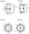
- Fig. 1 and Fig. 2 are schematic views; and Fig. 3(a) to Fig. 5(d) show an operating state of the airflow-direction adjustment device, and Figs. 3(b) , 4(b) , and 5(b) are diagrams showing cross-sectional states taken along a line A-A, a line A1-A1, and a line A2-A2.
- an airflow-direction adjustment device 1 of the embodiments comprises a housing 1 opening front and back ends; a pair of vanes 3A and 3B (3) forming fins turnably supported inside the housing 2; a gear mechanism 4 allowing an angle or a direction of each vane 3A and 3B to be adjusted; a nob 5 which is an operating portion operating the gear mechanism 4; and the like.
- the housing 2 is incorporated inside frame members, i.e. an outer frame 8 and a front frame 9 in an assembly state wherein each vane 2 and 3, the gear mechanism 4, the nob 5, and the like are incorporated.
- the outer frame 8 and the front frame 9 can be omitted by forming an attachment portion and the like in the housing 2.
- the housing 1, the vanes 2A and 2B, the gear mechanism 3, the nob 4, the outer frame 8, and the front frame 9 are resin articles; however, those may be made of materials other than a resin.
- the housing 2 has an approximately spherical shape, and an inside is formed in a shape close to a spherical shape wherein the pair of vanes 3A and 3B can turn around a supporting point on a common pivot line N.
- a front end side is set as an air outlet 2a
- a back end side is set as an air inlet 2b.
- the front end side includes cross-shaped arm portions 20a and 20b; a pivotal support portion 21 provided at a center thereof as a through hole; and a ring portion 20c provided on a concentric circle with the pivotal support portion 21, and connected to the arm portions 20a and 20b.
- the air outlet 2a is formed between the arm portions 20a and 20b, and the ring portion 20c.
- a convex portion 22 On an outer circumference, there is provided a convex portion 22 at an approximately intermediate portion of front and back. At the back end side, there are provided a pair of shaft holes 23 penetrating on the pivot line N; a pair of engagement holes 24a penetrating in a direction intersecting the pivot line N; and positioning portions 24 for a partition plate wherein an inner face of each engagement hole 24a is lowered by one step.
- each shaft hole 23 there are fitted shaft portions 32 of the later-described vanes 3A and 3B.
- a partition plate 25 shown with imaginary lines in Fig. 8(c) is positioned to be disposed in each positioning portion 24.
- the partition plate 25 is a partition dividing a back inner side of the housing 2 into two.
- the partition plate 25 has a semi-disk shape which is one size larger than that of the vanes 3A and 3B, and upper and lower portions where a curved portion and a straight portion intersect are horizontally cut (see Fig. 2 ), and there are included claws 26 provided in each cut face thereof.
- the partition plate 25 includes a concave-shaped pivotal support portion 29 provided in a middle of top and bottom or right and left of (an end face of) the straight portion; and cavities 28 respectively provided on both side faces, and wherein a portion close to the pivotal support portion 29 is lowered by one step, and which is rimed with a semicircular rib 27.
- each claw 26 is engaged with the engagement hole 24a to be mounted inside the housing 2.
- the inside of the housing 2 is divided into two to right and left or top and bottom by the partition plate 25 up to a vicinity of the pivot line N from a back side of the housing 2.
- the air in a state without the vanes 3A and 3B, the air is sucked into the housing from two portions divided as the inlet 2b of the housing 2, and flows in a direction of the outlet 2a, or in a state including the vanes 3A and 3B, the air becomes two flows on one side and four flows on both sides according to the angle of each vane 3A and 3B through the inlet 2b at the two portions divided as shown in Fig. 5(b) to flow in a direction of the outlet 2a in a state close to a swirl flow.
- the vanes 3A and 3B have an approximately semi-disk shape, and include the shaft portions 32 for a pivot projected at a middle of curved portions 31 of the vanes; and gear portions 6 integrally formed in a middle of straight portions 30 of the vanes.
- the shaft portion 32 and the gear portion 6 are provided on the aforementioned pivot line N.
- the shaft portion 32 of each vane is fitted into the corresponding shaft hole 23 of the housing 2, and the gear portion 6 of each vane engages one portion of a gear 7 provided on a back end side of a shaft 4 respectively.
- each vane 3A and 3B is disposed on right and left or top and bottom by sandwiching the partition plate 25 inside the housing 2, and supported turnably in a front-and-back direction as the supporting point of the common pivot line N (the shaft portion 32 and the gear portion 6 provided on the pivot line).
- the shaft 4 includes a flange portion 4a provided slightly just in front of a front end; a pair of claws 4b provided around the shaft just in front of the flange portion 4a; the gear 7 integrally formed at the back end side, and engaging each gear portion 6; and a protrusion 4c projected on an outer end face of the gear 7.
- the claws 4b engage a locking hole portion 5b connected to a hole portion 5a when the claws 4b are inserted into the hole portion 5a of the nob 5.
- the gear 7 and the gear portion 6 only have to have a relationship of transmitting a rotational movement between intersecting two shafts.
- the gear 7 and the gear portion 6 are formed by a bevel gear such as a timer gear, a spiral bevel gear, an oblique gear, and the like.
- the outer frame 8 is a main member portion of the frame member, and the inside has a shape into which the housing 2 can fit.
- the outer frame 8 is formed by a large-diameter cylinder portion 10 on a front side; a small-diameter cylinder portion 11 on a back side; and a curved-face cylinder portion 12 in a middle therebetween.
- the large-diameter cylinder portion 10 and the curved-face cylinder portion 12 there is provided a straight guide groove 13 guiding the convex portion 22 of the housing 2.
- protrusions 14 at four portions at equal intervals on the circumference of the large-diameter cylinder portion 10.
- the front frame 9 is formed by an approximately ring shape connected to the outer frame 8.
- the front frame 9 there are provided four engagement holes 15 corresponding to the protrusions 14; two attachment pieces 16 protruding between the engagement holes 15; an inner flange portion 17 forming a circular gap 18 between the inner flange portion 17 and an outer circumference; and a positioning small protrusion 19 protruding inside the gap 18, and engaging the guide groove 13 of the outer frame.
- the reference sign 17a is a die-cutting notch corresponding to the small protrusion 19.
- the flange portion 4a comes to a state wherein the flange portion 4a fits into the concave portion 20d.
- the nob 5 is mounted on the front end side of the shaft 4 protruding to an outside of the pivotal support portion 21.
- the pair of claws 4b engages the locking hole portion 5b connected to the hole portion 5a.
- the nob 5 is mounted on the shaft 4.
- the shaft 4 is turnably supported by the pivotal support portion 21 in a state wherein a front side is retained through the flange portion 4a and the nob 5.
- the partition plate 25 is assembled to the housing 2.
- upper and lower cut portions fit into the positioning portions 24 relative to the back inner side of the housing 2, and each claw 26 is engaged with the engagement hole 24a, so that the partition plate 25 is mounted on the housing 2.
- the protrusion 4c on a back end face fits into the pivotal support portion 29 of the partition plate 25, so that the shaft 4 is turnably supported in the fitting state of a back side.
- each vane 3A and 3B are turnably assembled to the housing 2.
- the shaft portion 32 fits into the corresponding shaft hole 23 on a housing side, and the gear portion 6 is engaged with the gear 7.
- the gear portion 6 is engaged with the gear 7.
- the gear portion 6 in a state wherein one portion is engaged with the gear 7, the remaining portions enter into the cavity 28 of the partition plate 25 to be released.
- each vane 3A and 3B can turn in the front-and-back direction of the housing as the supporting point of the shaft portion 32 and the gear portion 6 disposed on the aforementioned pivot line N.
- an assembly member itself wherein the shaft 4, the nob 5, the partition plate 25, and the vanes 3A and 3B are assembled relative to the housing 2 can be used as the airflow-direction adjustment device 1; however, in the example, the assembly member thereof is used as the airflow-direction adjustment device 1 in an aspect wherein the assembly member thereof is disposed inside the outer frame 8 and the front frame 9 which are the frame members. In that case, in the aforementioned assembly member, as shown in Fig. 1 , and Figs.
- the details can be modified or developed with reference to the aforementioned explanation provided that they comprise a structure specified in the first aspect.
- a turning groove may be provided in a circumferential direction of the frame members or the outer frame from the guide groove 13 so as to turn to the right and left along the turning groove only by a predetermined angle to carry out the airflow-direction adjustment further multilaterally.
Abstract


Description
- The present invention relates to an airflow-direction adjustment device varying a flow of air toward an air outlet side through a fin in a cooling and heating equipment, air conditioning equipment, or the like, and especially varying the fin through a gear mechanism.
- In the airflow-direction adjustment device of the subject of the present invention, an air outlet is formed in, for example, an instrument panel of an automobile, and as shown in
Patent Document - The airflow-direction adjustment device of the
Patent Document 1 comprises a case member which is the housing; a pair of airflow-direction-adjustment vane groups provided inside the case member; an operating portion provided on a front lower side of the case member; and a gear mechanism synchronizing each airflow-direction-adjustment vane group to vary. Also, each airflow-direction-adjustment vane group includes two pedestals turnably supported as a supporting point of a turning shaft in a vertical direction; a plurality of vanes erected on an upper face of each pedestal; and gear portions provided around each pedestal as the gear mechanism, and engaged with each other. Then, when the operating portion is rotated, each pedestal rotates in a right-and-left direction through the gear portion as the supporting point of the turning shaft to vary a direction of each vane. - The airflow-direction adjustment device of the
Patent Document 2 comprises a housing opening front and back; seven fins obliquely disposed inside the housing; an operating portion provided at a front center of the housing; and a gear mechanism synchronizing each fin to vary. Also, the gear mechanism includes a first gear portion integrally rotated with a rotation of the operating portion; a second gear portion engaged with the first gear portion; a third gear portion engaging the second gear portion, and integrated into the fin; and a ring-shaped gear with which the third gear portion is engaged. Then, when the operating portion is rotated, the direction of each fin varies through the first to third gear portions and the ring-shaped gear. -
- Patent Document 1: Japanese Unexamined Patent Application Publication No.
H08-197940 - Patent Document 2: German Patent Invention No.
102009041532 Specification (DE102009041532B4 ) - In structures of the
aforementioned Patent Documents Patent Document 1, as shown inFig. 1 andFig. 6 of thePatent Document 1 as an example, in order to effectively carry out an airflow-direction adjustment, the number of vanes has to be at least four or more, and a shape becomes complicated and bulky. In a case of thePatent Document 2, the number of fins increases further, and the gear mechanism synchronizing the operating portion to each fin becomes complicated as well. As a result, structurally, it is difficult to reduce the weight, and the number of parts increases or an assembly property deteriorates, thereby increasing a cost. - An object of the present invention is to solve the aforementioned problems, and easily obtain a simplified structure and reduction in weight as well as excellence in the airflow-direction adjustment. Other objects of the present invention will be clarified in the following explanation of contents.
- In order to obtain the aforementioned objects, the present invention provides an airflow-direction adjustment device comprising a housing in which a front end side is set as an air outlet and a back end side is set as an air inlet; a fin turnably supported inside the housing; and a gear mechanism for adjusting a direction of the fin by a rotation of an operating portion, and the aforementioned fin is formed by a pair of vanes disposed on right and left or top and bottom inside the housing, and each vane is turnably supported in a front-and-back direction of the housing respectively as a supporting point on a common pivot line N set in a plate width direction.
- Here, as for the "housing", for example, the housing is formed by a cylinder shape in which the fin can be disposed, and wherein a front end side which is a just-in-front side is set as the air outlet, and an opposite back end side is set as the air inlet side. In the housing, a frame member shown in an embodiment may be omitted, and there may be added an attachment portion and the like. The "fin" is formed by the pair of vanes disposed inside the housing. The pair of vanes is not limited to the same shape as in the embodiment, and includes an aspect having a different shape. Also, the pair of vanes may be an embodiment wherein the housing of the embodiment is rotated approximately by 90 degrees, i.e. an aspect disposed on the top and bottom inside the housing in addition to an aspect disposed on the right and left inside the housing as in the embodiment.
- In the aforementioned present invention, it is more preferable to be embodied as specified in the following.
- (1) A structure includes such that the vanes are switched from a closed state rotated relatively in the opposite directions through the gear mechanism to almost inhibit a flow of air from the aforementioned air inlet side toward the air outlet side, to an open state allowing the flow of air and varying an airflow direction. In the preferred embodiment, even with a small number of vanes for an airflow-direction adjustment, the vanes can multilaterally vary.
- (2) In a structure, the gear mechanism includes a gear portion provided on the pivot line of each vane; and a gear integrally rotated with the operating portion to engage the gear portion of each vane. In the preferred embodiment, as the gear mechanism allowing a plurality of vanes to turn in synchronization with the rotation of the operating portion, the pair of vanes can be easily rotated in the opposite directions. Also, compared to the
Patent Document 2, the gear mechanism can be simplified, and can easily maintain an excellent engagement state compared to the structure wherein both gear portions of each pedestal are directly engaged as in thePatent Document 1. - (3) In a structure, the housing has an approximately spherical shape, and opens at front and back ends, and an inner portion is divided into two by a division plate up to a vicinity on the pivot line from the air inlet side. In the preferred embodiment, even if there are two vanes for the airflow-direction adjustment, the vanes can more multilaterally vary. Specifically, in addition to a change of the airflow direction on a curved surface inside the housing, the airflow direction can vary in an X direction, and furthermore, a mild swirl flow can be easily formed as well.
- (4) In a structure, each vane is formed in an approximately semi-disk shape, is axially supported at a curved portion on the aforementioned housing side, and is provided with the gear portion in a straight portion. In the preferred embodiment, as for a vane shape, an aspect wherein the inside of the housing is close to the approximately spherical shape becomes the most suitable.
- (5) In a structure, the operating portion includes a shaft provided with the gear, and the shaft is formed such that a front end side is turnably supported in a pivotal support portion provided in the housing, and a back end side is turnably supported in a pivotal support portion provided in the division plate. In the preferred embodiment, the operating portion includes the shaft with the gear, and a support structure of the shaft can be reliable and simplified as well.
- (6) A structure includes the frame member incorporating the housing to be attached to an installation portion through the frame member. The frame member is formed in a shape according to the installation portion. In the preferred embodiment, the structure is not limited to the structure wherein the housing is fixed relative to the frame member, and for example, the structure can be developed to a structure which can turn only by a predetermined angle in a right and left direction of the frame member relative to the frame member so as to more multilaterally vary the airflow direction.
- In the present invention, the fin is formed by the pair of vanes so as to be simplified as a vane structure, and the gear mechanism allowing the fin to turn in synchronization with the pair of vanes is simplified as well. As a result, in the airflow-direction adjustment device, the number of members can be reduced, and weight can be reduced so as to become easy to reduce a cost as well. Also, in the structure, the pair of vanes is disposed on the right and left or top and bottom inside the housing, and is turned as the supporting point on the common pivot line set in the plate width direction, so that, for example, even if a large impact is applied, a possibility that both vanes interfere with each other can be easily eliminated.
-
-
Fig. 1 is a schematic exploded view showing an overall structure of an airflow-direction adjustment device according to an embodiment of the present invention. -
Fig. 2 is a schematic exploded view showing essential parts of the aforementioned airflow-direction adjustment device. -
Figs. 3(a), 3(b), 3(c), and 3(d) show the airflow-direction adjustment device in a closed state wherein a fin is disposed top and bottom, whereinFig. 3(a) is a top view;Fig. 3(b) is a cross-sectional view taken along a line A-A inFig. 3(a); Fig. 3(c) is a front view; andFig. 3(d) is a rear view. -
Figs. 4(a), 4(b), 4(c), and 4(d) show the airflow-direction adjustment device in an open state wherein the fin is horizontal, whereinFig. 4(a) is a top view;Fig. 4(b) is a cross-sectional view taken along a line A1-A1 inFig. 4(a); Fig. 4(c) is a front view; andFig. 4(d) is a rear view. -
Figs. 5(a), 5(b), 5(c), and 5(d) show the airflow-direction adjustment device in an open state wherein the fin is rotated by approximately 45 degrees, whereinFig. 5(a) is a top view;Fig. 5(b) is a cross-sectional view taken along a line A2-A2 inFig. 5(a); Fig. 5(c) is a front view; andFig. 5(d) is a rear view. -
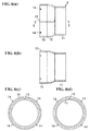
Figs. 6(a), 6(b), 6(c), and 6(d) show an outer frame single item of a frame member forming the airflow-direction adjustment device, whereinFig. 6(a) is a top view;Fig. 6(b) is a cross-sectional view taken along a line B-B inFig. 6(a); Fig. 6(c) is a front view; andFig. 6(d) is a rear view. -
Figs. 7(a), 7(b), 7(c), and 7(d) show a front frame single item of the frame member forming the airflow-direction adjustment device, whereinFig. 7(a) is a top view;Fig. 7(b) is a cross-sectional view taken along a line C-C inFig. 7(a); Fig. 7(c) is a front view; andFig. 7(d) is a rear view. -
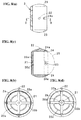
Figs. 8(a), 8(b), 8(c), and 8(d) show a housing single item forming the airflow-direction adjustment device, whereinFig. 8(a) is a top view;Fig. 8(b) is a cross-sectional view taken along a line D-D inFig. 8(a); Fig. 8(c) is a front view; andFig. 8(d) is a rear view. -
Figs. 9(a) and 9(b) show a relationship of the fin, a division plate, an operating portion, a shaft, and a gear mechanism forming the airflow-direction adjustment device, whereinFig. 9(a) is a top view; andFig. 9(b) is a view seen from an E-E line direction inFig. 9(a) . - Hereinafter, embodiments of the present invention will be explained with reference to the attached drawings. In the explanation, after a structure and an assembly of an airflow-direction adjustment device are clarified, main operations will be described. Incidentally, in the drawings,
Fig. 1 andFig. 2 are schematic views; andFig. 3(a) to Fig. 5(d) show an operating state of the airflow-direction adjustment device, andFigs. 3(b) ,4(b) , and5(b) are diagrams showing cross-sectional states taken along a line A-A, a line A1-A1, and a line A2-A2. - (Structure) As shown in
Fig. 1 andFig. 2 , an airflow-direction adjustment device 1 of the embodiments comprises ahousing 1 opening front and back ends; a pair ofvanes housing 2; agear mechanism 4 allowing an angle or a direction of eachvane nob 5 which is an operating portion operating thegear mechanism 4; and the like. Also, thehousing 2 is incorporated inside frame members, i.e. anouter frame 8 and afront frame 9 in an assembly state wherein eachvane gear mechanism 4, thenob 5, and the like are incorporated. - Here, the
outer frame 8 and thefront frame 9 can be omitted by forming an attachment portion and the like in thehousing 2. As for a material, thehousing 1, the vanes 2A and 2B, thegear mechanism 3, thenob 4, theouter frame 8, and thefront frame 9 are resin articles; however, those may be made of materials other than a resin. - As shown in
Fig. 2 andFigs. 8(a) to 8(d) , thehousing 2 has an approximately spherical shape, and an inside is formed in a shape close to a spherical shape wherein the pair ofvanes housing 2, a front end side is set as an air outlet 2a, and a back end side is set as anair inlet 2b. As shown inFig. 8(b) , the front end side includescross-shaped arm portions pivotal support portion 21 provided at a center thereof as a through hole; and aring portion 20c provided on a concentric circle with thepivotal support portion 21, and connected to thearm portions arm portions ring portion 20c. On a center inner side of the cross shape, there is formed aconcave portion 20d at a portion around thepivotal support portion 21. - On an outer circumference, there is provided a
convex portion 22 at an approximately intermediate portion of front and back. At the back end side, there are provided a pair of shaft holes 23 penetrating on the pivot line N; a pair ofengagement holes 24a penetrating in a direction intersecting the pivot line N; andpositioning portions 24 for a partition plate wherein an inner face of eachengagement hole 24a is lowered by one step. Among those, in eachshaft hole 23, there are fittedshaft portions 32 of the later-describedvanes partition plate 25 shown with imaginary lines inFig. 8(c) is positioned to be disposed in each positioningportion 24. - The
partition plate 25 is a partition dividing a back inner side of thehousing 2 into two. Namely, thepartition plate 25 has a semi-disk shape which is one size larger than that of thevanes Fig. 2 ), and there are includedclaws 26 provided in each cut face thereof. Also, thepartition plate 25 includes a concave-shapedpivotal support portion 29 provided in a middle of top and bottom or right and left of (an end face of) the straight portion; andcavities 28 respectively provided on both side faces, and wherein a portion close to thepivotal support portion 29 is lowered by one step, and which is rimed with asemicircular rib 27. Then, in theaforementioned partition plate 25, eachclaw 26 is engaged with theengagement hole 24a to be mounted inside thehousing 2. In a mounting state of thepartition plate 25, the inside of thehousing 2 is divided into two to right and left or top and bottom by thepartition plate 25 up to a vicinity of the pivot line N from a back side of thehousing 2. - Consequently, in the structure, in a state without the
vanes inlet 2b of thehousing 2, and flows in a direction of the outlet 2a, or in a state including thevanes vane inlet 2b at the two portions divided as shown inFig. 5(b) to flow in a direction of the outlet 2a in a state close to a swirl flow. - Namely, as shown in
Fig. 2 andFigs. 9(a) and 9(b) , thevanes shaft portions 32 for a pivot projected at a middle ofcurved portions 31 of the vanes; andgear portions 6 integrally formed in a middle ofstraight portions 30 of the vanes. Theshaft portion 32 and thegear portion 6 are provided on the aforementioned pivot line N. Also, theshaft portion 32 of each vane is fitted into the correspondingshaft hole 23 of thehousing 2, and thegear portion 6 of each vane engages one portion of agear 7 provided on a back end side of ashaft 4 respectively. - Thereby, each
vane partition plate 25 inside thehousing 2, and supported turnably in a front-and-back direction as the supporting point of the common pivot line N (theshaft portion 32 and thegear portion 6 provided on the pivot line). - In that case, the
shaft 4 includes a flange portion 4a provided slightly just in front of a front end; a pair ofclaws 4b provided around the shaft just in front of the flange portion 4a; thegear 7 integrally formed at the back end side, and engaging eachgear portion 6; and aprotrusion 4c projected on an outer end face of thegear 7. Theclaws 4b engage alocking hole portion 5b connected to a hole portion 5a when theclaws 4b are inserted into the hole portion 5a of thenob 5. Thegear 7 and thegear portion 6 only have to have a relationship of transmitting a rotational movement between intersecting two shafts. Usually, thegear 7 and thegear portion 6 are formed by a bevel gear such as a timer gear, a spiral bevel gear, an oblique gear, and the like. - In the
aforementioned shaft 4, in a state wherein a front end side is inserted into the through hole of the aforementionedpivotal support portion 21, and the flange portion 4a is fitted into theconcave portion 20d inside thepivotal support portion 21, thenob 5 which is the operating portion is mounted on a projecting portion inserted outwardly through the aforementioned through hole. Then, in theshaft 4, in a state retained by the flange portion 4a and thenob 5, a back side portion is disposed between thevane 3A and thevane 3B, and thegear 7 is engaged with thegear portion 6 of each vane. - On the other hand, as shown in
Fig. 1 ,Figs. 3(a) to 3(d) , andFigs. 6 (a) to 6(d) , theouter frame 8 is a main member portion of the frame member, and the inside has a shape into which thehousing 2 can fit. Namely, theouter frame 8 is formed by a large-diameter cylinder portion 10 on a front side; a small-diameter cylinder portion 11 on a back side; and a curved-face cylinder portion 12 in a middle therebetween. In the large-diameter cylinder portion 10 and the curved-face cylinder portion 12, there is provided astraight guide groove 13 guiding theconvex portion 22 of thehousing 2. In the large-diameter cylinder portion 10, there are providedprotrusions 14 at four portions at equal intervals on the circumference of the large-diameter cylinder portion 10. - As shown in
Figs. 7(a) to 7(d) , thefront frame 9 is formed by an approximately ring shape connected to theouter frame 8. In thefront frame 9, there are provided fourengagement holes 15 corresponding to theprotrusions 14; twoattachment pieces 16 protruding between the engagement holes 15; aninner flange portion 17 forming acircular gap 18 between theinner flange portion 17 and an outer circumference; and a positioningsmall protrusion 19 protruding inside thegap 18, and engaging theguide groove 13 of the outer frame. Incidentally, thereference sign 17a is a die-cutting notch corresponding to thesmall protrusion 19. - (Assembly) Hereinafter, one example of an assembly procedure of the aforementioned respective members will be explained. In the example, as shown in
Fig. 1 andFig. 2 , after theshaft 4 is incorporated relative to thehousing 2 through thenob 5, thevanes partition plate 25 are assembled. - For further details, first, in the
shaft 4, when the front end side is inserted into the through hole of thepivotal support portion 21 through the housing from the flange portion 4a, the flange portion 4a comes to a state wherein the flange portion 4a fits into theconcave portion 20d. After that, thenob 5 is mounted on the front end side of theshaft 4 protruding to an outside of thepivotal support portion 21. In that case, after the pair ofclaws 4b is inserted into the hole portion 5a of the nob, the pair ofclaws 4b engages thelocking hole portion 5b connected to the hole portion 5a. Thereby, thenob 5 is mounted on theshaft 4. Theshaft 4 is turnably supported by thepivotal support portion 21 in a state wherein a front side is retained through the flange portion 4a and thenob 5. - Next, the
partition plate 25 is assembled to thehousing 2. In that case, in thepartition plate 25, upper and lower cut portions fit into thepositioning portions 24 relative to the back inner side of thehousing 2, and eachclaw 26 is engaged with theengagement hole 24a, so that thepartition plate 25 is mounted on thehousing 2. In the mounting state of thepartition plate 25, in theshaft 4, theprotrusion 4c on a back end face fits into thepivotal support portion 29 of thepartition plate 25, so that theshaft 4 is turnably supported in the fitting state of a back side. - Next, the
vanes housing 2. In that case, in thevane 3A and thevane 3B, theshaft portion 32 fits into the correspondingshaft hole 23 on a housing side, and thegear portion 6 is engaged with thegear 7. At that time, in thegear portion 6, as presumed fromFig. 9(b) , in a state wherein one portion is engaged with thegear 7, the remaining portions enter into thecavity 28 of thepartition plate 25 to be released. In the assembly state, eachvane shaft portion 32 and thegear portion 6 disposed on the aforementioned pivot line N. - As mentioned above, an assembly member itself wherein the
shaft 4, thenob 5, thepartition plate 25, and thevanes housing 2 can be used as the airflow-direction adjustment device 1; however, in the example, the assembly member thereof is used as the airflow-direction adjustment device 1 in an aspect wherein the assembly member thereof is disposed inside theouter frame 8 and thefront frame 9 which are the frame members. In that case, in the aforementioned assembly member, as shown inFig. 1 , andFigs. 3(a) to 3(d) , after the assembly member is inserted into the outer frame in a state wherein theconvex portion 22 of thehousing 2 fits into theguide groove 13 relative to theouter frame 8, thefront frame 9 is connected to theouter frame 8, so that the assembly member is disposed inside bothframes front frame 9, an end side of the large-diameter cylinder portion 10 fits into thegap 18 relative to theouter frame 8, and simultaneously, when thesmall protrusion 19 is approached to fit into theguide groove 13, eachprotrusion 14 engages thecorresponding engagement hole 15 to be connected. Thereby, the assembly member is completed as the airflow-direction adjustment device 1 shown inFig. 1 , andFig. 3 (a) to Fig. 5(d) . - (Operations) Hereinafter, the main operations of the airflow-
direction adjustment device 1 made as mentioned above will be described. - (1)
Figs. 3(a) to 3(d) show a closed state wherein eachvane shaft portion 32 and thegear portion 6 to close between the air outlet 2a and theair inlet 2b. Therefore, in the closed state, the air sucked into theair inlet 2b is inhibited from flowing toward the air outlet 2a by eachvane - (2)
Figs 4(a) to 4(d) show an open state, for example, wherein eachvane shaft portion 32 and thegear portion 6 by a turning operation of thenob 5 to be switched approximately horizontally from the closed state inFigs. 3(a) to 3(d) . In the switchover, eachvane gear 7 on the gear mechanism, i.e. a shaft side, and thegear portion 6 on eachvane air inlet 2b flows to an air outlet 2a side in a state divided into right and left at thepartition plate 25, and further divided into top and bottom by thevanes arm portions ring portion 20c. - (3)
Figs. 5(a) to 5(d) show the open state, for example, wherein eachvane shaft portion 32 and thegear portion 6 by the turning operation of thenob 5 to be switched obliquely from the closed state inFigs. 3(a) to 3(d) . In the switchover, eachvane gear 7 on the gear mechanism, i.e. the shaft side, and thegear portion 6 on eachvane air inlet 2b is divided into the right and left at thepartition plate 25, and flows in an airflow direction in an X direction in addition to a change of the airflow direction on a curved surface inside thehousing 2 by thevanes vane - (4) In the aforementioned airflow-
direction adjustment device 1, the fin is formed by the pair ofvanes vane direction adjustment device 1, the number of members can be reduced, and weight can be reduced so as to become easy to reduce a cost as well. Also, in the structure, the pair ofvanes housing 2, and is turned as the supporting point on the common pivot line N set in a plate width direction, so that, for example, even if a large impact is applied, a possibility that both vanes interfere with each other can be easily eliminated so as to improve durability as well. - (5) Simultaneously, the airflow-
direction adjustment device 1 is switched from the closed state inFigs. 3(a) to 3(d) wherein thevanes gear 7 on the gear mechanism, i.e. the shaft side, and thegear portion 6 on eachvane Figs. 4(a) to 4(d) ,Figs. 5(a) to 5(d) , and the like which allows the flow of air and varies the airflow direction. Consequently, as for structure characteristics, even with a few vanes, i.e. the pair ofvanes - (6) Simultaneously, in the airflow-
direction adjustment device 1, the gear mechanism, for turning a plurality of vanes in synchronization with a rotation of an operating portion such as thenob 5 and the like, is formed by thegear portion 6 provided on the pivot line N of eachvane gear 7 is integrally rotated with thenob 5, and engaged with thegear portion 6 of each vane. Accordingly, thevanes Patent Document 2, the airflow-direction adjustment device 1 can be simplified, and compared to a structure wherein both gear portions of the pedestal are directly engaged as shown in thePatent Document 1, an excellent engagement state can be easily maintained. - (7) Simultaneously, in the airflow-
direction adjustment device 1, eachvane curved portion 31 is axially supported on ahousing 2 side, and thegear portion 6 is provided in thestraight portion 30, so that a vane shape becomes the most suitable for an aspect wherein the inside of thehousing 2 is close to the approximately spherical shape, and thepartition plate 25 can be easily added as well. Incidentally, thepartition wall 25 may be omitted (in that case, theprotrusion 4c provided in theshaft 4 becomes unnecessary as well). Also, thenob 5 which is the operating portion is mounted on theshaft 4 with thegear 7. Theshaft 4 is easily and reliably supported by thepivotal support portion 21 on the housing side and thepivotal support portion 29 on apartition plate 25 side. - Incidentally, in the airflow-direction adjustment device of the present invention, the details can be modified or developed with reference to the aforementioned explanation provided that they comprise a structure specified in the first aspect. As for one example, there is shown the embodiment wherein the housing is positioned to be fixed in the frame members; however, for example, relative to the frame members, a turning groove may be provided in a circumferential direction of the frame members or the outer frame from the
guide groove 13 so as to turn to the right and left along the turning groove only by a predetermined angle to carry out the airflow-direction adjustment further multilaterally. - Incidentally, all contents of the specification, claims, drawings, and abstract of Japanese Patent Application No.
2013-239461 filed on November 20, 2013
Claims (7)
- An airflow-direction adjustment device, comprising:a housing wherein a front end side is set as an air outlet and a back end side is set as an air inlet;a fin turnably supported inside the housing; anda gear mechanism for adjusting a direction of the fin by a rotation of an operating portion,wherein the fin comprises a pair of vanes disposed on right and left or top and bottom inside the housing, and
each vane is turnably supported in a front-and-back direction of the housing respectively as a supporting point on a common pivot line set in a plate width direction. - An airflow-direction adjustment device according to claim 1, wherein the respective vanes are switched from a closed state rotated relatively in opposite directions through the gear mechanism to substantially inhibit a flow of air from an air inlet side toward an air outlet side, to an open state allowing the flow of air and varying an airflow direction.
- An airflow-direction adjustment device according to claim 1 or 2, wherein the gear mechanism includes gear portions provided on the pivot line of the vanes, and a gear integrally rotated with the operating portion and engaging the gear portions of the vanes.
- An airflow-direction adjustment device according to any one of claims 1 to 3, wherein the housing has an approximately spherical shape, and opens at front and back ends, and divided into two by a division plate up to a vicinity on the pivot line from an air inlet side.
- An airflow-direction adjustment device according to claim 3 or 4, wherein each vane is formed in an approximately semi-disk shape, is axially supported at a curved portion on a housing side, and is provided with the gear portion in a straight portion.
- An airflow-direction adjustment device according to claim 4 or 5, wherein the operating portion includes a shaft provided with the gear, and in the shaft, a front end side is turnably supported in a pivotal support portion provided in the housing, and a back end side is turnably supported in a pivotal support portion provided in the division plate.
- An airflow-direction adjustment device according to any of claims 1 to 6, further comprising a frame member incorporating the housing, and attached to an installation portion through the frame member.
Applications Claiming Priority (2)
| Application Number | Priority Date | Filing Date | Title |
|---|---|---|---|
| JP2013239461 | 2013-11-20 | ||
| PCT/JP2014/080492 WO2015076254A1 (en) | 2013-11-20 | 2014-11-18 | Airflow direction adjustment device |
Publications (3)
| Publication Number | Publication Date |
|---|---|
| EP3072718A1 true EP3072718A1 (en) | 2016-09-28 |
| EP3072718A4 EP3072718A4 (en) | 2017-07-26 |
| EP3072718B1 EP3072718B1 (en) | 2019-06-19 |
Family
ID=53179516
Family Applications (1)
| Application Number | Title | Priority Date | Filing Date |
|---|---|---|---|
| EP14863555.0A Active EP3072718B1 (en) | 2013-11-20 | 2014-11-18 | Airflow direction adjustment device |
Country Status (6)
| Country | Link |
|---|---|
| US (1) | US10317107B2 (en) |
| EP (1) | EP3072718B1 (en) |
| JP (1) | JP6099285B2 (en) |
| KR (1) | KR101647560B1 (en) |
| CN (1) | CN105745100B (en) |
| WO (1) | WO2015076254A1 (en) |
Cited By (1)
| Publication number | Priority date | Publication date | Assignee | Title |
|---|---|---|---|---|
| WO2020124216A1 (en) | 2018-12-21 | 2020-06-25 | Bombardier Inc. | Air deflector and system including the air deflector |
Families Citing this family (22)
| Publication number | Priority date | Publication date | Assignee | Title |
|---|---|---|---|---|
| DE102015118549B4 (en) * | 2015-05-11 | 2017-05-04 | Dr. Schneider Kunststoffwerke Gmbh | Device for controlling an air flow |
| CN105402872B (en) * | 2015-12-18 | 2019-07-30 | 广东美的制冷设备有限公司 | Air deflection assemblies and air conditioner for air conditioner |
| CN105465987B (en) * | 2015-12-18 | 2019-07-30 | 广东美的制冷设备有限公司 | Air deflection assemblies and air conditioner for air conditioner |
| DE102015017009B4 (en) * | 2015-12-30 | 2018-04-26 | Faurecia Innenraum Systeme Gmbh | outlet device |
| KR102374583B1 (en) * | 2016-02-17 | 2022-03-15 | 유닉스 컴퍼니 리미티드 | Ventilation register |
| KR102007895B1 (en) | 2017-08-11 | 2019-08-06 | 주식회사 니프코코리아 | Air ventilator for automobile |
| CN107520666A (en) * | 2017-09-30 | 2017-12-29 | 镇江中焱数控设备有限公司 | A kind of new chip removal device |
| KR102406067B1 (en) | 2017-10-25 | 2022-06-08 | 현대자동차주식회사 | Variable air vent |
| CN108361944B (en) * | 2018-04-28 | 2023-11-17 | 安徽扬子空调股份有限公司 | Air supply system and air conditioner |
| US11235643B2 (en) * | 2018-11-27 | 2022-02-01 | Scott Bradley Baker | Air vent assembly and control system |
| CN109910562B (en) * | 2019-03-13 | 2021-08-03 | 曼德电子电器有限公司 | Air conditioner air outlet duct air flow adjusting mechanism |
| CN109910560B (en) * | 2019-03-13 | 2021-08-03 | 曼德电子电器有限公司 | Air passage control mechanism of air conditioner air outlet channel |
| DE102020102896A1 (en) | 2020-02-05 | 2021-08-05 | Fischer Automotive Systems Gmbh & Co. Kg | Ventilation device |
| US11448452B2 (en) * | 2020-06-04 | 2022-09-20 | Heatcraft Refrigeration Products Llc | Swivel fan guards |
| CN111912003B (en) * | 2020-06-29 | 2021-12-28 | 西安交通大学 | Air supply device of air conditioner |
| CN111890880A (en) * | 2020-08-13 | 2020-11-06 | 芜湖鑫沃汽车零部件有限公司 | Air outlet structure of automobile air conditioner |
| CN112146257A (en) * | 2020-09-27 | 2020-12-29 | 广州誉良企业管理有限公司 | Office central air-conditioning auxiliary device capable of avoiding uneven wind distribution |
| CN112793395B (en) * | 2021-04-13 | 2021-07-02 | 宁波均胜群英汽车系统股份有限公司 | Manually-controlled circular air outlet |
| CA3225988A1 (en) * | 2021-07-13 | 2023-01-19 | Hussmann Corporation | Refrigerated merchandiser with tunable airflow discharge |
| KR102398645B1 (en) * | 2021-09-10 | 2022-05-16 | 김형진 | Air conditioning system with ion cluster device |
| USD989929S1 (en) * | 2021-11-02 | 2023-06-20 | Classic Auto Air Manufacturing LP | Vent accessory for vehicle heating and air conditioning systems |
| USD989928S1 (en) * | 2021-11-02 | 2023-06-20 | Classic Auto Air Manufacturing LP | Vent accessory for vehicle heating and air conditioning systems |
Family Cites Families (28)
| Publication number | Priority date | Publication date | Assignee | Title |
|---|---|---|---|---|
| GB1128521A (en) * | 1965-05-22 | 1968-09-25 | Clear Hooters Ltd | Nozzle for a heating or ventilating system |
| GB1161111A (en) * | 1965-05-25 | 1969-08-13 | Humber Ltd | Ventilating valves for vehicles |
| GB1385874A (en) * | 1971-07-06 | 1975-03-05 | Clear Hooters Ltd | Ventilating nozzle |
| GB1402755A (en) * | 1972-04-04 | 1975-08-13 | Clear Hooters Ltd | Ventilating nozzle including a universally swivellable nozzle mem ber |
| GB1396993A (en) * | 1972-04-19 | 1975-06-11 | Clear Hooters Ltd | Ventilating nozzle including a universally swivellable nozzle member and a flow control valve |
| DE2413628A1 (en) * | 1974-03-21 | 1975-10-02 | Kammerer Gmbh M | DUESE FOR HEATING AND VENTILATION SYSTEMS IN MOTOR VEHICLES |
| US4092907A (en) * | 1974-09-07 | 1978-06-06 | Daimler-Benz Aktiengesellschaft | Outlet nozzle for heating and venting systems of automobiles |
| IT1055617B (en) * | 1974-09-07 | 1982-01-11 | Daimler Benz Ag | BICCHETTA FOR HEATING AND VENTILATION SYSTEMS ON BOARD MOTOR VEHICLES |
| JPS60184713U (en) * | 1984-05-19 | 1985-12-07 | 和光化成工業株式会社 | air outlet device |
| JPH04302940A (en) * | 1991-03-29 | 1992-10-26 | Toyoda Gosei Co Ltd | Supply grill |
| JPH0566449U (en) * | 1992-02-12 | 1993-09-03 | 豊田合成株式会社 | Air flow controller |
| JPH08197940A (en) | 1995-01-30 | 1996-08-06 | Nippon Plast Co Ltd | Wind direction adjusting device |
| CN2239595Y (en) * | 1995-06-30 | 1996-11-06 | 章日金 | Automobile air conditioner outlet |
| KR100306435B1 (en) * | 1999-07-20 | 2001-09-13 | 이계안 | Air ventilation grille for automobile |
| CN1285288A (en) * | 1999-08-23 | 2001-02-28 | 圣州企业股份有限公司 | Implement for blowing cold/hot air in car |
| DE10223660B4 (en) * | 2002-05-28 | 2013-10-24 | Volkswagen Ag | Air vent for a vehicle, in particular for a motor vehicle |
| JP2008002714A (en) * | 2006-06-20 | 2008-01-10 | Toyota Motor Corp | Air supply port structure |
| CN101293472B (en) * | 2008-05-13 | 2011-11-16 | 奇瑞汽车股份有限公司 | Air-out regulating device of automobile air conditioner |
| DE102009041532B4 (en) | 2009-09-15 | 2011-11-24 | Trw Automotive Electronics & Components Gmbh | Swirl device for an air vent |
| DE102010014575B3 (en) * | 2010-04-12 | 2011-11-17 | Trw Automotive Electronics & Components Gmbh | air vents |
| JP5460478B2 (en) | 2010-06-18 | 2014-04-02 | 株式会社パイオラックス | Locking device |
| JP6104534B2 (en) * | 2012-08-08 | 2017-03-29 | 豊和化成株式会社 | register |
| JP6491874B2 (en) * | 2013-12-20 | 2019-03-27 | 日本プラスト株式会社 | Wind direction adjustment device |
| US9707826B2 (en) * | 2014-07-31 | 2017-07-18 | GM Global Technology Operations LLC | Airflow outlet |
| US10131209B2 (en) * | 2014-11-07 | 2018-11-20 | GM Global Technology Operations LLC | Airflow outlet assembly and a passenger compartment for a vehicle |
| US9895961B2 (en) * | 2014-11-07 | 2018-02-20 | GM Global Technology Operations LLC | Airflow outlet |
| US9718329B2 (en) * | 2015-06-15 | 2017-08-01 | GM Global Technology Operations LLC | Airflow outlet assembly and a passenger compartment for a vehicle |
| JP6436013B2 (en) * | 2015-08-04 | 2018-12-12 | 豊田合成株式会社 | Round air conditioning register |
-
2014
- 2014-11-18 WO PCT/JP2014/080492 patent/WO2015076254A1/en active Application Filing
- 2014-11-18 US US15/037,495 patent/US10317107B2/en active Active
- 2014-11-18 CN CN201480063071.4A patent/CN105745100B/en active Active
- 2014-11-18 JP JP2015549153A patent/JP6099285B2/en active Active
- 2014-11-18 EP EP14863555.0A patent/EP3072718B1/en active Active
- 2014-11-19 KR KR1020140161772A patent/KR101647560B1/en active IP Right Grant
Cited By (2)
| Publication number | Priority date | Publication date | Assignee | Title |
|---|---|---|---|---|
| WO2020124216A1 (en) | 2018-12-21 | 2020-06-25 | Bombardier Inc. | Air deflector and system including the air deflector |
| EP3899377A4 (en) * | 2018-12-21 | 2022-08-31 | MHI RJ Aviation ULC | Air deflector and system including the air deflector |
Also Published As
| Publication number | Publication date |
|---|---|
| EP3072718B1 (en) | 2019-06-19 |
| US20160282008A1 (en) | 2016-09-29 |
| KR101647560B1 (en) | 2016-08-10 |
| KR20150058074A (en) | 2015-05-28 |
| EP3072718A4 (en) | 2017-07-26 |
| JP6099285B2 (en) | 2017-03-22 |
| CN105745100A (en) | 2016-07-06 |
| CN105745100B (en) | 2018-06-15 |
| US10317107B2 (en) | 2019-06-11 |
| WO2015076254A1 (en) | 2015-05-28 |
| JPWO2015076254A1 (en) | 2017-03-16 |
Similar Documents
| Publication | Publication Date | Title |
|---|---|---|
| EP3072718B1 (en) | Airflow direction adjustment device | |
| JP6094366B2 (en) | Damper opening and closing device | |
| EP3199393B1 (en) | Air vent for vehicle | |
| US8113672B2 (en) | Outer mirror | |
| JP5656957B2 (en) | register | |
| US20160361979A1 (en) | Airflow outlet assembly and a passenger compartment for a vehicle | |
| US10131209B2 (en) | Airflow outlet assembly and a passenger compartment for a vehicle | |
| JP2014034280A (en) | Register | |
| US11088596B2 (en) | Motor cooling fan unit, motor, and exhaust unit | |
| JP2016000609A (en) | Wind direction adjusting device | |
| JP2017013783A (en) | Wind direction adjustment device for vehicle | |
| US20150183300A1 (en) | Air vent apparatus for vehicle | |
| JP2013199178A (en) | Grill shutter for vehicle | |
| JP5340874B2 (en) | Air blowing device | |
| JP5733203B2 (en) | Air conditioning register | |
| JP2009046069A (en) | Ventilator for vehicle | |
| JP5928932B2 (en) | register | |
| JP6097137B2 (en) | register | |
| JP5568421B2 (en) | Ventilator | |
| JP2016078493A (en) | register | |
| JP2016053426A (en) | Air blowout device | |
| JP6397201B2 (en) | Air blowing device for vehicle | |
| JP5704991B2 (en) | register | |
| JP6187654B2 (en) | Damper opening and closing device | |
| EP1743790A1 (en) | Air diffuser for vehicle dashboards |
Legal Events
| Date | Code | Title | Description |
|---|---|---|---|
| PUAI | Public reference made under article 153(3) epc to a published international application that has entered the european phase |
Free format text: ORIGINAL CODE: 0009012 |
|
| 17P | Request for examination filed |
Effective date: 20160607 |
|
| AK | Designated contracting states |
Kind code of ref document: A1 Designated state(s): AL AT BE BG CH CY CZ DE DK EE ES FI FR GB GR HR HU IE IS IT LI LT LU LV MC MK MT NL NO PL PT RO RS SE SI SK SM TR |
|
| AX | Request for extension of the european patent |
Extension state: BA ME |
|
| DAX | Request for extension of the european patent (deleted) | ||
| RIC1 | Information provided on ipc code assigned before grant |
Ipc: B64D 13/00 20060101ALI20170530BHEP Ipc: F24F 13/06 20060101ALI20170530BHEP Ipc: F24F 13/065 20060101ALI20170530BHEP Ipc: B60H 1/34 20060101AFI20170530BHEP |
|
| RIC1 | Information provided on ipc code assigned before grant |
Ipc: B64D 13/00 20060101ALI20170613BHEP Ipc: F24F 13/06 20060101ALI20170613BHEP Ipc: B60H 1/34 20060101AFI20170613BHEP Ipc: F24F 13/065 20060101ALI20170613BHEP |
|
| A4 | Supplementary search report drawn up and despatched |
Effective date: 20170622 |
|
| STAA | Information on the status of an ep patent application or granted ep patent |
Free format text: STATUS: EXAMINATION IS IN PROGRESS |
|
| 17Q | First examination report despatched |
Effective date: 20180511 |
|
| GRAP | Despatch of communication of intention to grant a patent |
Free format text: ORIGINAL CODE: EPIDOSNIGR1 |
|
| STAA | Information on the status of an ep patent application or granted ep patent |
Free format text: STATUS: GRANT OF PATENT IS INTENDED |
|
| INTG | Intention to grant announced |
Effective date: 20190130 |
|
| GRAS | Grant fee paid |
Free format text: ORIGINAL CODE: EPIDOSNIGR3 |
|
| GRAA | (expected) grant |
Free format text: ORIGINAL CODE: 0009210 |
|
| STAA | Information on the status of an ep patent application or granted ep patent |
Free format text: STATUS: THE PATENT HAS BEEN GRANTED |
|
| AK | Designated contracting states |
Kind code of ref document: B1 Designated state(s): AL AT BE BG CH CY CZ DE DK EE ES FI FR GB GR HR HU IE IS IT LI LT LU LV MC MK MT NL NO PL PT RO RS SE SI SK SM TR |
|
| REG | Reference to a national code |
Ref country code: GB Ref legal event code: FG4D |
|
| REG | Reference to a national code |
Ref country code: CH Ref legal event code: EP |
|
| REG | Reference to a national code |
Ref country code: IE Ref legal event code: FG4D |
|
| REG | Reference to a national code |
Ref country code: DE Ref legal event code: R096 Ref document number: 602014048843 Country of ref document: DE |
|
| REG | Reference to a national code |
Ref country code: AT Ref legal event code: REF Ref document number: 1145020 Country of ref document: AT Kind code of ref document: T Effective date: 20190715 |
|
| REG | Reference to a national code |
Ref country code: NL Ref legal event code: MP Effective date: 20190619 |
|
| PG25 | Lapsed in a contracting state [announced via postgrant information from national office to epo] |
Ref country code: HR Free format text: LAPSE BECAUSE OF FAILURE TO SUBMIT A TRANSLATION OF THE DESCRIPTION OR TO PAY THE FEE WITHIN THE PRESCRIBED TIME-LIMIT Effective date: 20190619 Ref country code: SE Free format text: LAPSE BECAUSE OF FAILURE TO SUBMIT A TRANSLATION OF THE DESCRIPTION OR TO PAY THE FEE WITHIN THE PRESCRIBED TIME-LIMIT Effective date: 20190619 Ref country code: AL Free format text: LAPSE BECAUSE OF FAILURE TO SUBMIT A TRANSLATION OF THE DESCRIPTION OR TO PAY THE FEE WITHIN THE PRESCRIBED TIME-LIMIT Effective date: 20190619 Ref country code: FI Free format text: LAPSE BECAUSE OF FAILURE TO SUBMIT A TRANSLATION OF THE DESCRIPTION OR TO PAY THE FEE WITHIN THE PRESCRIBED TIME-LIMIT Effective date: 20190619 Ref country code: NO Free format text: LAPSE BECAUSE OF FAILURE TO SUBMIT A TRANSLATION OF THE DESCRIPTION OR TO PAY THE FEE WITHIN THE PRESCRIBED TIME-LIMIT Effective date: 20190919 Ref country code: LT Free format text: LAPSE BECAUSE OF FAILURE TO SUBMIT A TRANSLATION OF THE DESCRIPTION OR TO PAY THE FEE WITHIN THE PRESCRIBED TIME-LIMIT Effective date: 20190619 |
|
| REG | Reference to a national code |
Ref country code: LT Ref legal event code: MG4D |
|
| PG25 | Lapsed in a contracting state [announced via postgrant information from national office to epo] |
Ref country code: BG Free format text: LAPSE BECAUSE OF FAILURE TO SUBMIT A TRANSLATION OF THE DESCRIPTION OR TO PAY THE FEE WITHIN THE PRESCRIBED TIME-LIMIT Effective date: 20190919 Ref country code: GR Free format text: LAPSE BECAUSE OF FAILURE TO SUBMIT A TRANSLATION OF THE DESCRIPTION OR TO PAY THE FEE WITHIN THE PRESCRIBED TIME-LIMIT Effective date: 20190920 Ref country code: RS Free format text: LAPSE BECAUSE OF FAILURE TO SUBMIT A TRANSLATION OF THE DESCRIPTION OR TO PAY THE FEE WITHIN THE PRESCRIBED TIME-LIMIT Effective date: 20190619 Ref country code: LV Free format text: LAPSE BECAUSE OF FAILURE TO SUBMIT A TRANSLATION OF THE DESCRIPTION OR TO PAY THE FEE WITHIN THE PRESCRIBED TIME-LIMIT Effective date: 20190619 |
|
| REG | Reference to a national code |
Ref country code: AT Ref legal event code: MK05 Ref document number: 1145020 Country of ref document: AT Kind code of ref document: T Effective date: 20190619 |
|
| PG25 | Lapsed in a contracting state [announced via postgrant information from national office to epo] |
Ref country code: EE Free format text: LAPSE BECAUSE OF FAILURE TO SUBMIT A TRANSLATION OF THE DESCRIPTION OR TO PAY THE FEE WITHIN THE PRESCRIBED TIME-LIMIT Effective date: 20190619 Ref country code: PT Free format text: LAPSE BECAUSE OF FAILURE TO SUBMIT A TRANSLATION OF THE DESCRIPTION OR TO PAY THE FEE WITHIN THE PRESCRIBED TIME-LIMIT Effective date: 20191021 Ref country code: NL Free format text: LAPSE BECAUSE OF FAILURE TO SUBMIT A TRANSLATION OF THE DESCRIPTION OR TO PAY THE FEE WITHIN THE PRESCRIBED TIME-LIMIT Effective date: 20190619 Ref country code: RO Free format text: LAPSE BECAUSE OF FAILURE TO SUBMIT A TRANSLATION OF THE DESCRIPTION OR TO PAY THE FEE WITHIN THE PRESCRIBED TIME-LIMIT Effective date: 20190619 Ref country code: AT Free format text: LAPSE BECAUSE OF FAILURE TO SUBMIT A TRANSLATION OF THE DESCRIPTION OR TO PAY THE FEE WITHIN THE PRESCRIBED TIME-LIMIT Effective date: 20190619 Ref country code: CZ Free format text: LAPSE BECAUSE OF FAILURE TO SUBMIT A TRANSLATION OF THE DESCRIPTION OR TO PAY THE FEE WITHIN THE PRESCRIBED TIME-LIMIT Effective date: 20190619 Ref country code: SK Free format text: LAPSE BECAUSE OF FAILURE TO SUBMIT A TRANSLATION OF THE DESCRIPTION OR TO PAY THE FEE WITHIN THE PRESCRIBED TIME-LIMIT Effective date: 20190619 |
|
| PG25 | Lapsed in a contracting state [announced via postgrant information from national office to epo] |
Ref country code: IS Free format text: LAPSE BECAUSE OF FAILURE TO SUBMIT A TRANSLATION OF THE DESCRIPTION OR TO PAY THE FEE WITHIN THE PRESCRIBED TIME-LIMIT Effective date: 20191019 Ref country code: SM Free format text: LAPSE BECAUSE OF FAILURE TO SUBMIT A TRANSLATION OF THE DESCRIPTION OR TO PAY THE FEE WITHIN THE PRESCRIBED TIME-LIMIT Effective date: 20190619 Ref country code: IT Free format text: LAPSE BECAUSE OF FAILURE TO SUBMIT A TRANSLATION OF THE DESCRIPTION OR TO PAY THE FEE WITHIN THE PRESCRIBED TIME-LIMIT Effective date: 20190619 Ref country code: ES Free format text: LAPSE BECAUSE OF FAILURE TO SUBMIT A TRANSLATION OF THE DESCRIPTION OR TO PAY THE FEE WITHIN THE PRESCRIBED TIME-LIMIT Effective date: 20190619 |
|
| PG25 | Lapsed in a contracting state [announced via postgrant information from national office to epo] |
Ref country code: TR Free format text: LAPSE BECAUSE OF FAILURE TO SUBMIT A TRANSLATION OF THE DESCRIPTION OR TO PAY THE FEE WITHIN THE PRESCRIBED TIME-LIMIT Effective date: 20190619 |
|
| PG25 | Lapsed in a contracting state [announced via postgrant information from national office to epo] |
Ref country code: DK Free format text: LAPSE BECAUSE OF FAILURE TO SUBMIT A TRANSLATION OF THE DESCRIPTION OR TO PAY THE FEE WITHIN THE PRESCRIBED TIME-LIMIT Effective date: 20190619 Ref country code: PL Free format text: LAPSE BECAUSE OF FAILURE TO SUBMIT A TRANSLATION OF THE DESCRIPTION OR TO PAY THE FEE WITHIN THE PRESCRIBED TIME-LIMIT Effective date: 20190619 |
|
| PG25 | Lapsed in a contracting state [announced via postgrant information from national office to epo] |
Ref country code: IS Free format text: LAPSE BECAUSE OF FAILURE TO SUBMIT A TRANSLATION OF THE DESCRIPTION OR TO PAY THE FEE WITHIN THE PRESCRIBED TIME-LIMIT Effective date: 20200224 |
|
| REG | Reference to a national code |
Ref country code: DE Ref legal event code: R097 Ref document number: 602014048843 Country of ref document: DE |
|
| REG | Reference to a national code |
Ref country code: CH Ref legal event code: PL |
|
| PLBE | No opposition filed within time limit |
Free format text: ORIGINAL CODE: 0009261 |
|
| STAA | Information on the status of an ep patent application or granted ep patent |
Free format text: STATUS: NO OPPOSITION FILED WITHIN TIME LIMIT |
|
| PG2D | Information on lapse in contracting state deleted |
Ref country code: IS |
|
| PG25 | Lapsed in a contracting state [announced via postgrant information from national office to epo] |
Ref country code: CH Free format text: LAPSE BECAUSE OF NON-PAYMENT OF DUE FEES Effective date: 20191130 Ref country code: LU Free format text: LAPSE BECAUSE OF NON-PAYMENT OF DUE FEES Effective date: 20191118 Ref country code: LI Free format text: LAPSE BECAUSE OF NON-PAYMENT OF DUE FEES Effective date: 20191130 Ref country code: MC Free format text: LAPSE BECAUSE OF FAILURE TO SUBMIT A TRANSLATION OF THE DESCRIPTION OR TO PAY THE FEE WITHIN THE PRESCRIBED TIME-LIMIT Effective date: 20190619 |
|
| 26N | No opposition filed |
Effective date: 20200603 |
|
| REG | Reference to a national code |
Ref country code: BE Ref legal event code: MM Effective date: 20191130 |
|
| PG25 | Lapsed in a contracting state [announced via postgrant information from national office to epo] |
Ref country code: SI Free format text: LAPSE BECAUSE OF FAILURE TO SUBMIT A TRANSLATION OF THE DESCRIPTION OR TO PAY THE FEE WITHIN THE PRESCRIBED TIME-LIMIT Effective date: 20190619 |
|
| GBPC | Gb: european patent ceased through non-payment of renewal fee |
Effective date: 20191118 |
|
| PG25 | Lapsed in a contracting state [announced via postgrant information from national office to epo] |
Ref country code: FR Free format text: LAPSE BECAUSE OF NON-PAYMENT OF DUE FEES Effective date: 20191130 Ref country code: GB Free format text: LAPSE BECAUSE OF NON-PAYMENT OF DUE FEES Effective date: 20191118 Ref country code: IE Free format text: LAPSE BECAUSE OF NON-PAYMENT OF DUE FEES Effective date: 20191118 |
|
| PG25 | Lapsed in a contracting state [announced via postgrant information from national office to epo] |
Ref country code: BE Free format text: LAPSE BECAUSE OF NON-PAYMENT OF DUE FEES Effective date: 20191130 |
|
| PG25 | Lapsed in a contracting state [announced via postgrant information from national office to epo] |
Ref country code: CY Free format text: LAPSE BECAUSE OF FAILURE TO SUBMIT A TRANSLATION OF THE DESCRIPTION OR TO PAY THE FEE WITHIN THE PRESCRIBED TIME-LIMIT Effective date: 20190619 |
|
| PG25 | Lapsed in a contracting state [announced via postgrant information from national office to epo] |
Ref country code: MT Free format text: LAPSE BECAUSE OF FAILURE TO SUBMIT A TRANSLATION OF THE DESCRIPTION OR TO PAY THE FEE WITHIN THE PRESCRIBED TIME-LIMIT Effective date: 20190619 Ref country code: HU Free format text: LAPSE BECAUSE OF FAILURE TO SUBMIT A TRANSLATION OF THE DESCRIPTION OR TO PAY THE FEE WITHIN THE PRESCRIBED TIME-LIMIT; INVALID AB INITIO Effective date: 20141118 |
|
| PG25 | Lapsed in a contracting state [announced via postgrant information from national office to epo] |
Ref country code: MK Free format text: LAPSE BECAUSE OF FAILURE TO SUBMIT A TRANSLATION OF THE DESCRIPTION OR TO PAY THE FEE WITHIN THE PRESCRIBED TIME-LIMIT Effective date: 20190619 |
|
| PGFP | Annual fee paid to national office [announced via postgrant information from national office to epo] |
Ref country code: DE Payment date: 20230929 Year of fee payment: 10 |