EP3071087B1 - Système de nettoyage sans fil alimenté par batteries - Google Patents
Système de nettoyage sans fil alimenté par batteries Download PDFInfo
- Publication number
- EP3071087B1 EP3071087B1 EP14812686.5A EP14812686A EP3071087B1 EP 3071087 B1 EP3071087 B1 EP 3071087B1 EP 14812686 A EP14812686 A EP 14812686A EP 3071087 B1 EP3071087 B1 EP 3071087B1
- Authority
- EP
- European Patent Office
- Prior art keywords
- motor
- battery
- speed
- battery pack
- cleaning system
- Prior art date
- Legal status (The legal status is an assumption and is not a legal conclusion. Google has not performed a legal analysis and makes no representation as to the accuracy of the status listed.)
- Active
Links
- 238000004140 cleaning Methods 0.000 title claims description 47
- 238000000034 method Methods 0.000 claims description 5
- 238000010276 construction Methods 0.000 description 53
- 238000004891 communication Methods 0.000 description 8
- 230000007246 mechanism Effects 0.000 description 3
- HBBGRARXTFLTSG-UHFFFAOYSA-N Lithium ion Chemical compound [Li+] HBBGRARXTFLTSG-UHFFFAOYSA-N 0.000 description 2
- -1 but not limited to Chemical compound 0.000 description 2
- 238000010586 diagram Methods 0.000 description 2
- 229910001416 lithium ion Inorganic materials 0.000 description 2
- 239000004065 semiconductor Substances 0.000 description 2
- 230000001360 synchronised effect Effects 0.000 description 2
- OJIJEKBXJYRIBZ-UHFFFAOYSA-N cadmium nickel Chemical compound [Ni].[Cd] OJIJEKBXJYRIBZ-UHFFFAOYSA-N 0.000 description 1
- 239000012530 fluid Substances 0.000 description 1
- 229910052987 metal hydride Inorganic materials 0.000 description 1
- 229910052759 nickel Inorganic materials 0.000 description 1
- PXHVJJICTQNCMI-UHFFFAOYSA-N nickel Substances [Ni] PXHVJJICTQNCMI-UHFFFAOYSA-N 0.000 description 1
Images


Classifications
-
- A—HUMAN NECESSITIES
- A47—FURNITURE; DOMESTIC ARTICLES OR APPLIANCES; COFFEE MILLS; SPICE MILLS; SUCTION CLEANERS IN GENERAL
- A47L—DOMESTIC WASHING OR CLEANING; SUCTION CLEANERS IN GENERAL
- A47L9/00—Details or accessories of suction cleaners, e.g. mechanical means for controlling the suction or for effecting pulsating action; Storing devices specially adapted to suction cleaners or parts thereof; Carrying-vehicles specially adapted for suction cleaners
- A47L9/28—Installation of the electric equipment, e.g. adaptation or attachment to the suction cleaner; Controlling suction cleaners by electric means
- A47L9/2836—Installation of the electric equipment, e.g. adaptation or attachment to the suction cleaner; Controlling suction cleaners by electric means characterised by the parts which are controlled
- A47L9/2842—Suction motors or blowers
-
- A—HUMAN NECESSITIES
- A47—FURNITURE; DOMESTIC ARTICLES OR APPLIANCES; COFFEE MILLS; SPICE MILLS; SUCTION CLEANERS IN GENERAL
- A47L—DOMESTIC WASHING OR CLEANING; SUCTION CLEANERS IN GENERAL
- A47L9/00—Details or accessories of suction cleaners, e.g. mechanical means for controlling the suction or for effecting pulsating action; Storing devices specially adapted to suction cleaners or parts thereof; Carrying-vehicles specially adapted for suction cleaners
- A47L9/28—Installation of the electric equipment, e.g. adaptation or attachment to the suction cleaner; Controlling suction cleaners by electric means
- A47L9/2868—Arrangements for power supply of vacuum cleaners or the accessories thereof
- A47L9/2884—Details of arrangements of batteries or their installation
-
- A—HUMAN NECESSITIES
- A47—FURNITURE; DOMESTIC ARTICLES OR APPLIANCES; COFFEE MILLS; SPICE MILLS; SUCTION CLEANERS IN GENERAL
- A47L—DOMESTIC WASHING OR CLEANING; SUCTION CLEANERS IN GENERAL
- A47L11/00—Machines for cleaning floors, carpets, furniture, walls, or wall coverings
- A47L11/40—Parts or details of machines not provided for in groups A47L11/02 - A47L11/38, or not restricted to one of these groups, e.g. handles, arrangements of switches, skirts, buffers, levers
- A47L11/4002—Installations of electric equipment
- A47L11/4005—Arrangements of batteries or cells; Electric power supply arrangements
-
- A—HUMAN NECESSITIES
- A47—FURNITURE; DOMESTIC ARTICLES OR APPLIANCES; COFFEE MILLS; SPICE MILLS; SUCTION CLEANERS IN GENERAL
- A47L—DOMESTIC WASHING OR CLEANING; SUCTION CLEANERS IN GENERAL
- A47L5/00—Structural features of suction cleaners
- A47L5/12—Structural features of suction cleaners with power-driven air-pumps or air-compressors, e.g. driven by motor vehicle engine vacuum
- A47L5/22—Structural features of suction cleaners with power-driven air-pumps or air-compressors, e.g. driven by motor vehicle engine vacuum with rotary fans
- A47L5/24—Hand-supported suction cleaners
- A47L5/26—Hand-supported suction cleaners with driven dust-loosening tools
-
- A—HUMAN NECESSITIES
- A47—FURNITURE; DOMESTIC ARTICLES OR APPLIANCES; COFFEE MILLS; SPICE MILLS; SUCTION CLEANERS IN GENERAL
- A47L—DOMESTIC WASHING OR CLEANING; SUCTION CLEANERS IN GENERAL
- A47L9/00—Details or accessories of suction cleaners, e.g. mechanical means for controlling the suction or for effecting pulsating action; Storing devices specially adapted to suction cleaners or parts thereof; Carrying-vehicles specially adapted for suction cleaners
- A47L9/02—Nozzles
- A47L9/04—Nozzles with driven brushes or agitators
- A47L9/0405—Driving means for the brushes or agitators
- A47L9/0411—Driving means for the brushes or agitators driven by electric motor
-
- A—HUMAN NECESSITIES
- A47—FURNITURE; DOMESTIC ARTICLES OR APPLIANCES; COFFEE MILLS; SPICE MILLS; SUCTION CLEANERS IN GENERAL
- A47L—DOMESTIC WASHING OR CLEANING; SUCTION CLEANERS IN GENERAL
- A47L9/00—Details or accessories of suction cleaners, e.g. mechanical means for controlling the suction or for effecting pulsating action; Storing devices specially adapted to suction cleaners or parts thereof; Carrying-vehicles specially adapted for suction cleaners
- A47L9/02—Nozzles
- A47L9/04—Nozzles with driven brushes or agitators
- A47L9/0461—Dust-loosening tools, e.g. agitators, brushes
- A47L9/0466—Rotating tools
- A47L9/0477—Rolls
-
- A—HUMAN NECESSITIES
- A47—FURNITURE; DOMESTIC ARTICLES OR APPLIANCES; COFFEE MILLS; SPICE MILLS; SUCTION CLEANERS IN GENERAL
- A47L—DOMESTIC WASHING OR CLEANING; SUCTION CLEANERS IN GENERAL
- A47L9/00—Details or accessories of suction cleaners, e.g. mechanical means for controlling the suction or for effecting pulsating action; Storing devices specially adapted to suction cleaners or parts thereof; Carrying-vehicles specially adapted for suction cleaners
- A47L9/28—Installation of the electric equipment, e.g. adaptation or attachment to the suction cleaner; Controlling suction cleaners by electric means
- A47L9/2857—User input or output elements for control, e.g. buttons, switches or displays
-
- A—HUMAN NECESSITIES
- A47—FURNITURE; DOMESTIC ARTICLES OR APPLIANCES; COFFEE MILLS; SPICE MILLS; SUCTION CLEANERS IN GENERAL
- A47L—DOMESTIC WASHING OR CLEANING; SUCTION CLEANERS IN GENERAL
- A47L9/00—Details or accessories of suction cleaners, e.g. mechanical means for controlling the suction or for effecting pulsating action; Storing devices specially adapted to suction cleaners or parts thereof; Carrying-vehicles specially adapted for suction cleaners
- A47L9/28—Installation of the electric equipment, e.g. adaptation or attachment to the suction cleaner; Controlling suction cleaners by electric means
- A47L9/2868—Arrangements for power supply of vacuum cleaners or the accessories thereof
- A47L9/2878—Dual-powered vacuum cleaners, i.e. devices which can be operated with mains power supply or by batteries
-
- H—ELECTRICITY
- H02—GENERATION; CONVERSION OR DISTRIBUTION OF ELECTRIC POWER
- H02P—CONTROL OR REGULATION OF ELECTRIC MOTORS, ELECTRIC GENERATORS OR DYNAMO-ELECTRIC CONVERTERS; CONTROLLING TRANSFORMERS, REACTORS OR CHOKE COILS
- H02P6/00—Arrangements for controlling synchronous motors or other dynamo-electric motors using electronic commutation dependent on the rotor position; Electronic commutators therefor
- H02P6/08—Arrangements for controlling the speed or torque of a single motor
Definitions
- the invention relates to consumer devices, such as vacuum cleaners.
- GB2469142 discloses a motor system comprising a single phase brushless de motor and its control system, it is suitable for use in a vacuum cleaner.
- US2011/197389 discloses an electric power tool comprising a main body supporting a tool and an electric motor housed in the main body for driving the tool.
- a plurality of first battery interfaces is configured to removably receive or attach a plurality of first battery packs and to electrically connect the plurality of attached first battery packs in series with the electric motor.
- EP2659824 discloses a fluid apparatus that includes a fan configured to suction or discharge a gas; a motor configured to drive the fan; a battery configured to supply electric power to the motor; and a current limiting device provided on an electrical conduction path from the battery to the motor.
- Cleaning systems include a wide range of products designed to meet a wide variety of cleaning needs. Examples of cleaning systems include stick-type vacuums, lightweight upright vacuums, hand-held vacuums, carpet cleaners, canister vacuums, etc.
- a cleaning system including a motor, an impeller driven by the motor, a battery receptacle, and a motor controller.
- the battery receptacle is configured to receive a battery pack.
- the battery pack includes one or more battery cells and a battery controller.
- the motor controller is configured to receive from the battery controller one of a first type of data and a second type of data, and operate the motor at a defined speed, the defined speed being a first speed upon receiving the first type of data, and a second speed upon receiving the second type of data.
- the invention provides a method of operating a cleaning system.
- the method including receiving a first battery pack including a first battery controller; receiving a first signal indicative of a first battery capacity from the first battery controller; outputting a first control signal based on receiving the first signal; operating a motor at a first speed based on the first control signal; and operating a second-motor at the first speed based on the first control signal, or receiving a second battery pack including a second battery controller; receiving a second signal indicative of a second battery capacity from the second battery controller; outputting a second control signal based on receiving the second signal; operating the motor at a second speed based on the second control signal; and operating the second-motor at the second speed based on the second control signal.
- the invention provides a cleaning system comprising a motor, a second motor, an impeller driven by the motor, a battery receptacle configured to receive a first battery pack and wherein the battery receptacle is also configured to receive a second battery pack.
- the cleaning system further comprises a controller configured to receive a first signal indicative of a first battery capacity from the first battery pack and a second signal indicative of a second battery capacity from the second battery pack, operate the motor at a defined speed, the defined speed being a first speed based on the first signal, and a second speed based on the second signal, and operate the second motor at a second defined speed, the second defined speed being the first speed when the motor controller receives the first signal, and the second speed when the motor controller receives the second signal.
- a cleaning system includes a motor, a battery receptacle, and a controller, such as a motor controller.
- the cleaning system receives a first battery pack or a second battery pack.
- the controller electrically and/or communicatively couples to the first battery pack or the second battery pack.
- the controller receives data from the first battery pack or the second battery pack and operates the motor based on the received data.
- the controller receives a first set of data from the first battery pack and a second set of data from the second battery pack.
- the controller operates the motor at a first speed if the first set of data is received and at a second speed if the second set of data is received.
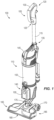
- Fig. 1 illustrates a cleaning system 100.
- the cleaning system 100 can be other types of cleaning systems (e.g., lightweight upright vacuums, hand-held vacuums, carpet cleaners, canister vacuums, bag vacuums, upright vacuums, etc.)
- the cleaning system 100 includes a handle portion 105 and a body portion 110.
- the handle portion 105 and the body portion 110 are connected via a spine 115.
- the handle portion 105 includes a first section 120 and a second section 125.
- the first section 120 may be oblique with respect to the second section 125 and includes a grip portion 130.
- the grip portion 130 is used by a user to grip and control the cleaning system 100.
- one or more user-controlled switches 135 are located near the spine 115 on the body portion 110. However, in other constructions, the one or more user-controlled switches 135 may be located on the grip portion 130. In yet other constructions, the one or more user-controlled switches 135 are located on the spine 115 or in other areas of the body portion 110. The one or more user-controlled switches 135 provide operational control of the cleaning system 100 to the user. In some constructions, the one or more user-controlled switches 135 are two-position switches, having for example, an on-position and an off-position.
- the second section 125 includes one or more indicators for providing indications to a user related to the operational mode of the cleaning system 100.
- the one or more indicators are light-emitting diodes (LEDs).
- the handle portion 105 may be removably coupled to the body portion 110.
- the handle portion 105 may be detachable from the body portion 110 providing a suction force or vacuum through at least a portion of the handle portion 105 as a wand, or may be removable for storage or transport purposes.
- the handle portion 105 is coupled and secured to the body portion 110 via friction only.
- the handle portion 105 is coupled and secured to the body portion 110 via a screw or other suitable fashionable device.
- the handle portion 105 further includes a plurality of electrical connectors located at an interface between the handle portion 105 and the body portion 110.
- the electrical connectors electrically connect the handle portion 105 to the body portion 110, so that electrical signals related to the operation of the cleaning system 100 can be sent from the handle portion 105 to the body portion 110 to control, for example, a motor/fan assembly and/or a brush-roll assembly.
- the body portion 110 includes a battery receptacle 140, a motor/fan assembly 145, and a refuse chamber 150.
- the body portion 110 can further include a cyclonic separator.
- the body portion 110 can further include a disposable bag for dirt collection.
- the battery receptacle 140 receives a battery pack 155.
- the battery receptacle 140 includes a plurality of electrical connectors for electrically connecting the battery pack 155 to the cleaning system 100.
- the motor/fan assembly 145 includes a suction motor 160 ( Fig. 2 ) and a rotor, such as an impeller or a fan, coupled to the suction motor 160.
- the suction motor 160 is a brushless direct-current (BLDC) motor operable at multiple speeds, for example, a high-speed and a low-speed.
- the suction motor 160 can be a variety of other types of motors, including but not limited to, a single speed motor, a variable speed motor, a brush DC motor, a stepper motor, a synchronous motor, or other DC or AC motors.
- the refuse chamber 150 is positioned below the motor/fan assembly 145, and is removably coupled to the cleaning system 100 (e.g., removably coupled to the spine 115, the body portion 110, the motor/fan assembly 145, etc.).
- the refuse chamber 150 and the motor/fan assembly 145 are removably coupled together, and form a single unit when coupled together. In such a construction, the single unit is then removably coupled to the spine 115 and/or body portion 110.
- the refuse chamber 150 is bagless and includes a latching mechanism which secures the refuse chamber 150 to the cleaning system 100.
- the refuse chamber 150 further includes an inlet for receiving refuse.
- the refuse chamber 150 includes the disposable bag for collecting refuse.
- a lower end of the body portion 110 includes an interface attaching the body portion 110 to a base portion 165.
- the base portion 165 includes a corresponding interface for attaching to the body portion 110.
- the handle portion 105 and the body portion 110 pivotally move about a first axis parallel to a cleaning surface (e.g., the ground). Pivotal movement about the first axis allows the handle portion 105 and the body portion 110 to be moved from a position approximately perpendicular to the base portion 165 to a position approximately parallel to the ground.
- the handle portion 105 and body portion 110 are able to be moved through an angle of between approximately 0.0° and approximately 90.0° with respect to the base portion 165.
- the handle portion 105 and body portion 110 are pivotable through larger or smaller angles.
- the handle portion 105 and body portion 110 are also pivotable along a second axis.
- the second axis is approximately perpendicular to the first axis and is approximately parallel to the handle portion 105 and body portion 110. Pivotal movement about the second axis provides additional control and maneuverability of the cleaning system 100.
- a pivot joint is employed to allow movement about the first axis and the second axis.
- a ball joint is employed rather than the pivot joint.
- the base portion 165 includes a first wheel 170, a second wheel 175, a suction inlet 180, and a brush-roll assembly 185.
- the first and second wheels 170, 175 are rotatably coupled to the base portion 165.
- the suction inlet 180 allows refuse to enter into the cleaning system 100.
- the suction inlet 180 further includes an aperture which allows larger objects to enter the suction inlet 180 without requiring the user to lift the cleaning system 100.
- the brush-roll assembly 185 includes a brush and a brush-roll motor 190 ( Fig. 2 ).
- the brush-roll motor 190 is a BLDC motor operable at multiple speeds, for example, a high-speed and a low-speed.
- the brush-roll motor 190 can be a variety of other types of motors, including but not limited to, a single speed motor, a variable speed motor, a brush DC motor, a stepper motor, a synchronous motor, or other DC or AC motors.
- Fig. 2 is a diagram illustrating electrical and electronic components of the cleaning system 100.
- the electrical and electronic components of the cleaning system 100 are contained within the battery pack 155, a main body housing 200, a motor/fan assembly housing 205, and a brush-roll assembly housing 210.
- the electrical and electronic components of the cleaning system 100 may be contained within more, less, or different housings.
- the battery pack 155 includes one or more battery cells 215.
- the battery cells 215 are rechargeable lithium-ion battery cells.
- the one or more battery cells 215 may have a chemistry other than lithium-ion, such as but not limited to, nickel cadmium, nickel metal-hydride, etc. Additionally or alternatively, the one or more battery cells 215 may be non-rechargeable battery cells.
- the one or more battery cells 215 may be electrically connected in a series-type connection, a parallel-type connection, or both a series and parallel type connection.
- the battery pack 155 further includes a battery controller 220.
- the battery controller 220 includes a processing unit (e.g., a microprocessor, a microcontroller, or another suitable programmable device) and a memory unit.
- the battery controller 220 is implemented partially or entirely on a semiconductor (e.g., a field-programmable gate array ["FPGA"] semiconductor) chip.
- the battery controller 220 senses/monitors a variety of characteristics of the battery cells 215, including but not limited to, voltage, current, capacity, resistance, temperature and number of cells. In some constructions, if any of the sensed/monitored characteristics of the battery cells 215 are out of a predetermined range, the battery controller 220 prohibits the battery pack 155 from outputting current.
- the battery pack 155 selectively couples to main body housing 200 via the battery receptacle 140.
- the battery pack 155 selectively couples to the battery receptacle 140 through the use of one or more latching mechanisms.
- the battery pack 155 electrically connects to the main body housing 200 through a plurality of terminals.
- the plurality of terminals include positive battery terminals 225a, 225b, negative battery terminals 230a, 230b, and data serial line, or communications, terminals 235a, 235b.
- the cleaning system receives power through the positive battery terminals 225a, 225b and is electrically grounded through the negative battery terminals 230a, 230b.
- the battery pack 155 outputs and/or receives data, or serial data, through the communications terminals 235a, 235b.
- the battery receptacle 140 is configured to receive either a first battery pack or a second battery pack. Further, the cleaning system 100 is configured to be powered by either the first battery pack or the second battery pack.
- the first battery pack has different characteristics than the second battery pack. For example, but not limited to, the first battery pack may have a first capacity (e.g., 2A-h), while the second battery pack may have a second capacity (e.g., 4A-h). The characteristics may further be any of, or any combination of, voltage, current, resistance, number of cells, battery identification code, etc.
- the first battery pack When releasably coupled to the battery receptacle 140, the first battery pack outputs a first type of data through the communications terminals 235a, 235b.
- the first type of data is identification data identifying the first battery pack, or data indicative of one or more characteristics of the first battery pack. Additionally, when releasably coupled to the battery receptacle 140, the second battery pack outputs a second type of data through the communications terminals 235a, 235b.
- the second type of data is identification data identifying the second battery pack, or data indicative of one or more characteristics of the second battery pack.
- the battery pack 155 as discussed herein can be either the first battery pack or the second battery pack.
- the main body housing 200 of the cleaning system 100 includes a switch board 240.
- the switch board 240 selectively controls power from the battery pack 155 to a variety of electrical components of the cleaning system 100, such as but not limited to electrical components of the motor/fan assembly housing 205 and the brush-roll assembly housing 210.
- the switch board 240 is operated by the one or more user-controlled switches 135.
- the one or more user-controlled switches 135 include a main power switch 245 and a brush-roll switch 250.
- the main power switch 245 provides power from the battery pack 155 to electrical components within the motor/fan assembly housing 205 and the brush-roll assembly housing 210, while the brush-roll switch 250 provides power from the battery pack 155 to electrical components within the brush-roll assembly housing 210.
- the switch board 240 may include more or less components.
- the switch board 240 may include one or more fuses, one or more positive temperature coefficient (PTO) devices, etc.
- the main body housing 200 further includes a light 255.
- the main power switch 245 selectively provides power from the battery pack 155 to the light 255. Upon receiving power, the light 255 illuminates.
- the light 255 is located on the base portion 165.
- the light 255 can be one of a light-emitting diode (LED) or an incandescent light bulb.
- the main body housing 200 electrically connects to the motor/fan assembly housing 205 via a plurality of electrical terminals, including motor/fan power terminals 260a, 260b, motor/fan ground terminals 265a, 265b, and motor/fan communication terminals 270a, 270b.
- the motor/fan assembly housing 205 includes a speed control module 275 connected to the suction motor 160.
- the speed control module 275 operates the suction motor 160 at a defined speed.
- the speed control module 275 is a controller that outputs a control signal to the suction motor 160.
- the control signal operates the suction motor 160 at the defined speed.
- the speed control module 275 outputs a first control signal to operate the suction motor 160 at a first speed, and outputs a second control signal to operates the suction motor 160 at a second speed.
- the control signal is a pulse-width modulated (PWM) signal having a voltage and a duty cycle (e.g., 10%, 25%, 50%, 75%, etc.).
- PWM pulse-width modulated
- the average voltage value of the PWM signal is output to the suction motor 160 in order to operate the suction motor 160.
- a PWM signal having a high average voltage drives the motor at a high motor speed.
- a PWM signal having a low average voltage drives the motor at a low motor speed.
- the speed control module 275 receives power through the motor/fan power terminals 260a, 260b and is grounded through motor/fan ground terminals 265a, 265b. The speed control module 275 further receives data through the motor/fan communication terminals 270a, 270b. In the illustrated construction, the data received through the motor/fan communication terminals 270a, 270b is from the battery controller 220 of the battery pack 155. In some constructions, the speed control module 275 receives data from the battery controller 220, determines a motor operating speed based on the received data, and outputs a control signal indicative of the motor operating speed to the suction motor 160. For example, the data may be a first type of data from the first battery pack or a second type of data from the second battery pack.
- the speed control module 275 interprets the received data and operates the suction motor 160 at a first speed when the first type of data is received (i.e., the first battery pack is connected) or at a second speed when the second type of data is received (i.e., the second battery pack is connected).
- the speed control module 275 receives a motor operating speed from the battery controller 220, and outputs a control signal indicative of the motor operating speed to the suction motor 160.
- the speed control module 275 may receive a first type of data related to a first operating speed or a second type of data related to a second operating speed.
- the speed control module 275 operates the suction motor 160 at the first operating speed (i.e., when the first battery pack is connected) or at the second operating speed (i.e., when the second battery pack is connected).
- the motor/fan assembly housing 205 selectively couples to the main body housing 200 via one or more latching mechanisms. In other constructions, the motor/fan assembly housing 205 is permanently affixed to the main body housing 200.
- the main body housing 200 electrically connects to the brush-roll assembly housing 210 via a plurality of electrical terminals.
- the plurality of terminals includes brush-roll power terminals 280a, 280b and brush-roll ground terminals 285a, 285b. In other constructions, there may further be brush-roll communication terminals.
- the brush-roll assembly housing 210 includes a switch 290 and the brush-roll motor 190.
- the switch 290 receives power through the brush-roll power terminals 280a, 280b and selectively provides power to the brush-roll motor 190.
- the brush-roll motor 190 rotates the brush.
- the brush-roll motor 190 is ground through the brush-roll ground terminals 285a, 285b.
- the switch 290 is activated when the cleaning system 100 is in an operation position, such as when the handle portion 105 and the body portion 110 are tilted downward along the first axis at an approximate angle of less than 90°. In such a construction, the switch 290 is deactivated when the cleaning system 100 is in an upright position, such as when the handle portion 105 and the body portion 110 are tilted upward along the first axis at an angle equal to approximately 90°.
- the brush-roll motor 190 is operated by the speed control module 275, or the control signal from the speed control module 275. In such a construction, the brush-roll motor 190 receives the control signal from the speed control module 275 through the brush-roll power terminals 280a, 280b. The brush-roll motor 190 operates at a speed (e.g., a first brush-roll-motor speed, a second brush-roll-motor speed, etc.) based on the control signal.
- a speed e.g., a first brush-roll-motor speed, a second brush-roll-motor speed, etc.
- Fig. 3 is a flow chart illustrating an operation 300 of the cleaning system 100. Although illustrated as occurring in a sequential order, it should be understood that the order of the steps discloses in operation 300 may vary. Furthermore, additional steps may be included in the operation 300 and not all of the steps may be required.
- the battery receptacle receives the battery pack 155 (Step 305).
- the cleaning system 100 is powered on (Step 310).
- the speed control module 275 received data from the battery pack 155 (Step 315).
- the speed control module 275 operates the suction motor 160 at a defined speed based on the received data (Step 320).
- Fig 4 is a flow chart illustrating a specific operation 400 of the cleaning system 100. Although illustrated as occurring in a sequential order, it should be understood that the order of the steps discloses in operation 400 may vary. Furthermore, additional steps may be included in the operation 400 and not all of the steps may be required.
- the battery receptacle 140 receives the first battery pack or the second battery pack (Step 405).
- the cleaning system 100 is powered on (Step 410).
- the speed control module 275 receives data from the battery pack 155 (Step 415).
- the speed control module 275 determines if the data is a first type of data (Step 420). If the received data is a first type of data, the speed control module 275 operates the suction motor 160 at a first speed (Step 425). If the received data is not a first type of data, and thus a second type of data, the speed control module 275 operates the suction motor 160 at a second speed (Step 430).
- the invention provides, among other things, a cleaning system configured to receive a battery pack and operate a suction motor based on the data received from the battery pack.
Claims (4)
- Procédé permettant de faire fonctionner un système de nettoyage (100), caractérisé en ce que le procédé comprend :la réception d'un premier bloc-batterie comportant un premier dispositif de commande de batterie ;la réception d'un premier signal indiquant une première capacité de batterie à partir du premier dispositif de commande de batterie ;la sortie d'un premier signal de commande sur la base de la réception du premier signal ;le fait de faire fonctionner un moteur (160) à une première vitesse sur la base du premier signal de commande, etle fait de faire fonctionner un second moteur (190) à la première vitesse sur la base du premier signal de commande, oula réception d'un second bloc-batterie comportant un second dispositif de commande de batterie ;la réception d'un second signal indiquant une seconde capacité de batterie à partir du second dispositif de commande de batterie ;la sortie d'un second signal de commande sur la base de la réception du second signal ;le fait de faire fonctionner le moteur (160) à une seconde vitesse sur la base du second signal de commande, etle fait de faire fonctionner le second moteur (190) à la seconde vitesse sur la base du second signal de commande.
- Procédé selon la revendication 1, dans lequel le moteur (160) entraîne une roue et/ou le second moteur (190) entraîne un rouleau à brosse.
- Système de nettoyage (100) comprenant :un moteur (160) ;un second moteur (190) ;une roue entraînée par le moteur (160) ;un réceptacle de batterie (140) conçu pour recevoir un premier bloc-batterie et le réceptacle de batterie (140) étant également conçu pour recevoir un second bloc-batterie ; et caractérisé en ce que le système de nettoyage comprend en outre :un dispositif de commande (275) configuré pourrecevoir un premier signal indiquant une première capacité de batterie à partir du premier bloc-batterie et d'un second signal indiquant une seconde capacité de batterie à partir du second bloc-batterie,faire fonctionner le moteur (160) à une vitesse définie, la vitesse définie étantune première vitesse sur la base du premier signal, etune seconde vitesse sur la base du second signal, etfaire fonctionner le second moteur (190) à une seconde vitesse définie, la seconde vitesse définie étantla première vitesse lorsque le dispositif de commande de moteur (275) reçoit le premier signal, etla seconde vitesse lorsque le dispositif de commande de moteur (275) reçoit le second signal.
- Système de nettoyage (100) selon la revendication 3, dans lequel le second moteur (190) entraîne un rouleau à brosse.
Applications Claiming Priority (2)
| Application Number | Priority Date | Filing Date | Title |
|---|---|---|---|
| US201361907725P | 2013-11-22 | 2013-11-22 | |
| PCT/US2014/066865 WO2015077588A1 (fr) | 2013-11-22 | 2014-11-21 | Système de nettoyage sans fil alimenté par batteries |
Publications (2)
| Publication Number | Publication Date |
|---|---|
| EP3071087A1 EP3071087A1 (fr) | 2016-09-28 |
| EP3071087B1 true EP3071087B1 (fr) | 2023-07-26 |
Family
ID=52103009
Family Applications (1)
| Application Number | Title | Priority Date | Filing Date |
|---|---|---|---|
| EP14812686.5A Active EP3071087B1 (fr) | 2013-11-22 | 2014-11-21 | Système de nettoyage sans fil alimenté par batteries |
Country Status (4)
| Country | Link |
|---|---|
| US (3) | US9456726B2 (fr) |
| EP (1) | EP3071087B1 (fr) |
| CN (1) | CN105744873B (fr) |
| WO (1) | WO2015077588A1 (fr) |
Families Citing this family (17)
| Publication number | Priority date | Publication date | Assignee | Title |
|---|---|---|---|---|
| JP5461221B2 (ja) | 2010-02-12 | 2014-04-02 | 株式会社マキタ | 複数のバッテリパックを電源とする電動工具 |
| US10758101B2 (en) * | 2017-06-12 | 2020-09-01 | Emerson Electric Co. | Upright vacuum cleaner with battery support plate |
| CN107837048B (zh) * | 2017-10-14 | 2020-09-01 | 金日清洁设备(苏州)有限公司 | 无绳洗地机 |
| CN109691931B (zh) | 2017-10-20 | 2022-04-01 | 创科电动工具科技有限公司 | 真空吸尘器和控制真空吸尘器刷子的电机的方法 |
| JP7122619B2 (ja) * | 2017-10-31 | 2022-08-22 | パナソニックIpマネジメント株式会社 | 捕集システム、及び捕集機 |
| US11218009B2 (en) * | 2018-04-18 | 2022-01-04 | Milwaukee Electric Tool Corporation | Tool circuitry for series-type connected battery packs |
| US10483898B1 (en) * | 2018-04-30 | 2019-11-19 | Regal Beloit America, Inc. | Motor control system for electric motor and method of use |
| DE102018214149A1 (de) * | 2018-08-22 | 2020-02-27 | BSH Hausgeräte GmbH | Staubsauger |
| US20200187741A1 (en) * | 2018-12-18 | 2020-06-18 | Bissell Inc. | Surface cleaning apparatus and communication method |
| DE102019104637A1 (de) * | 2019-02-25 | 2020-08-27 | Miele & Cie. Kg | Haushaltsgerät, umfassend eine Energiespeicheraufnahme zur Aufnahme eines wechselbaren Energiespeichers, und Verfahren für dessen Betrieb |
| GB2582349B (en) * | 2019-03-20 | 2021-09-15 | Dyson Technology Ltd | Vacuum cleaner |
| JP7341817B2 (ja) | 2019-09-20 | 2023-09-11 | 株式会社マキタ | 電動作業機 |
| EP3806273A1 (fr) | 2019-10-11 | 2021-04-14 | Black & Decker Inc. | Outil électrique recevant des blocs-batteries de différentes capacités |
| USD986521S1 (en) * | 2020-08-06 | 2023-05-16 | Jiangsu Midea Cleaning Appliances Co., Ltd. | Vacuum cleaner |
| US11641995B2 (en) * | 2021-04-21 | 2023-05-09 | Omachron Intellectual Property Inc. | Surface cleaning apparatus |
| USD1017156S1 (en) | 2022-05-09 | 2024-03-05 | Dupray Ventures Inc. | Cleaner |
| CN114983274A (zh) * | 2022-06-06 | 2022-09-02 | 深圳银星智能集团股份有限公司 | 清洁机器人及清洁系统 |
Family Cites Families (86)
| Publication number | Priority date | Publication date | Assignee | Title |
|---|---|---|---|---|
| GB2225219B (en) | 1988-10-19 | 1992-08-26 | Hoover Plc | Suction cleaner |
| US4920606A (en) | 1989-01-09 | 1990-05-01 | Black & Decker, Inc. | Electrical power circuit for a vacuum cleaner |
| EP0479609A3 (en) | 1990-10-05 | 1993-01-20 | Hitachi, Ltd. | Vacuum cleaner and control method thereof |
| US5222276A (en) | 1992-01-10 | 1993-06-29 | Ryobi Motor Products Corp. | Vacuum cleaner for on floor and off floor suction cleaning |
| US5363534A (en) | 1992-06-19 | 1994-11-15 | U.S. Philips Corporation | Vacuum cleaner and suction tube for use with a vacuum cleaner |
| DE4327070C1 (de) | 1993-08-12 | 1995-04-06 | Gerhard Kurz | Vorrichtung zur Regelung der Leistungsaufnahme eines Staubsaugers |
| DE4433181C2 (de) | 1994-09-17 | 1999-06-17 | Miele & Cie | Verfahren zur Vermeidung von Überschwingungen bei der automatischen Saugleistungsregelung eines Staubsaugers |
| JPH10314078A (ja) * | 1997-05-15 | 1998-12-02 | Fuji Heavy Ind Ltd | 清掃装置用制御装置 |
| JP2001501860A (ja) | 1997-08-11 | 2001-02-13 | コーニンクレッカ フィリップス エレクトロニクス エヌ ヴィ | 可制御電気駆動手段が設けられた吸引ノズルを有する真空掃除機 |
| US6226830B1 (en) | 1997-08-20 | 2001-05-08 | Philips Electronics North America Corp. | Vacuum cleaner with obstacle avoidance |
| DE19902130A1 (de) | 1998-01-23 | 1999-09-23 | Kwang Ju Electronics Co Ltd | Fernsteuervorrichtung eines Staubsaugers |
| DE19813434A1 (de) | 1998-03-27 | 1999-09-30 | Proair Geraetebau Gmbh | Naßsauger |
| GB2344746A (en) | 1998-12-18 | 2000-06-21 | Notetry Ltd | Vacuum cleaner wherein an alternative air inlet is selected by moving the separating apparatus |
| US6374453B1 (en) | 1999-09-02 | 2002-04-23 | Young S. Kim | Convertible vacuum cleaner |
| CA2306531C (fr) | 1999-10-15 | 2011-07-12 | Wayne Ernest Conrad | Methode et appareil de transmission de puissance a un systeme mecanique ou electrique |
| US6457205B1 (en) * | 2000-05-24 | 2002-10-01 | Fantom Technologies Inc. | Vacuum cleaner having a plurality of power modes |
| CA2386877C (fr) | 2001-05-21 | 2006-08-29 | The Hoover Company | Dispositif et methode de nettoyage d'une surface |
| TW579289B (en) | 2001-05-23 | 2004-03-11 | Toshiba Tec Kk | Vacuum cleaner |
| JP4097182B2 (ja) * | 2001-12-27 | 2008-06-11 | パナソニックEvエナジー株式会社 | 二次電池の分極電圧推定方法、二次電池の残存容量推定方法および装置、並びに電池パックシステム |
| JP2004135835A (ja) | 2002-10-17 | 2004-05-13 | Toshiba Tec Corp | 電気掃除機 |
| US7000285B2 (en) | 2003-01-09 | 2006-02-21 | Royal Appliance Mfg. Co. | Control circuitry for enabling drive system for vacuum cleaner |
| FR2852811B1 (fr) | 2003-03-27 | 2005-06-24 | Nielsen Innovation | Aspirateur autonome bimoteur |
| WO2004096000A2 (fr) | 2003-04-26 | 2004-11-11 | Panasonic Corporation Of North America | Poignee de manipulation tournante d'aspirateur |
| CA2471407A1 (fr) | 2003-06-17 | 2004-12-17 | Matsushita Electric Corporation Of America | Aspirateur vertical equipe d'un tuyau souple et d'un tube electrifies |
| DE10327909A1 (de) | 2003-06-21 | 2005-01-05 | Vorwerk & Co. Interholding Gmbh | Verfahren zur Schaltung eines Vorsatzgerätes sowie Staubsauger mit einem Vorsatzgerät |
| US7712182B2 (en) * | 2003-07-25 | 2010-05-11 | Milwaukee Electric Tool Corporation | Air flow-producing device, such as a vacuum cleaner or a blower |
| US20050022338A1 (en) | 2003-07-28 | 2005-02-03 | Muhlenkamp Eric E. | Electrified extension hose for vacuum cleaner |
| US7237298B2 (en) * | 2003-09-19 | 2007-07-03 | Royal Appliance Mfg. Co. | Sensors and associated methods for controlling a vacuum cleaner |
| US7725223B2 (en) | 2003-09-30 | 2010-05-25 | Techtronic Floor Care Technology Limited | Control arrangement for a propulsion unit for a self-propelled floor care appliance |
| US20050071056A1 (en) | 2003-09-30 | 2005-03-31 | Tondra Aaron P. | Control arrangement for a propulsion unit for a self-propelled floor care appliance |
| JP2005132190A (ja) * | 2003-10-29 | 2005-05-26 | Denso Corp | 車両用電源システム |
| KR100539757B1 (ko) | 2003-12-24 | 2006-01-10 | 엘지전자 주식회사 | 업라이트형 진공청소기의 파워 스위치 장치 |
| US20050189915A1 (en) * | 2004-02-18 | 2005-09-01 | Quartex, Inc. | Battery arrangement |
| AU2005218490B2 (en) * | 2004-03-02 | 2010-04-01 | Bissell Inc. | Vacuum cleaner with detachable cyclonic vacuum module |
| US7688028B2 (en) * | 2004-10-18 | 2010-03-30 | Black & Decker Inc. | Cordless power system |
| WO2006046036A2 (fr) | 2004-10-25 | 2006-05-04 | Jacm Limited | Aspirateur |
| US7332881B2 (en) * | 2004-10-28 | 2008-02-19 | Textron Inc. | AC drive system for electrically operated vehicle |
| US7870637B2 (en) | 2004-12-10 | 2011-01-18 | Techtronic Floor Care Technology Limited | Stacked tank arrangement for a cleaning apparatus |
| GB2434523B (en) | 2005-10-12 | 2011-03-23 | Benjamin Edginton | An upright cleaner that is selectable as an air recycling cleaner or a vacuum cleaner |
| US7690078B2 (en) | 2005-11-02 | 2010-04-06 | The Scott Fetzer Company | Vacuum cleaner with removable cleaning attachment |
| US20070094839A1 (en) | 2005-11-03 | 2007-05-03 | The Scott Fetzer Company | Cleaning apparatus with removable handle |
| US7587786B2 (en) | 2005-11-03 | 2009-09-15 | The Scott Fetzer Company | Vacuum cleaner with removable handle |
| ITMO20050321A1 (it) | 2005-11-29 | 2007-05-30 | Massimiliano Pineschi | Elettrodomestico portatile |
| US20070136979A1 (en) | 2005-12-21 | 2007-06-21 | The Scott Fetzer Company | Vacuum cleaner with electronic controller |
| US7694383B2 (en) | 2006-01-06 | 2010-04-13 | The Scott Fetzer Company | Upright vacuum cleaner with removable power head |
| GB0601278D0 (en) | 2006-01-23 | 2006-03-01 | Creative Consultancy Ltd | Floor cleaning apparatus |
| US7328479B2 (en) | 2006-04-13 | 2008-02-12 | Electrolux Home Care Products Ltd. | Lighting apparatus for a vacuum cleaner |
| GB2440717A (en) | 2006-08-08 | 2008-02-13 | Dyson Technology Ltd | Circuit breaker system for a vacuum cleaner |
| EP2062517B1 (fr) | 2006-09-11 | 2019-12-11 | Panasonic Corporation | Appareil de nettoyage électrique |
| US7479754B2 (en) * | 2006-10-17 | 2009-01-20 | Desa Ip Llc | Hybrid electric lawnmower |
| US8732896B2 (en) * | 2006-10-17 | 2014-05-27 | Mtd Products Inc | Hybrid electric cleaning device |
| US7573239B2 (en) * | 2006-12-29 | 2009-08-11 | Honeywell International Inc. | Circuit for monitoring batteries in a parallel configuration while under load |
| KR20080092063A (ko) | 2007-04-11 | 2008-10-15 | 삼성광주전자 주식회사 | 진공청소기용 먼지감지 유닛 |
| US8172932B2 (en) | 2007-04-11 | 2012-05-08 | Samsung Electronics Co., Ltd. | Connecting tube having dust sensing function for use in vacuum cleaner |
| DE102008000704A1 (de) | 2007-04-24 | 2008-10-30 | Robert Bosch Gmbh | Elektrowerkzeug und Geräteschalter für ein Elektrowerkzeug |
| JP4640389B2 (ja) * | 2007-07-30 | 2011-03-02 | トヨタ自動車株式会社 | ポンプ制御装置およびブレーキ制御装置 |
| DE102007040957A1 (de) | 2007-08-30 | 2009-03-05 | Miele & Cie. Kg | Upright-Staubsauger |
| DE102007040952A1 (de) * | 2007-08-30 | 2009-03-05 | Miele & Cie. Kg | Upright-Staubsauger |
| US7825615B2 (en) | 2007-10-16 | 2010-11-02 | Glj, Llc | Intelligent motorized appliances with multiple power sources |
| JP5269811B2 (ja) * | 2007-12-26 | 2013-08-21 | 住友重機械工業株式会社 | ハイブリッド型建設機械及びハイブリッド型建設機械の制御方法 |
| US7979953B2 (en) | 2008-01-16 | 2011-07-19 | Samsung Gwangju Electronics Co., Ltd. | Vacuum cleaner |
| US8607405B2 (en) * | 2008-03-14 | 2013-12-17 | Techtronic Floor Care Technology Limited | Battery powered cordless cleaning system |
| EP2113182B1 (fr) | 2008-05-02 | 2011-07-06 | Black & Decker, Inc. | Système de commande d'aspirateur |
| CN101714647B (zh) | 2008-10-08 | 2012-11-28 | 株式会社牧田 | 电动工具用蓄电池匣以及电动工具 |
| JP4947045B2 (ja) * | 2008-12-19 | 2012-06-06 | トヨタ自動車株式会社 | 冷却装置およびこれを搭載する車両 |
| US8326502B2 (en) * | 2008-12-31 | 2012-12-04 | Mark Snyder | Electric vehicle control |
| US8427087B2 (en) * | 2009-01-29 | 2013-04-23 | Toyota Jidosha Kabushiki Kaisha | Control device for AC motor |
| JP5149826B2 (ja) * | 2009-01-29 | 2013-02-20 | 住友重機械工業株式会社 | ハイブリッド式作業機械及びサーボ制御システム |
| GB2469140B (en) | 2009-04-04 | 2013-12-11 | Dyson Technology Ltd | Control of an electric machine |
| GB2508117B (en) * | 2009-04-04 | 2014-10-29 | Dyson Technology Ltd | High-speed electric system |
| CN102802488A (zh) | 2009-04-30 | 2012-11-28 | 伊莱克斯公司 | 真空清洁器和用于控制电动马达的方法 |
| TWI394344B (zh) * | 2009-07-07 | 2013-04-21 | Wistron Corp | 可攜式電腦系統及相關電源供應裝置與充電方法 |
| JP5461221B2 (ja) * | 2010-02-12 | 2014-04-02 | 株式会社マキタ | 複数のバッテリパックを電源とする電動工具 |
| JP5476177B2 (ja) | 2010-03-26 | 2014-04-23 | パナソニック株式会社 | 電動工具 |
| EP2377444A1 (fr) | 2010-04-16 | 2011-10-19 | Miele & Cie. KG | Aspirateur avec un dispositif de régulation du ventilateur |
| US8595893B2 (en) | 2010-04-30 | 2013-12-03 | Techtronic Floor Care Technology Limited | Upright vacuum with an automated diverter valve |
| US9007002B2 (en) * | 2010-06-15 | 2015-04-14 | Ihi Corporation | Device and method for power-saving driving of device having same load pattern |
| EP2468165B1 (fr) | 2010-12-21 | 2016-05-25 | Miele & Cie. KG | Aspirateur et procédé destiné au fonctionnement de l'aspirateur |
| DK2672870T3 (en) * | 2011-02-11 | 2015-03-02 | Kaercher Gmbh & Co Kg Alfred | Process for cleaning a filter in a vacuum cleaner and vacuum cleaner for carrying out the process |
| GB201106953D0 (en) | 2011-04-21 | 2011-06-01 | Numatic Int Ltd | Mobile electric appliance |
| US20120317749A1 (en) | 2011-06-17 | 2012-12-20 | Spiggle Anthony E | Floor care apparatus equipped with brush assembly |
| JP5937418B2 (ja) * | 2012-05-01 | 2016-06-22 | 株式会社マキタ | 流体装置 |
| KR102015315B1 (ko) * | 2012-10-09 | 2019-10-21 | 삼성전자주식회사 | 청소 로봇 및 그 제어 방법 |
| WO2014083596A1 (fr) * | 2012-11-30 | 2014-06-05 | トヨタ自動車株式会社 | Dispositif et procédé de contrôle de la génération d'énergie dans un générateur |
| US9174525B2 (en) * | 2013-02-25 | 2015-11-03 | Fairfield Manufacturing Company, Inc. | Hybrid electric vehicle |
| MX347885B (es) * | 2014-05-16 | 2017-05-16 | Techtronic Power Tools Tech Ltd | Paquete de multi-baterias de herramientas electricas. |
-
2014
- 2014-11-21 EP EP14812686.5A patent/EP3071087B1/fr active Active
- 2014-11-21 WO PCT/US2014/066865 patent/WO2015077588A1/fr active Application Filing
- 2014-11-21 US US14/550,079 patent/US9456726B2/en active Active
- 2014-11-21 CN CN201480063278.1A patent/CN105744873B/zh active Active
-
2016
- 2016-09-12 US US15/262,070 patent/US9844310B2/en active Active
-
2017
- 2017-12-18 US US15/844,782 patent/US10231590B2/en active Active
Also Published As
| Publication number | Publication date |
|---|---|
| WO2015077588A1 (fr) | 2015-05-28 |
| EP3071087A1 (fr) | 2016-09-28 |
| US9456726B2 (en) | 2016-10-04 |
| US20180103815A1 (en) | 2018-04-19 |
| US9844310B2 (en) | 2017-12-19 |
| US20150145444A1 (en) | 2015-05-28 |
| CN105744873B (zh) | 2018-09-04 |
| US20160374525A1 (en) | 2016-12-29 |
| US10231590B2 (en) | 2019-03-19 |
| CN105744873A (zh) | 2016-07-06 |
Similar Documents
| Publication | Publication Date | Title |
|---|---|---|
| EP3071087B1 (fr) | Système de nettoyage sans fil alimenté par batteries | |
| CN105025770B (zh) | 电池驱动的无线清洁系统 | |
| US11510540B2 (en) | Vacuum cleaner and system operable with AC and DC power sources | |
| CN101817106B (zh) | 蓄电池驱动的手操纵式工作器械 | |
| JP4021625B2 (ja) | 集塵機及び電動工具 | |
| WO2014119160A1 (fr) | Collecteur de poussière | |
| CN109528080B (zh) | 电池供电的无绳清洁系统 | |
| CN101817177A (zh) | 带有加速杆的蓄电池驱动的手操纵式工作器械 | |
| EP4190140A1 (fr) | Dispositif de déplacement extérieur | |
| JP2001179705A (ja) | 集じん機 | |
| WO2021141816A1 (fr) | Ensemble aspirateur à partage d'énergie | |
| US20220369883A1 (en) | Power sharing vacuum cleaner assembly | |
| US11794324B2 (en) | Dust collecting system | |
| US20200306907A1 (en) | Dust collecting system | |
| JP2008079523A (ja) | 庭木バリカン | |
| EP1806831A2 (fr) | Appareil à débit d'air portable avec alimentation électrique double | |
| EP3525650B1 (fr) | Appareil de nettoyage de surfaces | |
| KR20170021113A (ko) | 코드리스 분리형 청소기 | |
| US20220123572A1 (en) | Battery-operated device including an electromechanical interface for an interchangeable drive unit | |
| WO2020131553A1 (fr) | Système et procédé pour fournir de l'énergie à un moteur | |
| CN118055721A (zh) | 能够与回收装置连接的吸尘器 | |
| JPS62298329A (ja) | 充電式電気掃除機 |
Legal Events
| Date | Code | Title | Description |
|---|---|---|---|
| PUAI | Public reference made under article 153(3) epc to a published international application that has entered the european phase |
Free format text: ORIGINAL CODE: 0009012 |
|
| 17P | Request for examination filed |
Effective date: 20160608 |
|
| AK | Designated contracting states |
Kind code of ref document: A1 Designated state(s): AL AT BE BG CH CY CZ DE DK EE ES FI FR GB GR HR HU IE IS IT LI LT LU LV MC MK MT NL NO PL PT RO RS SE SI SK SM TR |
|
| AX | Request for extension of the european patent |
Extension state: BA ME |
|
| DAX | Request for extension of the european patent (deleted) | ||
| STAA | Information on the status of an ep patent application or granted ep patent |
Free format text: STATUS: EXAMINATION IS IN PROGRESS |
|
| 17Q | First examination report despatched |
Effective date: 20200625 |
|
| STAA | Information on the status of an ep patent application or granted ep patent |
Free format text: STATUS: EXAMINATION IS IN PROGRESS |
|
| STAA | Information on the status of an ep patent application or granted ep patent |
Free format text: STATUS: EXAMINATION IS IN PROGRESS |
|
| GRAP | Despatch of communication of intention to grant a patent |
Free format text: ORIGINAL CODE: EPIDOSNIGR1 |
|
| STAA | Information on the status of an ep patent application or granted ep patent |
Free format text: STATUS: GRANT OF PATENT IS INTENDED |
|
| INTG | Intention to grant announced |
Effective date: 20230313 |
|
| GRAS | Grant fee paid |
Free format text: ORIGINAL CODE: EPIDOSNIGR3 |
|
| GRAA | (expected) grant |
Free format text: ORIGINAL CODE: 0009210 |
|
| STAA | Information on the status of an ep patent application or granted ep patent |
Free format text: STATUS: THE PATENT HAS BEEN GRANTED |
|
| AK | Designated contracting states |
Kind code of ref document: B1 Designated state(s): AL AT BE BG CH CY CZ DE DK EE ES FI FR GB GR HR HU IE IS IT LI LT LU LV MC MK MT NL NO PL PT RO RS SE SI SK SM TR |
|
| REG | Reference to a national code |
Ref country code: CH Ref legal event code: EP |
|
| REG | Reference to a national code |
Ref country code: DE Ref legal event code: R096 Ref document number: 602014087764 Country of ref document: DE |
|
| REG | Reference to a national code |
Ref country code: IE Ref legal event code: FG4D |
|
| REG | Reference to a national code |
Ref country code: LT Ref legal event code: MG9D |
|
| REG | Reference to a national code |
Ref country code: NL Ref legal event code: MP Effective date: 20230726 |
|
| REG | Reference to a national code |
Ref country code: AT Ref legal event code: MK05 Ref document number: 1590934 Country of ref document: AT Kind code of ref document: T Effective date: 20230726 |
|
| PG25 | Lapsed in a contracting state [announced via postgrant information from national office to epo] |
Ref country code: NL Free format text: LAPSE BECAUSE OF FAILURE TO SUBMIT A TRANSLATION OF THE DESCRIPTION OR TO PAY THE FEE WITHIN THE PRESCRIBED TIME-LIMIT Effective date: 20230726 |
|
| PG25 | Lapsed in a contracting state [announced via postgrant information from national office to epo] |
Ref country code: GR Free format text: LAPSE BECAUSE OF FAILURE TO SUBMIT A TRANSLATION OF THE DESCRIPTION OR TO PAY THE FEE WITHIN THE PRESCRIBED TIME-LIMIT Effective date: 20231027 |
|
| PGFP | Annual fee paid to national office [announced via postgrant information from national office to epo] |
Ref country code: GB Payment date: 20231127 Year of fee payment: 10 |
|
| PG25 | Lapsed in a contracting state [announced via postgrant information from national office to epo] |
Ref country code: IS Free format text: LAPSE BECAUSE OF FAILURE TO SUBMIT A TRANSLATION OF THE DESCRIPTION OR TO PAY THE FEE WITHIN THE PRESCRIBED TIME-LIMIT Effective date: 20231126 |
|
| PG25 | Lapsed in a contracting state [announced via postgrant information from national office to epo] |
Ref country code: SE Free format text: LAPSE BECAUSE OF FAILURE TO SUBMIT A TRANSLATION OF THE DESCRIPTION OR TO PAY THE FEE WITHIN THE PRESCRIBED TIME-LIMIT Effective date: 20230726 Ref country code: RS Free format text: LAPSE BECAUSE OF FAILURE TO SUBMIT A TRANSLATION OF THE DESCRIPTION OR TO PAY THE FEE WITHIN THE PRESCRIBED TIME-LIMIT Effective date: 20230726 Ref country code: PT Free format text: LAPSE BECAUSE OF FAILURE TO SUBMIT A TRANSLATION OF THE DESCRIPTION OR TO PAY THE FEE WITHIN THE PRESCRIBED TIME-LIMIT Effective date: 20231127 Ref country code: NO Free format text: LAPSE BECAUSE OF FAILURE TO SUBMIT A TRANSLATION OF THE DESCRIPTION OR TO PAY THE FEE WITHIN THE PRESCRIBED TIME-LIMIT Effective date: 20231026 Ref country code: LV Free format text: LAPSE BECAUSE OF FAILURE TO SUBMIT A TRANSLATION OF THE DESCRIPTION OR TO PAY THE FEE WITHIN THE PRESCRIBED TIME-LIMIT Effective date: 20230726 Ref country code: LT Free format text: LAPSE BECAUSE OF FAILURE TO SUBMIT A TRANSLATION OF THE DESCRIPTION OR TO PAY THE FEE WITHIN THE PRESCRIBED TIME-LIMIT Effective date: 20230726 Ref country code: IS Free format text: LAPSE BECAUSE OF FAILURE TO SUBMIT A TRANSLATION OF THE DESCRIPTION OR TO PAY THE FEE WITHIN THE PRESCRIBED TIME-LIMIT Effective date: 20231126 Ref country code: HR Free format text: LAPSE BECAUSE OF FAILURE TO SUBMIT A TRANSLATION OF THE DESCRIPTION OR TO PAY THE FEE WITHIN THE PRESCRIBED TIME-LIMIT Effective date: 20230726 Ref country code: GR Free format text: LAPSE BECAUSE OF FAILURE TO SUBMIT A TRANSLATION OF THE DESCRIPTION OR TO PAY THE FEE WITHIN THE PRESCRIBED TIME-LIMIT Effective date: 20231027 Ref country code: FI Free format text: LAPSE BECAUSE OF FAILURE TO SUBMIT A TRANSLATION OF THE DESCRIPTION OR TO PAY THE FEE WITHIN THE PRESCRIBED TIME-LIMIT Effective date: 20230726 Ref country code: AT Free format text: LAPSE BECAUSE OF FAILURE TO SUBMIT A TRANSLATION OF THE DESCRIPTION OR TO PAY THE FEE WITHIN THE PRESCRIBED TIME-LIMIT Effective date: 20230726 |
|
| PG25 | Lapsed in a contracting state [announced via postgrant information from national office to epo] |
Ref country code: PL Free format text: LAPSE BECAUSE OF FAILURE TO SUBMIT A TRANSLATION OF THE DESCRIPTION OR TO PAY THE FEE WITHIN THE PRESCRIBED TIME-LIMIT Effective date: 20230726 |
|
| PG25 | Lapsed in a contracting state [announced via postgrant information from national office to epo] |
Ref country code: ES Free format text: LAPSE BECAUSE OF FAILURE TO SUBMIT A TRANSLATION OF THE DESCRIPTION OR TO PAY THE FEE WITHIN THE PRESCRIBED TIME-LIMIT Effective date: 20230726 |
|
| PG25 | Lapsed in a contracting state [announced via postgrant information from national office to epo] |
Ref country code: SM Free format text: LAPSE BECAUSE OF FAILURE TO SUBMIT A TRANSLATION OF THE DESCRIPTION OR TO PAY THE FEE WITHIN THE PRESCRIBED TIME-LIMIT Effective date: 20230726 Ref country code: RO Free format text: LAPSE BECAUSE OF FAILURE TO SUBMIT A TRANSLATION OF THE DESCRIPTION OR TO PAY THE FEE WITHIN THE PRESCRIBED TIME-LIMIT Effective date: 20230726 Ref country code: ES Free format text: LAPSE BECAUSE OF FAILURE TO SUBMIT A TRANSLATION OF THE DESCRIPTION OR TO PAY THE FEE WITHIN THE PRESCRIBED TIME-LIMIT Effective date: 20230726 Ref country code: EE Free format text: LAPSE BECAUSE OF FAILURE TO SUBMIT A TRANSLATION OF THE DESCRIPTION OR TO PAY THE FEE WITHIN THE PRESCRIBED TIME-LIMIT Effective date: 20230726 Ref country code: DK Free format text: LAPSE BECAUSE OF FAILURE TO SUBMIT A TRANSLATION OF THE DESCRIPTION OR TO PAY THE FEE WITHIN THE PRESCRIBED TIME-LIMIT Effective date: 20230726 Ref country code: CZ Free format text: LAPSE BECAUSE OF FAILURE TO SUBMIT A TRANSLATION OF THE DESCRIPTION OR TO PAY THE FEE WITHIN THE PRESCRIBED TIME-LIMIT Effective date: 20230726 Ref country code: SK Free format text: LAPSE BECAUSE OF FAILURE TO SUBMIT A TRANSLATION OF THE DESCRIPTION OR TO PAY THE FEE WITHIN THE PRESCRIBED TIME-LIMIT Effective date: 20230726 |