EP3069005B1 - Kraftstoffeinspritzer - Google Patents
Kraftstoffeinspritzer Download PDFInfo
- Publication number
- EP3069005B1 EP3069005B1 EP14802330.2A EP14802330A EP3069005B1 EP 3069005 B1 EP3069005 B1 EP 3069005B1 EP 14802330 A EP14802330 A EP 14802330A EP 3069005 B1 EP3069005 B1 EP 3069005B1
- Authority
- EP
- European Patent Office
- Prior art keywords
- injector
- contact
- injection needle
- injection
- electrical resistivity
- Prior art date
- Legal status (The legal status is an assumption and is not a legal conclusion. Google has not performed a legal analysis and makes no representation as to the accuracy of the status listed.)
- Active
Links
Images
Classifications
-
- F—MECHANICAL ENGINEERING; LIGHTING; HEATING; WEAPONS; BLASTING
- F02—COMBUSTION ENGINES; HOT-GAS OR COMBUSTION-PRODUCT ENGINE PLANTS
- F02M—SUPPLYING COMBUSTION ENGINES IN GENERAL WITH COMBUSTIBLE MIXTURES OR CONSTITUENTS THEREOF
- F02M51/00—Fuel-injection apparatus characterised by being operated electrically
- F02M51/06—Injectors peculiar thereto with means directly operating the valve needle
- F02M51/061—Injectors peculiar thereto with means directly operating the valve needle using electromagnetic operating means
- F02M51/0625—Injectors peculiar thereto with means directly operating the valve needle using electromagnetic operating means characterised by arrangement of mobile armatures
- F02M51/0635—Injectors peculiar thereto with means directly operating the valve needle using electromagnetic operating means characterised by arrangement of mobile armatures having a plate-shaped or undulated armature not entering the winding
- F02M51/0642—Injectors peculiar thereto with means directly operating the valve needle using electromagnetic operating means characterised by arrangement of mobile armatures having a plate-shaped or undulated armature not entering the winding the armature having a valve attached thereto
- F02M51/0653—Injectors peculiar thereto with means directly operating the valve needle using electromagnetic operating means characterised by arrangement of mobile armatures having a plate-shaped or undulated armature not entering the winding the armature having a valve attached thereto the valve being an elongated body, e.g. a needle valve
-
- F—MECHANICAL ENGINEERING; LIGHTING; HEATING; WEAPONS; BLASTING
- F02—COMBUSTION ENGINES; HOT-GAS OR COMBUSTION-PRODUCT ENGINE PLANTS
- F02M—SUPPLYING COMBUSTION ENGINES IN GENERAL WITH COMBUSTIBLE MIXTURES OR CONSTITUENTS THEREOF
- F02M57/00—Fuel-injectors combined or associated with other devices
- F02M57/005—Fuel-injectors combined or associated with other devices the devices being sensors
-
- F—MECHANICAL ENGINEERING; LIGHTING; HEATING; WEAPONS; BLASTING
- F02—COMBUSTION ENGINES; HOT-GAS OR COMBUSTION-PRODUCT ENGINE PLANTS
- F02M—SUPPLYING COMBUSTION ENGINES IN GENERAL WITH COMBUSTIBLE MIXTURES OR CONSTITUENTS THEREOF
- F02M61/00—Fuel-injectors not provided for in groups F02M39/00 - F02M57/00 or F02M67/00
- F02M61/16—Details not provided for in, or of interest apart from, the apparatus of groups F02M61/02 - F02M61/14
- F02M61/20—Closing valves mechanically, e.g. arrangements of springs or weights or permanent magnets; Damping of valve lift
-
- G—PHYSICS
- G01—MEASURING; TESTING
- G01D—MEASURING NOT SPECIALLY ADAPTED FOR A SPECIFIC VARIABLE; ARRANGEMENTS FOR MEASURING TWO OR MORE VARIABLES NOT COVERED IN A SINGLE OTHER SUBCLASS; TARIFF METERING APPARATUS; MEASURING OR TESTING NOT OTHERWISE PROVIDED FOR
- G01D5/00—Mechanical means for transferring the output of a sensing member; Means for converting the output of a sensing member to another variable where the form or nature of the sensing member does not constrain the means for converting; Transducers not specially adapted for a specific variable
- G01D5/12—Mechanical means for transferring the output of a sensing member; Means for converting the output of a sensing member to another variable where the form or nature of the sensing member does not constrain the means for converting; Transducers not specially adapted for a specific variable using electric or magnetic means
- G01D5/14—Mechanical means for transferring the output of a sensing member; Means for converting the output of a sensing member to another variable where the form or nature of the sensing member does not constrain the means for converting; Transducers not specially adapted for a specific variable using electric or magnetic means influencing the magnitude of a current or voltage
- G01D5/16—Mechanical means for transferring the output of a sensing member; Means for converting the output of a sensing member to another variable where the form or nature of the sensing member does not constrain the means for converting; Transducers not specially adapted for a specific variable using electric or magnetic means influencing the magnitude of a current or voltage by varying resistance
- G01D5/165—Mechanical means for transferring the output of a sensing member; Means for converting the output of a sensing member to another variable where the form or nature of the sensing member does not constrain the means for converting; Transducers not specially adapted for a specific variable using electric or magnetic means influencing the magnitude of a current or voltage by varying resistance by relative movement of a point of contact or actuation and a resistive track
- G01D5/1655—Mechanical means for transferring the output of a sensing member; Means for converting the output of a sensing member to another variable where the form or nature of the sensing member does not constrain the means for converting; Transducers not specially adapted for a specific variable using electric or magnetic means influencing the magnitude of a current or voltage by varying resistance by relative movement of a point of contact or actuation and a resistive track more than one point of contact or actuation on one or more tracks
-
- F—MECHANICAL ENGINEERING; LIGHTING; HEATING; WEAPONS; BLASTING
- F02—COMBUSTION ENGINES; HOT-GAS OR COMBUSTION-PRODUCT ENGINE PLANTS
- F02M—SUPPLYING COMBUSTION ENGINES IN GENERAL WITH COMBUSTIBLE MIXTURES OR CONSTITUENTS THEREOF
- F02M2200/00—Details of fuel-injection apparatus, not otherwise provided for
- F02M2200/24—Fuel-injection apparatus with sensors
- F02M2200/245—Position sensors, e.g. Hall sensors
Definitions
- the present invention relates to a fuel injector and more particularly to an arrangement allowing a closed-loop control of an injection system.
- the present invention aims to overcome the drawbacks of existing solutions by providing electrical supervision of the injector reflecting the movements of the injection needle of the injector.
- a fuel injector includes fixed metal components, including an injector body, a solenoid actuator having a control valve stem holding spring, a control valve body including a seat of the control rod. the control valve, a spacer between the body of the control valve and an injection nozzle, a control chamber, and an injection needle seat.
- a fuel injector also includes moving metal components including the control valve stem and its armature and the injection needle.
- the solenoid actuator also comprises control wires communicating outside the injector through a connector arranged on the body of the injector.
- the surfaces of the metal components in contact with one another are contact surfaces. Resistive surface coatings are arranged on a plurality of contact surfaces.
- the overall electrical resistivity of the injector between the body of the solenoid actuator and the body of the injector varies by at least three distinct intermittent ohmic values according to the kinetics of its injection needle.
- the overall electrical resistivity of the injector can be modeled according to a topology of an electrical circuit composed of series-connected electrical resistances equivalent to the contact surfaces of the metallic components placed in contact with one another and arranged on top of each other, of electrical resistance set in parallel equivalent to the contact surfaces of the metal components placed in contact with each other and arranged in each other and switches equivalent to the intermittent contacts such as for example the contact between the injection needle and its seat.
- the intermittent contacts vary the value of the overall electrical resistivity intermittently depending on the kinetics of the moving components of the injector.
- the topology of an electrical circuit is the connection structure of the various components of the electrical circuit, namely in the cases described by the invention: electrical resistors and switches.
- the resistive surface coatings are located on at least one contact surface between the seat of the injection needle and the needle on at least one contact surface between the body of the injection nozzle and the injection needle, on at least one contact surface between the injection needle and the spacer, on at least one contact surface between the injection nozzle body and the injection needle, on at least one contact surface between the injection needle and the spacer, on at least a contact surface between the body of the injection nozzle and the spacer, on at least one contact surface between the body of the injector and the body of the control valve, and on at least one contact surface between the body of the injector and the body of the solenoid actuator.
- the injector comprising the resistive surface coatings arranged according to the invention can be modeled according to a first equivalent electrical circuit comprising a first point of contact equivalent to the electric potential of the body of the injection nozzle and of the body of the injector, a second contact point equivalent to the electric potential of the seat of the injection needle, a third contact point equivalent to the electric potential of the injection needle, a fourth contact point equivalent to the electrical potential of the spacer, the body of the control valve, the solenoid actuator, and the ceiling of the control chamber, a first switch connected between the first point of contact and the second point of contact, a first resistor connected between the second point of contact and the third point of contact, a second resistor connected between the first point of contact and the third point of contact, a third resistor connected between the third contact point and the fourth contact point, a second switch connected between the third point of contact and the fourth point of contact, a fourth resistor connected between the first point of contact and the fourth point of contact a fifth resistor connected between the first point of contact and the fourth point of
- the equivalent circuit has the overall electrical resistivity of the injector between the fourth point of contact and the first point of contact.
- the overall equivalent resistivity varies according to the position of the injection needle.
- An additional electrical resistance may be connected between the solenoid actuator body and one of its control wires, said control wire being the overall electrical resistivity measurement wire.
- a parallel topology circuit is connected between the actuator body and one of the control wires of the actuator, said control wire being the control wire. measuring the overall electrical resistivity.
- the parallel electrical circuit includes a first electrical resistance in series with a first diode and a second electrical resistance in series with a second diode mounted in a direction opposite to the first diode.
- a wire is connected to the body of the solenoid actuator, said wire joining the outer portion of the injector is the measuring wire of the overall electrical resistivity.
- the resistive surface coatings are located on at least one contact surface between the seat of the injection needle and the injection needle, on at least one contact surface between the body of the injection needle and the injection needle.
- the injector comprising the resistive surface coatings arranged according to the embodiment thus described can be modeled according to the second equivalent electrical circuit comprising a first point of contact equivalent to the electric potential of the injection needle, the spacer and the wall.
- the equivalent circuit has the overall electrical resistivity of the injector between the first point of contact and the third point of contact.
- the overall equivalent resistivity varies according to the position of the injection needle.
- An additional electrical resistance may be connected between the wall of the control chamber and one of the solenoid actuator control wires, said control wire being the overall electrical resistivity measuring wire.
- a parallel topology circuit is connected between the wall of the control chamber and one of the control wires of the actuator, said control wire being the measuring wire of the overall electrical resistivity.
- the parallel electrical circuit includes a first electrical resistance in series with a first diode and a second electrical resistance in series with a second diode mounted in a direction opposite to the first diode.
- a wire is connected to the wall of the control chamber, said wire joining the outer portion of the injector is the measuring wire of the overall electrical resistivity.
- the body of the injector may be a reference of electrical mass of the measurement of the overall electrical resistivity.
- the resistive surface coatings may have a thickness between 1 micron and 5 microns. Resistive surface coatings may have a stiffness of between 1 GPa and 35 GPa.
- the resistive surface coatings may be of the family of amorphous carbons (a-C) or of ceramics. The insertion of a ceramic-type surface coating has the advantage of providing a more reproducible resistive value than a resin coating.
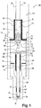
- a fuel injector 10 is an assembly of metal components comprising fixed components and moving components.
- the essential fixed components of an injector include in particular an injector body 12, a solenoid actuator 14 provided with a holding spring 16 of a control valve stem 18, a control valve body 20 comprising a seat of the stem of the control valve 22, a spacer 24 between the body of the control valve 20 and an injection nozzle 26, a control chamber 28 comprising a ceiling 30 and a wall 32, and a needle seat Injection valve 34.
- the mobile components of the injector include in particular the stem of the control valve 18, the armature 36 of the control valve secured to the stem of the control valve 18 and the injection needle 38.
- the moving components of the injector are controlled via the control wires 15 of the the solenoid actuator communicating outside the injector through a connector arranged on the injector 10.
- the fixed components obviously have surfaces in contact with each other, called contact surfaces S.
- the moving components also have surfaces in contact with fixed components of the injector, also called contact surfaces S.
- the moving components also have surfaces coming into intermittent contact with other surfaces of the injector 10, also called contact surfaces S.
- contact surfaces S between two fixed components such that the contact surfaces S between the body of the solenoid actuator 14 and the body of the control valve 20 and also for example the contact surfaces S between the body of the control valve 20 and the spacer 24, the spacer 24 having a surface in contact with the control chamber 28.
- the contact surfaces S between a mobile component and a fixed component such as that the contact surfaces S between the injection needle 38 and its seat 34, and also the contact surfaces S between the injection needle 38 and the ceiling of the control chamber 30.
- the contact between the needle injection 38 and its seat 34 is established during non-injection phases.
- the injection needle 38 is in the closed position.
- the contact between the injection needle 38 and the ceiling of the control chamber 30 is established when the injection needle 38 is in the high stop position, that is to say at the end of the upstroke during the fuel injection.
- the injection needle 38 is also in constant contact with the injection nozzle 26 in which it performs its movement back and forth.
- the stem of the control valve 18 also has a surface in intermittent contact with its seat 22. The contact between the stem of the control valve 18 and its seat 22 is established when the control valve is closed.
- the stem of the control valve 18 has a permanent contact with the holding spring 16 of the solenoid actuator.
- the armature 36 of the control valve, integral with the stem of the control valve 18, also has contact with the body of the solenoid actuator 14. contact between the armature 36 of the control valve and the body of the solenoid actuator 14 is established when the control valve is open and the armature 36 of the control valve is in high abutment.
- the set of contact surfaces S between the various metal components of the injector 10 has a virtually zero electrical resistivity.
- the invention consists in arranging resistive surface coatings 40 on a plurality of contact surfaces S of the injector 10 and to be associated with the overall electrical resistivity R7 of the injector 10 measured between the body of the solenoid actuator 14 and the injector body 12 at least 3 ohmic values of overall electrical resistivity, preferably distinct, R7A, R7B and R7C, varying according to the kinetics of the moving components such as for example the injection needle 38 or the rod of the control valve 18.
- resistive surface coatings 40 having technical characteristics such as, for example, electrical resistivity, makes it possible to model the injector 10 by at least one equivalent resistive electrical circuit ( Fig. 2 ).
- the resistivity of the permanent contacts and established contacts will be like the surface coating resistive 40 which covers them.
- the permanent contacts and the established contacts covered with resistive surface coatings can be likened to electrical resistances having values ranging from the order of the ohm up to the hundred kilo-ohms according to the embodiment of the invention.
- the resistive surface coatings 40 preferably have a thickness of a few ⁇ m, for example a thickness of between 1 ⁇ m and 5 ⁇ m.
- Their rigidity comparable to that of steel, or even higher, is of the order of Giga Pascal (GPa), preferably between 1 GPa and 35 GPa.
- GPa Giga Pascal
- the contact surfaces S may each be coated independently of each other of different types of surface coatings.
- the electrical resistivity between the body of the injector 12 and the body of the injection nozzle 36 is almost zero. This means that there is no resistive surface coating between these metal parts.
- a non-resistive surface coating or a very low resistance coating that is to say with a zero or very low resistance value, such as for example having a maximum resistivity of the order of one ohm, can be arranged between these two metal parts for reasons of protection against premature wear of metal parts.
- the electrical resistivity is also almost zero between the body of the solenoid actuator 14 and the body of the control valve 20, between the body of the control valve 20 and the spacer 24 and also between the 20 control valve body and the ceiling of the control chamber 30.
- a non-resistive surface coating or very low resistance that is to say, with zero or very low ohmic value, such as for example having a maximum resistivity of the order of one ohm, can be arranged between these parts metal for reasons of protection against premature wear of metal parts.
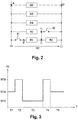
- the figure 2 represents a first example of the modeling of the equivalent overall electrical resistivity R7 of the fuel injector 10 according to the arrangement of the resistive surface coatings on the contact surfaces S presented according to the first embodiment illustrated by the figure 1 .
- the equivalent electrical circuit of the injector 10 comprises a first contact point A equivalent to the electrical potential of the body of the injection nozzle 26 and the body of the injector 12, a second contact point B equivalent to the electrical potential of the seat of the injection needle 34, a third point C of contact equivalent to the electric potential of the injection needle 38, a fourth contact point D equivalent to the electrical potential of the spacer 24, the body of the control valve 20, the body of the solenoid actuator 14, and the ceiling of the control chamber 30, a first switch S1 connected between the first contact point A and the second contact point B, a first connected resistor R1 between the second contact point B and the third contact point C, a second connected resistor R2 between the first contact point A and the third contact point C, a third resistor R3 connected between the third contact point C and
- the overall electrical resistivity R7 of the first topology illustrated by the figure 2 varies depending on the position of the injection needle 38.
- a first value R7A of the overall electrical resistivity R7 is measurable when the injection needle 38 is in contact with its seat 34.
- the injector 10 is said to closed position. This occurs during a first phase T1 at the beginning of the injection cycle and during a fifth phase T5 at the end of the injection cycle.
- the first switch S1 is closed since the injection needle 38 is in contact with its seat 34, while the second switch S2 is open since the injection needle 38 n It is not in contact with the ceiling of the control chamber 30.
- the injector 10 When the injection needle 38 makes its way towards the ceiling of the control chamber 30, a second value R7B of the overall electrical resistivity R7 is measurable.
- the injector 10 is then in a second phase T2 corresponding to the start of injection regime.
- the first switch S1 is open since the injection needle 38 is no longer in contact with its seat 34, and the second switch S2 is also open since the injection needle 38 is not not in contact with the ceiling of the control chamber 30.
- the injector 10 When the injection needle 38 has completed its travel in high abutment with the ceiling of the control chamber 30, the injector 10 is in a third phase T3 in steady state injection. During this third phase T3, a third R7C value of the overall electrical resistivity R7 is measurable. During this third phase T3, the first switch S1 is open since the injection needle 38 is no longer in contact with its seat 34, and the second switch S2 is closed since the injection needle 38 is in contact with the ceiling of the control chamber 30. When the injector 10 is in end of injection mode, the injection needle 38 travels from the ceiling of the control chamber 30 to its seat 34. The injector 10 is in a fourth phase T4.
- the value of the overall electrical resistivity R7 is equivalent to the second value R7B identified during the injection start phase since the first switch S1 and the second switch S2 are open, the injection needle 38 being neither in contact with its seat 34 nor in contact with the ceiling of the control chamber 30.
- a first solution may be to access the measurement of the overall electrical resistivity R7 between the electrical mass defined by the body of the injector 12 and a wire connected to the body of the solenoid actuator 14.
- This wire may advantageously join the part external of the injector 10 following a set of grooves in the metal parts leading to a connector accessible by a means for measuring the overall electrical resistivity R7.
- This wire accessible from the outside of the injector 10 is therefore the measuring wire of the overall electrical resistivity R7.
- the orders of magnitude of the resistors R1, R2 and R3 may be of the order of a few tens of ohms to tens of kilo-ohms with in particular preferably a value of R2 twice greater than the value of R3. This order of magnitude allows an optimal detection of the movement of the injection needle 38 and more particularly of being able to determine the travel time of the injection needle 38 between its closed position and its high abutment position and Conversely.
- the orders of magnitude of the resistors R4, R5 and R6 may be greater than one hundred kilo-ohms in order to limit the leakage currents to the body of the injector 12 during the measurement phases.
- a second solution may be to add an additional electrical resistance between the body of the solenoid actuator 14 and one of the control wires 15 of the solenoid actuator. In this way, the measurement of the overall electrical resistivity R7 is done directly between the control wire connected to this additional electrical resistance and the electrical mass defined by the body of the injector 12. In other words, the control wire connected to this additional electrical resistance is the measuring wire of the overall electrical resistivity R7 of the injector 10.
- the orders of magnitude of the resistors R1, R2 and R3 may be of the order of several tens of ohms with especially preferably a value of R2 twice as large as the value of R3. This order of magnitude allows an optimal detection of the movement of the injection needle 38 and more particularly to be able to determine the travel time of the injection needle 38 between its closed position and its high abutment position and vice versa.
- the orders of magnitude of the resistors R4, R5 and R6 may be greater than ten kilo-ohms in order to limit the leakage currents to the body of the injector 12 during the measurement phases.
- a third solution may be to add between the body of the solenoid actuator 14 and one of the control wires 15 of the solenoid actuator a parallel electronic structure comprising a first resistor in series with a first diode and a second resistor in series. with a second diode mounted in opposite direction to the first diode.
- the control wire connected to this electronic structure is the measuring wire of the overall electrical resistivity R7 of the injector 10.
- the electrical mass can be defined by the body of the injector 12. This topology advantageously makes it possible to keep constant the current flowing in the injector 10 during the opening and closing phases of the injection needle 38.
- this topology makes it possible to maintain a constant absolute value of the current of control of the solenoid actuator at control voltage differences supported by the solenoid of the actuator.
- the ratio between the values of the first resistance and the second resistance of this parallel structure is ten.
- the greatest resistance value is attributed to the first resistance which is traversed by the current flowing in the injector 10 when the injection needle38 is in the closed position.
- the polarization of the first diode allows the circulation of the body current of the solenoid actuator 14 to the seat of the injection needle 34 when the injection needle 38 is in the closed position, the current ending its travel through the electrical mass defined by the body of the injector 12.
- the orders of magnitude of the resistors R1, R2 and R3 may be of the order of a few tens of ohms with, in particular, preferably a value of R2 twice as large as the value of R3. This order of magnitude allows an optimal detection of the movement of the injection needle 38 and more particularly to be able to determine the travel time of the injection needle 38 between its closed position and its high abutment position and vice versa.
- the orders of magnitude of the resistors R4, R5 and R6 may be greater than ten kilo-ohms in order to limit the leakage currents to the body of the injector 12 during the measurement phases.
- the fuel injector 10 arranged with the resistive surface coatings 40 can be diagnosed. It is a question of proposing a first method of measuring the position and the speed of the injection needle 38 of the injector 10 and also of measuring the degree of wear of the resistive surface coatings 40.
- the value of overall resistivity R7 of the injector 10 measured at a given instant can be compared with the 3 ohmic values of global electrical resistivity R7A, R7B and R7C known. If the measured ohmic value is comparable to the first value R7A then the injection needle 38 is in its closed position, that is to say in the low abutment in its seat 34.
- the injection needle 38 in high abutment, that is to say in contact with the ceiling of the control chamber 30. If the measured ohmic value is comparable to the second value R7B then the needle Injection 38 is in its course.
- the direction of the race can be determined according to the previous value, different from R7B, measured. If the previous value of the measured global electrical resistivity R7 was the first value R7A, then the direction of travel of the injection needle 38 is said amount, that is to say the seat of the needle. injection 34 to the ceiling of the control chamber 30.
- the direction of travel of the injection needle is said to be descending, that is, that is, from the ceiling of the control chamber 30 towards the seat of the injection needle 34.
- an extremely fast sampling for example of the order of one tenth of the micro second, makes it possible to determine the temporal flow T between each change in the value of the overall electrical resistivity R7 measured.
- the identified absolute value of the smallest result resulting from the difference between the value of the measured overall electrical resistivity R7 with respectively the first value R7A, the second value R7B and the third value R7C at a given instant is proportional to the degree of wear of the resistive surface coatings 40.
- the wear of the resistive surface coatings 40 causes a drift of the overall electrical resistivity R7 of the injector. This drift can make it possible to activate an alert signal in the event of a value estimated to be a nuisance for the operation of the injector 10.
- a periodic self-calibration method can make it possible to regularly update the reference values of the overall electrical resistivity R7, that is to say an update of the 3 ohmic values of global electrical resistivity R7A, R7B and R7C, thus making it possible to overcome the drifts of the overall electrical resistivity R7 due for example to the temperature
- the electrical resistivity between the body of the injector 12 and the body of the injection nozzle 26 is almost zero. This means that there is no resistive surface coating between these metal parts.
- a non-resistive surface coating or a very low resistance coating that is to say with a zero or very low resistance value, such as for example having a maximum resistivity of the order of one ohm, can be arranged between these two metal parts for reasons of protection against premature wear of metal parts.
- the electrical resistivity between the body of the injector 12 and the body of the control valve 20 is almost zero. This means that there is no resistive surface coating between these metal parts.
- a non-resistive surface coating or a very low resistance coating that is to say with a zero or very low resistance value, such as for example having a maximum resistivity of the order of one ohm, can be arranged between these two metal parts for reasons of protection against premature wear of metal parts.
- the electrical resistivity between the injection needle 38 and the wall of the control chamber 32 is almost zero. This means that there is no resistive surface coating between these metal parts.
- a non-resistive surface coating or very low resistance that is to say Ohmic null or very low, such as having a maximum resistivity of the order of one ohm, can be arranged between these two metal parts for reasons of protection against premature wear of metal parts.
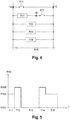
- the equivalent electric circuit of the injector 10 comprises a first contact point 1A equivalent to the electric potential of the injection needle 38, the spacer 24 and the wall of the control chamber 32, a second point 1B of contact equivalent to the electric potential of the seat 34 of the injection needle, a third contact point 1C equivalent to the electrical potential of the body of the injection nozzle 26 and the ceiling of the control chamber 30, a first switch S11 connected between the first contact point 1A and the third contact point 1C, a second switch S 12 connected between the second contact point 1B and the third contact point 1C, a first resistor R11 connected between the first contact point 1A and the contact point 1C.
- the overall electrical resistivity R15 of the injector is therefore measurable between the first contact point 1A and the third contact point 1C.
- the body of the injector 12 can act as an electrical mass.
- the overall electrical resistivity R15 of the topology illustrated through the figure 4 varies according to the position of the injection needle 38.
- a first value R15A of the overall electrical resistivity R15 is measurable when the injection needle 38 is in contact with its seat 34.
- the injector 10 is said in the closed position. This occurs during a first phase T11 at the beginning of the injection cycle and during a fifth phase T15 at the end of the injection cycle.
- the second switch S 12 is closed since the injection needle 38 is in contact with its seat 34, while the first switch S11 is open since the injection needle 38 does not contact the ceiling of the control chamber 30.
- a second R15B value of the overall electrical resistivity R15 is measurable.
- the injector 10 is then in a second phase T12 corresponding to the start of injection regime.
- the second switch S12 is open since the injection needle 38 is no longer in contact with its seat, and the first switch S11 is also open since the injection needle 38 is not in contact with the ceiling of the control chamber 30.
- the injector 10 is in a third phase T13 in steady state injection.
- a third value R15C of the overall electrical resistivity R15 is measurable.
- the second switch S12 is open since the injection needle 38 is no longer in contact with its seat 34, and the first switch S11 is closed since the injection needle 38 is in contact with the ceiling of the control chamber 30.
- This third R15C value of overall electrical resistivity R15 is then almost zero.
- the injector 10 is in end of injection mode, the injection needle 38 runs from the ceiling of the control chamber 30 to its seat.
- the injector is in a fourth phase T14.
- the value of the overall electrical resistivity R15 is equivalent to the second value R15B identified during the injection start phase since the first switch S11 and the second switch S12 are open, the injection needle 38 not in contact with its seat 34, or in contact with the ceiling of the control chamber 30.
- a first solution may be to access the measurement of the overall electrical resistivity R15 between the electrical mass defined by the body of the injector 12 and a wire connected to the wall of the control chamber 32.
- This wire may advantageously join the outer part the injector following a set of grooves in the metal parts leading to a connector accessible by a means of measuring the overall electrical resistivity R15.
- the use of the channels of the injector as passage of the wire or the micro drilling of the body of the injector 12 to the control chamber 28 allowing the passage of the wire may also be possible.
- This wire accessible from the outside of the injector is the measuring wire of the overall electrical resistivity R15.
- a second solution may be to add an additional electrical resistance between the wall of the control chamber 32 and one of the control wires 15 of the solenoid actuator.
- the measurement of the overall electrical resistivity R15 is accessible between the control wire of the solenoid actuator connected to this additional electrical resistance and the electrical mass defined by the body of the injector 12.
- the wire of control connected to this electrical resistance is the measuring wire of the overall electrical resistivity R15 of the injector 10.
- a third solution may be to add between the wall of the control chamber 32 and one of the control wires 15 of the solenoid actuator a parallel electronic structure comprising a first resistor in series with a first diode and a second resistor in series with a second diode mounted in the opposite direction to the first diode.
- the control wire connected to this electronic structure is the measuring wire of the overall electrical resistivity R15 of the injector.
- the electrical mass is defined by the body of the injector 12.
- this topology makes it possible to maintain a constant absolute value of the control current of the solenoid actuator at control voltage differences supported by the solenoid of the actuator.
- the ratio between the values of the first resistance and the second resistance of this parallel structure is ten.
- the greatest resistance value is attributed to the first resistance which is traversed by the current flowing in the injector 10 when the injection needle 38 is in the closed position.
- the polarization of the first diode allows the circulation of the body current of the solenoid actuator 14 to the seat of the injection needle 34 when the injection needle 38 is in the closed position, the current ending its travel through the electrical mass defined by the body of the injector 12.
- the measurement of the overall electrical resistivity R15 is accessible between the control wire of the solenoid actuator and the electrical mass defined by the body of the injector 12.
Landscapes
- Engineering & Computer Science (AREA)
- Chemical & Material Sciences (AREA)
- Combustion & Propulsion (AREA)
- Mechanical Engineering (AREA)
- General Engineering & Computer Science (AREA)
- Physics & Mathematics (AREA)
- General Physics & Mathematics (AREA)
- Analytical Chemistry (AREA)
- Electromagnetism (AREA)
- Fuel-Injection Apparatus (AREA)
- Fuel Cell (AREA)
Claims (5)
- Kraftstoffeinspritzventil (10), enthaltend:- feststehende Metallteile, insbesondre einen Ventilkörper (12), ein Solenoidstellglied (14), das mit einer Haltefeder (16) zum Halten eines Steuerventilschaft (18) versehen ist, einen Steuerventilkörper (20) mit einem Steuerventilschaftsitz (22), eine Verstrebung (24) zwischen dem Steuerventilkörper (20) und einer Einspritzdüse (26), einen Steuerraum (28) und einen Einspritznadelsitz (34),- bewegliche Metallteile, insbesondere den Steuerventilschaft (18) und dessen Anker (36) und die Einspritznadel (38),wobei das Solenoidstellglied (14) auch Steuerleitungen (15) aufweist, die mit dem Außenraum des Einspritzventils (10) kommunizieren,
wobei die in Kontakt miteinander stehenden Oberflächen der Metallteile Kontaktflächen (S) sind,
wobei
resistive Oberflächenbeschichtungen (40) an mehreren Kontaktflächen (S) angeordnet sind, und
der spezifische elektrische Gesamtwiderstand (R7) des Einspritzventils (10) zwischen dem Körper des Solenoidstellglieds (14) und dem Körper des Einspritzventils (12) je nach Kinetik der Einspritznadel (38) des Einspritzventils (10) um drei verschiedene Widerstandswerte (R7A, R7B, R7C) intermittierend variiert,
dadurch gekennzeichnet, dass
die resistiven Oberflächenbeschichtungen (40) angeordnet sind auf:zumindest einer Kontaktfläche (S) zwischen dem Sitz (34) der Einspritznadel (38) und der Einspritznadel (38),zumindest einer Kontaktfläche (S) zwischen dem Körper der Einspritzdüse (26) und der Einspritznadel (38),zumindest einer Kontaktfläche (S) zwischen der Einspritznadel (38) und der Verstrebung (24),zumindest einer Kontaktfläche (S) zwischen dem Körper der Einspritzdüse (26) und der Verstrebung (24),zumindest einer Kontaktfläche (S) zwischen dem Körper des Einspritzventils (12) und dem Körper des Steuerventils (20),zumindest einer Kontaktfläche (S) zwischen dem Körper des Einspritzventils (12) und dem Körper des Solenoidstellglieds (14). - Kraftstoffeinspritzventil (10) nach dem vorangehenden Anspruch, enthaltend einen zusätzlichen elektrischen Widerstand, der zwischen dem Körper des Solenoidstellglieds (14) und einer seiner Steuerleitungen (15) angeschlossen ist, wobei die Steuerleitung die Messleitung zum Messen des spezifischen elektrischen Gesamtwiderstands (R7) ist.
- Kraftstoffeinspritzventil (10) nach Anspruch 1, enthaltend einen Stromkreis mit paralleler Topologie, der zwischen dem Körper des Solenoidstellglieds (14) und einer der Steuerleitungen (15) des Stellglieds angeschlossen ist, wobei die Steuerleitung die Messleitung zum Messen des spezifischen elektrischen Gesamtwiderstands (R7) ist, wobei der parallele Stromkreis einen ersten elektrischen Widerstand in Reihe mit einer ersten Diode und einen zweiten elektrischen Widerstand in Reihe mit einer zweiten Diode aufweist, die in Gegenrichtung zur ersten Diode geschaltet ist.
- Kraftstoffeinspritzventil (10) nach Anspruch 1, enthaltend eine Leitung, die mit dem Körper des Solenoidstellglieds (14) verbunden ist, wobei die mit dem Außenteil des Einspritzventils (10) verbundene Leitung die Messleitung zum Messen des spezifischen elektrischen Gesamtwiderstands (R7) ist.
- Kraftstoffeinspritzventil (10) nach einem der vorangehenden Ansprüche, wobei jede der resistiven Oberflächenbeschichtungen (40), die an den Kontaktflächen (S) angeordnet sind, aus der Familie der amorphen Kohlenstoffe (a-C) oder vom keramischen Typ ist.
Applications Claiming Priority (2)
| Application Number | Priority Date | Filing Date | Title |
|---|---|---|---|
| FR1361006A FR3013080A1 (fr) | 2013-11-12 | 2013-11-12 | Injecteur de carburant |
| PCT/EP2014/073662 WO2015071132A1 (fr) | 2013-11-12 | 2014-11-04 | Injecteur de carburant |
Publications (2)
| Publication Number | Publication Date |
|---|---|
| EP3069005A1 EP3069005A1 (de) | 2016-09-21 |
| EP3069005B1 true EP3069005B1 (de) | 2018-02-28 |
Family
ID=50069133
Family Applications (1)
| Application Number | Title | Priority Date | Filing Date |
|---|---|---|---|
| EP14802330.2A Active EP3069005B1 (de) | 2013-11-12 | 2014-11-04 | Kraftstoffeinspritzer |
Country Status (7)
| Country | Link |
|---|---|
| US (1) | US9726126B2 (de) |
| EP (1) | EP3069005B1 (de) |
| JP (1) | JP6441923B2 (de) |
| KR (1) | KR102185717B1 (de) |
| CN (1) | CN105705769B (de) |
| FR (1) | FR3013080A1 (de) |
| WO (1) | WO2015071132A1 (de) |
Families Citing this family (14)
| Publication number | Priority date | Publication date | Assignee | Title |
|---|---|---|---|---|
| GB201511007D0 (en) | 2015-06-23 | 2015-08-05 | Delphi Int Operations Lux Srl | Nozzle assembly with adaptive closed signal |
| FR3043144B1 (fr) | 2015-10-29 | 2019-08-02 | Delphi Technologies Ip Limited | Injecteur de carburant |
| DE102015225733A1 (de) * | 2015-12-17 | 2017-06-22 | Robert Bosch Gmbh | Kraftstoffeinspritzdüse |
| DE102016203822B4 (de) * | 2016-03-09 | 2017-12-07 | Robert Bosch Gmbh | Kraftstoffeinspritzventil |
| FR3049657B1 (fr) * | 2016-04-01 | 2018-05-11 | Delphi Technologies Ip Limited | Injecteur de carburant |
| US20190120188A1 (en) * | 2016-04-01 | 2019-04-25 | Delphi Technologies Ip Limited | Fuel injector |
| GB2549095A (en) * | 2016-04-04 | 2017-10-11 | Delphi Int Operations Luxembourg Sarl | Fuel injector |
| FR3050771B1 (fr) | 2016-04-29 | 2018-06-01 | Delphi Technologies Ip Limited | Injecteur de carburant |
| DE102016220461A1 (de) * | 2016-10-19 | 2018-04-19 | Robert Bosch Gmbh | Verfahren zur Ermittlung des Drucks in einem Brennraum einer Brennkraftmaschine, Kraftstoffinjektor |
| DE102017116379A1 (de) * | 2017-07-20 | 2019-01-24 | Liebherr-Components Deggendorf Gmbh | Vorrichtung zur Zustandserfassung eines Injektors |
| GB2565316A (en) * | 2017-08-10 | 2019-02-13 | Delphi Int Operations Luxembourg Sarl | Circuit arrangement for fuel injector switch |
| GB2570663A (en) * | 2018-01-31 | 2019-08-07 | Delphi Automotive Systems Lux | Fuel Injector For An Internal Combustion Engine |
| US11067028B2 (en) * | 2019-01-16 | 2021-07-20 | Caterpillar Inc. | Fuel injector |
| GB2580624B (en) * | 2019-01-17 | 2021-09-15 | Delphi Tech Ip Ltd | Fuel injector |
Family Cites Families (12)
| Publication number | Priority date | Publication date | Assignee | Title |
|---|---|---|---|---|
| JPS6045872U (ja) * | 1983-09-07 | 1985-03-30 | 株式会社ボッシュオートモーティブ システム | 燃料噴射弁 |
| JPS6085248A (ja) * | 1983-10-18 | 1985-05-14 | Diesel Kiki Co Ltd | 燃料噴射弁 |
| JPH06501080A (ja) * | 1990-09-18 | 1994-01-27 | ルーカス・インダストリーズ・パブリック・リミテッド・カンパニー | 燃料噴射ノズル |
| JP3042120B2 (ja) * | 1991-12-10 | 2000-05-15 | 株式会社デンソー | 噴射時期検出用燃料噴射ノズル |
| GB9225005D0 (en) * | 1992-11-30 | 1993-01-20 | Perkins Ltd | Improvements in or relating to fluid-flow control valves |
| JP4587156B2 (ja) * | 2000-08-21 | 2010-11-24 | ボルボ ラストバグナー アーベー | ニードル位置検出装置 |
| DE10313623A1 (de) * | 2003-03-26 | 2004-10-21 | Siemens Ag | Kontaktiervorrichtung für einen Injektor eines Einspritzsystems für die Kraftstoffeinspritzung sowie Injektor mit einer Kontaktiervorrichtung |
| DE10319329A1 (de) * | 2003-04-29 | 2004-11-25 | Siemens Ag | Einspritzventil mit Sitzkontaktschalter |
| DE10338489B3 (de) * | 2003-08-21 | 2004-12-16 | Siemens Ag | Einspritzventil mit kapazitivem Ventilhubsensor |
| DE102005060667A1 (de) * | 2005-12-19 | 2007-06-28 | Robert Bosch Gmbh | Hochdruckverbindung und Verfahren zum Herstellen einer Hochdruckverbindung |
| DE102007056913A1 (de) * | 2007-11-26 | 2009-05-28 | Robert Bosch Gmbh | Einspritzdüse für Kraftstoff mit Kugelventil |
| DE102011016168B4 (de) * | 2011-04-05 | 2015-02-12 | L'orange Gmbh | Kraftstoffinjektor für eine Brennkraftmaschine |
-
2013
- 2013-11-12 FR FR1361006A patent/FR3013080A1/fr active Pending
-
2014
- 2014-11-04 US US15/036,350 patent/US9726126B2/en active Active
- 2014-11-04 KR KR1020167012397A patent/KR102185717B1/ko active Active
- 2014-11-04 CN CN201480062043.0A patent/CN105705769B/zh active Active
- 2014-11-04 JP JP2016529881A patent/JP6441923B2/ja not_active Expired - Fee Related
- 2014-11-04 EP EP14802330.2A patent/EP3069005B1/de active Active
- 2014-11-04 WO PCT/EP2014/073662 patent/WO2015071132A1/fr not_active Ceased
Also Published As
| Publication number | Publication date |
|---|---|
| JP6441923B2 (ja) | 2018-12-19 |
| JP2017501326A (ja) | 2017-01-12 |
| KR20160083875A (ko) | 2016-07-12 |
| EP3069005A1 (de) | 2016-09-21 |
| KR102185717B1 (ko) | 2020-12-03 |
| US20160281665A1 (en) | 2016-09-29 |
| CN105705769A (zh) | 2016-06-22 |
| WO2015071132A1 (fr) | 2015-05-21 |
| US9726126B2 (en) | 2017-08-08 |
| CN105705769B (zh) | 2018-09-07 |
| FR3013080A1 (fr) | 2015-05-15 |
Similar Documents
| Publication | Publication Date | Title |
|---|---|---|
| EP3069005B1 (de) | Kraftstoffeinspritzer | |
| EP3169890B1 (de) | Kraftstoffinjektor | |
| WO2016203128A1 (fr) | Système électrique comportant un circuit de détection d'un défaut d'isolement électrique | |
| EP2087574A2 (de) | Verfahren zur verwaltung des aufladens einer wiederaufladbaren batterie | |
| EP2850445B1 (de) | System und entsprechendes verfahren zur bestimmung des ladezustandes einer batterie | |
| FR2929409A1 (fr) | Procede d'estimation de la charge d'une batterie d'un vehicule automobile | |
| FR3041426A1 (fr) | Procede de calibration automatique d'un capteur d'arbre a cames pour moteur de vehicule automobile | |
| FR3056299A1 (fr) | Procede de determination de la consommation en courant d'une charge active, par exemple une unite de traitement, et circuit electronique associe | |
| EP4134695A1 (de) | Überprüfung der messgenauigkeit eines stromzählers | |
| FR2964210A1 (fr) | Systeme de traitement de signaux redondants, procede associe, et aeronef comprenant un tel systeme | |
| WO2021170345A1 (fr) | Procédé d'estimation de l'état de santé énergétique d'une batterie | |
| FR2813444A1 (fr) | Procede de charge d'une batterie | |
| EP2619426A1 (de) | Vefahren zur adaptiven beurteilung der momentanen russlast eines partikelfiltes | |
| CA2786543C (fr) | Circuit de detection des positions de contacteurs dans une turbomachine | |
| FR3047573A1 (fr) | Procede de commande en tension d'un equipement monte dans un vehicule automobile | |
| FR3036480A1 (fr) | Capteur de proximite capacitif pour vehicule automobile | |
| FR2989777A1 (fr) | Correction d'une mesure de temperature d'une sonde de temperature de type a resistance thermometrique | |
| EP3264431B1 (de) | Bistabiler linearer elektromagnet | |
| EP2553694B1 (de) | Elektromagnetischer betätiger mit positionssteuerung und verfahren zur verwendung eines derartigen betätigers | |
| FR3049657A1 (fr) | Injecteur de carburant | |
| WO2004079176A1 (fr) | Procede de determination du gain d’un injecteur de carburant | |
| EP2889595B1 (de) | Verfahren zur Steuerung der Strom- oder Spannungsversorgung eines resistiven Temperatursensors, der in einem Tieftemperaturgehäuse eingebaut ist | |
| FR3045218A1 (fr) | Determination de parametres d'un modele dynamique pour une cellule electrochimique de batterie | |
| FR3050536A1 (fr) | Procede de determination de la vitesse de rotation d’une cage de retention d’un palier a roulement | |
| FR3003036A1 (fr) | Procede de mesure d’un courant circulant dans une branche d’un systeme comportant plusieurs branches |
Legal Events
| Date | Code | Title | Description |
|---|---|---|---|
| PUAI | Public reference made under article 153(3) epc to a published international application that has entered the european phase |
Free format text: ORIGINAL CODE: 0009012 |
|
| 17P | Request for examination filed |
Effective date: 20160613 |
|
| AK | Designated contracting states |
Kind code of ref document: A1 Designated state(s): AL AT BE BG CH CY CZ DE DK EE ES FI FR GB GR HR HU IE IS IT LI LT LU LV MC MK MT NL NO PL PT RO RS SE SI SK SM TR |
|
| AX | Request for extension of the european patent |
Extension state: BA ME |
|
| DAX | Request for extension of the european patent (deleted) | ||
| GRAP | Despatch of communication of intention to grant a patent |
Free format text: ORIGINAL CODE: EPIDOSNIGR1 |
|
| INTG | Intention to grant announced |
Effective date: 20170919 |
|
| GRAS | Grant fee paid |
Free format text: ORIGINAL CODE: EPIDOSNIGR3 |
|
| GRAA | (expected) grant |
Free format text: ORIGINAL CODE: 0009210 |
|
| AK | Designated contracting states |
Kind code of ref document: B1 Designated state(s): AL AT BE BG CH CY CZ DE DK EE ES FI FR GB GR HR HU IE IS IT LI LT LU LV MC MK MT NL NO PL PT RO RS SE SI SK SM TR |
|
| REG | Reference to a national code |
Ref country code: GB Ref legal event code: FG4D Free format text: NOT ENGLISH Ref country code: CH Ref legal event code: EP |
|
| REG | Reference to a national code |
Ref country code: AT Ref legal event code: REF Ref document number: 974434 Country of ref document: AT Kind code of ref document: T Effective date: 20180315 |
|
| REG | Reference to a national code |
Ref country code: IE Ref legal event code: FG4D Free format text: LANGUAGE OF EP DOCUMENT: FRENCH |
|
| REG | Reference to a national code |
Ref country code: DE Ref legal event code: R096 Ref document number: 602014021730 Country of ref document: DE |
|
| REG | Reference to a national code |
Ref country code: NL Ref legal event code: MP Effective date: 20180228 |
|
| REG | Reference to a national code |
Ref country code: LT Ref legal event code: MG4D |
|
| REG | Reference to a national code |
Ref country code: AT Ref legal event code: MK05 Ref document number: 974434 Country of ref document: AT Kind code of ref document: T Effective date: 20180228 |
|
| PG25 | Lapsed in a contracting state [announced via postgrant information from national office to epo] |
Ref country code: ES Free format text: LAPSE BECAUSE OF FAILURE TO SUBMIT A TRANSLATION OF THE DESCRIPTION OR TO PAY THE FEE WITHIN THE PRESCRIBED TIME-LIMIT Effective date: 20180228 Ref country code: FI Free format text: LAPSE BECAUSE OF FAILURE TO SUBMIT A TRANSLATION OF THE DESCRIPTION OR TO PAY THE FEE WITHIN THE PRESCRIBED TIME-LIMIT Effective date: 20180228 Ref country code: NO Free format text: LAPSE BECAUSE OF FAILURE TO SUBMIT A TRANSLATION OF THE DESCRIPTION OR TO PAY THE FEE WITHIN THE PRESCRIBED TIME-LIMIT Effective date: 20180528 Ref country code: CY Free format text: LAPSE BECAUSE OF FAILURE TO SUBMIT A TRANSLATION OF THE DESCRIPTION OR TO PAY THE FEE WITHIN THE PRESCRIBED TIME-LIMIT Effective date: 20180228 Ref country code: HR Free format text: LAPSE BECAUSE OF FAILURE TO SUBMIT A TRANSLATION OF THE DESCRIPTION OR TO PAY THE FEE WITHIN THE PRESCRIBED TIME-LIMIT Effective date: 20180228 Ref country code: NL Free format text: LAPSE BECAUSE OF FAILURE TO SUBMIT A TRANSLATION OF THE DESCRIPTION OR TO PAY THE FEE WITHIN THE PRESCRIBED TIME-LIMIT Effective date: 20180228 Ref country code: LT Free format text: LAPSE BECAUSE OF FAILURE TO SUBMIT A TRANSLATION OF THE DESCRIPTION OR TO PAY THE FEE WITHIN THE PRESCRIBED TIME-LIMIT Effective date: 20180228 |
|
| PG25 | Lapsed in a contracting state [announced via postgrant information from national office to epo] |
Ref country code: LV Free format text: LAPSE BECAUSE OF FAILURE TO SUBMIT A TRANSLATION OF THE DESCRIPTION OR TO PAY THE FEE WITHIN THE PRESCRIBED TIME-LIMIT Effective date: 20180228 Ref country code: BG Free format text: LAPSE BECAUSE OF FAILURE TO SUBMIT A TRANSLATION OF THE DESCRIPTION OR TO PAY THE FEE WITHIN THE PRESCRIBED TIME-LIMIT Effective date: 20180528 Ref country code: SE Free format text: LAPSE BECAUSE OF FAILURE TO SUBMIT A TRANSLATION OF THE DESCRIPTION OR TO PAY THE FEE WITHIN THE PRESCRIBED TIME-LIMIT Effective date: 20180228 Ref country code: RS Free format text: LAPSE BECAUSE OF FAILURE TO SUBMIT A TRANSLATION OF THE DESCRIPTION OR TO PAY THE FEE WITHIN THE PRESCRIBED TIME-LIMIT Effective date: 20180228 Ref country code: AT Free format text: LAPSE BECAUSE OF FAILURE TO SUBMIT A TRANSLATION OF THE DESCRIPTION OR TO PAY THE FEE WITHIN THE PRESCRIBED TIME-LIMIT Effective date: 20180228 Ref country code: GR Free format text: LAPSE BECAUSE OF FAILURE TO SUBMIT A TRANSLATION OF THE DESCRIPTION OR TO PAY THE FEE WITHIN THE PRESCRIBED TIME-LIMIT Effective date: 20180529 |
|
| PG25 | Lapsed in a contracting state [announced via postgrant information from national office to epo] |
Ref country code: MT Free format text: LAPSE BECAUSE OF FAILURE TO SUBMIT A TRANSLATION OF THE DESCRIPTION OR TO PAY THE FEE WITHIN THE PRESCRIBED TIME-LIMIT Effective date: 20180228 |
|
| PG25 | Lapsed in a contracting state [announced via postgrant information from national office to epo] |
Ref country code: IT Free format text: LAPSE BECAUSE OF FAILURE TO SUBMIT A TRANSLATION OF THE DESCRIPTION OR TO PAY THE FEE WITHIN THE PRESCRIBED TIME-LIMIT Effective date: 20180228 Ref country code: RO Free format text: LAPSE BECAUSE OF FAILURE TO SUBMIT A TRANSLATION OF THE DESCRIPTION OR TO PAY THE FEE WITHIN THE PRESCRIBED TIME-LIMIT Effective date: 20180228 Ref country code: EE Free format text: LAPSE BECAUSE OF FAILURE TO SUBMIT A TRANSLATION OF THE DESCRIPTION OR TO PAY THE FEE WITHIN THE PRESCRIBED TIME-LIMIT Effective date: 20180228 Ref country code: AL Free format text: LAPSE BECAUSE OF FAILURE TO SUBMIT A TRANSLATION OF THE DESCRIPTION OR TO PAY THE FEE WITHIN THE PRESCRIBED TIME-LIMIT Effective date: 20180228 Ref country code: PL Free format text: LAPSE BECAUSE OF FAILURE TO SUBMIT A TRANSLATION OF THE DESCRIPTION OR TO PAY THE FEE WITHIN THE PRESCRIBED TIME-LIMIT Effective date: 20180228 |
|
| REG | Reference to a national code |
Ref country code: DE Ref legal event code: R097 Ref document number: 602014021730 Country of ref document: DE |
|
| PG25 | Lapsed in a contracting state [announced via postgrant information from national office to epo] |
Ref country code: DK Free format text: LAPSE BECAUSE OF FAILURE TO SUBMIT A TRANSLATION OF THE DESCRIPTION OR TO PAY THE FEE WITHIN THE PRESCRIBED TIME-LIMIT Effective date: 20180228 Ref country code: SK Free format text: LAPSE BECAUSE OF FAILURE TO SUBMIT A TRANSLATION OF THE DESCRIPTION OR TO PAY THE FEE WITHIN THE PRESCRIBED TIME-LIMIT Effective date: 20180228 Ref country code: CZ Free format text: LAPSE BECAUSE OF FAILURE TO SUBMIT A TRANSLATION OF THE DESCRIPTION OR TO PAY THE FEE WITHIN THE PRESCRIBED TIME-LIMIT Effective date: 20180228 Ref country code: SM Free format text: LAPSE BECAUSE OF FAILURE TO SUBMIT A TRANSLATION OF THE DESCRIPTION OR TO PAY THE FEE WITHIN THE PRESCRIBED TIME-LIMIT Effective date: 20180228 |
|
| PLBE | No opposition filed within time limit |
Free format text: ORIGINAL CODE: 0009261 |
|
| STAA | Information on the status of an ep patent application or granted ep patent |
Free format text: STATUS: NO OPPOSITION FILED WITHIN TIME LIMIT |
|
| 26N | No opposition filed |
Effective date: 20181129 |
|
| REG | Reference to a national code |
Ref country code: DE Ref legal event code: R081 Ref document number: 602014021730 Country of ref document: DE Owner name: DELPHI TECHNOLOGIES IP LIMITED, BB Free format text: FORMER OWNER: DELPHI INTERNATIONAL OPERATIONS LUXEMBOURG S.A.R.L., BASCHARAGE, LU |
|
| PG25 | Lapsed in a contracting state [announced via postgrant information from national office to epo] |
Ref country code: SI Free format text: LAPSE BECAUSE OF FAILURE TO SUBMIT A TRANSLATION OF THE DESCRIPTION OR TO PAY THE FEE WITHIN THE PRESCRIBED TIME-LIMIT Effective date: 20180228 |
|
| REG | Reference to a national code |
Ref country code: GB Ref legal event code: 732E Free format text: REGISTERED BETWEEN 20190222 AND 20190227 |
|
| REG | Reference to a national code |
Ref country code: CH Ref legal event code: PL |
|
| PG25 | Lapsed in a contracting state [announced via postgrant information from national office to epo] |
Ref country code: MC Free format text: LAPSE BECAUSE OF FAILURE TO SUBMIT A TRANSLATION OF THE DESCRIPTION OR TO PAY THE FEE WITHIN THE PRESCRIBED TIME-LIMIT Effective date: 20180228 Ref country code: LU Free format text: LAPSE BECAUSE OF NON-PAYMENT OF DUE FEES Effective date: 20181104 |
|
| REG | Reference to a national code |
Ref country code: BE Ref legal event code: MM Effective date: 20181130 |
|
| REG | Reference to a national code |
Ref country code: IE Ref legal event code: MM4A |
|
| PG25 | Lapsed in a contracting state [announced via postgrant information from national office to epo] |
Ref country code: CH Free format text: LAPSE BECAUSE OF NON-PAYMENT OF DUE FEES Effective date: 20181130 Ref country code: LI Free format text: LAPSE BECAUSE OF NON-PAYMENT OF DUE FEES Effective date: 20181130 |
|
| PG25 | Lapsed in a contracting state [announced via postgrant information from national office to epo] |
Ref country code: IE Free format text: LAPSE BECAUSE OF NON-PAYMENT OF DUE FEES Effective date: 20181104 |
|
| PG25 | Lapsed in a contracting state [announced via postgrant information from national office to epo] |
Ref country code: BE Free format text: LAPSE BECAUSE OF NON-PAYMENT OF DUE FEES Effective date: 20181130 |
|
| PG25 | Lapsed in a contracting state [announced via postgrant information from national office to epo] |
Ref country code: TR Free format text: LAPSE BECAUSE OF FAILURE TO SUBMIT A TRANSLATION OF THE DESCRIPTION OR TO PAY THE FEE WITHIN THE PRESCRIBED TIME-LIMIT Effective date: 20180228 |
|
| PG25 | Lapsed in a contracting state [announced via postgrant information from national office to epo] |
Ref country code: PT Free format text: LAPSE BECAUSE OF FAILURE TO SUBMIT A TRANSLATION OF THE DESCRIPTION OR TO PAY THE FEE WITHIN THE PRESCRIBED TIME-LIMIT Effective date: 20180228 |
|
| PG25 | Lapsed in a contracting state [announced via postgrant information from national office to epo] |
Ref country code: HU Free format text: LAPSE BECAUSE OF FAILURE TO SUBMIT A TRANSLATION OF THE DESCRIPTION OR TO PAY THE FEE WITHIN THE PRESCRIBED TIME-LIMIT; INVALID AB INITIO Effective date: 20141104 Ref country code: MK Free format text: LAPSE BECAUSE OF NON-PAYMENT OF DUE FEES Effective date: 20180228 |
|
| PG25 | Lapsed in a contracting state [announced via postgrant information from national office to epo] |
Ref country code: IS Free format text: LAPSE BECAUSE OF FAILURE TO SUBMIT A TRANSLATION OF THE DESCRIPTION OR TO PAY THE FEE WITHIN THE PRESCRIBED TIME-LIMIT Effective date: 20180628 |
|
| PGFP | Annual fee paid to national office [announced via postgrant information from national office to epo] |
Ref country code: DE Payment date: 20201127 Year of fee payment: 7 Ref country code: GB Payment date: 20201127 Year of fee payment: 7 |
|
| REG | Reference to a national code |
Ref country code: DE Ref legal event code: R119 Ref document number: 602014021730 Country of ref document: DE |
|
| GBPC | Gb: european patent ceased through non-payment of renewal fee |
Effective date: 20211104 |
|
| PG25 | Lapsed in a contracting state [announced via postgrant information from national office to epo] |
Ref country code: GB Free format text: LAPSE BECAUSE OF NON-PAYMENT OF DUE FEES Effective date: 20211104 Ref country code: DE Free format text: LAPSE BECAUSE OF NON-PAYMENT OF DUE FEES Effective date: 20220601 |
|
| P01 | Opt-out of the competence of the unified patent court (upc) registered |
Effective date: 20230327 |
|
| PGFP | Annual fee paid to national office [announced via postgrant information from national office to epo] |
Ref country code: FR Payment date: 20251013 Year of fee payment: 12 |