EP3067237B1 - Dispositif d'affichage pour véhicule, notamment véhicule utilitaire - Google Patents
Dispositif d'affichage pour véhicule, notamment véhicule utilitaire Download PDFInfo
- Publication number
- EP3067237B1 EP3067237B1 EP16155508.1A EP16155508A EP3067237B1 EP 3067237 B1 EP3067237 B1 EP 3067237B1 EP 16155508 A EP16155508 A EP 16155508A EP 3067237 B1 EP3067237 B1 EP 3067237B1
- Authority
- EP
- European Patent Office
- Prior art keywords
- image
- area
- characteristic
- fade
- display system
- Prior art date
- Legal status (The legal status is an assumption and is not a legal conclusion. Google has not performed a legal analysis and makes no representation as to the accuracy of the status listed.)
- Active
Links
- 238000004364 calculation method Methods 0.000 claims description 23
- 238000012545 processing Methods 0.000 claims description 6
- 238000007620 mathematical function Methods 0.000 claims description 5
- 230000001419 dependent effect Effects 0.000 claims description 4
- 238000010191 image analysis Methods 0.000 claims description 3
- 238000012986 modification Methods 0.000 claims description 3
- 230000004048 modification Effects 0.000 claims description 3
- 238000005259 measurement Methods 0.000 description 22
- 230000008859 change Effects 0.000 description 9
- 238000001454 recorded image Methods 0.000 description 5
- 230000000875 corresponding effect Effects 0.000 description 4
- 238000012935 Averaging Methods 0.000 description 3
- 230000002950 deficient Effects 0.000 description 2
- 238000013461 design Methods 0.000 description 2
- 238000001514 detection method Methods 0.000 description 2
- 238000011156 evaluation Methods 0.000 description 2
- 238000012886 linear function Methods 0.000 description 2
- 238000000034 method Methods 0.000 description 2
- 230000008569 process Effects 0.000 description 2
- 230000006978 adaptation Effects 0.000 description 1
- 239000003086 colorant Substances 0.000 description 1
- 230000003111 delayed effect Effects 0.000 description 1
- 230000004069 differentiation Effects 0.000 description 1
- 238000005457 optimization Methods 0.000 description 1
- 238000000926 separation method Methods 0.000 description 1
- 239000013589 supplement Substances 0.000 description 1
- 230000007704 transition Effects 0.000 description 1
Images


Classifications
-
- G—PHYSICS
- G06—COMPUTING; CALCULATING OR COUNTING
- G06T—IMAGE DATA PROCESSING OR GENERATION, IN GENERAL
- G06T11/00—2D [Two Dimensional] image generation
- G06T11/60—Editing figures and text; Combining figures or text
-
- G—PHYSICS
- G09—EDUCATION; CRYPTOGRAPHY; DISPLAY; ADVERTISING; SEALS
- G09G—ARRANGEMENTS OR CIRCUITS FOR CONTROL OF INDICATING DEVICES USING STATIC MEANS TO PRESENT VARIABLE INFORMATION
- G09G3/00—Control arrangements or circuits, of interest only in connection with visual indicators other than cathode-ray tubes
- G09G3/20—Control arrangements or circuits, of interest only in connection with visual indicators other than cathode-ray tubes for presentation of an assembly of a number of characters, e.g. a page, by composing the assembly by combination of individual elements arranged in a matrix no fixed position being assigned to or needed to be assigned to the individual characters or partial characters
-
- B—PERFORMING OPERATIONS; TRANSPORTING
- B60—VEHICLES IN GENERAL
- B60R—VEHICLES, VEHICLE FITTINGS, OR VEHICLE PARTS, NOT OTHERWISE PROVIDED FOR
- B60R1/00—Optical viewing arrangements; Real-time viewing arrangements for drivers or passengers using optical image capturing systems, e.g. cameras or video systems specially adapted for use in or on vehicles
- B60R1/20—Real-time viewing arrangements for drivers or passengers using optical image capturing systems, e.g. cameras or video systems specially adapted for use in or on vehicles
- B60R1/22—Real-time viewing arrangements for drivers or passengers using optical image capturing systems, e.g. cameras or video systems specially adapted for use in or on vehicles for viewing an area outside the vehicle, e.g. the exterior of the vehicle
- B60R1/23—Real-time viewing arrangements for drivers or passengers using optical image capturing systems, e.g. cameras or video systems specially adapted for use in or on vehicles for viewing an area outside the vehicle, e.g. the exterior of the vehicle with a predetermined field of view
- B60R1/26—Real-time viewing arrangements for drivers or passengers using optical image capturing systems, e.g. cameras or video systems specially adapted for use in or on vehicles for viewing an area outside the vehicle, e.g. the exterior of the vehicle with a predetermined field of view to the rear of the vehicle
-
- H—ELECTRICITY
- H04—ELECTRIC COMMUNICATION TECHNIQUE
- H04N—PICTORIAL COMMUNICATION, e.g. TELEVISION
- H04N7/00—Television systems
- H04N7/18—Closed-circuit television [CCTV] systems, i.e. systems in which the video signal is not broadcast
- H04N7/183—Closed-circuit television [CCTV] systems, i.e. systems in which the video signal is not broadcast for receiving images from a single remote source
-
- B—PERFORMING OPERATIONS; TRANSPORTING
- B60—VEHICLES IN GENERAL
- B60R—VEHICLES, VEHICLE FITTINGS, OR VEHICLE PARTS, NOT OTHERWISE PROVIDED FOR
- B60R2300/00—Details of viewing arrangements using cameras and displays, specially adapted for use in a vehicle
- B60R2300/30—Details of viewing arrangements using cameras and displays, specially adapted for use in a vehicle characterised by the type of image processing
- B60R2300/304—Details of viewing arrangements using cameras and displays, specially adapted for use in a vehicle characterised by the type of image processing using merged images, e.g. merging camera image with stored images
- B60R2300/305—Details of viewing arrangements using cameras and displays, specially adapted for use in a vehicle characterised by the type of image processing using merged images, e.g. merging camera image with stored images merging camera image with lines or icons
-
- G—PHYSICS
- G09—EDUCATION; CRYPTOGRAPHY; DISPLAY; ADVERTISING; SEALS
- G09G—ARRANGEMENTS OR CIRCUITS FOR CONTROL OF INDICATING DEVICES USING STATIC MEANS TO PRESENT VARIABLE INFORMATION
- G09G2320/00—Control of display operating conditions
- G09G2320/06—Adjustment of display parameters
- G09G2320/0626—Adjustment of display parameters for control of overall brightness
-
- G—PHYSICS
- G09—EDUCATION; CRYPTOGRAPHY; DISPLAY; ADVERTISING; SEALS
- G09G—ARRANGEMENTS OR CIRCUITS FOR CONTROL OF INDICATING DEVICES USING STATIC MEANS TO PRESENT VARIABLE INFORMATION
- G09G2320/00—Control of display operating conditions
- G09G2320/06—Adjustment of display parameters
- G09G2320/066—Adjustment of display parameters for control of contrast
-
- G—PHYSICS
- G09—EDUCATION; CRYPTOGRAPHY; DISPLAY; ADVERTISING; SEALS
- G09G—ARRANGEMENTS OR CIRCUITS FOR CONTROL OF INDICATING DEVICES USING STATIC MEANS TO PRESENT VARIABLE INFORMATION
- G09G2320/00—Control of display operating conditions
- G09G2320/06—Adjustment of display parameters
- G09G2320/0666—Adjustment of display parameters for control of colour parameters, e.g. colour temperature
-
- G—PHYSICS
- G09—EDUCATION; CRYPTOGRAPHY; DISPLAY; ADVERTISING; SEALS
- G09G—ARRANGEMENTS OR CIRCUITS FOR CONTROL OF INDICATING DEVICES USING STATIC MEANS TO PRESENT VARIABLE INFORMATION
- G09G2360/00—Aspects of the architecture of display systems
- G09G2360/14—Detecting light within display terminals, e.g. using a single or a plurality of photosensors
- G09G2360/144—Detecting light within display terminals, e.g. using a single or a plurality of photosensors the light being ambient light
Definitions
- the invention relates to a display device for a vehicle, in particular a commercial vehicle, with the aid of which images of the vehicle environment can be displayed in a vehicle interior, for example a driver's cab of a commercial vehicle, so that they can be viewed by the driver.
- a display device for a vehicle in particular a commercial vehicle
- Such display devices are used, among other things, as mirror replacement systems or in addition to the exterior mirrors of a vehicle, to show the driver the situation around the vehicle in certain driving situations or at any time in the best possible ergonomic way, and thus help to improve road safety by the driver the vehicle has a good overview of the traffic situation around the vehicle and possible dangers.
- Mirror replacement systems and other camera monitor systems or display devices for vehicles are known in the prior art. These usually include a receiving unit, such as B. a camera with which at least one viewing area around the vehicle can be captured and image data can be recorded from the viewing area, a calculation unit that processes the image data and displays it on a display unit, such as a monitor or a projection onto structural vehicle components, provides.
- the recorded fields of vision around the vehicle can, especially if the system is used as a mirror replacement system, also contain fields of vision prescribed by law, which are prescribed for the European area in the ECE directive R 46.
- monitors with what is known as split-screen display, in which several, often different and possibly different images captured by different recording units are displayed on the same monitor in different areas of the monitor.
- the individual image areas on the monitor are separated by dividing lines or dividing areas, which can be one or different colors and are usually one to several pixels wide.
- the display devices known in the prior art it is also possible to change the display, for example the size of an image from a certain recording unit on the display unit, depending on external signals, for example the steering angle or the driving condition of the vehicle, such as for example driving forward or backward. For example, when a steering angle is detected that does not correspond to straight-ahead travel, it is known to enlarge the side area next to the vehicle or to highlight it in some other way.
- dividing lines or warning frames or graphics are faded in or out depending on the driving situation, but not depending on the image properties of the image to be displayed adjacent to the dividing line or the frame or the graphic.
- the image content adjoining, for example, the dividing line or the overlay in terms of properties essentially corresponds to the properties of the dividing line or the overlay, these can no longer be recognized by the driver.
- black dividing lines are used, it is hardly possible to differentiate between the image and the dividing line in images taken at night.
- US 2013/0307985 A1 relates to a driver assistance system in which clearly recognizable guide lines can be superimposed on a recorded image.
- the modified image is displayed on a display unit.
- a color attribute detection means detects the hue or the brightness of the recorded image area on which a guide line is to be superimposed.
- a color combination pattern setting means or a brightness setting means sets a color combination or brightness of the cross-faded guide lines or compares the contrast or brightness of the captured image area with the values of the guide line and sets a changed one if they are similar or identical Color pattern for the guide lines fixed at least in that part of the image in which the contrast or the brightness are identical or similar.
- US 2013/0176329 A1 relates to a vehicle surroundings display system provided with a camera for capturing an image.
- a processing unit superimposes two-color frames on the captured image.
- JP 2001239882 A relates to a vehicle vision system in which different image areas are separated by a two-color line for display.
- US 2009/0102858 A1 relates to a virtual spotlight for the identification of objects of interest in image data.
- the invention is based on the idea that the properties of a fade-in area, which can be, for example, a dividing line between several image areas, a frame around an image area or a fade area in the image area, depending on the currently captured image area and its current properties or depending on the To adapt and change the properties of the image areas adjoining the fade-in area and to define the properties of the fade-in area or the fade-in areas accordingly.
- a fade-in area which can be, for example, a dividing line between several image areas, a frame around an image area or a fade area in the image area, depending on the currently captured image area and its current properties or depending on the To adapt and change the properties of the image areas adjoining the fade-in area and to define the properties of the fade-in area or the fade-in areas accordingly.
- the properties of the fade-in area include all graphic properties that the fade-in or cross-fade can assume. For example, the hue, the brightness, the contrast, the saturation, the transparency or any combination of these properties of the dividing line or the frame or another fade-in area can be changed.
- a measurement area to be provided in the image area to be displayed, which can be selected by a calculation unit depending on the driving situation or vehicle travel parameters or is a defined image area independent of the driving situation and vehicle travel parameters, within which the properties of the image area are recorded by image analysis in terms of graphical properties.
- the properties recorded in the image area can in turn be any graphical property such as hue, brightness, contrast, saturation, transparency or any combination thereof. It is preferably provided that the measurement area is directly adjacent to the imaginary fade-in area, as this can ensure that the measurement in the image area takes place at the points that are relevant for recognizing the transition between the fade-in area and image area, so that a good contrast is provided between the fade-in area and the adjacent image area.
- an image property can be recorded in the image area (e.g. brightness) and, depending on this, one or more fade-in area properties (e.g. brightness and / or saturation) be adjusted.
- a plurality of image properties can be recorded and, depending on this, in a one-to-one assignment or in an assignment of a plurality of image properties to a fade-in area properties, these can be determined.
- the property of the at least one image area is mapped onto the property of the at least one fade-in area by means of a mathematical function.
- a linear or non-linear function can be used.
- the mathematical function can be determined for a fade-in area between the image areas either as a function of a dominating image area of the two image areas or as a function of both image areas, for example by averaging or the like. This in turn offers the possibility of good recognition and differentiation between the image area and the fade-in area at any time, even if there are several image areas.
- the change in the properties of the fade-in area takes place with a time delay or only if a certain property of the image area is present over a certain period of time. In this way it can be avoided that in the event of a brief, temporary change in the property of the image area, for example in the case of a brief darkening, there is a rapid successive change in the properties of the fade-in area, which in turn could confuse the driver.
- the display device is particularly preferably used in connection with a plurality of image areas.
- the fade-in area separates the various image areas z. B. by a horizontal and / or vertical fade-in area.
- the fade-in area can contain a fade-in, for example to warn the driver of an obstacle in one or more of the image areas and / or a frame can be provided around one or more of the image areas as a fade-in area.
- the overlay can also be a graphic and / or textual overlay of menu navigation, for example a general on-board computer and / or an external device.
- the different image areas to be displayed can preferably be changed as a function of a driving situation that is recorded by driving parameters of the vehicle, for example in a central on-board computer.
- the fade-in area can be enlarged or reduced and / or fade-in area properties such as hue, brightness, contrast, saturation and transparency can be changed or adapted to the driving situation.
- the plurality of image areas can be extracted from the image of a single recording unit, such as a camera, for example by means of the computation unit, or they can be provided by images from different recording units.
- the computation unit can furthermore, if required, separate only individual areas within the recorded image data of a respective recording unit, or it can display the entire recording area.
- calculation unit it should be noted that it can be integrated into the recording unit, such as the camera, can be integrated into the display unit, such as the monitor, can be provided as a separate calculation unit, or can be provided as part of a general on-board computer. Furthermore, it is also possible that a combination of several calculation units is used, so that, for example, the selection of the recording area to be displayed is already made in the camera, while the selection of which of the individual image areas is actually displayed in which size and the modification of the fade-in area property and its Determination in a central processing unit, for example an on-board computer, takes place before the image is displayed on the display unit.
- a central processing unit for example an on-board computer
- a display device 100 for a vehicle contains a recording unit 10, which can be, for example, a camera or an image sensor, a calculation unit 20 and a display unit 30.
- the calculation unit 20 can be integrated into the camera 10, can be integrated into the display unit 30, or, as in FIG Fig. 7 shown, be provided as a separate unit 20, for example in the context of an on-board computer with a processing unit (ECU).
- vehicle travel parameters from various vehicle sensors 40 can also be fed into the computation unit 20, which record characteristic properties of the travel status of the vehicle, such as the speed of the vehicle and the direction of travel , a steering angle, the setting of a direction indicator and the like.
- recording units 10 can be provided around the vehicle, for example one recording unit 10 that detects the side area next to the vehicle on a left side, one recording unit 10 that detects the side area of the vehicle on a right side of the vehicle , a recording unit for the area in front of the vehicle, a recording unit for the area behind the vehicle, and so on.
- the display unit 30 is provided in the form of a monitor, which is attached, for example, in the driver's cab of a utility vehicle at a position easily visible to the driver.
- the display unit 30 could also be provided in the form of a projection device onto a vehicle structural component, likewise easily visible to the driver of the vehicle.
- the display device 100 can be provided overall as a mirror replacement system, which means that the mirrors, which are usually arranged in and around a vehicle, are used to monitor the area around the vehicle and to view areas around the vehicle that cannot be seen by the driver directly, are completely replaced by the camera monitor system or the display device 100.
- the display of the viewing areas or the legally prescribed fields of view is permanent, that is, not interrupted by other displays, and takes place in real time.
- the display device 100 can also serve as a supplement to conventional mirrors or conventional devices for indirect viewing. In this case, the permanent display is unnecessary. Rather, a display can then only take place when a specific driving situation is present.
- the image data of the vehicle surroundings recorded by the recording unit 10 or the recording units 10 are passed to the calculation unit 20 for further processing.
- Calculation unit 20 can, for example, use the data recorded by vehicle sensors 40 to determine a driving state of the vehicle and, depending on this, basically select image areas 1, 1a, 1b, 1c, 1d to be displayed on display unit 30.
- An image area or several image areas, which are contiguous or separate from one another, can be selected by the calculation unit 20, e.g. B. when detecting a turning process z. B. by a steering angle sensor as a vehicle sensor 40 an area in the vicinity of the vehicle one of the selected Image areas 1, 1a, 1b, 1c, 1d.
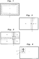
- the in Fig. 2 The image areas 1a and 1b shown correspond to the fields of vision II or IV required by law in ECE Directive R 46 or the fields of vision V or VI or another combination of the fields of vision prescribed by law.
- the calculation unit 20 is adapted to modify the image to be displayed in such a way that a fade-in area 2, 4, 5 (see FIG Figs. 1 to 4 ) is faded in or overlaid in or adjacent to the image area 1, 1a, 1b, 1c, 1d.
- a fade-in area 2, 4, 5 (see FIG Figs. 1 to 4 ) is faded in or overlaid in or adjacent to the image area 1, 1a, 1b, 1c, 1d.
- the embodiment shown is the fade-in area 2, which is faded into the image area 1, a frame around the image area 1.
- the fade-in area 4 is a dividing line between two image areas 1a, 1b.
- the fade-in area 4 is a combination of two dividing lines, a horizontal dividing line and a vertical dividing line, between a total of four image areas 1a, 1b, 1c and 1d.
- the fade-in area 5 is a graphic design, here a figure, which is superimposed on the image to be displayed in an image area 1 and, for example, serves as a warning to the driver of the vehicle as to a person in the vicinity of the vehicle. Combinations of these fade-in areas are possible, so that, for. B. a fade-in area with a graphic design is used as a warning in addition to a frame as a fade-in area 2.
- At least one property of the fade-in area 2, 4, 5, such as the hue, the brightness, the contrast, the saturation or the transparency is dependent on a corresponding property of a measurement area 3 located in the image area 1, 1a, 1b, 1c, 1d , 3a, 3b, 3c, 3d adjusted and fixed.
- the measurement area 3, 3a, 3b, 3c, 3d is preferably directly adjacent to the respective fade-in area 2, 4, 5. This makes it particularly possible to use the information needed to distinguish between fade-in area 2, 4, 5 and image area 1, 1a, 1b, 1c, 1d to define the required properties of the fade-in area 2, 4, 5, so that the fade-in area 2, 4, 5 can be easily recognized and perceived at any time without it assuming properties that are annoying for the driver.
- Areas of the image area 1, 1a, 1b, 1c, 1d further away from the fade-in area 2, 4, 5 are less relevant for the determination of the fade-in area property to be adjusted, since these remote areas are used to distinguish between the fade-in area 2, 4, 5 and the image area 1, 1a, 1b, 1c, 1d are not decisive.
- the property detected by the calculation unit 20 in the measurement area 3, 3a, 3b, 3c, 3d can be a property of hue, brightness, contrast and saturation, or combinations thereof can be used. Furthermore, it is also possible that with several image areas 1a, 1b, 1c, 1d and correspondingly several measurement areas 3a, 3b, 3c, 3d, as in FIG Figs. 2 and 3 shown, the establishment of the properties of the fade-in area 4 is carried out by optimizing the properties measured in the various measurement areas 3a, 3b, 3c, 3d and corresponding assignment of the fade-in area property.
- the image properties of the image area in the measurement area are determined at various points and the fade-in area property is then determined from averaging or optimization. In this way it can be avoided that, for example, a single, random dark point leads to the entire fade-in area property 2 being adapted to a dark image area 1.
- the fade-in area property is determined as a function of a recorded property of the image area 1, 1a, 1b, 1c, 1d, i.e. an image property, and not as a function of parameters recorded outside of the image to be displayed, such as the Brightness around the vehicle. This makes it possible to significantly improve the display on the display unit 30, since the fade-in area property is adapted and optimized with respect to the actual image, that is to say the image property.
- the fade-in area property is optimally determined as a function of a mathematically assigned image property. However, it is not necessary, but possible, that the image property is the same as the fade-in area property that is set:
- a first mathematical function which shows the fade-in area property “brightness” as a function of the image property “brightness”.
- the same image property and fade-in area property are used here.
- the brightness of the image area 1, 1a, 1b, 1c, 1d is recorded and evaluated in the measurement area 3, 3a, 3b, 3c, 3d in the calculation unit 20.
- the fade-in area property “brightness” for the fade-in area 2, 4, 5 is also determined in the calculation unit 20.
- the function can, for example, be a linear function (solid line in Fig.
- a dark fade-in area 2, 4, 5 is assigned to a bright image in measurement area 3, 3a, 3b, 3c, 3d and a light fade-in area 2, 4, 5 is assigned to a dark image area in measurement area 3, 3a, 3b, 3c, 3d. 4, 5 is assigned.
- the function, as in Fig. 5 shown can be linear (solid line in Fig. 5 ) or can be non-linear (dashed lines in Fig. 5 ) or any other function, as long as it enables an unambiguous assignment of at least one image property recorded in the measurement area to at least one fade-in area property.
- a certain corresponding fade-in area property as a function of a certain image property, such as brightness, contrast, saturation or hue (one-to-one assignment, possibly multiple), with the brightness simultaneously depending on, for example the brightness of the image area 1, 1a, 1b, 1c, 1d and the saturation can be changed depending on the saturation of the image area 1, 1a, 1b, 1c, 1d.
- a certain image property such as brightness, contrast, saturation or hue
- a fade-in area property such as transparency
- a specific image property such as, for example, the brightness.
- a light image captured in the measurement area 3, 3a, 3b, 3c has a low transparency of the fade-in area 2, 4, 5 and a dark image captured in the measurement area 3, 3a, 3b, 3c, 3d has a high transparency of the fade-in area 2 , 4, 5 provided.
- any meaningful combinations between the image property and the fade-in area property and corresponding mathematical assignments are possible.
- an image property is preferably determined in each of the measurement areas 3a, 3b, 3c, 3d and in the calculation unit 20 an evaluation is carried out which defines an optimized and / or averaged fade-in area property with regard to the entire recorded image properties.
- the change in the properties of the fade-in area 2, 4, 5 takes place somewhat delayed in time to the changes in the properties of the image area 1, 1a, 1b, 1c.
- the fade-in area property of the fade-in area 2, 4, 5 is preferably only adapted accordingly when a certain property of the image area 1, 1a, 1b, 1c, 1d continues to exist in the measurement area 3, 3a, 3b, 3c, 3d. This avoids a short-term, temporary change in the image property in the measurement area 3, 3a, 3b, 3c, 3d causing a change in the fade-in area property in the fade-in area 2, 4, 5 that is perceived as flickering.
- the display device for a vehicle it is possible to ensure that different image areas can be clearly distinguished independently of the current image properties. Separation areas or overlapping areas can be recognized regardless of the current image content, since the image area and the fade-in area are prevented from assuming the same properties. In addition, it is possible to immediately identify a defective display unit, since, for example, a defective monitor can be distinguished from a black image content at night. Although the image content can be recognized at any time by a clear contrast difference between the image and the fade-in area, the driver can be disturbed by z. B. too bright a fade-in at night can be prevented.
Claims (11)
- Dispositif d'affichage (100) pour un véhicule, avecune unité d'enregistrement (10) pour l'enregistrement de données d'image de l'environnement du véhicule,une unité de calcul (20), etune unité de reproduction (30) pour l'affichage d'une image à représenter avec une zone d'image (1, 1a, 1b, 1c, 1d),dans lequel l'unité de calcul (20) est adaptée pour effectuer une modification des données d'image enregistrées par l'unité d'enregistrement (10) et fournir les données d'image modifiées pour la représentation au niveau de l'unité de reproduction (30),dans lequel la modification contient l'entrée en fondu ou l'enchaînement en fondu d'une zone de fondu (2, 4, 5) dans la zone d'image (1, 1a, 1b, 1c, 1d) de l'image à représenter, dans lequel la zone de fondu (2, 4, 5) se trouve dans ou directement à côté de la zone d'image (1), dans lequel la zone d'image (1, 1a, 1b, 1c, 1d) comporte en outre une zone de mesure (3, 3a, 3b, 3c, 3d) dans laquelle une propriété d'image graphique de la zone d'image (1, 1a, 1b, 1c, 1d) est détectée par une analyse d'image en termes de propriétés graphiques, et dans lequel l'unité de calcul (20) est adaptée pour définir une propriété de zone de fondu graphique en fonction de la propriété d'image graphique détectée, etdans lequel l'unité de calcul (20) est adaptée pour définir la propriété de zone de fondu de manière retardée à partir de la détection de la propriété d'image de la zone d'image lorsqu'une certaine propriété de la zone d'image est présente pendant un certain laps de temps.
- Dispositif d'affichage (100) selon la revendication 1, dans lequel la zone de fondu (2, 4, 5) comprend une zone de séparation (4) entre des zones d'image (1a, 1b, 1c, 1d) et/ou un cadre (2) autour de la zone d'image (1).
- Dispositif d'affichage (100) selon la revendication 1 ou 2, dans lequel la zone de fondu (2, 4, 5) comprend une zone de fondu enchaîné (5) qui recouvre totalement ou au moins partiellement la zone d'image (1).
- Dispositif d'affichage (100) selon l'une quelconque des revendications précédentes, dans lequel la zone de mesure (3, 3a, 3b, 3c, 3d) dans la zone d'image (1, 1a, 1b, 1c, 1d) se trouve dans ou directement à côté de la zone de fondu (2, 4, 5).
- Dispositif d'affichage (100) selon l'une quelconque des revendications précédentes, dans lequel la propriété de zone d'image détectée est une propriété parmi la teinte, la luminosité, le contraste et la saturation ou une combinaison de ces propriétés.
- Dispositif d'affichage (100) selon l'une quelconque des revendications précédentes, dans lequel la propriété de zone de fondu définie est une propriété parmi la teinte, la luminosité, le contraste, la saturation et la transparence ou une combinaison de ces propriétés.
- Dispositif d'affichage (100) selon l'une quelconque des revendications précédentes, dans lequel l'unité de calcul (20) est prévue dans l'unité d'enregistrement (10) et/ou dans l'unité de reproduction (30).
- Dispositif d'affichage (100) selon l'une quelconque des revendications précédentes, dans lequel une unité de traitement (ECU) est en outre prévue et l'unité de calcul (20) est prévue au moins partiellement dans l'unité de traitement (ECU).
- Dispositif d'affichage (100) selon la revendication 8, dans lequel la taille et/ou la position et/ou le type de la zone de fondu (2, 4, 5) sont modifiés en fonction de paramètres de parcours de véhicule actuels.
- Dispositif d'affichage (100) selon l'une quelconque des revendications précédentes, dans lequel sont prévues au moins deux zones d'image (1a, 1b, 1c, 1d) qui sont séparées l'une de l'autre horizontalement et/ou verticalement par la zone de fondu (4).
- Dispositif d'affichage (100) selon l'une quelconque des revendications précédentes, dans lequel l'unité de calcul (20) est adaptée pour représenter la propriété d'image de la zone d'image sur la propriété de zone de fondu au moyen d'une fonction mathématique.
Applications Claiming Priority (1)
| Application Number | Priority Date | Filing Date | Title |
|---|---|---|---|
| DE102015002923.1A DE102015002923B4 (de) | 2015-03-06 | 2015-03-06 | Anzeigeeinrichtung für ein Fahrzeug insbesondere Nutzfahrzeug |
Publications (2)
| Publication Number | Publication Date |
|---|---|
| EP3067237A1 EP3067237A1 (fr) | 2016-09-14 |
| EP3067237B1 true EP3067237B1 (fr) | 2021-12-29 |
Family
ID=55453003
Family Applications (1)
| Application Number | Title | Priority Date | Filing Date |
|---|---|---|---|
| EP16155508.1A Active EP3067237B1 (fr) | 2015-03-06 | 2016-02-12 | Dispositif d'affichage pour véhicule, notamment véhicule utilitaire |
Country Status (5)
| Country | Link |
|---|---|
| US (1) | US10275914B2 (fr) |
| EP (1) | EP3067237B1 (fr) |
| JP (1) | JP6182629B2 (fr) |
| DE (1) | DE102015002923B4 (fr) |
| ES (1) | ES2907999T3 (fr) |
Families Citing this family (8)
| Publication number | Priority date | Publication date | Assignee | Title |
|---|---|---|---|---|
| DE102014210770A1 (de) * | 2014-06-05 | 2015-12-17 | Conti Temic Microelectronic Gmbh | Verfahren und system zur bestimmung einer fahrzeugposition eines fahrzeuges |
| DE102016002470B4 (de) | 2016-02-29 | 2020-10-01 | Mekra Lang Gmbh & Co. Kg | Sichtsystem für ein Fahrzeug, insbesondere Nutzfahrzeug |
| JP6597518B2 (ja) * | 2016-08-15 | 2019-10-30 | 株式会社デンソー | 情報処理装置及びプログラム |
| DE102017210266A1 (de) * | 2017-06-20 | 2018-12-20 | Zf Friedrichshafen Ag | Umfeldüberwachung eines Ego-Fahrzeugs |
| DE102017130566B4 (de) | 2017-12-19 | 2021-07-22 | Mekra Lang Gmbh & Co. Kg | Sichtsystem zur Erfassung einer Fahrzeugumgebung und Spiegelersatzsystem für ein Fahrzeug mit einem Sichtsystem |
| JP6890288B2 (ja) * | 2018-03-28 | 2021-06-18 | パナソニックIpマネジメント株式会社 | 画像処理装置、画像表示システムおよび画像処理方法 |
| CN114567802B (zh) * | 2021-12-29 | 2024-02-09 | 沈阳中科创达软件有限公司 | 一种数据显示方法和装置 |
| CN114633692B (zh) * | 2022-03-14 | 2023-10-03 | 深圳市艾为智能有限公司 | 一种偏心镜头在cms系统中的应用方法 |
Citations (2)
| Publication number | Priority date | Publication date | Assignee | Title |
|---|---|---|---|---|
| US20050174429A1 (en) * | 2004-02-04 | 2005-08-11 | Nissan Motor Co., Ltd. | System for monitoring vehicle surroundings |
| WO2014156788A1 (fr) * | 2013-03-29 | 2014-10-02 | アイシン精機株式会社 | Dispositif de commande d'affichage d'image, système d'affichage d'image et unité d'affichage |
Family Cites Families (17)
| Publication number | Priority date | Publication date | Assignee | Title |
|---|---|---|---|---|
| JP3764317B2 (ja) | 2000-03-02 | 2006-04-05 | 株式会社オートネットワーク技術研究所 | 車載用周辺視認装置 |
| EP1129904B1 (fr) | 2000-03-02 | 2006-08-09 | Autonetworks Technologies, Ltd. | Dispositif de surveillance de zones non-visibles autour de véhicules |
| JP2004173071A (ja) * | 2002-11-21 | 2004-06-17 | Auto Network Gijutsu Kenkyusho:Kk | 車両周辺監視装置 |
| JP4742733B2 (ja) * | 2005-08-05 | 2011-08-10 | 日産自動車株式会社 | 画像つなぎ目処理装置および画像つなぎ目処理方法 |
| JP2007060040A (ja) * | 2005-08-22 | 2007-03-08 | Sanyo Electric Co Ltd | 放送受信装置 |
| DE102006047777A1 (de) | 2006-03-17 | 2007-09-20 | Daimlerchrysler Ag | Virtuelles Spotlight zur Kennzeichnung von interessierenden Objekten in Bilddaten |
| JP4857974B2 (ja) * | 2006-07-13 | 2012-01-18 | トヨタ自動車株式会社 | 車両周辺監視装置 |
| EP1897751B1 (fr) * | 2006-09-11 | 2012-08-15 | Kawasaki Jukogyo Kabushiki Kaisha | Système de conduite assistée pour véhicule |
| JP5120880B2 (ja) * | 2007-10-15 | 2013-01-16 | アルパイン株式会社 | 画像処理装置及び画像処理方法 |
| JP2010215059A (ja) * | 2009-03-16 | 2010-09-30 | Beat Sonic:Kk | 車載用バックカメラアダプター |
| JP5585808B2 (ja) * | 2009-05-22 | 2014-09-10 | アイシン精機株式会社 | 監視装置 |
| JP2011112727A (ja) * | 2009-11-24 | 2011-06-09 | Fujitsu Ltd | 反射型表示装置、および、反射型表示装置の制御回路 |
| US9321399B2 (en) * | 2010-03-01 | 2016-04-26 | Honda Motor Co., Ltd. | Surrounding area monitoring device for vehicle |
| JP5459154B2 (ja) | 2010-09-15 | 2014-04-02 | トヨタ自動車株式会社 | 車両用周囲画像表示装置及び方法 |
| JP5643344B2 (ja) | 2011-01-27 | 2014-12-17 | 京セラ株式会社 | 車両の走行支援装置 |
| US8811670B2 (en) * | 2012-09-28 | 2014-08-19 | The Boeing Company | Method and system for using fingerprints to track moving objects in video |
| JP2015049842A (ja) * | 2013-09-04 | 2015-03-16 | トヨタ自動車株式会社 | 注意喚起表示装置及び注意喚起表示方法 |
-
2015
- 2015-03-06 DE DE102015002923.1A patent/DE102015002923B4/de active Active
-
2016
- 2016-02-12 EP EP16155508.1A patent/EP3067237B1/fr active Active
- 2016-02-12 ES ES16155508T patent/ES2907999T3/es active Active
- 2016-02-19 JP JP2016029510A patent/JP6182629B2/ja active Active
- 2016-03-04 US US15/061,436 patent/US10275914B2/en active Active
Patent Citations (3)
| Publication number | Priority date | Publication date | Assignee | Title |
|---|---|---|---|---|
| US20050174429A1 (en) * | 2004-02-04 | 2005-08-11 | Nissan Motor Co., Ltd. | System for monitoring vehicle surroundings |
| WO2014156788A1 (fr) * | 2013-03-29 | 2014-10-02 | アイシン精機株式会社 | Dispositif de commande d'affichage d'image, système d'affichage d'image et unité d'affichage |
| US20160288717A1 (en) * | 2013-03-29 | 2016-10-06 | Aisin Seiki Kabushiki Kaisha | Image display control apparatus, image display system and display unit |
Also Published As
| Publication number | Publication date |
|---|---|
| DE102015002923B4 (de) | 2023-01-12 |
| EP3067237A1 (fr) | 2016-09-14 |
| US20160260238A1 (en) | 2016-09-08 |
| US10275914B2 (en) | 2019-04-30 |
| JP6182629B2 (ja) | 2017-08-16 |
| ES2907999T3 (es) | 2022-04-27 |
| JP2016177274A (ja) | 2016-10-06 |
| DE102015002923A1 (de) | 2016-09-08 |
Similar Documents
| Publication | Publication Date | Title |
|---|---|---|
| EP3067237B1 (fr) | Dispositif d'affichage pour véhicule, notamment véhicule utilitaire | |
| DE10037130B4 (de) | Einpark- und/oder Rangierhilfeeinrichtung für Pkw oder Lkw | |
| DE102012002149B3 (de) | Verfahren zur Visualisierung des Umfelds eines Kraftfahrzeugs und zugehöriges Kraftfahrzeug | |
| EP2484558B1 (fr) | Dispositif d'affichage pour champs de vision d'un véhicule utilitaire | |
| DE102012102508B4 (de) | Justierverfahren und System einer intelligenten Fahrzeugbildgebungsvorrichtung | |
| EP3109096B1 (fr) | Dispositif d'affichage pour véhicules, notamment véhicules utilitaires | |
| DE102016116839A1 (de) | Aktive Detektion und verbesserte Visualisierung näherkommender Fahrzeuge | |
| DE102012025322B4 (de) | Kraftfahrzeug mit Kamera-Monitor-System | |
| DE102017100004A1 (de) | Verfahren zum Bereitstellen von zumindest einer Information aus einem Umgebungsbereich eines Kraftfahrzeugs, Anzeigesystem für ein Kraftfahrzeug, Fahrerassistenzsystem für ein Kraftfahrzeug sowie Kraftfahrzeug | |
| EP1037189B1 (fr) | Procédé d'affichage d'objets pour véhicule | |
| DE102004048185B4 (de) | Verfahren zum Betrieb eines elektronischen Einsichtnahmesystems und Fahrzeug mit einem elektronischen Einsichtnahmesystem | |
| WO2010025792A1 (fr) | Procédé et dispositif permettant de surveiller les alentours d'un véhicule | |
| EP3434523A1 (fr) | Système de vision indirecte pour un véhicule | |
| WO2019063341A1 (fr) | Procédé destiné à détecter une qualité de chaussée d'une chaussée pour un véhicule automobile, système d'assistance à la conduite et véhicule automobile | |
| WO2005028256A2 (fr) | Visualisation de l'angle mort derriere un montant a d'un vehicule | |
| DE102021212088B4 (de) | Rückfahrkamerasystem für ein anhängerkupplungssystem und verfahren zum erzeugen einer darstellung in heckrichtung eines fahrzeuges | |
| DE102013214369B4 (de) | Verfahren und Vorrichtung zur Wiedergabe eines Umgebungsbereichs eines Fahrzeugs | |
| DE102009003220B4 (de) | Verfahren zur Kollisionswarnung sowie Kollisionswarneinrichtung | |
| EP3583488B1 (fr) | Activation automatisée d'un système d'assistance visuelle | |
| EP2555178B1 (fr) | Procédé de détection d'objets placés sur le côté d'un véhicule utilitaire et véhicule utilitaire avec système de détection permettant de réaliser le procédé | |
| DE102012006679A1 (de) | Verfahren zum Erfassen und Darstellen einer Fahrzeugumgebung eines Fahrzeugs | |
| WO2012003945A1 (fr) | Dispositif et procédé pour détecter et représenter sur un affichage l'environnement arrière et/ou latéral d'un véhicule à moteur | |
| DE102016225643A1 (de) | Blickrichtungsabhängiges System zur Anzeige der Umgebung eines Fahrzeuges | |
| DE102017212917B4 (de) | Steuerung eines Kraftfahrzeugs | |
| DE102016002470B4 (de) | Sichtsystem für ein Fahrzeug, insbesondere Nutzfahrzeug |
Legal Events
| Date | Code | Title | Description |
|---|---|---|---|
| PUAI | Public reference made under article 153(3) epc to a published international application that has entered the european phase |
Free format text: ORIGINAL CODE: 0009012 |
|
| 17P | Request for examination filed |
Effective date: 20160212 |
|
| AK | Designated contracting states |
Kind code of ref document: A1 Designated state(s): AL AT BE BG CH CY CZ DE DK EE ES FI FR GB GR HR HU IE IS IT LI LT LU LV MC MK MT NL NO PL PT RO RS SE SI SK SM TR |
|
| AX | Request for extension of the european patent |
Extension state: BA ME |
|
| STAA | Information on the status of an ep patent application or granted ep patent |
Free format text: STATUS: EXAMINATION IS IN PROGRESS |
|
| 17Q | First examination report despatched |
Effective date: 20181024 |
|
| STAA | Information on the status of an ep patent application or granted ep patent |
Free format text: STATUS: EXAMINATION IS IN PROGRESS |
|
| REG | Reference to a national code |
Ref country code: DE Ref legal event code: R079 Ref document number: 502016014304 Country of ref document: DE Free format text: PREVIOUS MAIN CLASS: B60R0001000000 Ipc: G09G0003200000 |
|
| RIC1 | Information provided on ipc code assigned before grant |
Ipc: G09G 3/20 20060101AFI20210909BHEP |
|
| GRAP | Despatch of communication of intention to grant a patent |
Free format text: ORIGINAL CODE: EPIDOSNIGR1 |
|
| STAA | Information on the status of an ep patent application or granted ep patent |
Free format text: STATUS: GRANT OF PATENT IS INTENDED |
|
| INTG | Intention to grant announced |
Effective date: 20211015 |
|
| GRAS | Grant fee paid |
Free format text: ORIGINAL CODE: EPIDOSNIGR3 |
|
| GRAA | (expected) grant |
Free format text: ORIGINAL CODE: 0009210 |
|
| STAA | Information on the status of an ep patent application or granted ep patent |
Free format text: STATUS: THE PATENT HAS BEEN GRANTED |
|
| AK | Designated contracting states |
Kind code of ref document: B1 Designated state(s): AL AT BE BG CH CY CZ DE DK EE ES FI FR GB GR HR HU IE IS IT LI LT LU LV MC MK MT NL NO PL PT RO RS SE SI SK SM TR |
|
| REG | Reference to a national code |
Ref country code: GB Ref legal event code: FG4D Free format text: NOT ENGLISH |
|
| REG | Reference to a national code |
Ref country code: CH Ref legal event code: EP |
|
| REG | Reference to a national code |
Ref country code: DE Ref legal event code: R096 Ref document number: 502016014304 Country of ref document: DE |
|
| REG | Reference to a national code |
Ref country code: AT Ref legal event code: REF Ref document number: 1459275 Country of ref document: AT Kind code of ref document: T Effective date: 20220115 |
|
| REG | Reference to a national code |
Ref country code: IE Ref legal event code: FG4D Free format text: LANGUAGE OF EP DOCUMENT: GERMAN |
|
| REG | Reference to a national code |
Ref country code: NL Ref legal event code: FP |
|
| REG | Reference to a national code |
Ref country code: SE Ref legal event code: TRGR |
|
| REG | Reference to a national code |
Ref country code: LT Ref legal event code: MG9D |
|
| REG | Reference to a national code |
Ref country code: ES Ref legal event code: FG2A Ref document number: 2907999 Country of ref document: ES Kind code of ref document: T3 Effective date: 20220427 |
|
| PG25 | Lapsed in a contracting state [announced via postgrant information from national office to epo] |
Ref country code: RS Free format text: LAPSE BECAUSE OF FAILURE TO SUBMIT A TRANSLATION OF THE DESCRIPTION OR TO PAY THE FEE WITHIN THE PRESCRIBED TIME-LIMIT Effective date: 20211229 Ref country code: LT Free format text: LAPSE BECAUSE OF FAILURE TO SUBMIT A TRANSLATION OF THE DESCRIPTION OR TO PAY THE FEE WITHIN THE PRESCRIBED TIME-LIMIT Effective date: 20211229 Ref country code: FI Free format text: LAPSE BECAUSE OF FAILURE TO SUBMIT A TRANSLATION OF THE DESCRIPTION OR TO PAY THE FEE WITHIN THE PRESCRIBED TIME-LIMIT Effective date: 20211229 Ref country code: BG Free format text: LAPSE BECAUSE OF FAILURE TO SUBMIT A TRANSLATION OF THE DESCRIPTION OR TO PAY THE FEE WITHIN THE PRESCRIBED TIME-LIMIT Effective date: 20220329 |
|
| PG25 | Lapsed in a contracting state [announced via postgrant information from national office to epo] |
Ref country code: NO Free format text: LAPSE BECAUSE OF FAILURE TO SUBMIT A TRANSLATION OF THE DESCRIPTION OR TO PAY THE FEE WITHIN THE PRESCRIBED TIME-LIMIT Effective date: 20220329 Ref country code: LV Free format text: LAPSE BECAUSE OF FAILURE TO SUBMIT A TRANSLATION OF THE DESCRIPTION OR TO PAY THE FEE WITHIN THE PRESCRIBED TIME-LIMIT Effective date: 20211229 Ref country code: HR Free format text: LAPSE BECAUSE OF FAILURE TO SUBMIT A TRANSLATION OF THE DESCRIPTION OR TO PAY THE FEE WITHIN THE PRESCRIBED TIME-LIMIT Effective date: 20211229 Ref country code: GR Free format text: LAPSE BECAUSE OF FAILURE TO SUBMIT A TRANSLATION OF THE DESCRIPTION OR TO PAY THE FEE WITHIN THE PRESCRIBED TIME-LIMIT Effective date: 20220330 |
|
| PG25 | Lapsed in a contracting state [announced via postgrant information from national office to epo] |
Ref country code: SM Free format text: LAPSE BECAUSE OF FAILURE TO SUBMIT A TRANSLATION OF THE DESCRIPTION OR TO PAY THE FEE WITHIN THE PRESCRIBED TIME-LIMIT Effective date: 20211229 Ref country code: SK Free format text: LAPSE BECAUSE OF FAILURE TO SUBMIT A TRANSLATION OF THE DESCRIPTION OR TO PAY THE FEE WITHIN THE PRESCRIBED TIME-LIMIT Effective date: 20211229 Ref country code: RO Free format text: LAPSE BECAUSE OF FAILURE TO SUBMIT A TRANSLATION OF THE DESCRIPTION OR TO PAY THE FEE WITHIN THE PRESCRIBED TIME-LIMIT Effective date: 20211229 Ref country code: PT Free format text: LAPSE BECAUSE OF FAILURE TO SUBMIT A TRANSLATION OF THE DESCRIPTION OR TO PAY THE FEE WITHIN THE PRESCRIBED TIME-LIMIT Effective date: 20220429 Ref country code: EE Free format text: LAPSE BECAUSE OF FAILURE TO SUBMIT A TRANSLATION OF THE DESCRIPTION OR TO PAY THE FEE WITHIN THE PRESCRIBED TIME-LIMIT Effective date: 20211229 Ref country code: CZ Free format text: LAPSE BECAUSE OF FAILURE TO SUBMIT A TRANSLATION OF THE DESCRIPTION OR TO PAY THE FEE WITHIN THE PRESCRIBED TIME-LIMIT Effective date: 20211229 |
|
| PG25 | Lapsed in a contracting state [announced via postgrant information from national office to epo] |
Ref country code: PL Free format text: LAPSE BECAUSE OF FAILURE TO SUBMIT A TRANSLATION OF THE DESCRIPTION OR TO PAY THE FEE WITHIN THE PRESCRIBED TIME-LIMIT Effective date: 20211229 |
|
| PG25 | Lapsed in a contracting state [announced via postgrant information from national office to epo] |
Ref country code: MC Free format text: LAPSE BECAUSE OF FAILURE TO SUBMIT A TRANSLATION OF THE DESCRIPTION OR TO PAY THE FEE WITHIN THE PRESCRIBED TIME-LIMIT Effective date: 20211229 Ref country code: IS Free format text: LAPSE BECAUSE OF FAILURE TO SUBMIT A TRANSLATION OF THE DESCRIPTION OR TO PAY THE FEE WITHIN THE PRESCRIBED TIME-LIMIT Effective date: 20220429 |
|
| REG | Reference to a national code |
Ref country code: DE Ref legal event code: R097 Ref document number: 502016014304 Country of ref document: DE |
|
| REG | Reference to a national code |
Ref country code: CH Ref legal event code: PL |
|
| REG | Reference to a national code |
Ref country code: BE Ref legal event code: MM Effective date: 20220228 |
|
| PG25 | Lapsed in a contracting state [announced via postgrant information from national office to epo] |
Ref country code: LU Free format text: LAPSE BECAUSE OF NON-PAYMENT OF DUE FEES Effective date: 20220212 Ref country code: DK Free format text: LAPSE BECAUSE OF FAILURE TO SUBMIT A TRANSLATION OF THE DESCRIPTION OR TO PAY THE FEE WITHIN THE PRESCRIBED TIME-LIMIT Effective date: 20211229 Ref country code: AL Free format text: LAPSE BECAUSE OF FAILURE TO SUBMIT A TRANSLATION OF THE DESCRIPTION OR TO PAY THE FEE WITHIN THE PRESCRIBED TIME-LIMIT Effective date: 20211229 |
|
| PLBE | No opposition filed within time limit |
Free format text: ORIGINAL CODE: 0009261 |
|
| STAA | Information on the status of an ep patent application or granted ep patent |
Free format text: STATUS: NO OPPOSITION FILED WITHIN TIME LIMIT |
|
| 26N | No opposition filed |
Effective date: 20220930 |
|
| PG25 | Lapsed in a contracting state [announced via postgrant information from national office to epo] |
Ref country code: LI Free format text: LAPSE BECAUSE OF NON-PAYMENT OF DUE FEES Effective date: 20220228 Ref country code: IE Free format text: LAPSE BECAUSE OF NON-PAYMENT OF DUE FEES Effective date: 20220212 Ref country code: CH Free format text: LAPSE BECAUSE OF NON-PAYMENT OF DUE FEES Effective date: 20220228 |
|
| PG25 | Lapsed in a contracting state [announced via postgrant information from national office to epo] |
Ref country code: SI Free format text: LAPSE BECAUSE OF FAILURE TO SUBMIT A TRANSLATION OF THE DESCRIPTION OR TO PAY THE FEE WITHIN THE PRESCRIBED TIME-LIMIT Effective date: 20211229 Ref country code: BE Free format text: LAPSE BECAUSE OF NON-PAYMENT OF DUE FEES Effective date: 20220228 |
|
| REG | Reference to a national code |
Ref country code: AT Ref legal event code: MM01 Ref document number: 1459275 Country of ref document: AT Kind code of ref document: T Effective date: 20220212 |
|
| PG25 | Lapsed in a contracting state [announced via postgrant information from national office to epo] |
Ref country code: AT Free format text: LAPSE BECAUSE OF NON-PAYMENT OF DUE FEES Effective date: 20220212 |
|
| PGFP | Annual fee paid to national office [announced via postgrant information from national office to epo] |
Ref country code: FR Payment date: 20230217 Year of fee payment: 8 Ref country code: ES Payment date: 20230317 Year of fee payment: 8 |
|
| PGFP | Annual fee paid to national office [announced via postgrant information from national office to epo] |
Ref country code: SE Payment date: 20230220 Year of fee payment: 8 Ref country code: IT Payment date: 20230228 Year of fee payment: 8 |
|
| P01 | Opt-out of the competence of the unified patent court (upc) registered |
Effective date: 20230427 |
|
| REG | Reference to a national code |
Ref country code: DE Ref legal event code: R082 Ref document number: 502016014304 Country of ref document: DE Representative=s name: ALPSPITZ IP ALLGAYER UND PARTNER PATENTANWAELT, DE |
|
| PG25 | Lapsed in a contracting state [announced via postgrant information from national office to epo] |
Ref country code: HU Free format text: LAPSE BECAUSE OF FAILURE TO SUBMIT A TRANSLATION OF THE DESCRIPTION OR TO PAY THE FEE WITHIN THE PRESCRIBED TIME-LIMIT; INVALID AB INITIO Effective date: 20160212 |
|
| PGFP | Annual fee paid to national office [announced via postgrant information from national office to epo] |
Ref country code: NL Payment date: 20240220 Year of fee payment: 9 Ref country code: ES Payment date: 20240319 Year of fee payment: 9 |
|
| PG25 | Lapsed in a contracting state [announced via postgrant information from national office to epo] |
Ref country code: MK Free format text: LAPSE BECAUSE OF FAILURE TO SUBMIT A TRANSLATION OF THE DESCRIPTION OR TO PAY THE FEE WITHIN THE PRESCRIBED TIME-LIMIT Effective date: 20211229 Ref country code: CY Free format text: LAPSE BECAUSE OF FAILURE TO SUBMIT A TRANSLATION OF THE DESCRIPTION OR TO PAY THE FEE WITHIN THE PRESCRIBED TIME-LIMIT Effective date: 20211229 |
|
| PGFP | Annual fee paid to national office [announced via postgrant information from national office to epo] |
Ref country code: DE Payment date: 20240216 Year of fee payment: 9 Ref country code: GB Payment date: 20240222 Year of fee payment: 9 |