EP3067237B1 - Display device for a vehicle, in particular a commercial vehicle - Google Patents
Display device for a vehicle, in particular a commercial vehicle Download PDFInfo
- Publication number
- EP3067237B1 EP3067237B1 EP16155508.1A EP16155508A EP3067237B1 EP 3067237 B1 EP3067237 B1 EP 3067237B1 EP 16155508 A EP16155508 A EP 16155508A EP 3067237 B1 EP3067237 B1 EP 3067237B1
- Authority
- EP
- European Patent Office
- Prior art keywords
- image
- area
- characteristic
- fade
- display system
- Prior art date
- Legal status (The legal status is an assumption and is not a legal conclusion. Google has not performed a legal analysis and makes no representation as to the accuracy of the status listed.)
- Active
Links
- 238000004364 calculation method Methods 0.000 claims description 23
- 238000012545 processing Methods 0.000 claims description 6
- 238000007620 mathematical function Methods 0.000 claims description 5
- 230000001419 dependent effect Effects 0.000 claims description 4
- 238000010191 image analysis Methods 0.000 claims description 3
- 238000012986 modification Methods 0.000 claims description 3
- 230000004048 modification Effects 0.000 claims description 3
- 238000005259 measurement Methods 0.000 description 22
- 230000008859 change Effects 0.000 description 9
- 238000001454 recorded image Methods 0.000 description 5
- 230000000875 corresponding effect Effects 0.000 description 4
- 238000012935 Averaging Methods 0.000 description 3
- 230000002950 deficient Effects 0.000 description 2
- 238000013461 design Methods 0.000 description 2
- 238000001514 detection method Methods 0.000 description 2
- 238000011156 evaluation Methods 0.000 description 2
- 238000012886 linear function Methods 0.000 description 2
- 238000000034 method Methods 0.000 description 2
- 230000008569 process Effects 0.000 description 2
- 230000006978 adaptation Effects 0.000 description 1
- 239000003086 colorant Substances 0.000 description 1
- 230000003111 delayed effect Effects 0.000 description 1
- 230000004069 differentiation Effects 0.000 description 1
- 238000005457 optimization Methods 0.000 description 1
- 238000000926 separation method Methods 0.000 description 1
- 239000013589 supplement Substances 0.000 description 1
- 230000007704 transition Effects 0.000 description 1
Images


Classifications
-
- G—PHYSICS
- G06—COMPUTING; CALCULATING OR COUNTING
- G06T—IMAGE DATA PROCESSING OR GENERATION, IN GENERAL
- G06T11/00—2D [Two Dimensional] image generation
- G06T11/60—Editing figures and text; Combining figures or text
-
- G—PHYSICS
- G09—EDUCATION; CRYPTOGRAPHY; DISPLAY; ADVERTISING; SEALS
- G09G—ARRANGEMENTS OR CIRCUITS FOR CONTROL OF INDICATING DEVICES USING STATIC MEANS TO PRESENT VARIABLE INFORMATION
- G09G3/00—Control arrangements or circuits, of interest only in connection with visual indicators other than cathode-ray tubes
- G09G3/20—Control arrangements or circuits, of interest only in connection with visual indicators other than cathode-ray tubes for presentation of an assembly of a number of characters, e.g. a page, by composing the assembly by combination of individual elements arranged in a matrix no fixed position being assigned to or needed to be assigned to the individual characters or partial characters
-
- B—PERFORMING OPERATIONS; TRANSPORTING
- B60—VEHICLES IN GENERAL
- B60R—VEHICLES, VEHICLE FITTINGS, OR VEHICLE PARTS, NOT OTHERWISE PROVIDED FOR
- B60R1/00—Optical viewing arrangements; Real-time viewing arrangements for drivers or passengers using optical image capturing systems, e.g. cameras or video systems specially adapted for use in or on vehicles
- B60R1/20—Real-time viewing arrangements for drivers or passengers using optical image capturing systems, e.g. cameras or video systems specially adapted for use in or on vehicles
- B60R1/22—Real-time viewing arrangements for drivers or passengers using optical image capturing systems, e.g. cameras or video systems specially adapted for use in or on vehicles for viewing an area outside the vehicle, e.g. the exterior of the vehicle
- B60R1/23—Real-time viewing arrangements for drivers or passengers using optical image capturing systems, e.g. cameras or video systems specially adapted for use in or on vehicles for viewing an area outside the vehicle, e.g. the exterior of the vehicle with a predetermined field of view
- B60R1/26—Real-time viewing arrangements for drivers or passengers using optical image capturing systems, e.g. cameras or video systems specially adapted for use in or on vehicles for viewing an area outside the vehicle, e.g. the exterior of the vehicle with a predetermined field of view to the rear of the vehicle
-
- H—ELECTRICITY
- H04—ELECTRIC COMMUNICATION TECHNIQUE
- H04N—PICTORIAL COMMUNICATION, e.g. TELEVISION
- H04N7/00—Television systems
- H04N7/18—Closed-circuit television [CCTV] systems, i.e. systems in which the video signal is not broadcast
- H04N7/183—Closed-circuit television [CCTV] systems, i.e. systems in which the video signal is not broadcast for receiving images from a single remote source
-
- B—PERFORMING OPERATIONS; TRANSPORTING
- B60—VEHICLES IN GENERAL
- B60R—VEHICLES, VEHICLE FITTINGS, OR VEHICLE PARTS, NOT OTHERWISE PROVIDED FOR
- B60R2300/00—Details of viewing arrangements using cameras and displays, specially adapted for use in a vehicle
- B60R2300/30—Details of viewing arrangements using cameras and displays, specially adapted for use in a vehicle characterised by the type of image processing
- B60R2300/304—Details of viewing arrangements using cameras and displays, specially adapted for use in a vehicle characterised by the type of image processing using merged images, e.g. merging camera image with stored images
- B60R2300/305—Details of viewing arrangements using cameras and displays, specially adapted for use in a vehicle characterised by the type of image processing using merged images, e.g. merging camera image with stored images merging camera image with lines or icons
-
- G—PHYSICS
- G09—EDUCATION; CRYPTOGRAPHY; DISPLAY; ADVERTISING; SEALS
- G09G—ARRANGEMENTS OR CIRCUITS FOR CONTROL OF INDICATING DEVICES USING STATIC MEANS TO PRESENT VARIABLE INFORMATION
- G09G2320/00—Control of display operating conditions
- G09G2320/06—Adjustment of display parameters
- G09G2320/0626—Adjustment of display parameters for control of overall brightness
-
- G—PHYSICS
- G09—EDUCATION; CRYPTOGRAPHY; DISPLAY; ADVERTISING; SEALS
- G09G—ARRANGEMENTS OR CIRCUITS FOR CONTROL OF INDICATING DEVICES USING STATIC MEANS TO PRESENT VARIABLE INFORMATION
- G09G2320/00—Control of display operating conditions
- G09G2320/06—Adjustment of display parameters
- G09G2320/066—Adjustment of display parameters for control of contrast
-
- G—PHYSICS
- G09—EDUCATION; CRYPTOGRAPHY; DISPLAY; ADVERTISING; SEALS
- G09G—ARRANGEMENTS OR CIRCUITS FOR CONTROL OF INDICATING DEVICES USING STATIC MEANS TO PRESENT VARIABLE INFORMATION
- G09G2320/00—Control of display operating conditions
- G09G2320/06—Adjustment of display parameters
- G09G2320/0666—Adjustment of display parameters for control of colour parameters, e.g. colour temperature
-
- G—PHYSICS
- G09—EDUCATION; CRYPTOGRAPHY; DISPLAY; ADVERTISING; SEALS
- G09G—ARRANGEMENTS OR CIRCUITS FOR CONTROL OF INDICATING DEVICES USING STATIC MEANS TO PRESENT VARIABLE INFORMATION
- G09G2360/00—Aspects of the architecture of display systems
- G09G2360/14—Detecting light within display terminals, e.g. using a single or a plurality of photosensors
- G09G2360/144—Detecting light within display terminals, e.g. using a single or a plurality of photosensors the light being ambient light
Definitions
- the invention relates to a display device for a vehicle, in particular a commercial vehicle, with the aid of which images of the vehicle environment can be displayed in a vehicle interior, for example a driver's cab of a commercial vehicle, so that they can be viewed by the driver.
- a display device for a vehicle in particular a commercial vehicle
- Such display devices are used, among other things, as mirror replacement systems or in addition to the exterior mirrors of a vehicle, to show the driver the situation around the vehicle in certain driving situations or at any time in the best possible ergonomic way, and thus help to improve road safety by the driver the vehicle has a good overview of the traffic situation around the vehicle and possible dangers.
- Mirror replacement systems and other camera monitor systems or display devices for vehicles are known in the prior art. These usually include a receiving unit, such as B. a camera with which at least one viewing area around the vehicle can be captured and image data can be recorded from the viewing area, a calculation unit that processes the image data and displays it on a display unit, such as a monitor or a projection onto structural vehicle components, provides.
- the recorded fields of vision around the vehicle can, especially if the system is used as a mirror replacement system, also contain fields of vision prescribed by law, which are prescribed for the European area in the ECE directive R 46.
- monitors with what is known as split-screen display, in which several, often different and possibly different images captured by different recording units are displayed on the same monitor in different areas of the monitor.
- the individual image areas on the monitor are separated by dividing lines or dividing areas, which can be one or different colors and are usually one to several pixels wide.
- the display devices known in the prior art it is also possible to change the display, for example the size of an image from a certain recording unit on the display unit, depending on external signals, for example the steering angle or the driving condition of the vehicle, such as for example driving forward or backward. For example, when a steering angle is detected that does not correspond to straight-ahead travel, it is known to enlarge the side area next to the vehicle or to highlight it in some other way.
- dividing lines or warning frames or graphics are faded in or out depending on the driving situation, but not depending on the image properties of the image to be displayed adjacent to the dividing line or the frame or the graphic.
- the image content adjoining, for example, the dividing line or the overlay in terms of properties essentially corresponds to the properties of the dividing line or the overlay, these can no longer be recognized by the driver.
- black dividing lines are used, it is hardly possible to differentiate between the image and the dividing line in images taken at night.
- US 2013/0307985 A1 relates to a driver assistance system in which clearly recognizable guide lines can be superimposed on a recorded image.
- the modified image is displayed on a display unit.
- a color attribute detection means detects the hue or the brightness of the recorded image area on which a guide line is to be superimposed.
- a color combination pattern setting means or a brightness setting means sets a color combination or brightness of the cross-faded guide lines or compares the contrast or brightness of the captured image area with the values of the guide line and sets a changed one if they are similar or identical Color pattern for the guide lines fixed at least in that part of the image in which the contrast or the brightness are identical or similar.
- US 2013/0176329 A1 relates to a vehicle surroundings display system provided with a camera for capturing an image.
- a processing unit superimposes two-color frames on the captured image.
- JP 2001239882 A relates to a vehicle vision system in which different image areas are separated by a two-color line for display.
- US 2009/0102858 A1 relates to a virtual spotlight for the identification of objects of interest in image data.
- the invention is based on the idea that the properties of a fade-in area, which can be, for example, a dividing line between several image areas, a frame around an image area or a fade area in the image area, depending on the currently captured image area and its current properties or depending on the To adapt and change the properties of the image areas adjoining the fade-in area and to define the properties of the fade-in area or the fade-in areas accordingly.
- a fade-in area which can be, for example, a dividing line between several image areas, a frame around an image area or a fade area in the image area, depending on the currently captured image area and its current properties or depending on the To adapt and change the properties of the image areas adjoining the fade-in area and to define the properties of the fade-in area or the fade-in areas accordingly.
- the properties of the fade-in area include all graphic properties that the fade-in or cross-fade can assume. For example, the hue, the brightness, the contrast, the saturation, the transparency or any combination of these properties of the dividing line or the frame or another fade-in area can be changed.
- a measurement area to be provided in the image area to be displayed, which can be selected by a calculation unit depending on the driving situation or vehicle travel parameters or is a defined image area independent of the driving situation and vehicle travel parameters, within which the properties of the image area are recorded by image analysis in terms of graphical properties.
- the properties recorded in the image area can in turn be any graphical property such as hue, brightness, contrast, saturation, transparency or any combination thereof. It is preferably provided that the measurement area is directly adjacent to the imaginary fade-in area, as this can ensure that the measurement in the image area takes place at the points that are relevant for recognizing the transition between the fade-in area and image area, so that a good contrast is provided between the fade-in area and the adjacent image area.
- an image property can be recorded in the image area (e.g. brightness) and, depending on this, one or more fade-in area properties (e.g. brightness and / or saturation) be adjusted.
- a plurality of image properties can be recorded and, depending on this, in a one-to-one assignment or in an assignment of a plurality of image properties to a fade-in area properties, these can be determined.
- the property of the at least one image area is mapped onto the property of the at least one fade-in area by means of a mathematical function.
- a linear or non-linear function can be used.
- the mathematical function can be determined for a fade-in area between the image areas either as a function of a dominating image area of the two image areas or as a function of both image areas, for example by averaging or the like. This in turn offers the possibility of good recognition and differentiation between the image area and the fade-in area at any time, even if there are several image areas.
- the change in the properties of the fade-in area takes place with a time delay or only if a certain property of the image area is present over a certain period of time. In this way it can be avoided that in the event of a brief, temporary change in the property of the image area, for example in the case of a brief darkening, there is a rapid successive change in the properties of the fade-in area, which in turn could confuse the driver.
- the display device is particularly preferably used in connection with a plurality of image areas.
- the fade-in area separates the various image areas z. B. by a horizontal and / or vertical fade-in area.
- the fade-in area can contain a fade-in, for example to warn the driver of an obstacle in one or more of the image areas and / or a frame can be provided around one or more of the image areas as a fade-in area.
- the overlay can also be a graphic and / or textual overlay of menu navigation, for example a general on-board computer and / or an external device.
- the different image areas to be displayed can preferably be changed as a function of a driving situation that is recorded by driving parameters of the vehicle, for example in a central on-board computer.
- the fade-in area can be enlarged or reduced and / or fade-in area properties such as hue, brightness, contrast, saturation and transparency can be changed or adapted to the driving situation.
- the plurality of image areas can be extracted from the image of a single recording unit, such as a camera, for example by means of the computation unit, or they can be provided by images from different recording units.
- the computation unit can furthermore, if required, separate only individual areas within the recorded image data of a respective recording unit, or it can display the entire recording area.
- calculation unit it should be noted that it can be integrated into the recording unit, such as the camera, can be integrated into the display unit, such as the monitor, can be provided as a separate calculation unit, or can be provided as part of a general on-board computer. Furthermore, it is also possible that a combination of several calculation units is used, so that, for example, the selection of the recording area to be displayed is already made in the camera, while the selection of which of the individual image areas is actually displayed in which size and the modification of the fade-in area property and its Determination in a central processing unit, for example an on-board computer, takes place before the image is displayed on the display unit.
- a central processing unit for example an on-board computer
- a display device 100 for a vehicle contains a recording unit 10, which can be, for example, a camera or an image sensor, a calculation unit 20 and a display unit 30.
- the calculation unit 20 can be integrated into the camera 10, can be integrated into the display unit 30, or, as in FIG Fig. 7 shown, be provided as a separate unit 20, for example in the context of an on-board computer with a processing unit (ECU).
- vehicle travel parameters from various vehicle sensors 40 can also be fed into the computation unit 20, which record characteristic properties of the travel status of the vehicle, such as the speed of the vehicle and the direction of travel , a steering angle, the setting of a direction indicator and the like.
- recording units 10 can be provided around the vehicle, for example one recording unit 10 that detects the side area next to the vehicle on a left side, one recording unit 10 that detects the side area of the vehicle on a right side of the vehicle , a recording unit for the area in front of the vehicle, a recording unit for the area behind the vehicle, and so on.
- the display unit 30 is provided in the form of a monitor, which is attached, for example, in the driver's cab of a utility vehicle at a position easily visible to the driver.
- the display unit 30 could also be provided in the form of a projection device onto a vehicle structural component, likewise easily visible to the driver of the vehicle.
- the display device 100 can be provided overall as a mirror replacement system, which means that the mirrors, which are usually arranged in and around a vehicle, are used to monitor the area around the vehicle and to view areas around the vehicle that cannot be seen by the driver directly, are completely replaced by the camera monitor system or the display device 100.
- the display of the viewing areas or the legally prescribed fields of view is permanent, that is, not interrupted by other displays, and takes place in real time.
- the display device 100 can also serve as a supplement to conventional mirrors or conventional devices for indirect viewing. In this case, the permanent display is unnecessary. Rather, a display can then only take place when a specific driving situation is present.
- the image data of the vehicle surroundings recorded by the recording unit 10 or the recording units 10 are passed to the calculation unit 20 for further processing.
- Calculation unit 20 can, for example, use the data recorded by vehicle sensors 40 to determine a driving state of the vehicle and, depending on this, basically select image areas 1, 1a, 1b, 1c, 1d to be displayed on display unit 30.
- An image area or several image areas, which are contiguous or separate from one another, can be selected by the calculation unit 20, e.g. B. when detecting a turning process z. B. by a steering angle sensor as a vehicle sensor 40 an area in the vicinity of the vehicle one of the selected Image areas 1, 1a, 1b, 1c, 1d.
- the in Fig. 2 The image areas 1a and 1b shown correspond to the fields of vision II or IV required by law in ECE Directive R 46 or the fields of vision V or VI or another combination of the fields of vision prescribed by law.
- the calculation unit 20 is adapted to modify the image to be displayed in such a way that a fade-in area 2, 4, 5 (see FIG Figs. 1 to 4 ) is faded in or overlaid in or adjacent to the image area 1, 1a, 1b, 1c, 1d.
- a fade-in area 2, 4, 5 (see FIG Figs. 1 to 4 ) is faded in or overlaid in or adjacent to the image area 1, 1a, 1b, 1c, 1d.
- the embodiment shown is the fade-in area 2, which is faded into the image area 1, a frame around the image area 1.
- the fade-in area 4 is a dividing line between two image areas 1a, 1b.
- the fade-in area 4 is a combination of two dividing lines, a horizontal dividing line and a vertical dividing line, between a total of four image areas 1a, 1b, 1c and 1d.
- the fade-in area 5 is a graphic design, here a figure, which is superimposed on the image to be displayed in an image area 1 and, for example, serves as a warning to the driver of the vehicle as to a person in the vicinity of the vehicle. Combinations of these fade-in areas are possible, so that, for. B. a fade-in area with a graphic design is used as a warning in addition to a frame as a fade-in area 2.
- At least one property of the fade-in area 2, 4, 5, such as the hue, the brightness, the contrast, the saturation or the transparency is dependent on a corresponding property of a measurement area 3 located in the image area 1, 1a, 1b, 1c, 1d , 3a, 3b, 3c, 3d adjusted and fixed.
- the measurement area 3, 3a, 3b, 3c, 3d is preferably directly adjacent to the respective fade-in area 2, 4, 5. This makes it particularly possible to use the information needed to distinguish between fade-in area 2, 4, 5 and image area 1, 1a, 1b, 1c, 1d to define the required properties of the fade-in area 2, 4, 5, so that the fade-in area 2, 4, 5 can be easily recognized and perceived at any time without it assuming properties that are annoying for the driver.
- Areas of the image area 1, 1a, 1b, 1c, 1d further away from the fade-in area 2, 4, 5 are less relevant for the determination of the fade-in area property to be adjusted, since these remote areas are used to distinguish between the fade-in area 2, 4, 5 and the image area 1, 1a, 1b, 1c, 1d are not decisive.
- the property detected by the calculation unit 20 in the measurement area 3, 3a, 3b, 3c, 3d can be a property of hue, brightness, contrast and saturation, or combinations thereof can be used. Furthermore, it is also possible that with several image areas 1a, 1b, 1c, 1d and correspondingly several measurement areas 3a, 3b, 3c, 3d, as in FIG Figs. 2 and 3 shown, the establishment of the properties of the fade-in area 4 is carried out by optimizing the properties measured in the various measurement areas 3a, 3b, 3c, 3d and corresponding assignment of the fade-in area property.
- the image properties of the image area in the measurement area are determined at various points and the fade-in area property is then determined from averaging or optimization. In this way it can be avoided that, for example, a single, random dark point leads to the entire fade-in area property 2 being adapted to a dark image area 1.
- the fade-in area property is determined as a function of a recorded property of the image area 1, 1a, 1b, 1c, 1d, i.e. an image property, and not as a function of parameters recorded outside of the image to be displayed, such as the Brightness around the vehicle. This makes it possible to significantly improve the display on the display unit 30, since the fade-in area property is adapted and optimized with respect to the actual image, that is to say the image property.
- the fade-in area property is optimally determined as a function of a mathematically assigned image property. However, it is not necessary, but possible, that the image property is the same as the fade-in area property that is set:
- a first mathematical function which shows the fade-in area property “brightness” as a function of the image property “brightness”.
- the same image property and fade-in area property are used here.
- the brightness of the image area 1, 1a, 1b, 1c, 1d is recorded and evaluated in the measurement area 3, 3a, 3b, 3c, 3d in the calculation unit 20.
- the fade-in area property “brightness” for the fade-in area 2, 4, 5 is also determined in the calculation unit 20.
- the function can, for example, be a linear function (solid line in Fig.
- a dark fade-in area 2, 4, 5 is assigned to a bright image in measurement area 3, 3a, 3b, 3c, 3d and a light fade-in area 2, 4, 5 is assigned to a dark image area in measurement area 3, 3a, 3b, 3c, 3d. 4, 5 is assigned.
- the function, as in Fig. 5 shown can be linear (solid line in Fig. 5 ) or can be non-linear (dashed lines in Fig. 5 ) or any other function, as long as it enables an unambiguous assignment of at least one image property recorded in the measurement area to at least one fade-in area property.
- a certain corresponding fade-in area property as a function of a certain image property, such as brightness, contrast, saturation or hue (one-to-one assignment, possibly multiple), with the brightness simultaneously depending on, for example the brightness of the image area 1, 1a, 1b, 1c, 1d and the saturation can be changed depending on the saturation of the image area 1, 1a, 1b, 1c, 1d.
- a certain image property such as brightness, contrast, saturation or hue
- a fade-in area property such as transparency
- a specific image property such as, for example, the brightness.
- a light image captured in the measurement area 3, 3a, 3b, 3c has a low transparency of the fade-in area 2, 4, 5 and a dark image captured in the measurement area 3, 3a, 3b, 3c, 3d has a high transparency of the fade-in area 2 , 4, 5 provided.
- any meaningful combinations between the image property and the fade-in area property and corresponding mathematical assignments are possible.
- an image property is preferably determined in each of the measurement areas 3a, 3b, 3c, 3d and in the calculation unit 20 an evaluation is carried out which defines an optimized and / or averaged fade-in area property with regard to the entire recorded image properties.
- the change in the properties of the fade-in area 2, 4, 5 takes place somewhat delayed in time to the changes in the properties of the image area 1, 1a, 1b, 1c.
- the fade-in area property of the fade-in area 2, 4, 5 is preferably only adapted accordingly when a certain property of the image area 1, 1a, 1b, 1c, 1d continues to exist in the measurement area 3, 3a, 3b, 3c, 3d. This avoids a short-term, temporary change in the image property in the measurement area 3, 3a, 3b, 3c, 3d causing a change in the fade-in area property in the fade-in area 2, 4, 5 that is perceived as flickering.
- the display device for a vehicle it is possible to ensure that different image areas can be clearly distinguished independently of the current image properties. Separation areas or overlapping areas can be recognized regardless of the current image content, since the image area and the fade-in area are prevented from assuming the same properties. In addition, it is possible to immediately identify a defective display unit, since, for example, a defective monitor can be distinguished from a black image content at night. Although the image content can be recognized at any time by a clear contrast difference between the image and the fade-in area, the driver can be disturbed by z. B. too bright a fade-in at night can be prevented.
Description
Die Erfindung betrifft eine Anzeigeeinrichtung für ein Fahrzeug, insbesondere ein Nutzfahrzeug, mit Hilfe derer Bilder von der Fahrzeugumgebung in einem Fahrzeuginnenraum, beispielsweise einer Fahrerkabine eines Nutzfahrzeugs, dargestellt werden können, sodass sie durch den Fahrer einsehbar sind. Solche Anzeigeeinrichtungen dienen unter anderem als Spiegelersatzsysteme oder zusätzlich zu den Außenspiegeln eines Fahrzeugs dazu, dem Fahrer die Situation rund um das Fahrzeug in bestimmten Fahrsituationen oder zu jeder Zeit einsehbar und bestmöglich ergonomisch darzustellen, und so dazu beitragen, die Verkehrssicherheit zu verbessern, indem der Fahrer des Fahrzeugs einen guten Überblick über die Verkehrssituation rund um das Fahrzeug und mögliche Gefahren hat.The invention relates to a display device for a vehicle, in particular a commercial vehicle, with the aid of which images of the vehicle environment can be displayed in a vehicle interior, for example a driver's cab of a commercial vehicle, so that they can be viewed by the driver. Such display devices are used, among other things, as mirror replacement systems or in addition to the exterior mirrors of a vehicle, to show the driver the situation around the vehicle in certain driving situations or at any time in the best possible ergonomic way, and thus help to improve road safety by the driver the vehicle has a good overview of the traffic situation around the vehicle and possible dangers.
Spiegelersatzsysteme und andere Kamera-Monitor-Systeme bzw. Anzeigeeinrichtungen für Fahrzeuge sind im Stand der Technik bekannt. Diese beinhalten gewöhnlich eine Aufhahmeeinheit, wie z. B. eine Kamera, mit der zumindest ein Sichtbereich rund um das Fahrzeug erfasst werden kann und Bilddaten von dem Sichtbereich aufgenommen werden können, eine Berechnungseinheit, die die Bilddaten verarbeitet und zur Darstellung auf einer Wiedergabeeinheit, wie beispielsweise einem Monitor oder einer Projektion auf Fahrzeugstrukturbauteile, bereitstellt. Die erfassten Sichtbereiche rund um das Fahrzeug können, insbesondere wenn das System als Spiegelersatzsystem verwendet wird, auch gesetzlich vorgeschriebene Sichtfelder beinhalten, die für den europäischen Raum in der ECE Richtlinie R 46 vorgeschrieben sind.Mirror replacement systems and other camera monitor systems or display devices for vehicles are known in the prior art. These usually include a receiving unit, such as B. a camera with which at least one viewing area around the vehicle can be captured and image data can be recorded from the viewing area, a calculation unit that processes the image data and displays it on a display unit, such as a monitor or a projection onto structural vehicle components, provides. The recorded fields of vision around the vehicle can, especially if the system is used as a mirror replacement system, also contain fields of vision prescribed by law, which are prescribed for the European area in the ECE directive R 46.
Dabei ist es unter anderem auch bekannt, Monitore mit sogenannter Splitscreen-Darstellung zu verwenden, bei der mehrere, oftmals verschiedene und gegebenenfalls von verschiedenen Aufnahmeeinheiten erfasste Bilder auf demselben Monitor in unterschiedlichen Bereichen des Monitors dargestellt werden. Die einzelnen Bildbereiche auf dem Monitor sind dabei durch Trennlinien oder Trennbereiche getrennt, die ein- oder verschiedenfarbig sein können und in der Regel ein bis mehrere Pixel breit sind.It is also known, inter alia, to use monitors with what is known as split-screen display, in which several, often different and possibly different images captured by different recording units are displayed on the same monitor in different areas of the monitor. The individual image areas on the monitor are separated by dividing lines or dividing areas, which can be one or different colors and are usually one to several pixels wide.
In anderen Systemen, die unter anderem auch für sogenannte Fahrerassistenzsysteme verwendet werden, ist es auch bekannt, auf dem Bildbereich Warnrahmen zu überblenden, wenn die Berechnungseinheit durch Bildanalyse in dem aufgenommenem Bild ein Hindernis oder eine Gefahrenstelle erkennt. Somit kann durch das Hervorheben mittels des Warnrahmens der Fahrer vor einer möglichen Gefahr gewarnt werden. Ferner ist es bekannt, auch andere Grafiken, z. B. auch teiltransparente Grafiken, einzublenden.In other systems, which are also used for so-called driver assistance systems, among other things, it is also known to superimpose warning frames on the image area when the computation unit detects an obstacle or a danger point in the recorded image by means of image analysis. The driver can thus be warned of a possible danger by highlighting by means of the warning frame. It is also known to use other graphics, e.g. B. also partially transparent graphics to be displayed.
Bei den im Stand der Technik bekannten Anzeigeeinrichtungen ist es ferner möglich, die Darstellung, beispielsweise in welcher Größe ein Bild von einer bestimmten Aufnahmeeinheit auf der Wiedergabeeinheit wiedergegeben wird, in Abhängigkeit von externen Signalen zu verändern, beispielsweise dem Lenkwinkel oder dem Fahrzustand des Fahrzeugs, wie beispielsweise Vorwärts- oder Rückwärtsfahrt. Beispielsweise ist bei Erfassen eines Lenkwinkels, der nicht der Geradeausfahrt entspricht, bekannt, den Seitenbereich neben dem Fahrzeug vergrößert oder anderweitig hervorgehoben darzustellen.In the case of the display devices known in the prior art, it is also possible to change the display, for example the size of an image from a certain recording unit on the display unit, depending on external signals, for example the steering angle or the driving condition of the vehicle, such as for example driving forward or backward. For example, when a steering angle is detected that does not correspond to straight-ahead travel, it is known to enlarge the side area next to the vehicle or to highlight it in some other way.
Bei den bekannten Anzeigeeinrichtungen erfolgt die Ein- oder Überblendung von Trennlinien oder Warnrahmen bzw. Grafiken zwar gegebenenfalls in Abhängigkeit von der Fahrsituation, nicht jedoch in Abhängigkeit von den Bildeigenschaften des an die Trennlinie oder den Rahmen bzw. die Grafik angrenzenden, darzustellenden Bilds. Dies hat zur Folge, dass dann, wenn der Bildinhalt angrenzend an beispielsweise die Trennlinie oder die Überlagerung in den Eigenschaften im Wesentlichen den Eigenschaften der Trennlinie oder der Überlagerung entspricht, diese vom Fahrer nicht mehr erkannt werden können. So ist beispielsweise wenn schwarze Trennlinien verwendet werden, bei nächtlichen aufgenommenen Bildern kaum noch eine Unterscheidung zwischen Bild und Trennlinie möglich.In the known display devices, dividing lines or warning frames or graphics are faded in or out depending on the driving situation, but not depending on the image properties of the image to be displayed adjacent to the dividing line or the frame or the graphic. As a result, if the image content adjoining, for example, the dividing line or the overlay in terms of properties essentially corresponds to the properties of the dividing line or the overlay, these can no longer be recognized by the driver. For example, if black dividing lines are used, it is hardly possible to differentiate between the image and the dividing line in images taken at night.
Davon ausgehend ist es Aufgabe der Erfindung, eine Anzeigeeinrichtung für ein Fahrzeug, insbesondere für ein Nutzfahrzeug, bereitzustellen, mittels derer unabhängig von den Bildeigenschaften des Bildbereichs verschiedene Bildbereiche deutlich erkennbar abgetrennt dargestellt werden können oder mittels derer Überlagerungen im Bildbereich gut erkennbar sind.Based on this, it is the object of the invention to provide a display device for a vehicle, in particular for a commercial vehicle, by means of which different image areas can be shown clearly separated, independently of the image properties of the image area, or by means of which overlays in the image area can be easily recognized.
Diese Aufgabe wird mit einer Anzeigeeinrichtung mit den Merkmalen der Anspruchs 1 gelöst. Bevorzugte Ausführungsformen sind in den abhängigen Ansprüchen angegeben.This object is achieved with a display device having the features of
Der Erfindung liegt der Gedanke zugrunde, die Eigenschaften eines Einblendbereichs, der beispielsweise eine Trennlinie zwischen mehreren Bildbereichen, ein Rahmen um einen Bildbereich oder ein Überblendbereich im Bildbereich sein kann, in Abhängigkeit von dem aktuell erfassten Bildbereich und dessen aktuellen Eigenschaften bzw. in Abhängigkeit von den Eigenschaften der an den Einblendbereich angrenzenden Bildbereiche anzupassen und zu verändern und die Eigenschaften des Einblendbereichs bzw. der Einblendbereiche entsprechend festzulegen.The invention is based on the idea that the properties of a fade-in area, which can be, for example, a dividing line between several image areas, a frame around an image area or a fade area in the image area, depending on the currently captured image area and its current properties or depending on the To adapt and change the properties of the image areas adjoining the fade-in area and to define the properties of the fade-in area or the fade-in areas accordingly.
Mit Eigenschaften des Einblendbereichs sind dabei alle grafischen Eigenschaften umfasst, die die Einblendung bzw. Überblendung annehmen kann. So kann beispielsweise der Farbton, die Helligkeit, der Kontrast, die Sättigung, die Transparenz oder eine beliebige Kombination dieser Eigenschaften von der Trennlinie bzw. dem Rahmen oder einem anderen Einblendbereich verändert werden.The properties of the fade-in area include all graphic properties that the fade-in or cross-fade can assume. For example, the hue, the brightness, the contrast, the saturation, the transparency or any combination of these properties of the dividing line or the frame or another fade-in area can be changed.
Dazu ist es vorgesehen, im darzustellenden Bildbereich, der von einer Berechnungseinheit in Abhängigkeit von der Fahrsituation bzw. Fahrzeugfahrtparameter ausgewählt werden kann oder unabhängig von der Fahrsituation und Fahrzeugfahrtparametern ein festgelegter Bildbereich ist, einen Messbereich vorzusehen, innerhalb dessen die Eigenschaften des Bildbereichs erfasst werden durch Bildanalyse im Hinblick auf die grafischen Eigenschaften. Die im Bildbereich erfassten Eigenschaften können wiederum jede beliebige grafische Eigenschaft, wie beispielsweise Farbton, Helligkeit, Kontrast, Sättigung, Transparenz oder beliebige Kombinationen davon sein. Vorzugsweise ist es dabei vorgesehen, dass der Messbereich unmittelbar angrenzend zum gedachten Einblendbereich ist, da dadurch gewährleistet werden kann, dass die Messung im Bildbereich an den Stellen erfolgt, die für das Erkennen des Übergangs zwischen Einblendbereich und Bildbereich relevant sind, so dass ein guter Kontrast zwischen dem Einblendbereich und dem angrenzenden Bildbereich vorgesehen wird.For this purpose, provision is made for a measurement area to be provided in the image area to be displayed, which can be selected by a calculation unit depending on the driving situation or vehicle travel parameters or is a defined image area independent of the driving situation and vehicle travel parameters, within which the properties of the image area are recorded by image analysis in terms of graphical properties. The properties recorded in the image area can in turn be any graphical property such as hue, brightness, contrast, saturation, transparency or any combination thereof. It is preferably provided that the measurement area is directly adjacent to the imaginary fade-in area, as this can ensure that the measurement in the image area takes place at the points that are relevant for recognizing the transition between the fade-in area and image area, so that a good contrast is provided between the fade-in area and the adjacent image area.
Dies ermöglicht es, dass beispielsweise bei Dunkelheit, wenn also der Bildbereich im Wesentlichen dunkler als bei Tageslicht ist, die z. B. zuvor dunkleren Trennlinien z. B. heller dargestellt werden können als bei Helligkeit, so dass einerseits nach wie vor eine gute Erkennbarkeit der Trennlinien und damit der unterschiedlichen Bildbereiche gewährleistet ist und andererseits sichergestellt ist, dass der Fahrer nicht unnötig geblendet wird. Gleichzeitig ist es einfach für den Fahrer zu erkennen, ob die Anzeigeeinrichtung und insbesondere deren Wiedergabeeinheit funktionsfähig ist, da unabhängig von einem gegebenenfalls schwarz erscheinenden Bild zumindest der Einblendbereich jederzeit erkannt werden kann.This makes it possible, for example, in the dark, that is to say when the image area is essentially darker than in daylight, that the z. B. previously darker dividing lines z. B. can be displayed brighter than in the case of brightness, so that on the one hand, the dividing lines and thus the different image areas are still easy to recognize and, on the other hand, it is ensured that the driver is not unnecessarily blinded. At the same time, it is easy for the driver to recognize whether the display device and in particular its display unit is functional, since at least the fade-in area can be recognized at any time regardless of an image that may appear black.
Bezüglich der Anpassung und Festlegung der Eigenschaften des Einblendbereichs im Hinblick auf die des Bildbereichs ist dabei möglichst eine eindeutige Zuordnung zwischen einer oder mehreren Bildeigenschaften zu einer oder mehreren Einblendbereichseigenschaften vorgesehen. Es kann also z. B. eine Bildeigenschaft im Bildbereich erfasst werden (z. B. Helligkeit) und davon abhängig eine oder mehrere Einblendbereichseigenschaften (z. B. Helligkeit und/oder Sättigung) angepasst werden. Alternativ können mehrere Bildeigenschaften erfasst werden und davon Abhängig in einer Eins-zu-eins-Zuordnung oder in einer Zuordnung mehrerer Bildeigenschaften auf eine Einblendbereichseigenschaften diese festgelegt werden.With regard to the adaptation and definition of the properties of the fade-in area with regard to those of the image area, a clear association between one or more image properties and one or more fade-in area properties is provided. So it can z. E.g. an image property can be recorded in the image area (e.g. brightness) and, depending on this, one or more fade-in area properties (e.g. brightness and / or saturation) be adjusted. Alternatively, a plurality of image properties can be recorded and, depending on this, in a one-to-one assignment or in an assignment of a plurality of image properties to a fade-in area properties, these can be determined.
Dabei ist es bevorzugt, dass die Eigenschaft des wenigstens einen Bildbereichs mittels einer mathematischen Funktion auf die Eigenschaft des wenigstens einen Einblendbereichs abgebildet wird. Beispielsweise kann eine lineare oder nicht lineare Funktion verwendet werden.It is preferred that the property of the at least one image area is mapped onto the property of the at least one fade-in area by means of a mathematical function. For example, a linear or non-linear function can be used.
Sind mehrere Bildbereiche vorhanden, so kann für einen zwischen den Bildbereichen liegenden Einblendbereich die mathematische Funktion entweder in Abhängigkeit von einem dominierenden Bildbereich der beiden Bildbereiche oder in Abhängigkeit von beiden Bildbereichen, beispielsweise durch Mittelung oder ähnliches, bestimmt werden. Dies bietet wiederum die Möglichkeit, dass jederzeit, auch bei mehreren Bildbereichen, eine gute Erkennung und Unterscheidung zwischen Bildbereich und Einblendbereich möglich ist.If there are several image areas, the mathematical function can be determined for a fade-in area between the image areas either as a function of a dominating image area of the two image areas or as a function of both image areas, for example by averaging or the like. This in turn offers the possibility of good recognition and differentiation between the image area and the fade-in area at any time, even if there are several image areas.
Ferner ist es möglich, wenn mehrere Einblendbereiche vorgesehen werden, die Eigenschaftsbestimmung des Einblendbereichs für jeden Einblendbereich separat vorzunehmen oder aber eine gemeinsame, wiederum durch Mittelung oder eine mehrdimensionale mathematische Funktion erfolgende Zuordnung vorzunehmen.It is also possible, if several fade-in areas are provided, to determine the properties of the fade-in area separately for each fade-in area or to make a common assignment, again by means of averaging or a multi-dimensional mathematical function.
Ferner erfolgt die Änderung der Eigenschaften des Einblendbereichs zeitlich verzögert bzw. nur dann, wenn über einen bestimmten Zeitraum eine bestimmte Eigenschaft des Bildbereichs vorhanden ist. Dadurch kann vermieden werden, dass bei einer kurzzeitigen, vorübergehenden Änderung der Eigenschaft des Bildbereichs, beispielsweise bei einer kurzen Verdunkelung, eine rasch aufeinanderfolgende Änderung der Eigenschaften des Einblendbereichs erfolgt, was wiederum den Fahrer verwirren könnte.Furthermore, the change in the properties of the fade-in area takes place with a time delay or only if a certain property of the image area is present over a certain period of time. In this way it can be avoided that in the event of a brief, temporary change in the property of the image area, for example in the case of a brief darkening, there is a rapid successive change in the properties of the fade-in area, which in turn could confuse the driver.
Besonders bevorzugt wird die Anzeigeeinrichtung in Verbindung mit mehreren Bildbereichen verwendet. Dabei trennt der Einblendbereich die verschiedenen Bildbereiche z. B. durch einen horizontalen und/oder vertikalen Einblendbereich.The display device is particularly preferably used in connection with a plurality of image areas. The fade-in area separates the various image areas z. B. by a horizontal and / or vertical fade-in area.
Zusätzlich oder alternativ kann, nach Bedarf der Einblendbereich eine Überblendung, beispielsweise zur Warnung des Fahrers vor einem Hindernis in einem oder mehreren der Bildbereiche beinhalten und/oder es kann ein Rahmen um einen oder mehrere der Bildbereiche als Einblendbereich vorgesehen sein. Die Überblendung kann auch eine graphische und/oder textliche Einblendung einer Menüführung z.B. eines allgemeinen Bordcomputers und/oder eines externen Gerätes sein.Additionally or alternatively, if required, the fade-in area can contain a fade-in, for example to warn the driver of an obstacle in one or more of the image areas and / or a frame can be provided around one or more of the image areas as a fade-in area. The overlay can also be a graphic and / or textual overlay of menu navigation, for example a general on-board computer and / or an external device.
Wenn mehrere Bildbereiche vorgesehen sind, können die verschiedenen darzustellenden Bildbereiche bevorzugterweise in Abhängigkeit von einer Fahrsituation, die durch Fahrparameter des Fahrzeugs beispielsweise in einem zentralen Bordcomputer erfasst werden, verändert werden. So kann in Abhängigkeit von einer Fahrsituation beispielsweise eine Vergrößerung oder Verkleinerung des Einblendbereiches stattfinden und/oder können Einblendbereichseigenschaften wie beispielsweise Farbton, Helligkeit, Kontrast, Sättigung und Transparenz geändert bzw. der Fahrsituation angepasst werden.If several image areas are provided, the different image areas to be displayed can preferably be changed as a function of a driving situation that is recorded by driving parameters of the vehicle, for example in a central on-board computer. For example, depending on a driving situation, the fade-in area can be enlarged or reduced and / or fade-in area properties such as hue, brightness, contrast, saturation and transparency can be changed or adapted to the driving situation.
Die mehreren Bildbereiche können beispielsweise mittels der Berechnungseinheit aus dem Bild einer einzigen Aufnahmeeinheit, wie beispielsweise einer Kamera, extrahiert werden, oder sie können durch Bilder verschiedener Aufnahmeeinheiten bereitgestellt werden. Die Berechnungseinheit kann dabei weiterhin nach Bedarf innerhalb der aufgenommenen Bilddaten einer jeweiligen Aufnahmeeinheit nur einzelne Bereiche separieren, oder aber den gesamten Aufnahmebereich darstellen.The plurality of image areas can be extracted from the image of a single recording unit, such as a camera, for example by means of the computation unit, or they can be provided by images from different recording units. The computation unit can furthermore, if required, separate only individual areas within the recorded image data of a respective recording unit, or it can display the entire recording area.
Bezüglich der Berechnungseinheit ist festzuhalten, dass diese in der Aufnahmeeinheit, wie beispielsweise der Kamera integriert sein kann, in der Wiedergabeeinheit, wie beispielsweise dem Monitor integriert sein kann, als separate Berechnungseinheit vorgesehen sein kann oder aber im Rahmen eines allgemeinen Bordcomputers vorgesehen sein kann. Ferner ist es auch möglich, dass eine Kombination von mehreren Berechnungseinheiten verwendet wird, so dass beispielsweise die Auswahl des darzustellenden Aufnahmebereichs bereits in der Kamera erfolgt, während die Auswahl, welcher der einzelnen Bildbereiche tatsächlich in welcher Größe dargestellt wird und die Modifikation der Einblendbereichseigenschaft und deren Festlegung in einer zentralen Verarbeitungseinheit, beispielsweise einem Bordcomputer, erfolgt, ehe das Bild auf der Wiedergabeeinheit angezeigt wird.With regard to the calculation unit, it should be noted that it can be integrated into the recording unit, such as the camera, can be integrated into the display unit, such as the monitor, can be provided as a separate calculation unit, or can be provided as part of a general on-board computer. Furthermore, it is also possible that a combination of several calculation units is used, so that, for example, the selection of the recording area to be displayed is already made in the camera, while the selection of which of the individual image areas is actually displayed in which size and the modification of the fade-in area property and its Determination in a central processing unit, for example an on-board computer, takes place before the image is displayed on the display unit.
Nachfolgend wird die Erfindung beispielhaft anhand der beigefügten Figuren beschrieben, in denen
-
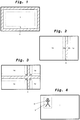
Fig. 1 eine erste Ausführungsform der Darstellung auf einer Wiedergabeeinheit der Anzeigeeinrichtung zeigt; -
Fig. 2 eine weitere Ausführungsform der Darstellung auf der Wiedergabeeinheit der Anzeigeeinrichtung zeigt; -
Fig. 3 noch eine weitere Ausführungsform der Darstellung auf der Wiedergabeeinheit der Anzeigeeinrichtung zeigt; -
Fig. 4 noch eine weitere Ausführungsform der Darstellung auf der Wiedergabeeinheit der Anzeigeeinrichtung zeigt; -
Fig. 5 ein erstes Beispiel für einen mathematischen Zusammenhang zwischen einer im Messbereich gemessenen Bildeigenschaft und der festgelegten Einblendbereichseigenschaft ist; -
Fig. 6 ein zweites Beispiel für einen mathematischen Zusammenhang zwischen einer im Messbereich gemessenen Bildbereichseigenschaft und der Einblendbereichseigenschaft ist; und -
Fig. 7 schematisch eine Anzeigeeinrichtung für ein Fahrzeug zeigt.
-
Fig. 1 shows a first embodiment of the representation on a display unit of the display device; -
Fig. 2 shows a further embodiment of the representation on the display unit of the display device; -
Fig. 3 shows yet another embodiment of the representation on the display unit of the display device; -
Fig. 4 shows yet another embodiment of the representation on the display unit of the display device; -
Fig. 5 is a first example of a mathematical relationship between an image property measured in the measurement area and the specified fade-in area property; -
Fig. 6 is a second example of a mathematical relationship between an image area property measured in the measurement area and the fade-in area property; and -
Fig. 7 shows schematically a display device for a vehicle.
In
Ferner ist zu erwähnen, dass mehrere Aufnahmeeinheiten 10 rund um das Fahrzeug vorgesehen werden können, beispielsweise eine Aufnahmeeinheit 10, die den Seitenbereich neben dem Fahrzeug auf einer linken Seite erfasst, eine Aufnahmeeinheit 10, die den Seitenbereich des Fahrzeugs auf einer rechten Seite des Fahrzeugs erfasst, eine Aufnahmeeinheit für den Bereich vor dem Fahrzeug, eine Aufnahmeeinheit für den Bereich hinter dem Fahrzeug und so weiter.It should also be mentioned that
Die Wiedergabeeinheit 30 ist in Form eines Monitors vorgesehen, der beispielsweise in der Fahrerkabine eines Nutzfahrzeugs an einer gut durch den Fahrer einsehbaren Position angebracht ist. Alternativ könnte die Wiedergabeeinheit 30 auch in Form einer Projektionseinrichtung auf ein Fahrzeugstrukturbauteil, ebenfalls gut durch den Fahrer des Fahrzeugs einsehbar, vorgesehen sein.The
Die Anzeigeeinrichtung 100 kann dabei insgesamt als Spiegelersatzsystem vorgesehen sein, was bedeutet, dass die gewöhnlicherweise in und um ein Fahrzeug angeordneten Spiegel zur Überwachung des Raums um das Fahrzeug und zum Einsehen von Bereichen um das Fahrzeug, die dem Fahrer nicht durch direkte Sicht einsehbar sind, durch das Kameramonitorsystem bzw. die Anzeigeeinrichtung 100 vollständig ersetzt sind. In diesem Fall ist es essentiell, dass die Darstellung der Sichtbereiche bzw. der gesetzlich vorgeschriebenen Sichtfelder dauerhaft, das heißt nicht durch andere Darstellungen zeitlich unterbrochen, und in Echtzeit erfolgt. Andererseits kann die Anzeigeeinrichtung 100 auch als Ergänzung zu herkömmlichen Spiegeln bzw. herkömmlichen Einrichtungen zur indirekten Sicht dienen. In diesem Fall ist die dauerhafte Darstellung entbehrlich. Vielmehr kann dann nur beim Vorliegen einer bestimmten Fahrsituation eine Anzeige erfolgen.The
Die von der Aufnahmeeinheit 10 bzw. den Aufnahmeeinheiten 10 erfassten Bilddaten der Fahrzeugumgebung werden an die Berechnungseinheit 20 zur weiteren Verarbeitung gegeben. Dabei kann die Berechnungseinheit 20 beispielsweise anhand der durch die Fahrzeugsensoren 40 erfassten Daten einen Fahrzustand des Fahrzeugs bestimmen und in Abhängigkeit von diesem grundsätzlich auf der Wiedergabeeinheit 30 darzustellende Bildbereiche 1, 1a, 1b, 1c, 1d auswählen. Dabei kann ein Bildbereich oder es können mehrere Bildbereiche, die zusammenhängend oder voneinander getrennt sind, durch die Berechnungseinheit 20 ausgewählt werden, z. B. kann beim Erfassen eines Abbiegevorgangs z. B. durch einen Lenkwinkelsensor als Fahrzeugsensor 40 ein Bereich im Nahbereich des Fahrzeugs einer der ausgewählten Bildbereiche 1, 1a, 1b, 1c, 1d sein. Des Weiteren können beispielsweise die in
Ferner ist die Berechnungseinheit 20 angepasst, eine Modifikation des darzustellenden Bilds dahingehend vorzunehmen, dass ein Einblendbereich 2, 4, 5 (siehe
Zumindest eine Eigenschaft des Einblendbereichs 2, 4, 5, wie beispielsweise der Farbton, die Helligkeit, der Kontrast, die Sättigung oder die Transparenz wird in Abhängigkeit von einer entsprechenden Eigenschaft eines sich im Bildbereich 1, 1a, 1b, 1c, 1d befindlichen Messbereichs 3, 3a, 3b, 3c, 3d angepasst und festgelegt. Der Messbereich 3, 3a, 3b, 3c, 3d liegt dabei vorzugsweise unmittelbar angrenzend an den jeweiligen Einblendbereich 2, 4, 5. Dadurch ist es besonders gut möglich, die für die Unterscheidung zwischen Einblendbereich 2, 4, 5 und Bildbereich 1, 1a, 1b, 1c, 1d erforderlichen Eigenschaften des Einblendbereichs 2, 4, 5 festzulegen, so dass der Einblendbereich 2, 4, 5 jederzeit gut erkannt und wahrgenommen werden kann, ohne dass er für den Fahrer störende Eigenschaften annimmt. Weiter von dem Einblendbereich 2, 4, 5 entfernt liegende Bereiche des Bildbereichs 1, 1a, 1b, 1c, 1d sind für die Bestimmung der anzupassenden Einblendbereichseigenschaft weniger relevant, da diese entfernt liegenden Bereiche für die Unterscheidung zwischen Einblendbereich 2, 4, 5 und Bildbereich 1, 1a, 1b, 1c, 1d nicht ausschlaggebend sind.At least one property of the fade-in
Die durch die Berechnungseinheit 20 im Messbereich 3, 3a, 3b, 3c, 3d erfasste Eigenschaft kann dabei eine Eigenschaft aus Farbton, Helligkeit, Kontrast und Sättigung sein, oder es können Kombinationen davon verwendet werden. Ferner ist es auch möglich, dass bei mehreren Bildbereichen 1a, 1b, 1c, 1d und entsprechend mehreren Messbereichen 3a, 3b, 3c, 3d, wie in
Auch bei der in
In jedem Fall ist es wesentlich, dass die Einblendbereichseigenschaft in Abhängigkeit von einer erfassten Eigenschaft des Bildbereichs 1, 1a, 1b, 1c, 1d, also einer Bildeigenschaft, bestimmt wird und nicht etwa in Abhängigkeit von außerhalb des darzustellenden Bilds erfassten Parametern, wie beispielsweise der Helligkeit um das Fahrzeug. Dadurch ist es möglich, die Darstellung auf der Wiedergabeeinheit 30 deutlich zu verbessern, da die Einblendbereichseigenschaft bezüglich des tatsächlichen Bilds, also der Bildeigenschaft, angepasst und optimiert ist.In any case, it is essential that the fade-in area property is determined as a function of a recorded property of the
Optimalerweise erfolgt die Festlegung der Einblendbereichseigenschaft in Abhängigkeit von einer mathematisch zugeordneten Bildeigenschaft. Dabei ist es jedoch nicht erforderlich, allerdings möglich, dass die Bildeigenschaft dieselbe ist, wie die Einblendbereichseigenschaft, die festgelegt wird:The fade-in area property is optimally determined as a function of a mathematically assigned image property. However, it is not necessary, but possible, that the image property is the same as the fade-in area property that is set:
In
Alternativ oder ergänzend ist es auch möglich, einer bestimmten Bildeigenschaft, wie beispielsweise der Helligkeit, eine andere Einblendbereichseigenschaft, wie beispielsweise Transparenz, zuzuordnen. Dies ist in
Dabei sind beliebige, sinnvolle Kombinationen zwischen der Bildeigenschaft und der Einblendbereichseigenschaft und entsprechende mathematische Zuordnungen möglich. Wie erwähnt ist es auch möglich, dass mehrere Eigenschaften des Einblendbereichs 2, 4, 5 in Abhängigkeit von einer oder mehreren Bildeigenschaften im Messbereich 3, 3a, 3b, 3c, 3d verändert werden.Any meaningful combinations between the image property and the fade-in area property and corresponding mathematical assignments are possible. As mentioned, it is also possible for several properties of the fade-in
Sind mehrere Messbereiche 3a, 3b, 3c, 3d, an die ein gemeinsamer Einblendbereich 4 angrenzt, vorgesehen, wie es in
Nach einer bevorzugten Ausführungsform erfolgt die Änderung der Eigenschaften des Einblendbereichs 2, 4, 5 zeitlich etwas verzögert zu den Änderungen der Eigenschaften des Bildbereichs 1, 1a, 1b, 1c. Vorzugsweise wird erst bei einem fortgesetzten Vorliegen einer bestimmten Eigenschaft des Bildbereichs 1, 1a, 1b, 1c, 1d im Messbereich 3, 3a, 3b, 3c, 3d die Einblendbereichseigenschaft des Einblendbereichs 2, 4, 5 entsprechend angepasst. Dies vermeidet, dass bei einer kurzfristigen, vorübergehenden Änderung der Bildeigenschaft im Messbereich 3, 3a, 3b, 3c, 3d ein als Flackern empfundenes Verändern der Einblendbereichseigenschaft im Einblendbereich 2, 4, 5 erfolgt.According to a preferred embodiment, the change in the properties of the fade-in
Somit kann mittels der Anzeigeeinrichtung für ein Fahrzeug unabhängig von den aktuellen Bildeigenschaften eine klare Unterscheidbarkeit von verschiedenen Bildbereichen gewährleistet werden. Trennbereiche bzw. Überlagerungsbereiche sind, unabhängig vom aktuellen Bildinhalt, erkennbar, da verhindert wird, dass der Bildbereich und der Einblendbereich die gleichen Eigenschaften annehmen. Zudem ist es möglich, unmittelbar eine defekte Wiedergabeeinheit zu erkennen, da beispielsweise ein defekter Monitor von einem schwarzen Bildinhalt bei Nacht unterschieden werden kann. Wenngleich jederzeit der Bildinhalt durch eine deutliche Kontrastdifferenz zwischen Bild und Einblendbereich erkennbar ist, kann eine Störung des Fahrers durch z. B. eine zu helle Einblendung bei Nacht verhindert werden.Thus, by means of the display device for a vehicle, it is possible to ensure that different image areas can be clearly distinguished independently of the current image properties. Separation areas or overlapping areas can be recognized regardless of the current image content, since the image area and the fade-in area are prevented from assuming the same properties. In addition, it is possible to immediately identify a defective display unit, since, for example, a defective monitor can be distinguished from a black image content at night. Although the image content can be recognized at any time by a clear contrast difference between the image and the fade-in area, the driver can be disturbed by z. B. too bright a fade-in at night can be prevented.
- 1, 1a, 1b, 1c, 1d1, 1a, 1b, 1c, 1d
- BildbereichImage area
- 22
- EinblendbereichFade-in area
- 3, 3a, 3b, 3c, 3d3, 3a, 3b, 3c, 3d
- MessbereichMeasuring range
- 4, 54, 5
- EinblendbereichFade-in area
- 1010
- AufnahmeeinheitRecording unit
- 2020th
- BerechnungseinheitCalculation unit
- 3030th
- WiedergabeeinheitPlayback unit
- 4040
- FahrzeugparametersensorVehicle parameter sensor
- 100100
- AnzeigeeinrichtungDisplay device
Claims (11)
- A display system (100) for a vehicle, comprisinga capturing unit (10) for capturing image data of the vehicle environment,a calculation unit (20), anda display unit (30) for displaying an image to be displayed with an image portion (1, 1a, 1b, 1c, 1d),wherein the calculation unit (20) is adapted to carry out a modification of the image data captured by the capturing unit (10) and to supply the modified image data to the display unit (30) for display,wherein the modification includes overlaying or superimposing an overlay portion (2, 4, 5) on the image portion (1, 1a, 1b, 1c, 1d) of the image to be displayed, the overlay portion (2, 4, 5) being located within or directly adjacent to the image portion (1),wherein the image portion (1, 1a, 1b, 1c, 1d) further includes a measuring portion (3, 3a, 3b, 3c, 3d) where a graphical image characteristic of the image portion (1, 1a, 1b, 1c, 1d) is acquired through image analysis with regard to graphic characteristic, and wherein the calculation unit (20) is adapted to set a graphical overlay portion characteristic dependent on the acquired graphical image characteristic, andwherein the calculation unit (20) is adapted to determine the overlay portion characteristic time-delayed with regard to the acquisition of the image characteristic of the image portion, if a certain characteristic of the image portion is present over a certain period of time.
- The display system (100) according to claim 1, wherein the overlay portion (2, 4, 5) comprises a separating portion (4) between image portions (1a, 1b, 1c, 1d) and/or a frame (2) around the image portion (1).
- The display system (100) according to claim 1 or 2, wherein the overlay portion (2, 4, 5) comprises a superimposition portion (5) which entirely or at least partly overlaps the image portion (1).
- The display system (100) according to one of the preceding claims, wherein the measuring portion (3, 3a, 3b, 3c, 3d) is within or directly adjacent to the overlay portion (2, 4, 5) in the image portion (1, 1a, 1b, 1c, 1d).
- The display system (100) according to one of the preceding claims, wherein the acquired image portion characteristic is a characteristic regarding colour shade, brightness, contrast and saturation, or a combination of these characteristics.
- The display system (100) according to one of the preceding claims, wherein the determined overlay portion characteristic is a characteristic regarding colour shade, brightness, contrast, saturation and transparency, or a combination of these characteristics.
- The display system (100) according to one of the preceding claims, wherein the calculation unit (20) is provided in the capturing unit (10) and/or in the display unit (30).
- The display system (100) according to one of the preceding claims, further comprising a processing unit (ECU) is provided, and wherein the calculation unit (20) is, at least partly, provided in the processing unit (ECU).
- The display system (100) according to claim 8, wherein size and/or position and/or type of the overlay portion (2, 4, 5) are changed dependent on current vehicle driving parameters.
- The display system (100) according to one of the preceding claims, wherein at least two image portions (1a, 1b, 1c, 1d) are provided, which image portions are horizontally and/or vertically separated from each other by the overlay portion (4).
- The display system (100) according to one of the preceding claims, wherein the calculation unit (20) is adapted to map the image characteristic of the image portion to the overlay portion characteristic by means of a mathematical function.
Applications Claiming Priority (1)
| Application Number | Priority Date | Filing Date | Title |
|---|---|---|---|
| DE102015002923.1A DE102015002923B4 (en) | 2015-03-06 | 2015-03-06 | Display device for a vehicle, in particular a commercial vehicle |
Publications (2)
| Publication Number | Publication Date |
|---|---|
| EP3067237A1 EP3067237A1 (en) | 2016-09-14 |
| EP3067237B1 true EP3067237B1 (en) | 2021-12-29 |
Family
ID=55453003
Family Applications (1)
| Application Number | Title | Priority Date | Filing Date |
|---|---|---|---|
| EP16155508.1A Active EP3067237B1 (en) | 2015-03-06 | 2016-02-12 | Display device for a vehicle, in particular a commercial vehicle |
Country Status (5)
| Country | Link |
|---|---|
| US (1) | US10275914B2 (en) |
| EP (1) | EP3067237B1 (en) |
| JP (1) | JP6182629B2 (en) |
| DE (1) | DE102015002923B4 (en) |
| ES (1) | ES2907999T3 (en) |
Families Citing this family (8)
| Publication number | Priority date | Publication date | Assignee | Title |
|---|---|---|---|---|
| DE102014210770A1 (en) * | 2014-06-05 | 2015-12-17 | Conti Temic Microelectronic Gmbh | METHOD AND SYSTEM FOR DETERMINING A VEHICLE POSITION OF A VEHICLE |
| DE102016002470B4 (en) | 2016-02-29 | 2020-10-01 | Mekra Lang Gmbh & Co. Kg | Vision system for a vehicle, in particular a commercial vehicle |
| JP6597518B2 (en) * | 2016-08-15 | 2019-10-30 | 株式会社デンソー | Information processing apparatus and program |
| DE102017210266A1 (en) * | 2017-06-20 | 2018-12-20 | Zf Friedrichshafen Ag | Monitoring the environment of an ego vehicle |
| DE102017130566B4 (en) | 2017-12-19 | 2021-07-22 | Mekra Lang Gmbh & Co. Kg | Vision system for capturing a vehicle environment and a mirror replacement system for a vehicle with a vision system |
| JP6890288B2 (en) * | 2018-03-28 | 2021-06-18 | パナソニックIpマネジメント株式会社 | Image processing equipment, image display system and image processing method |
| CN114567802B (en) * | 2021-12-29 | 2024-02-09 | 沈阳中科创达软件有限公司 | Data display method and device |
| CN114633692B (en) * | 2022-03-14 | 2023-10-03 | 深圳市艾为智能有限公司 | Application method of eccentric lens in CMS system |
Citations (2)
| Publication number | Priority date | Publication date | Assignee | Title |
|---|---|---|---|---|
| US20050174429A1 (en) * | 2004-02-04 | 2005-08-11 | Nissan Motor Co., Ltd. | System for monitoring vehicle surroundings |
| WO2014156788A1 (en) * | 2013-03-29 | 2014-10-02 | アイシン精機株式会社 | Image display control device, image display system, and display unit |
Family Cites Families (17)
| Publication number | Priority date | Publication date | Assignee | Title |
|---|---|---|---|---|
| JP3764317B2 (en) | 2000-03-02 | 2006-04-05 | 株式会社オートネットワーク技術研究所 | In-vehicle peripheral visual recognition device |
| EP1129904B1 (en) | 2000-03-02 | 2006-08-09 | Autonetworks Technologies, Ltd. | Monitoring device of blind zones around vehicles |
| JP2004173071A (en) * | 2002-11-21 | 2004-06-17 | Auto Network Gijutsu Kenkyusho:Kk | Vehicle periphery monitoring device |
| JP4742733B2 (en) * | 2005-08-05 | 2011-08-10 | 日産自動車株式会社 | Image joint processing apparatus and image joint processing method |
| JP2007060040A (en) * | 2005-08-22 | 2007-03-08 | Sanyo Electric Co Ltd | Broadcast receiver |
| DE102006047777A1 (en) * | 2006-03-17 | 2007-09-20 | Daimlerchrysler Ag | Virtual spotlight for marking objects of interest in image data |
| JP4857974B2 (en) * | 2006-07-13 | 2012-01-18 | トヨタ自動車株式会社 | Vehicle periphery monitoring device |
| EP1897751B1 (en) * | 2006-09-11 | 2012-08-15 | Kawasaki Jukogyo Kabushiki Kaisha | Driving assist system for a vehicle |
| JP5120880B2 (en) * | 2007-10-15 | 2013-01-16 | アルパイン株式会社 | Image processing apparatus and image processing method |
| JP2010215059A (en) * | 2009-03-16 | 2010-09-30 | Beat Sonic:Kk | On-vehicle back camera adapter |
| JP5585808B2 (en) * | 2009-05-22 | 2014-09-10 | アイシン精機株式会社 | Monitoring device |
| JP2011112727A (en) | 2009-11-24 | 2011-06-09 | Fujitsu Ltd | Reflective display device and control circuit for the same |
| CN102782740B (en) * | 2010-03-01 | 2015-04-15 | 本田技研工业株式会社 | Surrounding area monitoring device for vehicle |
| JP5459154B2 (en) | 2010-09-15 | 2014-04-02 | トヨタ自動車株式会社 | Vehicle surrounding image display apparatus and method |
| WO2012102392A1 (en) | 2011-01-27 | 2012-08-02 | 京セラ株式会社 | Vehicle driving assist device |
| US8811670B2 (en) * | 2012-09-28 | 2014-08-19 | The Boeing Company | Method and system for using fingerprints to track moving objects in video |
| JP2015049842A (en) * | 2013-09-04 | 2015-03-16 | トヨタ自動車株式会社 | Alert display device and alert display method |
-
2015
- 2015-03-06 DE DE102015002923.1A patent/DE102015002923B4/en active Active
-
2016
- 2016-02-12 EP EP16155508.1A patent/EP3067237B1/en active Active
- 2016-02-12 ES ES16155508T patent/ES2907999T3/en active Active
- 2016-02-19 JP JP2016029510A patent/JP6182629B2/en active Active
- 2016-03-04 US US15/061,436 patent/US10275914B2/en active Active
Patent Citations (3)
| Publication number | Priority date | Publication date | Assignee | Title |
|---|---|---|---|---|
| US20050174429A1 (en) * | 2004-02-04 | 2005-08-11 | Nissan Motor Co., Ltd. | System for monitoring vehicle surroundings |
| WO2014156788A1 (en) * | 2013-03-29 | 2014-10-02 | アイシン精機株式会社 | Image display control device, image display system, and display unit |
| US20160288717A1 (en) * | 2013-03-29 | 2016-10-06 | Aisin Seiki Kabushiki Kaisha | Image display control apparatus, image display system and display unit |
Also Published As
| Publication number | Publication date |
|---|---|
| ES2907999T3 (en) | 2022-04-27 |
| US10275914B2 (en) | 2019-04-30 |
| JP6182629B2 (en) | 2017-08-16 |
| EP3067237A1 (en) | 2016-09-14 |
| DE102015002923B4 (en) | 2023-01-12 |
| JP2016177274A (en) | 2016-10-06 |
| US20160260238A1 (en) | 2016-09-08 |
| DE102015002923A1 (en) | 2016-09-08 |
Similar Documents
| Publication | Publication Date | Title |
|---|---|---|
| EP3067237B1 (en) | Display device for a vehicle, in particular a commercial vehicle | |
| DE10037130B4 (en) | Parking and / or Rangierhilfeeinrichtung for cars or trucks | |
| DE102012002149B3 (en) | Method for visualizing the environment of a motor vehicle and associated motor vehicle | |
| EP2865569B1 (en) | Display device for fields of vision of a commercial vehicle | |
| DE102012102508B4 (en) | Adjustment method and system of a smart vehicle imaging device | |
| EP3109096B1 (en) | Display apparatus for vehicles, in particular for commercial vehicles | |
| DE102016116839A1 (en) | Active detection and improved visualization of approaching vehicles | |
| DE102012025322B4 (en) | Motor vehicle with camera monitor system | |
| DE102017100004A1 (en) | Method for providing at least one information from a surrounding area of a motor vehicle, display system for a motor vehicle, driver assistance system for a motor vehicle and motor vehicle | |
| EP1037189B1 (en) | Method to display objects for vehicle | |
| DE102004048185B4 (en) | Method for operating an electronic inspection system and vehicle with an electronic inspection system | |
| WO2010025792A1 (en) | Method and device for monitoring an environment of a vehicle | |
| EP3434523A1 (en) | Indirect vision system for a vehicle | |
| WO2005028256A2 (en) | Visualisation of the dead angle behind an a-pillar of a vehicle | |
| WO2019063341A1 (en) | Method for detecting a roadway condition of a roadway for a motor vehicle, driver assistance system and motor vehicle | |
| DE102021212088B4 (en) | REAR VIEW CAMERA SYSTEM FOR A TRAILER HITCH SYSTEM AND METHOD FOR GENERATING A REAR DIRECTION OF A VEHICLE | |
| DE102013214369B4 (en) | Method and device for reproducing an area around a vehicle | |
| DE102009003220B4 (en) | Procedure for collision warning and collision warning device | |
| EP3583488B1 (en) | Automated activation of a vision support system | |
| EP2555178A1 (en) | Method for detecting objects to the side of a commercial vehicle and commercial vehicle with a detection system for performing the method | |
| DE102012006679A1 (en) | Method for detecting and displaying vehicle environment of vehicle, involves detecting image of vehicle environment by camera device, where vehicle is moved by retention of driving condition | |
| DE102010033786A1 (en) | Method for detecting and displaying areas laterally and laterally behind a vehicle and vehicle with several image acquisition units for detecting areas located laterally next to and laterally behind the vehicle | |
| DE102016225643A1 (en) | Viewing direction-dependent system for displaying the environment of a vehicle | |
| DE102017212917B4 (en) | control of a motor vehicle | |
| DE102016002470B4 (en) | Vision system for a vehicle, in particular a commercial vehicle |
Legal Events
| Date | Code | Title | Description |
|---|---|---|---|
| PUAI | Public reference made under article 153(3) epc to a published international application that has entered the european phase |
Free format text: ORIGINAL CODE: 0009012 |
|
| 17P | Request for examination filed |
Effective date: 20160212 |
|
| AK | Designated contracting states |
Kind code of ref document: A1 Designated state(s): AL AT BE BG CH CY CZ DE DK EE ES FI FR GB GR HR HU IE IS IT LI LT LU LV MC MK MT NL NO PL PT RO RS SE SI SK SM TR |
|
| AX | Request for extension of the european patent |
Extension state: BA ME |
|
| STAA | Information on the status of an ep patent application or granted ep patent |
Free format text: STATUS: EXAMINATION IS IN PROGRESS |
|
| 17Q | First examination report despatched |
Effective date: 20181024 |
|
| STAA | Information on the status of an ep patent application or granted ep patent |
Free format text: STATUS: EXAMINATION IS IN PROGRESS |
|
| REG | Reference to a national code |
Ref country code: DE Ref legal event code: R079 Ref document number: 502016014304 Country of ref document: DE Free format text: PREVIOUS MAIN CLASS: B60R0001000000 Ipc: G09G0003200000 |
|
| RIC1 | Information provided on ipc code assigned before grant |
Ipc: G09G 3/20 20060101AFI20210909BHEP |
|
| GRAP | Despatch of communication of intention to grant a patent |
Free format text: ORIGINAL CODE: EPIDOSNIGR1 |
|
| STAA | Information on the status of an ep patent application or granted ep patent |
Free format text: STATUS: GRANT OF PATENT IS INTENDED |
|
| INTG | Intention to grant announced |
Effective date: 20211015 |
|
| GRAS | Grant fee paid |
Free format text: ORIGINAL CODE: EPIDOSNIGR3 |
|
| GRAA | (expected) grant |
Free format text: ORIGINAL CODE: 0009210 |
|
| STAA | Information on the status of an ep patent application or granted ep patent |
Free format text: STATUS: THE PATENT HAS BEEN GRANTED |
|
| AK | Designated contracting states |
Kind code of ref document: B1 Designated state(s): AL AT BE BG CH CY CZ DE DK EE ES FI FR GB GR HR HU IE IS IT LI LT LU LV MC MK MT NL NO PL PT RO RS SE SI SK SM TR |
|
| REG | Reference to a national code |
Ref country code: GB Ref legal event code: FG4D Free format text: NOT ENGLISH |
|
| REG | Reference to a national code |
Ref country code: CH Ref legal event code: EP |
|
| REG | Reference to a national code |
Ref country code: DE Ref legal event code: R096 Ref document number: 502016014304 Country of ref document: DE |
|
| REG | Reference to a national code |
Ref country code: AT Ref legal event code: REF Ref document number: 1459275 Country of ref document: AT Kind code of ref document: T Effective date: 20220115 |
|
| REG | Reference to a national code |
Ref country code: IE Ref legal event code: FG4D Free format text: LANGUAGE OF EP DOCUMENT: GERMAN |
|
| REG | Reference to a national code |
Ref country code: NL Ref legal event code: FP |
|
| REG | Reference to a national code |
Ref country code: SE Ref legal event code: TRGR |
|
| REG | Reference to a national code |
Ref country code: LT Ref legal event code: MG9D |
|
| REG | Reference to a national code |
Ref country code: ES Ref legal event code: FG2A Ref document number: 2907999 Country of ref document: ES Kind code of ref document: T3 Effective date: 20220427 |
|
| PG25 | Lapsed in a contracting state [announced via postgrant information from national office to epo] |
Ref country code: RS Free format text: LAPSE BECAUSE OF FAILURE TO SUBMIT A TRANSLATION OF THE DESCRIPTION OR TO PAY THE FEE WITHIN THE PRESCRIBED TIME-LIMIT Effective date: 20211229 Ref country code: LT Free format text: LAPSE BECAUSE OF FAILURE TO SUBMIT A TRANSLATION OF THE DESCRIPTION OR TO PAY THE FEE WITHIN THE PRESCRIBED TIME-LIMIT Effective date: 20211229 Ref country code: FI Free format text: LAPSE BECAUSE OF FAILURE TO SUBMIT A TRANSLATION OF THE DESCRIPTION OR TO PAY THE FEE WITHIN THE PRESCRIBED TIME-LIMIT Effective date: 20211229 Ref country code: BG Free format text: LAPSE BECAUSE OF FAILURE TO SUBMIT A TRANSLATION OF THE DESCRIPTION OR TO PAY THE FEE WITHIN THE PRESCRIBED TIME-LIMIT Effective date: 20220329 |
|
| PG25 | Lapsed in a contracting state [announced via postgrant information from national office to epo] |
Ref country code: NO Free format text: LAPSE BECAUSE OF FAILURE TO SUBMIT A TRANSLATION OF THE DESCRIPTION OR TO PAY THE FEE WITHIN THE PRESCRIBED TIME-LIMIT Effective date: 20220329 Ref country code: LV Free format text: LAPSE BECAUSE OF FAILURE TO SUBMIT A TRANSLATION OF THE DESCRIPTION OR TO PAY THE FEE WITHIN THE PRESCRIBED TIME-LIMIT Effective date: 20211229 Ref country code: HR Free format text: LAPSE BECAUSE OF FAILURE TO SUBMIT A TRANSLATION OF THE DESCRIPTION OR TO PAY THE FEE WITHIN THE PRESCRIBED TIME-LIMIT Effective date: 20211229 Ref country code: GR Free format text: LAPSE BECAUSE OF FAILURE TO SUBMIT A TRANSLATION OF THE DESCRIPTION OR TO PAY THE FEE WITHIN THE PRESCRIBED TIME-LIMIT Effective date: 20220330 |
|
| PG25 | Lapsed in a contracting state [announced via postgrant information from national office to epo] |
Ref country code: SM Free format text: LAPSE BECAUSE OF FAILURE TO SUBMIT A TRANSLATION OF THE DESCRIPTION OR TO PAY THE FEE WITHIN THE PRESCRIBED TIME-LIMIT Effective date: 20211229 Ref country code: SK Free format text: LAPSE BECAUSE OF FAILURE TO SUBMIT A TRANSLATION OF THE DESCRIPTION OR TO PAY THE FEE WITHIN THE PRESCRIBED TIME-LIMIT Effective date: 20211229 Ref country code: RO Free format text: LAPSE BECAUSE OF FAILURE TO SUBMIT A TRANSLATION OF THE DESCRIPTION OR TO PAY THE FEE WITHIN THE PRESCRIBED TIME-LIMIT Effective date: 20211229 Ref country code: PT Free format text: LAPSE BECAUSE OF FAILURE TO SUBMIT A TRANSLATION OF THE DESCRIPTION OR TO PAY THE FEE WITHIN THE PRESCRIBED TIME-LIMIT Effective date: 20220429 Ref country code: EE Free format text: LAPSE BECAUSE OF FAILURE TO SUBMIT A TRANSLATION OF THE DESCRIPTION OR TO PAY THE FEE WITHIN THE PRESCRIBED TIME-LIMIT Effective date: 20211229 Ref country code: CZ Free format text: LAPSE BECAUSE OF FAILURE TO SUBMIT A TRANSLATION OF THE DESCRIPTION OR TO PAY THE FEE WITHIN THE PRESCRIBED TIME-LIMIT Effective date: 20211229 |
|
| PG25 | Lapsed in a contracting state [announced via postgrant information from national office to epo] |
Ref country code: PL Free format text: LAPSE BECAUSE OF FAILURE TO SUBMIT A TRANSLATION OF THE DESCRIPTION OR TO PAY THE FEE WITHIN THE PRESCRIBED TIME-LIMIT Effective date: 20211229 |
|
| PG25 | Lapsed in a contracting state [announced via postgrant information from national office to epo] |
Ref country code: MC Free format text: LAPSE BECAUSE OF FAILURE TO SUBMIT A TRANSLATION OF THE DESCRIPTION OR TO PAY THE FEE WITHIN THE PRESCRIBED TIME-LIMIT Effective date: 20211229 Ref country code: IS Free format text: LAPSE BECAUSE OF FAILURE TO SUBMIT A TRANSLATION OF THE DESCRIPTION OR TO PAY THE FEE WITHIN THE PRESCRIBED TIME-LIMIT Effective date: 20220429 |
|
| REG | Reference to a national code |
Ref country code: DE Ref legal event code: R097 Ref document number: 502016014304 Country of ref document: DE |
|
| REG | Reference to a national code |
Ref country code: CH Ref legal event code: PL |
|
| REG | Reference to a national code |
Ref country code: BE Ref legal event code: MM Effective date: 20220228 |
|
| PG25 | Lapsed in a contracting state [announced via postgrant information from national office to epo] |
Ref country code: LU Free format text: LAPSE BECAUSE OF NON-PAYMENT OF DUE FEES Effective date: 20220212 Ref country code: DK Free format text: LAPSE BECAUSE OF FAILURE TO SUBMIT A TRANSLATION OF THE DESCRIPTION OR TO PAY THE FEE WITHIN THE PRESCRIBED TIME-LIMIT Effective date: 20211229 Ref country code: AL Free format text: LAPSE BECAUSE OF FAILURE TO SUBMIT A TRANSLATION OF THE DESCRIPTION OR TO PAY THE FEE WITHIN THE PRESCRIBED TIME-LIMIT Effective date: 20211229 |
|
| PLBE | No opposition filed within time limit |
Free format text: ORIGINAL CODE: 0009261 |
|
| STAA | Information on the status of an ep patent application or granted ep patent |
Free format text: STATUS: NO OPPOSITION FILED WITHIN TIME LIMIT |
|
| 26N | No opposition filed |
Effective date: 20220930 |
|
| PG25 | Lapsed in a contracting state [announced via postgrant information from national office to epo] |
Ref country code: LI Free format text: LAPSE BECAUSE OF NON-PAYMENT OF DUE FEES Effective date: 20220228 Ref country code: IE Free format text: LAPSE BECAUSE OF NON-PAYMENT OF DUE FEES Effective date: 20220212 Ref country code: CH Free format text: LAPSE BECAUSE OF NON-PAYMENT OF DUE FEES Effective date: 20220228 |
|
| PG25 | Lapsed in a contracting state [announced via postgrant information from national office to epo] |
Ref country code: SI Free format text: LAPSE BECAUSE OF FAILURE TO SUBMIT A TRANSLATION OF THE DESCRIPTION OR TO PAY THE FEE WITHIN THE PRESCRIBED TIME-LIMIT Effective date: 20211229 Ref country code: BE Free format text: LAPSE BECAUSE OF NON-PAYMENT OF DUE FEES Effective date: 20220228 |
|
| PGFP | Annual fee paid to national office [announced via postgrant information from national office to epo] |
Ref country code: NL Payment date: 20230220 Year of fee payment: 8 |
|
| REG | Reference to a national code |
Ref country code: AT Ref legal event code: MM01 Ref document number: 1459275 Country of ref document: AT Kind code of ref document: T Effective date: 20220212 |
|
| PG25 | Lapsed in a contracting state [announced via postgrant information from national office to epo] |
Ref country code: AT Free format text: LAPSE BECAUSE OF NON-PAYMENT OF DUE FEES Effective date: 20220212 |
|
| PGFP | Annual fee paid to national office [announced via postgrant information from national office to epo] |
Ref country code: FR Payment date: 20230217 Year of fee payment: 8 Ref country code: ES Payment date: 20230317 Year of fee payment: 8 |
|
| PGFP | Annual fee paid to national office [announced via postgrant information from national office to epo] |
Ref country code: SE Payment date: 20230220 Year of fee payment: 8 Ref country code: IT Payment date: 20230228 Year of fee payment: 8 Ref country code: GB Payment date: 20230221 Year of fee payment: 8 Ref country code: DE Payment date: 20230214 Year of fee payment: 8 |
|
| P01 | Opt-out of the competence of the unified patent court (upc) registered |
Effective date: 20230427 |
|
| REG | Reference to a national code |
Ref country code: DE Ref legal event code: R082 Ref document number: 502016014304 Country of ref document: DE Representative=s name: ALPSPITZ IP ALLGAYER UND PARTNER PATENTANWAELT, DE |
|
| PG25 | Lapsed in a contracting state [announced via postgrant information from national office to epo] |
Ref country code: HU Free format text: LAPSE BECAUSE OF FAILURE TO SUBMIT A TRANSLATION OF THE DESCRIPTION OR TO PAY THE FEE WITHIN THE PRESCRIBED TIME-LIMIT; INVALID AB INITIO Effective date: 20160212 |
|
| PGFP | Annual fee paid to national office [announced via postgrant information from national office to epo] |
Ref country code: NL Payment date: 20240220 Year of fee payment: 9 Ref country code: ES Payment date: 20240319 Year of fee payment: 9 |