EP3066968B1 - Staubfilterbeutel mit halteplatte - Google Patents
Staubfilterbeutel mit halteplatte Download PDFInfo
- Publication number
- EP3066968B1 EP3066968B1 EP16020050.7A EP16020050A EP3066968B1 EP 3066968 B1 EP3066968 B1 EP 3066968B1 EP 16020050 A EP16020050 A EP 16020050A EP 3066968 B1 EP3066968 B1 EP 3066968B1
- Authority
- EP
- European Patent Office
- Prior art keywords
- bag
- inlet opening
- dust filter
- plastics film
- wall
- Prior art date
- Legal status (The legal status is an assumption and is not a legal conclusion. Google has not performed a legal analysis and makes no representation as to the accuracy of the status listed.)
- Active
Links
Images
Classifications
-
- A—HUMAN NECESSITIES
- A47—FURNITURE; DOMESTIC ARTICLES OR APPLIANCES; COFFEE MILLS; SPICE MILLS; SUCTION CLEANERS IN GENERAL
- A47L—DOMESTIC WASHING OR CLEANING; SUCTION CLEANERS IN GENERAL
- A47L9/00—Details or accessories of suction cleaners, e.g. mechanical means for controlling the suction or for effecting pulsating action; Storing devices specially adapted to suction cleaners or parts thereof; Carrying-vehicles specially adapted for suction cleaners
- A47L9/10—Filters; Dust separators; Dust removal; Automatic exchange of filters
- A47L9/14—Bags or the like; Rigid filtering receptacles; Attachment of, or closures for, bags or receptacles
- A47L9/1427—Means for mounting or attaching bags or filtering receptacles in suction cleaners; Adapters
- A47L9/1436—Connecting plates, e.g. collars, end closures
-
- A—HUMAN NECESSITIES
- A47—FURNITURE; DOMESTIC ARTICLES OR APPLIANCES; COFFEE MILLS; SPICE MILLS; SUCTION CLEANERS IN GENERAL
- A47L—DOMESTIC WASHING OR CLEANING; SUCTION CLEANERS IN GENERAL
- A47L9/00—Details or accessories of suction cleaners, e.g. mechanical means for controlling the suction or for effecting pulsating action; Storing devices specially adapted to suction cleaners or parts thereof; Carrying-vehicles specially adapted for suction cleaners
- A47L9/10—Filters; Dust separators; Dust removal; Automatic exchange of filters
- A47L9/14—Bags or the like; Rigid filtering receptacles; Attachment of, or closures for, bags or receptacles
-
- A—HUMAN NECESSITIES
- A47—FURNITURE; DOMESTIC ARTICLES OR APPLIANCES; COFFEE MILLS; SPICE MILLS; SUCTION CLEANERS IN GENERAL
- A47L—DOMESTIC WASHING OR CLEANING; SUCTION CLEANERS IN GENERAL
- A47L9/00—Details or accessories of suction cleaners, e.g. mechanical means for controlling the suction or for effecting pulsating action; Storing devices specially adapted to suction cleaners or parts thereof; Carrying-vehicles specially adapted for suction cleaners
- A47L9/10—Filters; Dust separators; Dust removal; Automatic exchange of filters
- A47L9/14—Bags or the like; Rigid filtering receptacles; Attachment of, or closures for, bags or receptacles
- A47L9/1427—Means for mounting or attaching bags or filtering receptacles in suction cleaners; Adapters
- A47L9/1436—Connecting plates, e.g. collars, end closures
- A47L9/1445—Connecting plates, e.g. collars, end closures with closure means
Definitions
- the invention relates to a dust filter bag for a vacuum cleaner according to the preamble of claim 1.
- the DE 20 2005 007 503 U1 describes a dust filter bag, in which parts of the filter surface or even one side of the dust filter bag made of an air-impermeable film. This material design should cost savings and increased robustness against abrasive pollution by dust particles in the suction mode.
- the DE 20 2008 004 025 U1 discloses a dust filter bag in which the holding plate is welded by means of a multilayer structure of a film and a layer of an elastic sealing material with the material of the bag wall.
- the DE 10 224 561 A1 describes a dust filter bag, in which a bag-viewing window is formed in the region of the holding plate or on the holding plate, which can detect the level of the filter bag from the outside at high loading.
- Object of the present invention is to provide an improved dust filter bag of the type mentioned.
- the bag wall has a section comprising a plastic film, which consists of a plastic film or which carries a plastic film on a side facing the bag interior and / or on the outside of the bag and / or in an intermediate layer, wherein in this plastic film having a portion of the bag wall, the bag inlet opening is formed. Since the dust filter bag in the region of the support plate has the plastic film having portion, the insertion of the holding plate is facilitated in the device holder of the vacuum cleaner. There is no fear of jamming the bag wall. Thus filter material combinations with large thickness are more applicable.
- the filter surface of the dust filter bag does not have to be substantially reduced in comparison to a conventional dust filter bag which does not have a plastic film section. It is essential that the bag inlet opening is formed directly in the section of the bag wall which has the plastic film and in this case directly in the plastic film. Thus, the area of the inlet opening of the dust filter bag is stabilized particularly well.
- the plastic film having portion of the bag wall has a larger area extent than the holding plate. This ensures a particularly good handling.
- the retaining plate is arranged directly above the section of the bag wall having the plastic film.
- the holding plate on the plastic film having portion of the bag wall is arranged such that the entire part of the underside of the holding plate facing portion of the bag wall as the plastic film having portion of the Bag wall is formed.
- the dust filter bag may be configured such that the portion of the bag wall having the plastic film has an outer perimeter edge that is sealed to an inner perimeter edge of a portion of the bag wall made of filter material.
- the plastic film having portion of the bag wall may be formed as a radially surrounding the bag inlet opening and / or the holding plate inlet opening field, which is welded with its outer boundary edge with one or more filter material consisting of sections or portions of the bag wall.
- the section of the bag wall which has the plastic film and is formed as a field radially surrounding the bag inlet opening and / or the holding plate inlet opening is arranged in a section of a filter material section of the bag wall, the section of the film comprising the plastic film Bag wall has an outer boundary edge which is welded to the boundary edge of the cutout of the filter material portion of the bag wall.
- the dust filter bag is designed as a flat bag.
- the flat bag may be formed from a first layer and a second layer. These two layers are preferably connected to each other at the edge by welding.
- the first layer may comprise the plastic film portion of the bag wall, the bag inlet opening being formed in that portion of the bag wall.
- the second layer may consist of filter material.
- the first layer and the second layer may be formed with congruent, identical, circular or oval or rectangular, preferably square, plan.
- first layer and / or the second layer is or are formed as a single-layer layer or multi-layer layer.
- the dust filter bag 1 for insertion into the receiving space of a vacuum cleaner.
- the dust filter bag 1 comprises a bag 11 with an outer holding plate 12.
- the holding plate 12 has a Garplatteneinlassö réelle 12e (see Fig. 1 ).
- the bag 11 has a bag inlet opening 11e (see Fig. 2 ).
- the holding plate 12 is positioned on the bag on the outside of the bag so that the holding plate inlet opening 12e is aligned with the bag inlet opening 11e (see FIG Figures 1 and 2 ).
- the holding plate inlet opening 12e is formed by the inner edge 14i of an annular rubber seal 14, which is arranged in a central opening of the holding plate by being formed in the region of the opening edge of the central opening of the holding plate with its outer edge (see Fig. 1 ).
- the bag inlet port 11e is formed by the opening edge 111ki of an opening in the bag wall 111.
- the opening edge 111ki of this bag inlet opening is welded to the holding plate 12 to form a ring weld surrounding the bag inlet opening 11e (see FIG Fig. 2 ).
- the inlet openings 11e, 12e are closed in the case of a filter bag 1 not inserted into the vacuum cleaner by a closing flap 13 hinged to the holding plate 12 (see FIG Fig. 2 ).
- the closure flap 13 is acted upon by a spring 15 in the closed position.
- the spring 15 is in spring receptacles on the side facing the inside of the bag Retaining plate 12 and the closure flap 13 is inserted. It is supported at one end of the holder plate side and at the other end on the closure flap (see Fig. 2 ).
- the bag wall 111 in which the bag inlet port 11e is formed has a portion 111k formed of a plastic film (see FIG Fig. 2 ) and a filter material portion 111f.
- the inlet port 11e is formed in the portion 111k formed of the plastic film (see FIG Fig. 2 ).
- the existing of the plastic film portion 111k is inserted in a cutout of the filter material consisting of portion 111f edge connected to each other.
- the outer edge 111ka of the plastic film formed portion 111k is welded to the cutout limiting inner edge 111fi of the filter material portion 111f via an annularly closed weld Sa (see FIG Fig. 2 ).
- the bag inlet port 11e is formed (see FIG Fig. 2 ).
- the annular weld Sa surrounds the bag inlet opening 11e formed in the plastic film of the portion 111k. It is essential that the bag inlet opening 11e is formed exclusively in the plastic-formed section 111k of the bag wall (see FIG Fig. 2 ).
- the weld Sa which connects the filter material-made portion 111f to the plastic-film portion 111k is concentric with the weld Si connecting the plastic-made portion 111k of the bag wall to the support plate 12 (see FIG Fig. 2 ).
- the spacing of the welds Sa and Si varies, since the outer weld Sa has a rectangular course and the inner weld Si has a substantially annular shape.
- the distance between the welds Sa and Si is so large over the entire circumference that the entire surface of the bag facing bottom of the holding plate 12 is disposed within the plastic film 111k enclosed by the outer weld Sa and thus the underside of the holding plate 12 is exclusively on the plastic existing portion 111k of the bag wall for support comes (see Fig. 1 ).
- the plastic film forming the portion 111k of the bag wall 111 is made of a thermoplastic, preferably of the same material as the holding plate 12.
- the filter material is selected such that both the holding plate 12 with the plastic film and the plastic film with the filter material is to be welded , As a welding process, for example, the ultrasonic welding process comes into question.
- the plastic film has a thickness of 30-300 ⁇ m, preferably 100-200 ⁇ m, most preferably between 150 and 180 ⁇ m. It is also possible to glue the plastic film both with the holding plate 12 and with the filter material. It can further be provided that the plastic film 111k is glued to the filter material 111f and is welded to the holding plate 12, or vice versa.
- the dust filter bag 1 may be formed as a flat bag or as another bag type, eg block bottom bag.
- the bag may be formed of a first layer and a second layer. The two layers are welded together at the edges.
- the first layer may support the holding plate 12 and have the plastic film portion 111k of the bag wall 111.
- the first location and the second Location are preferably formed with congruent floor plan and welded circumferentially with a peripheral weld.
- the dust filter bag 1 in the proposed embodiments in the region of the holding plate in each case has no filter material, no jamming due to thick filter material is to be feared when inserting the holding plate 12 in the device holder of the vacuum cleaner.
- filter material combinations with large thickness can be used easily.
Landscapes
- Engineering & Computer Science (AREA)
- Mechanical Engineering (AREA)
- Filters For Electric Vacuum Cleaners (AREA)
Description
- Die Erfindung betrifft einen Staubfilterbeutel für eine Staubsaugeinrichtung nach dem Oberbegriff des Anspruchs 1.
- Die
DE 20 2005 007 503 U1 beschreibt einen Staubfilterbeutel, bei dem Teile der Filterfläche oder auch eine Seite des Staubfilterbeutels aus einer luftundurchlässigen Folie bestehen. Mit dieser Materialgestaltung sollen sich Kosteneinsparungen ergeben sowie eine erhöhte Robustheit gegen abrasive Belastungen durch Staubpartikel im Saugbetrieb. - Die
DE 20 2008 004 025 U1 offenbart einen Staubfilterbeutel, bei dem die Halteplatte mittels eines mehrlagigen Aufbaus aus einer Folie und einer Lage aus einem elastischen Dichtungsmaterial mit dem Material der Beutelwandung verschweißt ist. - Die
DE 10 224 561 A1 beschreibt einen Staubfilterbeutel, bei dem im Bereich der Halteplatte oder an der Halteplatte ein Beutel-Sichtfenster ausgebildet ist, welches bei hohem Beladegrad den Füllstand des Filterbeutels von außen her erkennen lässt. - Aufgabe der vorliegenden Erfindung ist es, einen verbesserten Staubfilterbeutel der genannten Art zu schaffen.
- Erfindungsgemäß wird diese Aufgabe mit dem Gegenstand des Anspruchs 1 gelöst. Es wird damit ein Staubfilterbeutel für eine Staubsaugeinrichtung vorgeschlagen, umfassend
- einen Beutel mit einer Beutelwandung, die zumindest abschnittsweise aus Filtermaterial ausgebildet ist und eine Beuteleinlassöffnung aufweist
- eine Halteplatte, die eine Halteplatteneinlassöffnung aufweist,
- wobei die Halteplatte an der Außenseite des Beutels derart angeordnet ist, dass die Halteplatteneinlassöffnung mit der Beuteleinlassöffnung fluchtet.
- Wesentlich bei der erfindungsgemäßen Lösung ist, dass die Beutelwand einen eine Kunststofffolie aufweisenden Abschnitt aufweist, der aus einer Kunststofffolie besteht oder der an einer dem Beutelinnenraum zugewandten Seite und/oder an der Beutelaußenseite und/oder in einer Zwischenschicht eine Kunststofffolie trägt,
wobei in diesem eine Kunststofffolie aufweisenden Abschnitt der Beutelwand die Beuteleinlassöffnung ausgebildet ist.
Da der Staubfilterbeutel im Bereich der Haltplatte den die Kunststofffolie aufweisenden Abschnitt aufweist, ist das Einschieben der Halteplatte in die Geräteaufnahme der Staubsaugeinrichtung erleichtert. Es ist kein Verklemmen der Beutelwand zu befürchten. Damit sind auch Filtermaterialkombinationen mit großer Dicke eher einsetzbar. Von Vorteil ist es, dass trotz des die Kunststofffolie aufweisenden Abschnitts der Beutelwand die Filterfläche des Staubfilterbeutels gegenüber einem herkömmlichen Staubfilterbeutel, der keinen Kunststofffolienabschnitt aufweist, nicht wesentlich verringert sein muss.
Wesentlich ist, dass die Beuteleinlassöffnung unmittelbar in dem die Kunststofffolie aufweisenden Abschnitt der Beutelwand und dabei unmittelbar in der Kunststofffolie ausgebildet ist. Damit wird der Bereich der Einlassöffnung des Staubfilterbeutels besonders gut stabilisiert. Der die Kunststofffolie aufweisende Abschnitt der Beutelwand weist eine größere Flächenerstreckung auf als die Halteplatte. Dies stellt eine besonders gute Handhabung sicher. Die Halteplatte unmittelbar über dem die Kunststofffolie aufweisenden Abschnitt der Beutelwand angeordnet. Bei entsprechender relativer Flächenerstreckung und Anordnung der Halteplatte einerseits und des die Kunststofffolie aufweisenden Abschnitts der Beutelwand andererseits ist die Halteplatte auf dem die Kunststofffolie aufweisenden Abschnitt der Beutelwand derart angeordnet, dass der gesamte Teil des der Unterseite der Halteplatte zugewandten Abschnitts der Beutelwand als der die Kunststofffolie aufweisende Abschnitt der Beutelwand ausgebildet ist.
Bei bevorzugten Ausführungen kann der Staubfilterbeutel so ausgebildet sein, dass der die Kunststofffolie aufweisende Abschnitt der Beutelwand einen äußeren Begrenzungsrand aufweist, der mit einem inneren Begrenzungsrand eines aus Filtermaterial bestehenden Abschnitts der Beutelwand verschweißt ist.
Der die Kunststofffolie aufweisende Abschnitt der Beutelwand kann als ein die Beuteleinlassöffnung und/oder die Halteplatteneinlassöffnung radial umgebendes Feld ausgebildet sein, das mit seinem äußeren Begrenzungsrand mit einem oder mehreren aus Filtermaterial bestehenden Abschnitt bzw. Abschnitten der Beutelwand verschweißt ist. - Es kann vorgesehen sein, dass der die Kunststofffolie aufweisende Abschnitt der Beutelwand, der als ein die Beuteleinlassöffnung und/oder die Halteplatteneinlassöffnung radial umgebendes Feld ausgebildet ist, in einem Ausschnitt eines aus Filtermaterial bestehenden Abschnitt der Beutelwand angeordnet ist, wobei der die Kunststofffolie aufweisende Abschnitt der Beutelwand einen äußeren Begrenzungsrand aufweist, der mit dem Begrenzungsrand des Ausschnitts des aus Filtermaterial bestehenden Abschnitts der Beutelwand verschweißt ist.
- Es sind bevorzugte Ausführungen möglich, bei denen der Staubfilterbeutel als Flachbeutel ausgebildet ist. Der Flachbeutel kann dabei aus einer ersten Lage und einer zweiten Lage ausgebildet sein. Diese beiden Lagen sind randseitig vorzugsweise durch Verschweißen miteinander verbunden. Die erste Lage kann den aus Kunststofffolie bestehenden Abschnitt der Beutelwand aufweisen, wobei die Beuteleinlassöffnung in diesem Abschnitt der Beutelwand ausgebildet ist. Die zweite Lage kann aus Filtermaterial bestehen.
- Die erste Lage und die zweite Lage können mit deckungsgleichem, identischem, kreisförmigem oder ovalem oder rechteckigem, vorzugsweise quadratischem Grundriss ausgebildet sein.
- Es kann vorgesehen sein, dass die erste Lage und/oder die zweite Lage als einschichtige Lage oder mehrschichtige Lage ausgebildet sind bzw. ist.
- Die Erfindung wird nun anhand von Ausführungsbeispielen näher erläutert. Es zeigen
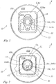
- Fig. 1
- ein Ausführungsbeispiel eines erfindungsgemäßen Staubfilterbeutels, die Halteplatte in der Draufsicht zeigend von außen;
- Fig. 2
- den Staubfilterbeutel in
Fig. 1 in einem Teilschnitt im Bereich der Beutelwand und dabei die Halteplatte in der Rückansicht vom Beutelinnenraum her zeigend. - Bei dem dargestellten Ausführungsbeispiel handelt es sich um einen Staubfilterbeutel 1 zum Einsetzen in den Aufnahmeraum einer Staubsaugeinrichtung. Der Staubfilterbeutel 1 umfasst einen Beutel 11 mit einer außenliegenden Halteplatte 12. Die Halteplatte 12 weist eine Halteplatteneinlassöffnung 12e auf (siehe
Fig. 1 ). Der Beutel 11 weist eine Beuteleinlassöffnung 11e auf (sieheFig. 2 ). Die Halteplatte 12 ist auf dem Beutel auf der Außenseite des Beutels so positioniert, dass die Halteplatteneinlassöffnung 12e mit der Beuteleinlassöffnung 11e fluchtet (sieheFiguren 1 und 2 ). - Die Halteplatteneinlassöffnung 12e wird durch den Innenrand 14i einer ringförmigen Gummidichtung 14 gebildet, die in einer zentralen Öffnung der Halteplatte angeordnet ist, indem sie im Bereich des Öffnungsrandes der zentralen Öffnung der Halteplatte mit ihrem Außenrand angeformt ist (siehe
Fig. 1 ). - Die Beuteleinlassöffnung 11e wird durch den Öffnungsrand 111ki einer Öffnung in der Beutelwand 111 gebildet. Der Öffnungsrand 111ki dieser Beuteleinlassöffnung ist mit der Halteplatte 12 unter Ausbildung einer ringförmig die Beuteleinlassöffnung 11e umgebenden Schweißnaht Si verschweißt (siehe
Fig. 2 ). - Die Einlassöffnungen 11e, 12e sind bei nicht in die Staubsaugeinrichtung eingesetztem Filterbeutel 1 durch eine an der Halteplatte 12 angelenkte Verschlussklappe 13 verschlossen (siehe
Fig. 2 ). Die Verschlussklappe 13 ist durch eine Feder 15 in die Geschlossenstellung beaufschlagt. Die Feder 15 ist in Federaufnahmen an der zur Beutelinnenseite gewandten Seite der Halteplatte 12 und der Verschlussklappe 13 eingesetzt. Sie stützt sich mit ihrem einen Ende halteplattenseitig und mit ihrem anderen Ende an der Verschlussklappe ab (sieheFig. 2 ). - Die Beutelwand 111, in der die Beuteleinlassöffnung 11e ausgebildet ist, weist einen aus einer Kunststofffolie ausgebildeten Abschnitt 111k (siehe
Fig. 2 ) und einen aus Filtermaterial bestehenden Abschnitt 111f auf. Die Einlassöffnung 11e ist in dem aus der Kunststofffolie ausgebildeten Abschnitt 111k ausgebildet (sieheFig. 2 ). - Der aus der Kunststofffolie bestehende Abschnitt 111k ist in einem Ausschnitt des aus Filtermaterial bestehenden Abschnitts 111f randseitig miteinander verbunden eingesetzt angeordnet. Der äußere Rand 111ka des aus Kunststofffolie ausgebildeten Abschnitts 111k ist mit dem den Ausschnitt begrenzenden inneren Rand 111fi des aus Filtermaterial bestehenden Abschnitts 111f über eine ringförmig geschlossene Schweißnaht Sa verschweißt (siehe
Fig. 2 ). - In dem aus Kunststoff ausgebildeten Abschnitt 111k der Beutelwand 111 ist die Beuteleinlassöffnung 11e ausgebildet (siehe
Fig. 2 ). Die ringförmige Schweißnaht Sa umgibt die in der Kunststofffolie des Abschnitts 111k ausgebildete Beuteleinlassöffnung 11e. Wesentlich ist, dass die Beuteleinlassöffnung 11e ausschließlich in dem aus Kunststoff ausgebildeten Abschnitt 111k der Beutelwand ausgebildet ist (sieheFig. 2 ). - Die Schweißnaht Sa, die den aus Filtermaterial bestehenden Abschnitt 111f mit dem aus Kunststofffolie bestehenden Abschnitt 111k verbindet, ist konzentrisch zu der Schweißnaht Si, die den aus Kunststoff bestehenden Abschnitt 111k der Beutelwand mit der Halteplatte 12 verbindet (siehe
Fig. 2 ). Der Abstand der Schweißnähte Sa und Si variiert, da die äußere Schweißnaht Sa rechteckigen Verlauf aufweist und die innere Schweißnaht Si im Wesentlichen kreisringförmigen Verlauf hat. Der Abstand zwischen den Schweißnähten Sa und Si ist über den gesamten Umfangsverlauf so groß, dass die gesamte Fläche der dem Beutel zugewandten Unterseite der Halteplatte 12 innerhalb des von der äußeren Schweißnaht Sa umschlossenen, aus Kunststofffolie bestehenden Abschnitt 111k angeordnet ist und somit die Unterseite der Halteplatte 12 ausschließlich auf dem aus Kunststoff bestehenden Abschnitt 111k der Beutelwand zur Auflage kommt (sieheFig. 1 ). - Die den Abschnitt 111k der Beutelwand 111 bildende Kunststofffolie besteht aus einem Thermoplast, bevorzugt aus dem gleichen Material, wie die Halteplatte 12. Das Filtermaterial ist so gewählt, dass sowohl die Halteplatte 12 mit der Kunststofffolie, als auch die Kunststofffolie mit dem Filtermaterial zu verschweißen ist. Als Schweißverfahren kommt zum Beispiel das Ultraschall-Schweißverfahren in Frage. Die Kunststofffolie hat eine Dicke von 30 - 300 µm, bevorzugt 100 - 200 µm, am meisten bevorzugt zwischen 150 und 180 µm. Es ist auch möglich, die Kunststofffolie sowohl mit der Halteplatte 12 als auch mit dem Filtermaterial zu verkleben. Weiter kann vorgesehen sein, dass die Kunststofffolie 111k mit dem Filtermaterial 111f verklebt ist und mit der Halteplatte 12 verschweißt ist, oder umgekehrt.
- Es hat sich bewährt, folgende Gestaltungsregeln zu befolgen:
- Die Abmessungen der Kunststofffolie 111k sind umlaufend mindestens 10 mm größer als die Halteplatteneinlassöffnung 12e und/oder die Beuteleinlassöffnung 11e zu wählen (siehe
Figuren 1 und 2 ). - Die Abmessungen der Kunststofffolie 111k sind kleiner als eine Fläche, die ca. 50 mm umlaufend um die Kontur der Halteplatte 12 verläuft (siehe
Fig. 1 ). - Die Kunststofffolie 111k ist mit der Außenseite, d. h. mit der Abströmseite des Filtermaterials 111f verbunden.
- Die Befestigung der Kunststofffolie 111k mit dem Filtermaterial 111f ist so gestaltet, beispielsweise durch ein überlappendes Verschweißen, dass am Übergang zwischen der Kunststofffolie und dem Filtermaterial keine Kante entsteht (siehe
Fig. 2 ). - Das Filtermaterial 111f kann die Kunststofffolie 111k im Inneren des Beutels 11 überlappen.
- Die Kunststofffolie 111k kann durchsichtig oder undurchsichtig ausgebildet sein.
- Die Kunststofffolie 111k kann aus einer einschichtigen Folie oder einer mehrschichtigen, coextrudierten Folie ausgebildet sein.
- Der Staubfilterbeutel 1 kann als Flachbeutel oder aber auch als anderer Beuteltyp, z.B. Klotzbodenbeutel, ausgebildet sein. Im Falle des Flachbeutels kann der Beutel aus einer ersten Lage und einer zweiten Lage ausgebildet sein. Die beiden Lagen sind randseitig miteinander verschweißt. Die erste Lage kann die Halteplatte 12 tragen und den aus Kunststofffolie bestehenden Abschnitt 111k der Beutelwand 111 aufweisen. Die erste Lage und die zweite Lage sind vorzugsweise mit deckungsgleichem Grundriss ausgebildet und umlaufend mit einer randseitigen Schweißnaht verschweißt.
- Da der Staubfilterbeutel 1 bei den vorgesehenen Ausführungsbeispielen im Bereich der Halteplatte jeweils kein Filtermaterial aufweist, ist beim Einschieben der Halteplatte 12 in die Geräteaufnahme der Staubsaugeinrichtung kein Verklemmen durch zu dickes Filtermaterial zu befürchten. Damit sind auch Filtermaterialkombinationen mit großer Dicke problemlos einsetzbar.
-
- 1
- Staubfilterbeutel
- 11
- Beutel
- 11e
- Beuteleinlassöffnung
- 12
- Halteplatte
- 12e
- Halteplatteneinlassöffnung = 14i innerer Begrenzungsrand der Dichtung 14
- 13
- Verschlussklappe
- 14
- Dichtung
- 14i
- innerer Begrenzungsrand von 14 = 12e Halteplatteneinlassöffnung
- 15
- Feder
- 111
- Beutelwand
- 111f
- Abschnitt der Beutelwand aus Filtermaterial
- 111fi
- innerer Begrenzungsrand von 111f
- 111k
- Abschnitt der Beutelwand aus Kunststofffolie
- 111ka
- äußerer Begrenzungsrand von 111k
- 111ki
- innerer Begrenzungsrand von 111k = 11e Beuteleinlassöffnung
- Sa
- Verbindungsnaht von 111f und 111k im Bereich 111fi / 111ka
- Si
- Verbindungsnaht von 111k und 12 im Bereich 111ki / 11e
Claims (11)
- Staubfilterbeutel (1) für eine Staubsaugeinrichtung, umfassend- einen Beutel (11) mit einer Beutelwand (111), die zumindest abschnittsweise aus Filtermaterial ausgebildet ist und eine Beuteleinlassöffnung (11e, 111ki) aufweist,- eine Halteplatte (12), die eine Halteplatteneinlassöffnung (12e, 14i) aufweist,- wobei die Halteplatte (12) an der Außenseite des Beutels (11) derart angeordnet ist, dass die Halteplatteneinlassöffnung (12e, 14i) mit der Beuteleinlassöffnung (11e, 111ki, Si) fluchtet,wobei die Beutelwand (111) einen eine Kunststofffolie aufweisenden Abschnitt (111k) aufweist, der aus einer Kunststofffolie besteht, und in diesem eine Kunststofffolie aufweisenden Abschnitt (111k) der Beutelwand (111) die Beuteleinlassöffnung (11e, 111ki, Si) ausgebildet ist,
dadurch gekennzeichnet,
dass der die Kunststofffolie aufweisende Abschnitt (111k) der Beutelwand (111) eine größere Flächenerstreckung aufweist als die Halteplatte (12), sodass der Staubfilterbeutel im Bereich der Halteplatte frei von Filtermaterial ist. - Staubfilterbeutel nach Anspruch 1,
dadurch gekennzeichnet,
dass die Halteplatte (12) auf dem die Kunststofffolie aufweisenden Abschnitt (111k) der Beutelwand (111) derart angeordnet ist, dass der gesamte Teil des der Unterseite der Halteplatte (12) zugewandten Abschnitts der Beutelwand (111) als der die Kunststofffolie aufweisende Abschnitt der Beutelwand (111) ausgebildet ist. - Staubfilterbeutel nach Anspruch 1 oder 2,
dadurch gekennzeichnet,
dass der Öffnungsrand (111ki) der Beuteleinlassöffnung (11e) mit der Halteplatte (12) unter Ausbildung einer ringförmig die Beuteleinlassöffnung (11e) umgebenden Schweißnaht (Si) verschweißt ist - Staubfilterbeutel nach einem der vorangehenden Ansprüche,
dadurch gekennzeichnet,
dass der die Kunststofffolie aufweisende Abschnitt (111k) der Beutelwand (111) einen äußeren Begrenzungsrand (111ka) aufweist, der mit einem inneren Begrenzungsrand (111fi) eines aus Filtermaterial bestehenden Abschnitts (111f) der Beutelwand (111) verschweißt ist. - Staubfilterbeutel nach einem der vorangehenden Ansprüche,
dadurch gekennzeichnet,
dass der die Kunststofffolie aufweisende Abschnitt (111k) der Beutelwand (111) als ein die Beuteleinlassöffnung (11e, 111ki) und/oder die Halteplatteneinlassöffnung (12e, 14i) radial umgebendes Feld ausgebildet ist, das mit seinem äußeren Begrenzungsrand (111ka) mit einem oder mehreren aus Filtermaterial bestehenden Abschnitt (111f) bzw. Abschnitten (111f) der Beutelwand (111) verschweißt ist. - Staubfilterbeutel nach Anspruch 5,
dadurch gekennzeichnet,
dass der die Kunststofffolie aufweisende Abschnitt (111k) der Beutelwand (111), der als ein die Beuteleinlassöffnung (11e, 111ki) und/oder die Halteplatteneinlassöffnung (12e, 14i) radial umgebendes Feld ausgebildet ist, in einem Ausschnitt eines aus Filtermaterial bestehenden Abschnitt (111f) der Beutelwand (111) angeordnet ist, wobei der die Kunststofffolie aufweisende Abschnitt (111k) der Beutelwand (111) einen äußeren Begrenzungsrand (111ka) aufweist, der mit dem Begrenzungsrand (111fi) des Ausschnitts des aus Filtermaterial bestehenden Abschnitts (111f) der Beutelwand (111) verschweißt ist. - Staubfilterbeutel nach einem der vorangehenden Ansprüche,
dadurch gekennzeichnet,
dass der Staubfilterbeutel (1) als Flachbeutel ausgebildet ist, der aus einer ersten Lage und einer zweiten Lage ausgebildet ist, die randseitig miteinander verschweißt sind,- wobei die erste Lage den aus Kunststofffolie bestehenden Abschnitt (111k) der Beutelwand (111) aufweist und dabei die Beuteleinlassöffnung (11e, 111ki) in dem aus Kunststofffolie bestehenden Abschnitt (111k) der Beutelwand (111) ausgebildet ist, und- wobei die zweite Lage aus Filtermaterial besteht. - Staubfilterbeutel nach Anspruch 7,
dadurch gekennzeichnet,
dass die erste Lage und die zweite Lage mit deckungsgleichem, identischem, kreisförmigem oder ovalem oder rechteckigem, vorzugsweise quadratischem Grundriss ausgebildet sind. - Staubfilterbeutel nach einem der Ansprüche 7 oder 8,
dadurch gekennzeichnet,
dass die erste Lage und/oder die zweite Lage als einschichtige Lage oder mehrschichtige Lage ausgebildet sind bzw. ist. - Staubfilterbeutel nach einem der vorangehenden Ansprüche,
dadurch gekennzeichnet,
dass die Kunststofffolie (111k) durchsichtig oder undurchsichtig ausgebildet ist. - Staubfilterbeutel nach einem der vorangehenden Ansprüche,
dadurch gekennzeichnet,
dass die Kunststofffolie (111k) ist mit der Abströmseite des Filtermaterials (111f) verbunden ist.
Applications Claiming Priority (1)
| Application Number | Priority Date | Filing Date | Title |
|---|---|---|---|
| DE102015103515.4A DE102015103515A1 (de) | 2015-03-10 | 2015-03-10 | Staubfilterbeutel für eine Staubsaugeinrichtung |
Publications (2)
| Publication Number | Publication Date |
|---|---|
| EP3066968A1 EP3066968A1 (de) | 2016-09-14 |
| EP3066968B1 true EP3066968B1 (de) | 2017-11-29 |
Family
ID=55484802
Family Applications (1)
| Application Number | Title | Priority Date | Filing Date |
|---|---|---|---|
| EP16020050.7A Active EP3066968B1 (de) | 2015-03-10 | 2016-02-24 | Staubfilterbeutel mit halteplatte |
Country Status (2)
| Country | Link |
|---|---|
| EP (1) | EP3066968B1 (de) |
| DE (1) | DE102015103515A1 (de) |
Cited By (1)
| Publication number | Priority date | Publication date | Assignee | Title |
|---|---|---|---|---|
| DE102021132864A1 (de) | 2021-12-13 | 2023-06-15 | Bachata Stiftung | Recycling-Anschlussflansch für Staubsaugerbeutel und Verfahren zur Herstellung |
Families Citing this family (3)
| Publication number | Priority date | Publication date | Assignee | Title |
|---|---|---|---|---|
| DE102015103515A1 (de) | 2015-03-10 | 2016-09-15 | Branofilter Gmbh | Staubfilterbeutel für eine Staubsaugeinrichtung |
| DE202018102370U1 (de) | 2018-04-27 | 2018-05-04 | Eurofilters Holding N.V. | Staubsaugerfilterbeutel mit Folie im Bereich der Halteplatte |
| EP3560402B1 (de) | 2018-04-27 | 2022-12-07 | Eurofilters Holding N.V. | Staubsaugerfilterbeutel mit folie im bereich der halteplatte |
Family Cites Families (8)
| Publication number | Priority date | Publication date | Assignee | Title |
|---|---|---|---|---|
| DE10224561A1 (de) | 2002-06-03 | 2003-12-11 | Vorwerk Co Interholding | Filterbautel für einen Staubsauger, sowie Staubsauger, insbesondere Haushalts-Staubsauger |
| DE102004030346A1 (de) * | 2004-06-18 | 2006-01-05 | Branofilter Gmbh | Staubfilterbeutel und zugeordnete Adapterplatte |
| DE202005007503U1 (de) | 2005-05-12 | 2006-09-21 | Melitta Haushaltsprodukte Gmbh & Co. Kg | Filterbeutel |
| ATE431095T1 (de) | 2007-08-17 | 2009-05-15 | Eurofilters Holding Nv | Staubsaugerfilterbeutel |
| DE202008004025U1 (de) * | 2008-03-20 | 2009-08-06 | Wolf Pvg Gmbh & Co. Kg | Filter |
| DE102010060353A1 (de) * | 2010-11-04 | 2012-05-10 | Papierverarbeitung Görlitz GmbH | Staubfilterbeutel für Staubsauger |
| DE102012019470B4 (de) * | 2012-10-03 | 2016-02-18 | Elku Bauteile GmbH | Staubbeutel mit einer Saugöffnung mit einem Kragen und einer Verschlussvorrichtung |
| DE102015103515A1 (de) | 2015-03-10 | 2016-09-15 | Branofilter Gmbh | Staubfilterbeutel für eine Staubsaugeinrichtung |
-
2015
- 2015-03-10 DE DE102015103515.4A patent/DE102015103515A1/de not_active Ceased
-
2016
- 2016-02-24 EP EP16020050.7A patent/EP3066968B1/de active Active
Cited By (1)
| Publication number | Priority date | Publication date | Assignee | Title |
|---|---|---|---|---|
| DE102021132864A1 (de) | 2021-12-13 | 2023-06-15 | Bachata Stiftung | Recycling-Anschlussflansch für Staubsaugerbeutel und Verfahren zur Herstellung |
Also Published As
| Publication number | Publication date |
|---|---|
| DE102015103515A1 (de) | 2016-09-15 |
| EP3066968A1 (de) | 2016-09-14 |
Similar Documents
| Publication | Publication Date | Title |
|---|---|---|
| EP2772173B1 (de) | Filterbeutel für einen Staubsauger und Verfahren zur Herstellung einer Halteplatte für einen Filterbeutel | |
| EP2301402B1 (de) | Halteplatte für einen Staubsaugerfilterbeutel | |
| EP0413094B1 (de) | Behälter | |
| EP3066968A1 (de) | Staubfilterbeutel mit halteplatte | |
| DE4010732A1 (de) | Filterelement aus einem zick-zack-foermig gefalteten, ring- oder plattenfoermig angeordneten filterbahnmaterial | |
| DE102010060353A1 (de) | Staubfilterbeutel für Staubsauger | |
| EP2851112B1 (de) | Filterelement und Filtersystem mit einem Filterelement | |
| DE102014109596A1 (de) | Staubsaugerbeutel | |
| DE202014100563U1 (de) | Staubsaugerbeutel | |
| DE102009054077A1 (de) | Verfahren zum Herstellen eines Filterelementes | |
| EP2345595B1 (de) | Ventilsack mit Entlüftungsvorrichtung | |
| DE8909750U1 (de) | Abfüllstutzen oder Spund für Folienbehälter oder -beutel aus Polyethylen od.dgl. | |
| EP3338610B1 (de) | Halteplatte für staubsaugerbeutel mit dichtung | |
| DE202015101216U1 (de) | Staubfilterbeutel für eine Staubsaugeinrichtung | |
| EP3530170B1 (de) | Halteplatte mit zentriervorrichtung | |
| DE102007057616A1 (de) | Filtereinsatz und Filtereinrichtung | |
| EP2510859B1 (de) | Staubsaugerbeutel | |
| DE19621860C2 (de) | Staubfilter mit teilverklebten Falten und Verfahren zu seiner Herstellung | |
| DE19636511C2 (de) | Zugbandbeutel | |
| DE202008016299U1 (de) | Halteplatte | |
| EP1797915A1 (de) | Hämodialyse-Salzbehälter mit Belüftung | |
| DE2308499C3 (de) | Streudose aus Kunststoff | |
| EP1854740B1 (de) | Filter | |
| DE4321199A1 (de) | Behälter für Abfallstoffe | |
| DE202013100296U1 (de) | Faltenbeutel aus Papier |
Legal Events
| Date | Code | Title | Description |
|---|---|---|---|
| PUAI | Public reference made under article 153(3) epc to a published international application that has entered the european phase |
Free format text: ORIGINAL CODE: 0009012 |
|
| AK | Designated contracting states |
Kind code of ref document: A1 Designated state(s): AL AT BE BG CH CY CZ DE DK EE ES FI FR GB GR HR HU IE IS IT LI LT LU LV MC MK MT NL NO PL PT RO RS SE SI SK SM TR |
|
| AX | Request for extension of the european patent |
Extension state: BA ME |
|
| TPAC | Observations filed by third parties |
Free format text: ORIGINAL CODE: EPIDOSNTIPA |
|
| 17P | Request for examination filed |
Effective date: 20170314 |
|
| RBV | Designated contracting states (corrected) |
Designated state(s): AL AT BE BG CH CY CZ DE DK EE ES FI FR GB GR HR HU IE IS IT LI LT LU LV MC MK MT NL NO PL PT RO RS SE SI SK SM TR |
|
| GRAP | Despatch of communication of intention to grant a patent |
Free format text: ORIGINAL CODE: EPIDOSNIGR1 |
|
| INTG | Intention to grant announced |
Effective date: 20170721 |
|
| GRAS | Grant fee paid |
Free format text: ORIGINAL CODE: EPIDOSNIGR3 |
|
| GRAA | (expected) grant |
Free format text: ORIGINAL CODE: 0009210 |
|
| AK | Designated contracting states |
Kind code of ref document: B1 Designated state(s): AL AT BE BG CH CY CZ DE DK EE ES FI FR GB GR HR HU IE IS IT LI LT LU LV MC MK MT NL NO PL PT RO RS SE SI SK SM TR |
|
| REG | Reference to a national code |
Ref country code: CH Ref legal event code: EP |
|
| REG | Reference to a national code |
Ref country code: AT Ref legal event code: REF Ref document number: 949610 Country of ref document: AT Kind code of ref document: T Effective date: 20171215 Ref country code: CH Ref legal event code: NV Representative=s name: COSMOVICI INTELLECTUAL PROPERTY SARL, CH |
|
| REG | Reference to a national code |
Ref country code: IE Ref legal event code: FG4D Free format text: LANGUAGE OF EP DOCUMENT: GERMAN |
|
| REG | Reference to a national code |
Ref country code: DE Ref legal event code: R096 Ref document number: 502016000296 Country of ref document: DE |
|
| REG | Reference to a national code |
Ref country code: CH Ref legal event code: PCAR Free format text: NEW ADDRESS: 14 RUE DU RHONE, 1204 GENEVE (CH) |
|
| REG | Reference to a national code |
Ref country code: NL Ref legal event code: FP |
|
| REG | Reference to a national code |
Ref country code: FR Ref legal event code: PLFP Year of fee payment: 3 |
|
| REG | Reference to a national code |
Ref country code: LT Ref legal event code: MG4D |
|
| PG25 | Lapsed in a contracting state [announced via postgrant information from national office to epo] |
Ref country code: SE Free format text: LAPSE BECAUSE OF FAILURE TO SUBMIT A TRANSLATION OF THE DESCRIPTION OR TO PAY THE FEE WITHIN THE PRESCRIBED TIME-LIMIT Effective date: 20171129 Ref country code: ES Free format text: LAPSE BECAUSE OF FAILURE TO SUBMIT A TRANSLATION OF THE DESCRIPTION OR TO PAY THE FEE WITHIN THE PRESCRIBED TIME-LIMIT Effective date: 20171129 Ref country code: FI Free format text: LAPSE BECAUSE OF FAILURE TO SUBMIT A TRANSLATION OF THE DESCRIPTION OR TO PAY THE FEE WITHIN THE PRESCRIBED TIME-LIMIT Effective date: 20171129 Ref country code: LT Free format text: LAPSE BECAUSE OF FAILURE TO SUBMIT A TRANSLATION OF THE DESCRIPTION OR TO PAY THE FEE WITHIN THE PRESCRIBED TIME-LIMIT Effective date: 20171129 Ref country code: NO Free format text: LAPSE BECAUSE OF FAILURE TO SUBMIT A TRANSLATION OF THE DESCRIPTION OR TO PAY THE FEE WITHIN THE PRESCRIBED TIME-LIMIT Effective date: 20180228 |
|
| PG25 | Lapsed in a contracting state [announced via postgrant information from national office to epo] |
Ref country code: GR Free format text: LAPSE BECAUSE OF FAILURE TO SUBMIT A TRANSLATION OF THE DESCRIPTION OR TO PAY THE FEE WITHIN THE PRESCRIBED TIME-LIMIT Effective date: 20180301 Ref country code: BG Free format text: LAPSE BECAUSE OF FAILURE TO SUBMIT A TRANSLATION OF THE DESCRIPTION OR TO PAY THE FEE WITHIN THE PRESCRIBED TIME-LIMIT Effective date: 20180228 Ref country code: LV Free format text: LAPSE BECAUSE OF FAILURE TO SUBMIT A TRANSLATION OF THE DESCRIPTION OR TO PAY THE FEE WITHIN THE PRESCRIBED TIME-LIMIT Effective date: 20171129 Ref country code: RS Free format text: LAPSE BECAUSE OF FAILURE TO SUBMIT A TRANSLATION OF THE DESCRIPTION OR TO PAY THE FEE WITHIN THE PRESCRIBED TIME-LIMIT Effective date: 20171129 Ref country code: HR Free format text: LAPSE BECAUSE OF FAILURE TO SUBMIT A TRANSLATION OF THE DESCRIPTION OR TO PAY THE FEE WITHIN THE PRESCRIBED TIME-LIMIT Effective date: 20171129 |
|
| PG25 | Lapsed in a contracting state [announced via postgrant information from national office to epo] |
Ref country code: SK Free format text: LAPSE BECAUSE OF FAILURE TO SUBMIT A TRANSLATION OF THE DESCRIPTION OR TO PAY THE FEE WITHIN THE PRESCRIBED TIME-LIMIT Effective date: 20171129 Ref country code: EE Free format text: LAPSE BECAUSE OF FAILURE TO SUBMIT A TRANSLATION OF THE DESCRIPTION OR TO PAY THE FEE WITHIN THE PRESCRIBED TIME-LIMIT Effective date: 20171129 Ref country code: CY Free format text: LAPSE BECAUSE OF FAILURE TO SUBMIT A TRANSLATION OF THE DESCRIPTION OR TO PAY THE FEE WITHIN THE PRESCRIBED TIME-LIMIT Effective date: 20171129 Ref country code: DK Free format text: LAPSE BECAUSE OF FAILURE TO SUBMIT A TRANSLATION OF THE DESCRIPTION OR TO PAY THE FEE WITHIN THE PRESCRIBED TIME-LIMIT Effective date: 20171129 Ref country code: CZ Free format text: LAPSE BECAUSE OF FAILURE TO SUBMIT A TRANSLATION OF THE DESCRIPTION OR TO PAY THE FEE WITHIN THE PRESCRIBED TIME-LIMIT Effective date: 20171129 |
|
| REG | Reference to a national code |
Ref country code: DE Ref legal event code: R097 Ref document number: 502016000296 Country of ref document: DE |
|
| PG25 | Lapsed in a contracting state [announced via postgrant information from national office to epo] |
Ref country code: RO Free format text: LAPSE BECAUSE OF FAILURE TO SUBMIT A TRANSLATION OF THE DESCRIPTION OR TO PAY THE FEE WITHIN THE PRESCRIBED TIME-LIMIT Effective date: 20171129 Ref country code: SM Free format text: LAPSE BECAUSE OF FAILURE TO SUBMIT A TRANSLATION OF THE DESCRIPTION OR TO PAY THE FEE WITHIN THE PRESCRIBED TIME-LIMIT Effective date: 20171129 Ref country code: PL Free format text: LAPSE BECAUSE OF FAILURE TO SUBMIT A TRANSLATION OF THE DESCRIPTION OR TO PAY THE FEE WITHIN THE PRESCRIBED TIME-LIMIT Effective date: 20171129 |
|
| PG25 | Lapsed in a contracting state [announced via postgrant information from national office to epo] |
Ref country code: MT Free format text: LAPSE BECAUSE OF FAILURE TO SUBMIT A TRANSLATION OF THE DESCRIPTION OR TO PAY THE FEE WITHIN THE PRESCRIBED TIME-LIMIT Effective date: 20171129 Ref country code: MC Free format text: LAPSE BECAUSE OF FAILURE TO SUBMIT A TRANSLATION OF THE DESCRIPTION OR TO PAY THE FEE WITHIN THE PRESCRIBED TIME-LIMIT Effective date: 20171129 |
|
| PLBE | No opposition filed within time limit |
Free format text: ORIGINAL CODE: 0009261 |
|
| STAA | Information on the status of an ep patent application or granted ep patent |
Free format text: STATUS: NO OPPOSITION FILED WITHIN TIME LIMIT |
|
| 26N | No opposition filed |
Effective date: 20180830 |
|
| PG25 | Lapsed in a contracting state [announced via postgrant information from national office to epo] |
Ref country code: SI Free format text: LAPSE BECAUSE OF FAILURE TO SUBMIT A TRANSLATION OF THE DESCRIPTION OR TO PAY THE FEE WITHIN THE PRESCRIBED TIME-LIMIT Effective date: 20171129 Ref country code: LU Free format text: LAPSE BECAUSE OF NON-PAYMENT OF DUE FEES Effective date: 20180224 |
|
| REG | Reference to a national code |
Ref country code: IE Ref legal event code: MM4A |
|
| PG25 | Lapsed in a contracting state [announced via postgrant information from national office to epo] |
Ref country code: IE Free format text: LAPSE BECAUSE OF NON-PAYMENT OF DUE FEES Effective date: 20180224 |
|
| PG25 | Lapsed in a contracting state [announced via postgrant information from national office to epo] |
Ref country code: TR Free format text: LAPSE BECAUSE OF FAILURE TO SUBMIT A TRANSLATION OF THE DESCRIPTION OR TO PAY THE FEE WITHIN THE PRESCRIBED TIME-LIMIT Effective date: 20171129 |
|
| PG25 | Lapsed in a contracting state [announced via postgrant information from national office to epo] |
Ref country code: PT Free format text: LAPSE BECAUSE OF FAILURE TO SUBMIT A TRANSLATION OF THE DESCRIPTION OR TO PAY THE FEE WITHIN THE PRESCRIBED TIME-LIMIT Effective date: 20171129 |
|
| PG25 | Lapsed in a contracting state [announced via postgrant information from national office to epo] |
Ref country code: MK Free format text: LAPSE BECAUSE OF NON-PAYMENT OF DUE FEES Effective date: 20171129 Ref country code: HU Free format text: LAPSE BECAUSE OF FAILURE TO SUBMIT A TRANSLATION OF THE DESCRIPTION OR TO PAY THE FEE WITHIN THE PRESCRIBED TIME-LIMIT; INVALID AB INITIO Effective date: 20160224 |
|
| PG25 | Lapsed in a contracting state [announced via postgrant information from national office to epo] |
Ref country code: AL Free format text: LAPSE BECAUSE OF FAILURE TO SUBMIT A TRANSLATION OF THE DESCRIPTION OR TO PAY THE FEE WITHIN THE PRESCRIBED TIME-LIMIT Effective date: 20171129 Ref country code: IS Free format text: LAPSE BECAUSE OF FAILURE TO SUBMIT A TRANSLATION OF THE DESCRIPTION OR TO PAY THE FEE WITHIN THE PRESCRIBED TIME-LIMIT Effective date: 20180329 |
|
| P01 | Opt-out of the competence of the unified patent court (upc) registered |
Effective date: 20230526 |
|
| REG | Reference to a national code |
Ref country code: CH Ref legal event code: U11 Free format text: ST27 STATUS EVENT CODE: U-0-0-U10-U11 (AS PROVIDED BY THE NATIONAL OFFICE) Effective date: 20260301 |
|
| PGFP | Annual fee paid to national office [announced via postgrant information from national office to epo] |
Ref country code: NL Payment date: 20260220 Year of fee payment: 11 |
|
| PGFP | Annual fee paid to national office [announced via postgrant information from national office to epo] |
Ref country code: GB Payment date: 20260223 Year of fee payment: 11 |
|
| PGFP | Annual fee paid to national office [announced via postgrant information from national office to epo] |
Ref country code: DE Payment date: 20260228 Year of fee payment: 11 |
|
| PGFP | Annual fee paid to national office [announced via postgrant information from national office to epo] |
Ref country code: AT Payment date: 20260218 Year of fee payment: 11 |
|
| PGFP | Annual fee paid to national office [announced via postgrant information from national office to epo] |
Ref country code: BE Payment date: 20260220 Year of fee payment: 11 Ref country code: IT Payment date: 20260220 Year of fee payment: 11 |
|
| PGFP | Annual fee paid to national office [announced via postgrant information from national office to epo] |
Ref country code: FR Payment date: 20260224 Year of fee payment: 11 |
|
| PGFP | Annual fee paid to national office [announced via postgrant information from national office to epo] |
Ref country code: CH Payment date: 20260301 Year of fee payment: 11 |