EP3062647B1 - Aerosolabgabevorrichtung mit einem blasenstrahlkopf und entsprechendes verfahren - Google Patents
Aerosolabgabevorrichtung mit einem blasenstrahlkopf und entsprechendes verfahren Download PDFInfo
- Publication number
- EP3062647B1 EP3062647B1 EP14802241.1A EP14802241A EP3062647B1 EP 3062647 B1 EP3062647 B1 EP 3062647B1 EP 14802241 A EP14802241 A EP 14802241A EP 3062647 B1 EP3062647 B1 EP 3062647B1
- Authority
- EP
- European Patent Office
- Prior art keywords
- atomizer
- aerosol
- jet head
- bubble jet
- precursor composition
- Prior art date
- Legal status (The legal status is an assumption and is not a legal conclusion. Google has not performed a legal analysis and makes no representation as to the accuracy of the status listed.)
- Active
Links
- 239000000443 aerosol Substances 0.000 title claims description 538
- 238000000034 method Methods 0.000 title claims description 27
- 239000002243 precursor Substances 0.000 claims description 343
- 239000000203 mixture Substances 0.000 claims description 256
- 238000010438 heat treatment Methods 0.000 claims description 221
- 230000008016 vaporization Effects 0.000 claims description 85
- 238000009834 vaporization Methods 0.000 claims description 82
- 230000002787 reinforcement Effects 0.000 claims description 23
- 239000000758 substrate Substances 0.000 claims description 22
- 239000012530 fluid Substances 0.000 claims description 18
- 125000006850 spacer group Chemical group 0.000 claims description 15
- 238000012387 aerosolization Methods 0.000 claims description 10
- 238000004891 communication Methods 0.000 claims description 10
- 239000003570 air Substances 0.000 description 104
- 239000000463 material Substances 0.000 description 28
- 230000000391 smoking effect Effects 0.000 description 23
- 241000208125 Nicotiana Species 0.000 description 20
- 235000002637 Nicotiana tabacum Nutrition 0.000 description 20
- 230000007246 mechanism Effects 0.000 description 13
- 239000000796 flavoring agent Substances 0.000 description 12
- 235000019634 flavors Nutrition 0.000 description 12
- 239000007788 liquid Substances 0.000 description 12
- 239000000126 substance Substances 0.000 description 11
- 238000000889 atomisation Methods 0.000 description 10
- XUIMIQQOPSSXEZ-UHFFFAOYSA-N Silicon Chemical compound [Si] XUIMIQQOPSSXEZ-UHFFFAOYSA-N 0.000 description 8
- 230000008901 benefit Effects 0.000 description 8
- BASFCYQUMIYNBI-UHFFFAOYSA-N platinum Chemical compound [Pt] BASFCYQUMIYNBI-UHFFFAOYSA-N 0.000 description 8
- 229910052710 silicon Inorganic materials 0.000 description 8
- 239000010703 silicon Substances 0.000 description 8
- 239000012080 ambient air Substances 0.000 description 7
- 239000000919 ceramic Substances 0.000 description 7
- 238000004519 manufacturing process Methods 0.000 description 7
- 239000012212 insulator Substances 0.000 description 6
- YXTPWUNVHCYOSP-UHFFFAOYSA-N bis($l^{2}-silanylidene)molybdenum Chemical compound [Si]=[Mo]=[Si] YXTPWUNVHCYOSP-UHFFFAOYSA-N 0.000 description 5
- 235000019504 cigarettes Nutrition 0.000 description 5
- 238000009833 condensation Methods 0.000 description 5
- 230000005494 condensation Effects 0.000 description 5
- 230000006870 function Effects 0.000 description 5
- 239000007789 gas Substances 0.000 description 5
- 238000007789 sealing Methods 0.000 description 5
- 238000012546 transfer Methods 0.000 description 5
- OKTJSMMVPCPJKN-UHFFFAOYSA-N Carbon Chemical compound [C] OKTJSMMVPCPJKN-UHFFFAOYSA-N 0.000 description 4
- 230000008878 coupling Effects 0.000 description 4
- 238000010168 coupling process Methods 0.000 description 4
- 238000005859 coupling reaction Methods 0.000 description 4
- 238000007599 discharging Methods 0.000 description 4
- 239000003571 electronic cigarette Substances 0.000 description 4
- 239000006260 foam Substances 0.000 description 4
- 239000011521 glass Substances 0.000 description 4
- 229910002804 graphite Inorganic materials 0.000 description 4
- 239000010439 graphite Substances 0.000 description 4
- 239000000976 ink Substances 0.000 description 4
- 239000011810 insulating material Substances 0.000 description 4
- 238000002161 passivation Methods 0.000 description 4
- 239000004033 plastic Substances 0.000 description 4
- 229920003023 plastic Polymers 0.000 description 4
- 229910052697 platinum Inorganic materials 0.000 description 4
- 239000000047 product Substances 0.000 description 4
- 230000035807 sensation Effects 0.000 description 4
- 235000019615 sensations Nutrition 0.000 description 4
- 238000000926 separation method Methods 0.000 description 4
- DNIAPMSPPWPWGF-UHFFFAOYSA-N Propylene glycol Chemical compound CC(O)CO DNIAPMSPPWPWGF-UHFFFAOYSA-N 0.000 description 3
- 230000000712 assembly Effects 0.000 description 3
- 238000000429 assembly Methods 0.000 description 3
- 230000008859 change Effects 0.000 description 3
- 235000019506 cigar Nutrition 0.000 description 3
- 238000002485 combustion reaction Methods 0.000 description 3
- 230000001276 controlling effect Effects 0.000 description 3
- 239000008263 liquid aerosol Substances 0.000 description 3
- 229910021343 molybdenum disilicide Inorganic materials 0.000 description 3
- 239000012811 non-conductive material Substances 0.000 description 3
- SWELZOZIOHGSPA-UHFFFAOYSA-N palladium silver Chemical compound [Pd].[Ag] SWELZOZIOHGSPA-UHFFFAOYSA-N 0.000 description 3
- 239000000779 smoke Substances 0.000 description 3
- PEDCQBHIVMGVHV-UHFFFAOYSA-N Glycerine Chemical compound OCC(O)CO PEDCQBHIVMGVHV-UHFFFAOYSA-N 0.000 description 2
- KDLHZDBZIXYQEI-UHFFFAOYSA-N Palladium Chemical compound [Pd] KDLHZDBZIXYQEI-UHFFFAOYSA-N 0.000 description 2
- 229910052782 aluminium Inorganic materials 0.000 description 2
- 229910010293 ceramic material Inorganic materials 0.000 description 2
- 238000010276 construction Methods 0.000 description 2
- 239000003814 drug Substances 0.000 description 2
- 230000000694 effects Effects 0.000 description 2
- 239000011888 foil Substances 0.000 description 2
- 230000020169 heat generation Effects 0.000 description 2
- 239000004615 ingredient Substances 0.000 description 2
- 238000012986 modification Methods 0.000 description 2
- 230000004048 modification Effects 0.000 description 2
- 229910021344 molybdenum silicide Inorganic materials 0.000 description 2
- 229920000139 polyethylene terephthalate Polymers 0.000 description 2
- 239000005020 polyethylene terephthalate Substances 0.000 description 2
- 238000000197 pyrolysis Methods 0.000 description 2
- 230000001105 regulatory effect Effects 0.000 description 2
- 239000007787 solid Substances 0.000 description 2
- 235000019640 taste Nutrition 0.000 description 2
- 238000012876 topography Methods 0.000 description 2
- XLYOFNOQVPJJNP-UHFFFAOYSA-N water Substances O XLYOFNOQVPJJNP-UHFFFAOYSA-N 0.000 description 2
- SNICXCGAKADSCV-JTQLQIEISA-N (-)-Nicotine Chemical compound CN1CCC[C@H]1C1=CC=CN=C1 SNICXCGAKADSCV-JTQLQIEISA-N 0.000 description 1
- 239000004952 Polyamide Substances 0.000 description 1
- BQCADISMDOOEFD-UHFFFAOYSA-N Silver Chemical compound [Ag] BQCADISMDOOEFD-UHFFFAOYSA-N 0.000 description 1
- 239000004480 active ingredient Substances 0.000 description 1
- 239000000853 adhesive Substances 0.000 description 1
- 230000001070 adhesive effect Effects 0.000 description 1
- 239000004479 aerosol dispenser Substances 0.000 description 1
- XAGFODPZIPBFFR-UHFFFAOYSA-N aluminium Chemical compound [Al] XAGFODPZIPBFFR-UHFFFAOYSA-N 0.000 description 1
- PNEYBMLMFCGWSK-UHFFFAOYSA-N aluminium oxide Inorganic materials [O-2].[O-2].[O-2].[Al+3].[Al+3] PNEYBMLMFCGWSK-UHFFFAOYSA-N 0.000 description 1
- 230000015572 biosynthetic process Effects 0.000 description 1
- 239000006227 byproduct Substances 0.000 description 1
- 238000006555 catalytic reaction Methods 0.000 description 1
- 229920002301 cellulose acetate Polymers 0.000 description 1
- 238000006243 chemical reaction Methods 0.000 description 1
- 238000004140 cleaning Methods 0.000 description 1
- 239000004020 conductor Substances 0.000 description 1
- 230000003247 decreasing effect Effects 0.000 description 1
- 230000003111 delayed effect Effects 0.000 description 1
- 238000013461 design Methods 0.000 description 1
- 238000001514 detection method Methods 0.000 description 1
- 230000001627 detrimental effect Effects 0.000 description 1
- 238000010790 dilution Methods 0.000 description 1
- 239000012895 dilution Substances 0.000 description 1
- 239000006185 dispersion Substances 0.000 description 1
- 238000005516 engineering process Methods 0.000 description 1
- 239000011152 fibreglass Substances 0.000 description 1
- 238000009472 formulation Methods 0.000 description 1
- 235000011389 fruit/vegetable juice Nutrition 0.000 description 1
- 235000011187 glycerol Nutrition 0.000 description 1
- PCHJSUWPFVWCPO-UHFFFAOYSA-N gold Chemical compound [Au] PCHJSUWPFVWCPO-UHFFFAOYSA-N 0.000 description 1
- 229910052737 gold Inorganic materials 0.000 description 1
- 239000010931 gold Substances 0.000 description 1
- 238000005286 illumination Methods 0.000 description 1
- 230000003116 impacting effect Effects 0.000 description 1
- 230000006872 improvement Effects 0.000 description 1
- 238000003780 insertion Methods 0.000 description 1
- 230000037431 insertion Effects 0.000 description 1
- 230000003993 interaction Effects 0.000 description 1
- 229910000953 kanthal Inorganic materials 0.000 description 1
- 239000011344 liquid material Substances 0.000 description 1
- 239000012705 liquid precursor Substances 0.000 description 1
- VNWKTOKETHGBQD-UHFFFAOYSA-N methane Chemical compound C VNWKTOKETHGBQD-UHFFFAOYSA-N 0.000 description 1
- 229910001120 nichrome Inorganic materials 0.000 description 1
- 229960002715 nicotine Drugs 0.000 description 1
- SNICXCGAKADSCV-UHFFFAOYSA-N nicotine Natural products CN1CCCC1C1=CC=CN=C1 SNICXCGAKADSCV-UHFFFAOYSA-N 0.000 description 1
- 230000003647 oxidation Effects 0.000 description 1
- 238000007254 oxidation reaction Methods 0.000 description 1
- TWNQGVIAIRXVLR-UHFFFAOYSA-N oxo(oxoalumanyloxy)alumane Chemical compound O=[Al]O[Al]=O TWNQGVIAIRXVLR-UHFFFAOYSA-N 0.000 description 1
- 229910052763 palladium Inorganic materials 0.000 description 1
- 239000002245 particle Substances 0.000 description 1
- ISWSIDIOOBJBQZ-UHFFFAOYSA-N phenol group Chemical group C1(=CC=CC=C1)O ISWSIDIOOBJBQZ-UHFFFAOYSA-N 0.000 description 1
- 229920003223 poly(pyromellitimide-1,4-diphenyl ether) Polymers 0.000 description 1
- 229920002647 polyamide Polymers 0.000 description 1
- -1 polyethylene terephthalate Polymers 0.000 description 1
- 238000011176 pooling Methods 0.000 description 1
- 238000007639 printing Methods 0.000 description 1
- 230000004044 response Effects 0.000 description 1
- 230000000717 retained effect Effects 0.000 description 1
- 229920006395 saturated elastomer Polymers 0.000 description 1
- 229910052709 silver Inorganic materials 0.000 description 1
- 239000004332 silver Substances 0.000 description 1
- 238000006467 substitution reaction Methods 0.000 description 1
- 150000005846 sugar alcohols Polymers 0.000 description 1
- 239000000725 suspension Substances 0.000 description 1
- 230000007704 transition Effects 0.000 description 1
- WFKWXMTUELFFGS-UHFFFAOYSA-N tungsten Chemical compound [W] WFKWXMTUELFFGS-UHFFFAOYSA-N 0.000 description 1
- 229910052721 tungsten Inorganic materials 0.000 description 1
- 239000010937 tungsten Substances 0.000 description 1
- 230000000007 visual effect Effects 0.000 description 1
- 238000004804 winding Methods 0.000 description 1
Images


Classifications
-
- A—HUMAN NECESSITIES
- A24—TOBACCO; CIGARS; CIGARETTES; SIMULATED SMOKING DEVICES; SMOKERS' REQUISITES
- A24F—SMOKERS' REQUISITES; MATCH BOXES; SIMULATED SMOKING DEVICES
- A24F40/00—Electrically operated smoking devices; Component parts thereof; Manufacture thereof; Maintenance or testing thereof; Charging means specially adapted therefor
- A24F40/40—Constructional details, e.g. connection of cartridges and battery parts
-
- A—HUMAN NECESSITIES
- A24—TOBACCO; CIGARS; CIGARETTES; SIMULATED SMOKING DEVICES; SMOKERS' REQUISITES
- A24B—MANUFACTURE OR PREPARATION OF TOBACCO FOR SMOKING OR CHEWING; TOBACCO; SNUFF
- A24B15/00—Chemical features or treatment of tobacco; Tobacco substitutes, e.g. in liquid form
- A24B15/10—Chemical features of tobacco products or tobacco substitutes
- A24B15/16—Chemical features of tobacco products or tobacco substitutes of tobacco substitutes
- A24B15/167—Chemical features of tobacco products or tobacco substitutes of tobacco substitutes in liquid or vaporisable form, e.g. liquid compositions for electronic cigarettes
-
- A—HUMAN NECESSITIES
- A24—TOBACCO; CIGARS; CIGARETTES; SIMULATED SMOKING DEVICES; SMOKERS' REQUISITES
- A24F—SMOKERS' REQUISITES; MATCH BOXES; SIMULATED SMOKING DEVICES
- A24F40/00—Electrically operated smoking devices; Component parts thereof; Manufacture thereof; Maintenance or testing thereof; Charging means specially adapted therefor
- A24F40/40—Constructional details, e.g. connection of cartridges and battery parts
- A24F40/42—Cartridges or containers for inhalable precursors
-
- A—HUMAN NECESSITIES
- A24—TOBACCO; CIGARS; CIGARETTES; SIMULATED SMOKING DEVICES; SMOKERS' REQUISITES
- A24F—SMOKERS' REQUISITES; MATCH BOXES; SIMULATED SMOKING DEVICES
- A24F40/00—Electrically operated smoking devices; Component parts thereof; Manufacture thereof; Maintenance or testing thereof; Charging means specially adapted therefor
- A24F40/40—Constructional details, e.g. connection of cartridges and battery parts
- A24F40/44—Wicks
-
- A—HUMAN NECESSITIES
- A24—TOBACCO; CIGARS; CIGARETTES; SIMULATED SMOKING DEVICES; SMOKERS' REQUISITES
- A24F—SMOKERS' REQUISITES; MATCH BOXES; SIMULATED SMOKING DEVICES
- A24F40/00—Electrically operated smoking devices; Component parts thereof; Manufacture thereof; Maintenance or testing thereof; Charging means specially adapted therefor
- A24F40/40—Constructional details, e.g. connection of cartridges and battery parts
- A24F40/46—Shape or structure of electric heating means
-
- A—HUMAN NECESSITIES
- A24—TOBACCO; CIGARS; CIGARETTES; SIMULATED SMOKING DEVICES; SMOKERS' REQUISITES
- A24F—SMOKERS' REQUISITES; MATCH BOXES; SIMULATED SMOKING DEVICES
- A24F40/00—Electrically operated smoking devices; Component parts thereof; Manufacture thereof; Maintenance or testing thereof; Charging means specially adapted therefor
- A24F40/40—Constructional details, e.g. connection of cartridges and battery parts
- A24F40/48—Fluid transfer means, e.g. pumps
- A24F40/485—Valves; Apertures
-
- A—HUMAN NECESSITIES
- A24—TOBACCO; CIGARS; CIGARETTES; SIMULATED SMOKING DEVICES; SMOKERS' REQUISITES
- A24F—SMOKERS' REQUISITES; MATCH BOXES; SIMULATED SMOKING DEVICES
- A24F40/00—Electrically operated smoking devices; Component parts thereof; Manufacture thereof; Maintenance or testing thereof; Charging means specially adapted therefor
- A24F40/50—Control or monitoring
-
- A—HUMAN NECESSITIES
- A61—MEDICAL OR VETERINARY SCIENCE; HYGIENE
- A61M—DEVICES FOR INTRODUCING MEDIA INTO, OR ONTO, THE BODY; DEVICES FOR TRANSDUCING BODY MEDIA OR FOR TAKING MEDIA FROM THE BODY; DEVICES FOR PRODUCING OR ENDING SLEEP OR STUPOR
- A61M11/00—Sprayers or atomisers specially adapted for therapeutic purposes
- A61M11/006—Sprayers or atomisers specially adapted for therapeutic purposes operated by applying mechanical pressure to the liquid to be sprayed or atomised
- A61M11/007—Syringe-type or piston-type sprayers or atomisers
-
- A—HUMAN NECESSITIES
- A61—MEDICAL OR VETERINARY SCIENCE; HYGIENE
- A61M—DEVICES FOR INTRODUCING MEDIA INTO, OR ONTO, THE BODY; DEVICES FOR TRANSDUCING BODY MEDIA OR FOR TAKING MEDIA FROM THE BODY; DEVICES FOR PRODUCING OR ENDING SLEEP OR STUPOR
- A61M15/00—Inhalators
- A61M15/02—Inhalators with activated or ionised fluids, e.g. electrohydrodynamic [EHD] or electrostatic devices; Ozone-inhalators with radioactive tagged particles
- A61M15/025—Bubble jet droplet ejection devices
-
- A—HUMAN NECESSITIES
- A61—MEDICAL OR VETERINARY SCIENCE; HYGIENE
- A61M—DEVICES FOR INTRODUCING MEDIA INTO, OR ONTO, THE BODY; DEVICES FOR TRANSDUCING BODY MEDIA OR FOR TAKING MEDIA FROM THE BODY; DEVICES FOR PRODUCING OR ENDING SLEEP OR STUPOR
- A61M15/00—Inhalators
- A61M15/06—Inhaling appliances shaped like cigars, cigarettes or pipes
-
- F—MECHANICAL ENGINEERING; LIGHTING; HEATING; WEAPONS; BLASTING
- F24—HEATING; RANGES; VENTILATING
- F24H—FLUID HEATERS, e.g. WATER OR AIR HEATERS, HAVING HEAT-GENERATING MEANS, e.g. HEAT PUMPS, IN GENERAL
- F24H1/00—Water heaters, e.g. boilers, continuous-flow heaters or water-storage heaters
- F24H1/0018—Water heaters, e.g. boilers, continuous-flow heaters or water-storage heaters using electric energy supply
-
- H—ELECTRICITY
- H05—ELECTRIC TECHNIQUES NOT OTHERWISE PROVIDED FOR
- H05B—ELECTRIC HEATING; ELECTRIC LIGHT SOURCES NOT OTHERWISE PROVIDED FOR; CIRCUIT ARRANGEMENTS FOR ELECTRIC LIGHT SOURCES, IN GENERAL
- H05B3/00—Ohmic-resistance heating
- H05B3/02—Details
-
- A—HUMAN NECESSITIES
- A24—TOBACCO; CIGARS; CIGARETTES; SIMULATED SMOKING DEVICES; SMOKERS' REQUISITES
- A24F—SMOKERS' REQUISITES; MATCH BOXES; SIMULATED SMOKING DEVICES
- A24F40/00—Electrically operated smoking devices; Component parts thereof; Manufacture thereof; Maintenance or testing thereof; Charging means specially adapted therefor
- A24F40/10—Devices using liquid inhalable precursors
-
- A—HUMAN NECESSITIES
- A61—MEDICAL OR VETERINARY SCIENCE; HYGIENE
- A61M—DEVICES FOR INTRODUCING MEDIA INTO, OR ONTO, THE BODY; DEVICES FOR TRANSDUCING BODY MEDIA OR FOR TAKING MEDIA FROM THE BODY; DEVICES FOR PRODUCING OR ENDING SLEEP OR STUPOR
- A61M11/00—Sprayers or atomisers specially adapted for therapeutic purposes
- A61M11/04—Sprayers or atomisers specially adapted for therapeutic purposes operated by the vapour pressure of the liquid to be sprayed or atomised
- A61M11/041—Sprayers or atomisers specially adapted for therapeutic purposes operated by the vapour pressure of the liquid to be sprayed or atomised using heaters
- A61M11/042—Sprayers or atomisers specially adapted for therapeutic purposes operated by the vapour pressure of the liquid to be sprayed or atomised using heaters electrical
-
- A—HUMAN NECESSITIES
- A61—MEDICAL OR VETERINARY SCIENCE; HYGIENE
- A61M—DEVICES FOR INTRODUCING MEDIA INTO, OR ONTO, THE BODY; DEVICES FOR TRANSDUCING BODY MEDIA OR FOR TAKING MEDIA FROM THE BODY; DEVICES FOR PRODUCING OR ENDING SLEEP OR STUPOR
- A61M16/00—Devices for influencing the respiratory system of patients by gas treatment, e.g. mouth-to-mouth respiration; Tracheal tubes
- A61M16/0003—Accessories therefor, e.g. sensors, vibrators, negative pressure
- A61M2016/0015—Accessories therefor, e.g. sensors, vibrators, negative pressure inhalation detectors
- A61M2016/0018—Accessories therefor, e.g. sensors, vibrators, negative pressure inhalation detectors electrical
- A61M2016/0024—Accessories therefor, e.g. sensors, vibrators, negative pressure inhalation detectors electrical with an on-off output signal, e.g. from a switch
-
- A—HUMAN NECESSITIES
- A61—MEDICAL OR VETERINARY SCIENCE; HYGIENE
- A61M—DEVICES FOR INTRODUCING MEDIA INTO, OR ONTO, THE BODY; DEVICES FOR TRANSDUCING BODY MEDIA OR FOR TAKING MEDIA FROM THE BODY; DEVICES FOR PRODUCING OR ENDING SLEEP OR STUPOR
- A61M2205/00—General characteristics of the apparatus
- A61M2205/82—Internal energy supply devices
- A61M2205/8206—Internal energy supply devices battery-operated
Definitions
- the present disclosure relates to aerosol delivery devices, such as smoking articles; and more particularly, to aerosol delivery devices that utilize electrically generated heat for the production of aerosol (e.g., smoking articles commonly referred to as electronic cigarettes). Aerosol delivery devices including mechanisms for delivery of an aerosol precursor composition to an atomizer are provided.
- the smoking articles may be configured to heat an aerosol precursor, which incorporates materials made or derived from tobacco or otherwise incorporate tobacco, capable of vaporizing to form an inhalable aerosol for human consumption.
- US 5,666,977 discloses a smoking article in which a liquid tobacco flavor generating system is used to deliver a liquid tobacco flavor medium to a heater to generate a predetermined quantity of tobacco flavor substance for delivery to a smoker. Electrical heating means, a tobacco flavor medium delivery system, source of electrical energy and control means to generate the tobacco flavor substance for delivery to a smoker are provided.
- EP 0 845 220 A1 discloses a flavor generation article having a casing constituted by first and second portions that are detachably connected to each other.
- a gas flow path is formed in the casing first portion to extend from an air intake port to reach a suction port.
- the first portion incorporates a material container of a liquid material containing a flavor substance.
- a discharge port of the material container is arranged in the gas flow path, and a ceramic heater is disposed to oppose it.
- US 7,131,599 B2 discloses an atomizing device comprising a casing having a release opening, discharging means provided within the casing and having at least one discharge head for discharging a liquid matter as droplets from a nozzle communicating with a cavity by driving an actuator to change a pressure within the cavity filled with the liquid matter, and atomizing means provided within the casing for atomizing the droplets discharged from the discharging means. At least a part of the discharging means and/or at least a part of the atomizing means are detachably mounted to the casing.
- the present disclosure relates to aerosol delivery systems.
- Such systems have the ability to generate aerosol as a result of heat generated by electrical power sources, and to deliver aerosol that is intended to be drawn into the mouth of a user.
- aerosol delivery systems that provide components of tobacco in an aerosol form, such as is provided to smokers by devices commonly known or characterized as electronic cigarettes.
- aerosol is meant to include vapors, gases and aerosols of a form or type suitable for human inhalation, whether or not visible, and whether or not of a form that might be considered to be “smoke-like.”
- a bubble jet head is a component configured to heat a fluid (e.g., an aerosol precursor composition) to produce a bubble of vapor that applies pressure to the fluid and ejects one or more droplets of the fluid therefrom.
- Bubble jet heads may be defined as including an inlet (e.g., a precursor inlet), an ejection heating element, and a nozzle (e.g., a precursor nozzle), which may be housed within, or defined by, a wafer, substrate, or housing.
- an aerosol delivery device in one aspect, includes a reservoir at least partially filled with an aerosol precursor composition. Further, the aerosol delivery device includes a bubble jet head in fluid communication with the reservoir. The bubble jet head is configured to dispense the aerosol precursor composition from the reservoir. Additionally, the aerosol delivery device includes an atomizer configured to heat the aerosol precursor composition dispensed by the bubble jet head to produce an aerosol. The bubble jet head and the atomizer are fixedly coupled to one another.
- the aerosol delivery device may further include an outer body and a housing received within the outer body.
- the bubble jet head and the atomizer may be fixedly coupled to one another via the housing.
- the bubble jet head may be coupled to the atomizer via one or more spacers. Further, the bubble jet head and the atomizer may be electrically coupled via a flexible circuit.
- the atomizer may include a housing, a vaporization heating element coupled to the housing, and a reinforcement member coupled to and configured to support the housing.
- the reinforcement member may define a cutout.
- the aerosol delivery device may additionally include an outer body, wherein a heating surface of the atomizer is oriented at a non-zero angle with respect to a longitudinal axis of the outer body.
- the aerosol delivery device may include an outer body.
- a heating surface of the atomizer may be oriented substantially parallel to a longitudinal axis of the outer body.
- the bubble jet head may be configured to eject the aerosol precursor composition substantially perpendicularly to a heating surface of the atomizer.
- a heating surface of the atomizer may be non-planar.
- the heating surface of the atomizer may be substantially conical.
- a heating surface of the atomizer may be textured.
- the reservoir may include a reservoir substrate configured to direct the aerosol precursor composition to the bubble jet head.
- the bubble jet head may be coupled to a distal end of the reservoir.
- the bubble jet head may be coupled to a lateral side of the reservoir.
- the bubble jet head and the atomizer may be positioned between the reservoir and a mouthpiece.
- the reservoir may be positioned between a mouthpiece and the atomizer and the bubble jet head.
- the aerosol delivery device may further include a cartridge comprising a base and a control body comprising a coupler.
- the base may be configured to engage the coupler to provide a mechanical and electrical connection between the cartridge and the control body.
- the combined dispenser and atomizer assembly may include a housing, a bubble jet head including an ejection heating element configured to dispense an aerosol precursor composition from a reservoir, and an atomizer including a vaporization heating element configured to heat the aerosol precursor composition dispensed by the bubble jet head to produce an aerosol.
- the bubble jet head and the atomizer may be coupled to one another via the housing.
- the housing may be configured for receipt within an outer body of an aerosol delivery device.
- the bubble jet head may further include a precursor inlet and a precursor nozzle.
- the atomizer may further include an aerosol outlet.
- An area of the aerosol outlet may be greater than an area of the precursor nozzle.
- a thermal mass of the ejection heating element may be less than a thermal mass of the vaporization heating element.
- the ejection heating element, the precursor nozzle, and the vaporization heating element may be axially aligned.
- the housing may define at least one of the precursor inlet, the precursor nozzle, and the aerosol outlet.
- an aerosol delivery device may include a reservoir at least partially filled with an aerosol precursor composition. Further, the aerosol delivery device may include a housing including a precursor inlet in fluid communication with the reservoir, an ejection heating element, and a precursor nozzle. The ejection heating element may be configured to eject the aerosol precursor composition received through the precursor inlet out through the precursor nozzle. Additionally, the aerosol delivery device may include an atomizer configured to heat the aerosol precursor composition dispensed from the housing to produce an aerosol. The ejection heating element and the atomizer may be fixedly coupled to one another.
- the atomizer may be received within the housing, and the housing and the reservoir may be received within an outer body.
- the housing may be coupled to the atomizer via one or more spacers.
- the housing and the atomizer may be electrically coupled via a flexible circuit.
- the atomizer may include an atomizer housing, a vaporization heating element coupled to the housing, and a reinforcement member coupled to and configured to support the housing.
- the reinforcement member may define a cutout.
- the aerosol delivery device may additionally include an outer body, and a heating surface of the atomizer may be oriented at a non-zero angle with respect to a longitudinal axis of the outer body. In another embodiment the heating surface of the atomizer may be oriented substantially parallel to a longitudinal axis of the outer body.
- the precursor nozzle may be configured to eject the aerosol precursor composition substantially perpendicularly to a heating surface of the atomizer.
- the heating surface of the atomizer may be non-planar.
- the heating surface of the atomizer may be substantially conical.
- the heating surface of the atomizer may be textured.
- the reservoir may include a reservoir substrate configured to direct the aerosol precursor composition to the precursor inlet.
- the housing may be coupled to a distal end of the reservoir.
- the housing may be coupled to a lateral side of the reservoir.
- the housing and the atomizer may be positioned between the reservoir and a mouthpiece.
- the reservoir may be positioned between a mouthpiece and the atomizer and the housing.
- the aerosol delivery device may additionally include a cartridge including a base, and a control body including a coupler. The base may be configured to engage the coupler to provide a mechanical and electrical connection between the cartridge and the control body.
- a combined dispenser and atomizer assembly may include a housing, an ejection heating element configured to dispense an aerosol precursor composition from a reservoir, and a vaporization heating element configured to heat the aerosol precursor composition dispensed by the ejection heating element to produce an aerosol.
- the ejection heating element and the vaporization heating element may be received within the housing, and the housing may be configured for receipt within an outer body of an aerosol delivery device.
- the combined dispenser and atomizer assembly may additionally include a precursor inlet, a precursor nozzle, a vaporization heating element and an aerosol outlet.
- An area of the aerosol outlet may be greater than an area of the precursor nozzle.
- a thermal mass of the ejection heating element may be less than a thermal mass of the vaporization heating element.
- the ejection heating element, the precursor nozzle, and the vaporization heating element may be axially aligned.
- the housing may define at least one of the precursor inlet, the precursor nozzle, and the aerosol outlet.
- a method for aerosolization in an aerosol delivery device includes directing an airflow from a control body including a power source through a cartridge including a reservoir.
- the method additionally includes dispensing an aerosol precursor composition from the reservoir via a precursor inlet, an ejection heating element, and a precursor nozzle.
- the method further includes heating (e.g., vaporizing) the aerosol precursor composition dispensed from the reservoir with an atomizer.
- dispensing the aerosol precursor composition and heating the aerosol precursor composition may include independently applying power from the power source to the ejection heating element and the atomizer.
- Dispensing the aerosol precursor composition and heating the aerosol precursor composition may include directing power to the atomizer after applying power to the ejection heating element.
- the method may additionally include preheating the aerosol precursor composition with the ejection heating element prior to dispensing the aerosol precursor composition. Further, the method may include detecting a temperature of the aerosol precursor composition, wherein preheating the aerosol precursor composition includes preheating the aerosol precursor composition to a desired temperature.
- Preheating the aerosol precursor composition may include applying a relatively smaller pulse width or pulse amplitude of power to the ejection heating element as compared to dispensing the aerosol precursor composition.
- heating the aerosol precursor composition with the atomizer may include heating the aerosol precursor composition with a vaporization heating element.
- a method for aerosolization in an aerosol delivery device may include directing an airflow from a control body comprising a power source through a cartridge including a reservoir. Further, the method may include dispensing an aerosol precursor composition from the reservoir via a bubble jet head. Additionally, the method may include heating the aerosol precursor composition dispensed from the reservoir by the bubble jet head with an atomizer.
- dispensing the aerosol precursor composition and heating the aerosol precursor composition may include independently applying power from the power source to the bubble jet head and the atomizer.
- Dispensing the aerosol precursor composition and heating the aerosol precursor composition may include directing power to the atomizer after applying power to the bubble jet head.
- the method may additionally include preheating the aerosol precursor composition with the bubble jet head prior to dispensing the aerosol precursor composition.
- the method may include detecting a temperature of the aerosol precursor composition.
- Preheating the aerosol precursor composition may include preheating the aerosol precursor composition to a desired temperature.
- Preheating the aerosol precursor composition may include applying a relatively smaller pulse width or pulse amplitude of power to the bubble jet head as compared to dispensing the aerosol precursor composition.
- Aerosol delivery systems use electrical energy to heat a material (preferably without combusting the material to any significant degree) to form an inhalable substance; and components of such systems have the form of articles that are most preferably sufficiently compact to be considered hand-held devices. That is, use of components of preferred aerosol delivery systems does not result in the production of smoke in the sense that aerosol results principally from by-products of combustion or pyrolysis of tobacco, but rather, use of those preferred systems results in the production of vapors resulting from volatilization or vaporization of certain components incorporated therein.
- components of aerosol delivery systems may be characterized as electronic cigarettes, and those electronic cigarettes most preferably incorporate tobacco and/or components derived from tobacco, and hence deliver tobacco derived components in aerosol form.
- Aerosol generating pieces of certain preferred aerosol delivery systems may provide many of the sensations (e.g., inhalation and exhalation rituals, types of tastes or flavors, organoleptic effects, physical feel, use rituals, visual cues such as those provided by visible aerosol, and the like) of smoking a cigarette, cigar, or pipe that is employed by lighting and burning tobacco (and hence inhaling tobacco smoke), without any substantial degree of combustion of any component thereof.
- the user of an aerosol generating piece of the present disclosure can hold and use that piece much like a smoker employs a traditional type of smoking article, draw on one end of that piece for inhalation of aerosol produced by that piece, take or draw puffs at selected intervals of time, and the like.
- Aerosol delivery systems of the present disclosure also can be characterized as being suitable vapor-producing articles or medicament delivery articles.
- articles or devices can be adapted so as to provide one or more substances (e.g., flavors and/or pharmaceutical active ingredients) in an inhalable form or state.
- substances e.g., flavors and/or pharmaceutical active ingredients
- inhalable substances can be substantially in the form of a vapor (i.e., a substance that is in the gas phase at a temperature lower than its critical point).
- inhalable substances can be in the form of an aerosol (i.e., a suspension of fine solid particles or liquid droplets in a gas).
- Aerosol delivery systems of the present disclosure most preferably comprise some combination of a power source (i.e., an electrical power source), at least one control component (e.g., means for actuating, controlling, regulating and/or ceasing power supplied for heat generation, such as by controlling electrical current flow from an electrical power release unit to other components of the aerosol generating piece), a heater or heat generation component (e.g., an electrical resistance heating element and related components commonly referred to as providing an "atomizer"), and an aerosol precursor (e.g., a composition that commonly is a liquid capable of yielding an aerosol upon application of sufficient heat, such as ingredients commonly referred to as "smoke juice,” “e-liquid” and “e-juice”), and a mouthend region or tip for allowing draw upon the aerosol delivery device for aerosol inhalation (e.g., a defined air flow path through the aerosol generation piece such that aerosol generated can be withdrawn therefrom upon draw by a user).
- a power source i.e., an
- Alignment of the components within the aerosol delivery device can vary.
- the aerosol precursor composition can be located near an end of the article (e.g., within a cartridge, which in certain circumstances can be replaceable and disposable), which may be configured to be positioned proximal to the mouth of a user so as to maximize aerosol delivery to the user.
- Other configurations, however, are not excluded.
- the components can be configured relative to one another so that heat from the heating element can volatilize the aerosol precursor composition (as well as one or more flavorants, medicaments, or the like that may likewise be provided for delivery to a user) and form an aerosol for delivery to the user.
- an aerosol is formed, released, or generated in a physical form suitable for inhalation by a consumer.
- release, releasing, releases, or released includes form or generate, forming or generating, forms or generates, and formed or generated.
- an inhalable substance is released in the form of a vapor or aerosol or mixture thereof.
- An aerosol delivery device incorporates a battery or other electrical power source to provide current flow sufficient to provide various functionalities to the article, such as powering of a heater, powering of control systems, powering of indicators, and the like.
- the power source can take on various embodiments.
- the power source is able to deliver sufficient power to rapidly heat the heating element to provide for aerosol formation and power the article through use for the desired duration of time.
- the power source preferably is sized to fit conveniently within the aerosol delivery device so that the aerosol delivery device can be easily handled; and additionally, a preferred power source is of a sufficiently light weight to not detract from a desirable smoking experience.
- An aerosol delivery device can include a cartridge and a control body that can be permanently or detachably aligned in a functioning relationship.
- Various embodiments of engagement between the cartridge and the control body may be employed such as a threaded engagement, a press-fit engagement, an interference fit, a magnetic engagement, or the like.
- the aerosol delivery device may be substantially rod-like, substantially tubular shaped, or substantially cylindrically shaped in some embodiments when the cartridge and the control body are in an assembled configuration.
- the cartridge and the control body may be referred to as being disposable or as being reusable.
- the control body may have a replaceable battery or a rechargeable battery and thus may be combined with any type of recharging technology, including connection to a typical alternating current electrical outlet, connection to a car charger (i.e., cigarette lighter receptacle), and connection to a computer, such as through a universal serial bus (USB) cable.
- the cartridge may comprise a single-use cartridge, as disclosed in U.S. Pat. Pub. No. 2014/0060555 to Chang et al.
- a cartridge may include a base that may comprise anti-rotation features that substantially prevent relative rotation between the cartridge and the control body as disclosed in U.S. Pat. App. Pub. No. 2014/0261495 to Novak et al.
- An aerosol delivery device may include a component configured to hold an aerosol precursor composition.
- the aerosol precursor composition also referred to as a vapor precursor composition, may comprise a variety of components including, by way of example, a polyhydric alcohol (e.g., glycerin, propylene glycol, or a mixture thereof), nicotine, tobacco, tobacco extract, and/or flavorants.
- a polyhydric alcohol e.g., glycerin, propylene glycol, or a mixture thereof
- nicotine e.g., tobacco, tobacco extract, and/or flavorants.
- Various components that may be included in the aerosol precursor composition are described in U.S. Pat. No. 7,726,320 to Robinson et al. Additional representative types of aerosol precursor compositions are set forth in U.S. Pat. No. 4,793,365 to Sensabaugh, Jr. et al. ; U.S. Pat. No. 5,101,839 to Jakob et al.
- a variety of heater components may be used in the present aerosol delivery device.
- one or more microheaters or like solid state heaters may be used. Embodiments of microheaters that may be utilized are further described herein. Further microheaters and atomizers incorporating microheaters suitable for use in the presently disclosed devices are described in U.S. Pat. Pub. No. 2014/0060554 to Collett et al .
- a heating element may be formed by winding a wire about a liquid transport element as described in U.S. Pat. App. Pub. No. 2014/0157583 to Ward et al. Further, in some embodiments the wire may define a variable coil spacing, as described in U.S. Pat. App. Pub.
- Example materials configured to produce heat when electrical current is applied therethrough may be employed to form a resistive heating element.
- Example materials from which the wire coil may be formed include Kanthal (FeCrAl), Nichrome, Molybdenum disilicide (MoSi 2 ), molybdenum silicide (MoSi), Molybdenum disilicide doped with Aluminum (Mo(Si,Al) 2 ), graphite and graphite-based materials; and ceramic (e.g., a positive or negative temperature coefficient ceramic).
- a stamped heating element may be employed in the atomizer, as described in U.S. Pat. App. Pub. No.
- the aerosol delivery devices of the present disclosure may include a control body and a cartridge.
- an electronic control component in the cartridge may form an electrical connection with the control body.
- the control body may thus employ the electronic control component to determine whether the cartridge is genuine and/or perform other functions. Further, various examples of electronic control components and functions performed thereby are described in U.S. Pat. App. Pub. No. 2014/0096781 to Sears et al.
- a user may draw on a mouthpiece of the cartridge of the aerosol delivery device. This may pull air through an opening in the control body or in the cartridge.
- an opening may be defined between the coupler and the outer body of the control body, as described in U.S. Pat. App. Pub. No. 2014/0261408 to DePiano et al.
- the flow of air may be received through other parts of the aerosol delivery device in other embodiments.
- a sensor in the aerosol delivery device may sense the puff.
- the control body may direct current to the heater through a circuit. Accordingly, the heater may vaporize the aerosol precursor composition, and the mouthpiece may allow passage of air and entrained vapor (i.e., the components of the aerosol precursor composition in an inhalable form) from the cartridge to a consumer drawing thereon.
- FIG. 7 thereof illustrates an enlarged exploded view of a base and a control component terminal
- FIG. 8 illustrates an enlarged perspective view of the base and the control component terminal in an assembled configuration
- FIG. 9 illustrates an enlarged perspective view of the base, the control component terminal, an electronic control component, and heater terminals of an atomizer in an assembled configuration
- FIG. 10 illustrates an enlarged perspective view of the base, the atomizer, and the control component in an assembled configuration
- FIG. 11 illustrates an opposing perspective view of the assembly of FIG. 10 thereof;
- FIG. 12 thereof illustrates an enlarged perspective view of the base, the atomizer, the flow tube, and the reservoir substrate in an assembled configuration
- FIG. 13 illustrates a perspective view of the base and an outer body in an assembled configuration
- FIG. 14 illustrates a perspective view of a cartridge in an assembled configuration
- FIG. 15 thereof illustrates a first partial perspective view of the cartridge of FIG. 14 thereof and a coupler for a control body
- FIG. 16 thereof illustrates an opposing second partial perspective view of the cartridge of FIG. 14 thereof and the coupler of FIG. 11 thereof
- FIG. 17 thereof illustrates a perspective view of a cartridge including a base with an anti-rotation mechanism
- FIG. 18 illustrates a perspective view of a control body including a coupler with an anti-rotation mechanism
- FIG. 19 thereof illustrates alignment of the cartridge of FIG. 17 with the control body of FIG. 18 ;
- FIG. 20 thereof illustrates an aerosol delivery device comprising the cartridge of FIG. 17 thereof and the control body of FIG. 18 thereof with a modified view through the aerosol delivery device illustrating the engagement of the anti-rotation mechanism of the cartridge with the anti-rotation mechanism of the connector body;
- FIG. 21 thereof illustrates a perspective view of a base with an anti-rotation mechanism;
- FIG. 22 thereof illustrates a perspective view of a coupler with an anti-rotation mechanism;
- FIG. 23 thereof illustrates a sectional view through the base of FIG. 21 thereof and the coupler of FIG. 22 thereof in an engaged configuration.
- an aerosol delivery device can be chosen from components described in the art and commercially available. Reference is made for example to the reservoir and heater system for controllable delivery of multiple aerosolizable materials in an electronic smoking article disclosed in U.S. Pat. Pub. No. 2014/0000638 to Sebastian et al.
- FIG. 1 illustrates an exploded view of a control body 300 of an aerosol delivery device according to an example embodiment.
- the control body 300 may comprise a coupler 302, an outer body 304, a sealing member 306, an adhesive member 308 (e.g., KAPTON ® tape), a flow sensor 310 (e.g., a puff sensor or pressure switch), a control component 312, a spacer 314, an electrical power source 316 (e.g., a battery, which may be rechargeable), a circuit board with an indicator 318 (e.g., a light emitting diode (LED)), a connector circuit 320, and an end cap 322. Examples of electrical power sources are described in U.S. Pat. App. Pub. No.
- An exemplary mechanism that can provide puff-actuation capability includes a Model 163PC01D36 silicon sensor, manufactured by the MicroSwitch division of Honeywell, Inc., Freeport, Ill. Further examples of demand-operated electrical switches that may be employed in a heating circuit according to the present disclosure are described in U.S. Pat. No. 4,735,217 to Gerth et al. Further description of current regulating circuits and other control components, including microcontrollers that can be useful in the present aerosol delivery device, are provided in U.S. Pat. Nos. 4,922,901, 4,947,874 , and 4,947,875, all to Brooks et al. , U.S. Pat. No.
- the indicator 318 may comprise one or more light emitting diodes.
- the indicator 318 can be in communication with the control component 312 through the connector circuit 320 and illuminate, for example, during a user drawing on a cartridge coupled to the coupler 302, as detected by the flow sensor 310.
- the end cap 322 may be adapted to make visible the illumination provided thereunder by the indicator 318. Accordingly, the indicator 318 may illuminate during use of the aerosol delivery device to simulate the lit end of a smoking article.
- the indicator 318 can be provided in varying numbers and can take on different shapes and can even be an opening in the outer body (such as for release of sound when such indicators are present).
- U.S. Pat. No. 5,154,192 to Sprinkel et al. discloses indicators for smoking articles
- U.S. Pat. No. 5,261,424 to Sprinkel, Jr. discloses piezoelectric sensors that can be associated with the mouth-end of a device to detect user lip activity associated with taking a draw and then trigger heating
- U.S. Pat. No. 5,372,148 to McCafferty et al. discloses a puff sensor for controlling energy flow into a heating load array in response to pressure drop through a mouthpiece
- receptacles in a smoking device that include an identifier that detects a non-uniformity in infrared transmissivity of an inserted component and a controller that executes a detection routine as the component is inserted into the receptacle;
- U.S. Pat. No. 6,040,560 to Fleischhauer et al. describes a defined executable power cycle with multiple differential phases;
- U.S. Pat. No. 5,934,289 to Watkins et al. discloses photonic-optronic components;
- U.S. Pat. No. 5,954,979 to Counts et al. discloses means for altering draw resistance through a smoking device;
- aerosol delivery devices are described above.
- the present disclosure provides various other embodiments of aerosol delivery devices.
- such aerosol delivery devices may include differing configurations of components for storing, delivering, and/or vaporizing an aerosol precursor composition.
- Some of the components of the aerosol delivery devices may be substantially similar to the components described above, and hence details with respect to these components and the function thereof will not be repeated or only briefly described.
- the description of components provided above is equally applicable to the embodiments of aerosol delivery devices described hereinafter unless otherwise noted.
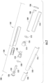
- FIG. 2 illustrates an exploded view of an aerosol delivery device 1200 according to an additional example embodiment of the present disclosure.
- the aerosol delivery device 1200 may include a control body 1202 and a cartridge 1204.
- the control body 1202 may include an end cap 1206, a circuit board with an indicator 1208 (e.g., a light emitting diode (LED)), a connector circuit 1209, an electrical power source 1210 (e.g., a battery, which may be rechargeable), a flow sensor 1212, a coupler 1214, and an outer body 1216 (which may include one or more inlet apertures 1233).
- the cartridge 1204 may include a base 1218, a combined dispenser and atomizer assembly 1220, a reservoir 1222, a lid 1224, a mouthpiece 1226, and an outer body 1228.
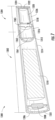
- FIG. 3 illustrates a modified sectional view through the aerosol delivery device 1200 of FIG. 2 .
- the base 1218 of the cartridge 1204 may be configured to engage the coupler 1214 of the control body 1202 to form a mechanical and electrical connection therebetween.
- the connection between the base 1218 of the cartridge 1204 and the coupler 1214 of the control body 1202 may be releasable such that, for example, the cartridge may be replaced when an aerosol precursor composition 1246 (see, FIG. 6 ) received therein is expended.
- FIG. 2 illustrates wiring 1230 as being coupled to the base 1218, the wiring may actually be coupled to the coupler 1214 so as to allow for releasable connection between the cartridge 1204 and the control body 1202 in some embodiments.
- FIG. 3 further illustrates a flow path of air through the aerosol delivery device 1200 when a user draws on the mouthpiece 1226.
- an airflow or flow of ambient air 1232 may enter the aerosol delivery device 1200 through the one or more inlet apertures 1233 and travel proximate or past the flow sensor 1212.
- the air 1232 may then travel through at least one coupler aperture 1261 in the coupler 1214 and at least one base aperture 1263 in the base 1218, around the combined dispenser and atomizer assembly 1220 and the reservoir 1222 (e.g., via one or more aerosol delivery apertures 1265 defined in the outer body 1228 or a space between the reservoir and the outer body), and out the mouthpiece 1226.
- the inlet apertures 1233 may be defined in the outer body 1216 of the control body 1202 such that the flow sensor 1212, which may also be positioned in the control body, may detect flow of the air 1232.
- the control body 1202 may be reusable, whereas the cartridge 1204 may be disposable. In this regard, whereas certain components within the cartridge 1204 may degrade or be depleted, the flow sensor 1212 and other components within the control body may maintain full functionality despite repeated use. Accordingly, positioning the flow sensor 1212 in the control body 1202 and providing a corresponding flow path of the air 1232 through the control body, or otherwise providing for fluid communication of the air traveling through the aerosol delivery device 1200 with the flow sensor, may decrease the cost of the cartridge 1204 by decreasing the number and type of components received therein.
- a pressure tap may be employed to allow a flow sensor in a control body to detect a flow of air through a cartridge substantially without any airflow through the control body as described, for example, in U.S. Pat. App. Ser. No. 14/193,961, filed February 28, 2014, to Worm et al. , which is incorporated herein by reference in its entirety.
- the lid 1224 and the combined dispenser and atomizer assembly 1220 may be coupled to opposing ends of the reservoir 1222. Accordingly, the lid 1224 and the combined dispenser and atomizer assembly 1220 may enclose the reservoir 1222 and retain the aerosol precursor composition 1246 (see, FIG. 6 ) therein. However, when the flow sensor 1212 detects the puff, the combined dispenser and atomizer assembly 1220 may be actuated such that the aerosol precursor composition 1246 (see, FIG. 6 ) is controllably dispensed from the reservoir 1222.
- FIG. 4 illustrates a partial sectional view through the combined dispenser and atomizer assembly.
- the combined dispenser and atomizer assembly 1220 may include a bubble jet head 1234 and an atomizer 1238 fixedly coupled thereto.
- the bubble jet head 1234 may be configured to dispense the aerosol precursor composition 1246 from the reservoir 1222 (see, e.g., FIG. 6 ).
- the atomizer 1238 may be configured to heat the aerosol precursor composition 1246 to produce an aerosol or vapor 1248 (see, FIG. 6 ).
- the bubble jet head 1234 may include one or more precursor inlets 1245, one or more precursor channels 1235, one or more first or ejection heating elements 1240, one or more precursor nozzles 1242, and a wafer, substrate, or housing 1241 respectively associated therewith.
- the housing 1241 may comprise silicon, ceramic, graphite, or other lower thermally-conductive and/or insulating materials.
- the precursor inlets 1245, the precursor channels 1235, and/or precursor nozzles 1242 may be defined by apertures in the housing 1241 in some embodiments.
- the precursor inlets, the precursor channels, and/or the precursor outlets may comprise separate elements coupled to the housing.
- the ejection heating elements 1240 may be positioned within one or more first or ejection chambers 1237, which may be defined by the housing 1241 of the bubble jet head 1234.
- the bubble jet head 1234 may comprise a standard inkjet printer head (e.g., a standard bubble jet print head sold by ImTech of Corvallis, Oregon or a 45 style jet head sold by Hewlett Packard of Palo Alto, California).
- the atomizer 1238 may be positioned relative to the bubble jet head 1234 so as to receive the aerosol precursor composition 1246 dispensed from the reservoir 1222 (see, FIG. 6 ).
- the atomizer 1238 is fixedly coupled to the bubble jet head 1234 such that the combined dispenser and atomizer assembly 1220 may be inserted into the outer body 1228 of the cartridge 1204 (see, e.g., FIG. 3 ) as a unit, rather than separately inserted into the outer body.
- the combined dispenser and atomizer assembly 1220 may be engaged with the reservoir 1222 and the combined assembly may be inserted into the outer body 1228 (see, e.g., FIG. 3 ).
- fixedly coupling the bubble jet head 1234 to the atomizer 1238 may allow for precise placement of these two components relative to one another such that the dispensed aerosol precursor composition 1246 (see, FIG. 6 ) is received at a proper location on the atomizer for atomization.
- the bubble jet head 1234 may be fixedly coupled to the atomizer 1238 via one or more spacers 1236.
- the atomizer 1238 may include a wafer, substrate, or housing 1243 that is coupled to the housing 1241 of the bubble jet head 1234 via the spacers 1236.
- the housing 1243 may comprise silicon, ceramic, graphite, or other nonconductive and/or insulating materials.
- the spacers 1236 may be configured to provide a gap between the bubble jet head 1234 and the atomizer 1238. In some embodiments the gap may be from about 1 mm to about 10 mm, and more preferably from about 1 mm to about 3 mm in order to reduce splattering of the aerosol precursor composition.
- the gap between the bubble jet head 1234 and the atomizer 1238 may be selected or adjusted to provide accurate delivery of the aerosol precursor composition to the heating surface of the atomizer based on a droplet dispersion pattern associated with ejection of the aerosol precursor composition from the bubble jet head (e.g., to prevent pooling of the aerosol precursor composition on one or more portions of the atomizer, to provide a thin, even film of the aerosol precursor composition across the heating surface of the atomizer, and/or to target a specific region of the atomizer).
- the atomizer 1238 may further include one or more second or vaporization heating elements 1244.
- a respective one of the vaporization heating elements 1244 may be associated with each ejection heating element 1240 and each nozzle 1242.
- the bubble jet head 1234 may be coupled to the reservoir 1222 or otherwise positioned in fluid communication therewith.
- the bubble jet head 1234 may be coupled to a distal end 1222A of the reservoir 1222 so as to block an opening 1222' to the reservoir and retain the aerosol precursor composition 1246 (see, FIG. 6 ) therein as described above.
- the precursor inlets 1245 in the bubble jet head 1234 may be in fluid communication with the reservoir 1222 and thereby the precursor channels 1235 may direct the aerosol precursor composition 1246 (see, FIG. 6 ) to the ejection chambers 1237 in which the ejection heating elements 1240 are positioned.
- Coupling the bubble jet head 1234 to the distal end 1222A of the reservoir 1222 may be advantageous in that it provides a relatively simple mechanism for attachment and fluid coupling.
- the reservoir 1222 may define a hollow, substantially cylindrical configuration, and the distal end 1222A may define a substantially planar configuration.
- the bubble jet head 1234 may be coupled (e.g., glued, adhered, or welded) to the distal end 1222A of the reservoir 1222 to enclose the reservoir and provide fluid communication between the reservoir and the bubble jet head.
- the bubble jet head 1234 may receive the aerosol precursor composition 1246 (see, FIG. 6 ) from the reservoir 1222.
- the reservoir 1222 may include a reservoir substrate 1239 configured to direct the aerosol precursor composition 1246 (see, FIG. 6 ) to the bubble jet head 1234.
- the reservoir substrate 1239 may comprise any material configured to wick or otherwise transport the aerosol precursor composition 1246 (see, FIG. 6 ) to the bubble jet head 1234, such as cellulose acetate, polyethylene terephthalate (PET), or any polymeric material, whether woven or nonwoven and whether fibrous or nonfibrous.
- the reservoir substrate 1239 may comprise one or more nonpolymeric materials that may be manufactured as an open cell foam or the like (e.g., ceramic foam, carbon foam, sintered glass), such that the material(s) define a porous media that provides wicking channels. Accordingly, by employing the reservoir substrate 1239, the aerosol precursor composition 1246 (see, FIG. 6 ) may be directed to the bubble jet head 1234 regardless of the orientation of the aerosol delivery device 1200 (see, e.g., FIG. 2 ), such that the aerosol delivery device does not have to be oriented in a particular manner during usage. In some embodiments the reservoir substrate may occupy only a portion of the longitudinal length of the reservoir.
- the reservoir substrate may only be positioned proximate the distal end of the reservoir to which the bubble jet head is attached.
- This configuration may provide substantially the same benefits noted above, because movement of the aerosol delivery device may cause the aerosol precursor composition to contact the reservoir substrate, while reducing the volume within the reservoir occupied by the reservoir substrate so as to allow for a greater fluid capacity therein.
- the aerosol precursor composition 1246 may initially be prevented from traveling through the remainder of the combined dispenser and atomizer assembly 1220 by the precursor nozzles 1242.
- the precursor nozzles 1242 may be appropriately sized to resist flow therethrough due to, for example, surface tension.
- a negative pressure in the reservoir e.g., as created by a spring and a piston within the reservoir or as a result of applying a negative pressure to the reservoir prior to sealing it shut, may resist passive leakage of the aerosol precursor composition out of the reservoir and through the bubble jet head.
- the bubble jet head 1234 may direct the aerosol precursor composition 1246 (see, FIG. 6 ) in the reservoir 1222 toward the atomizer 1238.
- current from the power source 1210 may be directed to the ejection heating elements 1240 to heat the aerosol precursor composition 1246 (see, FIG. 6 ) received through the precursor inlets 1245 and the precursor channels 1235 such that bubbles of vapor form, which eject droplets of the aerosol precursor composition through the precursor nozzles 1242 toward the atomizer 1238, as described and illustrated in greater detail below with respect to alternative embodiments of the present disclosure.
- Current from the power source 1210 may be applied to the vaporization heating elements 1244 prior to, simultaneously with, or after applying current to the ejection heating elements 1240.
- delaying application of the current to the vaporization heating elements 1244 until after the ejection heating elements 1240 receive current may assist in preventing wasted energy.
- some of the heat produced by the vaporization heating elements 1244 prior to the aerosol precursor composition 1246 (see, FIG. 6 ) coming in contact therewith may be undesirably transferred to surrounding portions of the aerosol delivery device 1200 or air within the aerosol delivery device, rather than applied to the aerosol precursor composition as desired.
- a plurality of walls defined by the housing 1241 of the bubble jet head 1234, the spacers 1236, and/or the housing 1243 of the atomizer 1238 may cooperatively define a second or vaporization chamber 1247 (see, e.g., FIG. 4 ) in which the vaporization heating elements 1244 are positioned and to which the aerosol precursor composition 1246 (see, FIG. 6 ) is delivered.
- a second or vaporization chamber 1247 see, e.g., FIG. 4
- the aerosol precursor composition 1246 see, FIG. 6
- the aerosol precursor composition 1246 may be directed into contact with the vaporization heating elements 1244 at the vaporization chamber 1247 to ensure vaporization thereof, prior to being directed into the flow of air 1232 through the aerosol delivery device 1200.
- the flow of air 1232 may extend generally around the combined dispenser and atomizer assembly 1220, rather than flow between the bubble jet head 1234 and the atomizer 1238 such that the flow of air does not direct the aerosol precursor composition away from the atomizer prior to atomization.
- the aerosol precursor composition may separate from the air and accumulate in the aerosol delivery device at a location outside of the reservoir. This could result in undesirable fluid leakage from the aerosol delivery device.
- the liquid aerosol precursor composition could reach the user's mouth, which may cause an undesirable taste or sensation.
- the droplets of the aerosol precursor composition 1246 ejected from the nozzles 1242 may be vaporized by the vaporization heating elements 1244 of the atomizer 1238 to produce an aerosol or vapor 1248 (see, FIG. 6 ).
- the vapor 1248 produced by the vaporization heating elements 1244 may then exit the combined dispenser and atomizer assembly 1220 and intermix and travel with the air 1232 to the mouthpiece 1226.
- the bubble jet head 1234 may be employed to precisely dispense the aerosol precursor composition 1246 (see, FIG.
- the electrical power directed to the bubble jet head 1234 and the atomizer 1238 from the power source 1210 may be controlled in one or more manners.
- the power directed to the bubble jet head 1234 may be independently controlled relative to the atomizer 1238 in one or more manners.
- pulse width and/or pulse amplitude modulation may be employed to provide an appropriate amount of current to the bubble jet head 1234 and the atomizer 1238. Relatively larger pulse widths and/or amplitudes may be employed to produce a relatively larger amount of heat.
- the ejection heating elements 1240 may have a relatively lower thermal mass and may be configured to heat the aerosol precursor composition 1246 to a relatively lesser degree than the vaporization heating elements 1244 in order to eject and dispense the aerosol precursor composition, rather than fully vaporize the aerosol precursor composition, which occurs at the atomizer 1238.
- ejection of the aerosol precursor composition may involve vaporization, only a small portion of the aerosol precursor composition is vaporized and the vaporization occurs in the substantially enclosed ejection chamber 1237 such that one or more droplets of the aerosol precursor composition are ejected therefrom.
- the vaporization heating elements may be configured to vaporize an entirety of the aerosol precursor composition directed thereto.
- relatively smaller pulse widths and/or amplitudes of power may be directed to the ejection heating elements as compared to the pulse widths and/or amplitudes of power directed to the vaporization heating elements.
- the application of power to the vaporization heating elements 1244 may be delayed in relation to application of power to the ejection heating elements 1240, such that energy is not wasted at the vaporization heating elements prior to ejection of the aerosol precursor composition.
- the bubble jet head may comprise a substantially conventional bubble jet head, such as an inkjet head employed in a printer.
- the inkjet head may be modified for use in the aerosol delivery devices of the present disclosure.
- the number of precursor nozzles and precursor inlets leading thereto may be adjusted, the diameter and/or shape of the precursor inlets and/or the precursor nozzles may be adjusted, the size of the ejection heating elements in the bubble jet head may be adjusted, the heat outputted by the ejection heating elements may be adjusted, the pulse width of power applied to the ejection heating elements in the bubble jet head may be adjusted, and/or various other characteristics may be adjusted.
- These changes may accommodate the differences in viscosity of the aerosol precursor composition versus ink as well as the goal of directing the aerosol precursor composition at an atomizer to vaporize the aerosol precursor composition, as opposed to printing ink on a substrate such as paper.
- the present disclosure provides various additional embodiments of aerosol delivery devices including bubble jet heads configured to dispense an aerosol precursor composition to an atomizer.
- bubble jet heads configured to dispense an aerosol precursor composition to an atomizer.
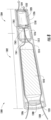
- FIG. 7 illustrates a sectional view through an aerosol delivery device 1300 according to an additional example embodiment of the present disclosure.
- the aerosol delivery device 1300 may include a control body 1302 and a cartridge 1304.
- the control body 1302 may include an end cap 1306, a flow sensor 1308, an electrical power source 1310 (e.g., a battery, which may be rechargeable), a coupler 1312 defining at least one coupler aperture 1361, and an outer body 1314.
- the control body may additionally include a circuit board with an indicator (e.g., a light emitting diode (LED)) and a connector circuit as described elsewhere herein.
- LED light emitting diode
- the cartridge 1304 may include a base 1316 defining at least one base aperture 1363, a combined dispenser and atomizer assembly 1318, a reservoir 1320, a lid 1322 that encloses the reservoir, a mouthpiece 1324, and an outer body 1326 defining one or more aerosol delivery apertures 1365.
- the base 1316 of the cartridge 1304 may be configured to engage the coupler 1312 of the control body 1302 to form a mechanical and electrical connection therebetween, which may be releasable to allow for replacement of the cartridge.
- FIG. 8 illustrates a sectional view through the aerosol delivery device 1300 showing a flow path of air through the aerosol delivery device when a user draws on the mouthpiece 1324.
- an airflow or flow of ambient air 1328 may enter the aerosol delivery device 1300 through one or more inlet apertures 1331 and travel past or proximate the flow sensor 1308 and around the electrical power source 1310.
- the ambient air 1328 is illustrated as flowing around the electrical power source 1310, in other embodiments the air may not flow past the electrical power source and/or the flow sensor may be positioned at an alternative location.
- the inlet apertures 1331 may be positioned at various alternate locations and defined in other components, such as in the outer body 1314 of the control body 1302 between the electrical power source 1310 and the coupler 1312.
- the air 1328 may flow from the control body 1302 through the aperture 1361 in the coupler 1312 and into and through the base aperture 1363 in the base 1316, around the combined dispenser and atomizer assembly 1318 and the reservoir 1320 (e.g., via the aerosol delivery apertures 1365 defined in the outer body 1326 or between the reservoir and the outer body), and out the mouthpiece 1324.
- the combined dispenser and atomizer assembly 1318 may be activated.
- the combined dispenser and atomizer assembly 1318 may receive an aerosol precursor composition 1330 from the reservoir 1320 and produce an aerosol or vapor 1332.
- the combined dispenser and atomizer assembly 1318 may include a wafer, substrate, or housing 1333 defining at least one precursor inlet 1334 through which the aerosol precursor composition 1330 is received.
- the aerosol precursor composition 1330 may then travel through one or more precursor channels 1335 to one or more precursor nozzles 1336.
- the precursor inlet 1334, the precursor channels 1335, and/or the precursor nozzles 1336 may be defined by the housing 1333.
- the precursor inlets, the precursor channels, and/or the precursor outlets may comprise separate components coupled to the housing.
- the aerosol precursor composition 1330 may initially be prevented from traveling through the remainder of the combined dispenser and atomizer assembly 1318 by the precursor nozzles 1336 leading thereto.
- the precursor nozzles 1336 may be appropriately sized to resist flow therethrough due to, for example, surface tension.
- the aerosol precursor composition may be exposed to a negative pressure within the reservoir as discussed above to reduce the likelihood of fluid leakage through the combined dispenser and atomizer assembly.
- the flow sensor 1308 detects the puff on the aerosol delivery device 1300
- current may be directed from the power source 1310 (see, e.g., FIG. 8 ) to one or more first or ejection heating elements 1338 positioned within a first or ejection chamber 1339 defined by the housing 1333.
- the ejection heating elements 1338 may heat the aerosol precursor composition 1330 such that the aerosol precursor composition 1330 boils and bubbles of vapor 1340 form.
- Each bubble of vapor 1340 expands extremely rapidly, creating a pressure pulse that then causes a droplet 1342 of the aerosol precursor composition 1330 to eject through a respective one of the precursor nozzles 1336.
- the bubble of vapor 1340 collapses as the aerosol precursor composition 1330 and the bubble of vapor 1340 cools.
- Surface tension and surface energy associated with the aerosol precursor composition 1330 at the precursor nozzle 1336 and capillary forces due to interaction of aerosol precursor composition with the microfluid channel defined by the precursor inlet 1334, the precursor channels 1335, and the precursor nozzles may cause more of the aerosol precursor composition to be directed from the reservoir toward the ejection heating element 1338, such that the aerosol precursor composition replenishes the ejection chamber 1337 and such that the ejection cycle may be repeated.
- the combined bubble jet head and dispenser 1318 may comprise a bubble jet head 1350 including the ejection heating elements 1338, the precursor inlets 1334, the precursor channels 1335, and the precursor nozzles 1336.
- the droplets 1342 of the aerosol precursor composition 1330 may be ejected through the precursor nozzles 1336 toward one or more second or vaporization heating elements 1344.
- each ejection heating element 1338, precursor nozzle 1336, and vaporization heating element 1344 of a respective portion of the combined dispenser and atomizer assembly 1318 may be axially aligned such that aerosol precursor composition 1330 is ejected onto the vaporization heating elements.
- the vaporization heating elements 1344 may be positioned in a second or vaporization chamber 1346 defined by the housing 1333 and to which droplets 1342 of the aerosol precursor composition 1330 are delivered.
- a respective one of the vaporization heating elements 1344 may be associated with each ejection heating element 1338 and each of the precursor nozzles 1336. Thereby, the droplets 1342 of the aerosol precursor composition 1330 ejected from the precursor nozzles 1336 may be vaporized by the vaporization heating elements 1344 to produce the vapor 1332 (see, e.g., FIG. 9 ).
- the ejection heating elements 1338 may have a relatively lower thermal mass and may be configured to heat the aerosol precursor composition 1330 to a relatively lesser degree as compared to the vaporization heating elements 1344.
- the vapor 1332 (see, e.g., FIG. 9 ) produced by the vaporization heating elements 1344 may then exit the combined dispenser and atomizer assembly 1318 through one or more aerosol outlets 1348, which may be defined by the housing 1333 at the second chamber 1346.
- the aerosol outlets may define a larger area than an area of the precursor nozzles.
- the vapor 1332 may intermix and travel with the air 1328 toward the mouthpiece 1324 (see, e.g., FIG. 8 ).
- the vapor 1332 and the air 1328 may travel through the aerosol delivery apertures 1365 defined in the outer body 1326 of the cartridge 1304.
- the aerosol precursor composition may be ejected into, and vaporized within, the vaporization chambers 1346. Thereby, issues with respect to the aerosol precursor composition being directed into the air 1328 (see, e.g., FIG. 8 ) without first being atomized may be avoided.
- the combined dispenser and atomizer assembly 1318 of FIGS. 7-11 may be an integral unit (e.g., provided as a silicon chip) including both the bubble jet head 1350 (e.g., comprising the ejection heating elements 1338, the precursor inlets 1334, the precursor channels 1335, and the precursor nozzles 1336) and an atomizer 1352 (e.g., comprising the aerosol outlets 1348 and the vaporization heating elements 1344) fixedly coupled to one another via the housing 1333, which is configured for receipt within the outer body 1326 of the cartridge 1304 (see, e.g., FIG. 8 ).
- 2-6 may include a standard bubble jet head 1234 (e.g., a bubble jet head from an inkjet printer) which may be fixedly coupled to an atomizer 1238 (e.g., via the spacers 1236) and modified to act as a dispenser for dispensing an aerosol precursor composition to the atomizer.
- a standard bubble jet head 1234 e.g., a bubble jet head from an inkjet printer
- an atomizer 1238 e.g., via the spacers 1236
- FIG. 12 illustrates a sectional view through an aerosol delivery device 1400 according to an additional example embodiment of the present disclosure.
- the aerosol delivery device 1400 may include a control body 1402 and a cartridge 1404, which are illustrated in a decoupled configuration.
- the control body 1402 may include an end cap 1406, a circuit board with an indicator 1408 (e.g., a light emitting diode (LED)), a connector circuit 1409, an electrical power source 1410 (e.g., a battery, which may be rechargeable), a flow sensor 1411 (e.g., a puff sensor or pressure switch), a coupler 1412, wiring 1413, and an outer body 1414.
- an indicator 1408 e.g., a light emitting diode (LED)
- a connector circuit 1409 e.g., an electrical power source 1410 (e.g., a battery, which may be rechargeable)
- a flow sensor 1411 e.g., a puff sensor or pressure switch
- the cartridge 1404 may include a base 1416, a combined dispenser and atomizer assembly 1418, a reservoir 1420, a lid 1422 that encloses the reservoir, a mouthpiece 1424, and an outer body 1426.
- the base 1416 of the cartridge 1404 may be configured to engage the coupler 1412 of the control body 1402 to form a mechanical and electrical connection therebetween, which may be releasable to allow for replacement of the cartridge.
- FIG. 13 illustrates an enlarged partial sectional view of the aerosol delivery device 1400 wherein the control body 1402 and the cartridge 1404 are coupled to one another.
- the combined dispenser and atomizer assembly 1418 may comprise a bubble jet head 1450 and an atomizer 1452.
- the bubble jet head 1450 and the atomizer 1452 may comprise any of the components and features of the bubble jet heads and atomizers described elsewhere herein.
- the bubble jet head 1450 and the atomizer may be coupled via a flexible circuit 1453.
- the flexible circuit 1453 may be electrically coupled to the base 1416 such that the dispenser and atomizer assembly 1418 is electrically connected to the cartridge 1402 through the base and the coupler 1412.
- the flexible circuit 1453 may additionally electrically couple the bubble jet head 1450 to the atomizer 1452 such that power may be directed to the bubble jet head and the atomizer in the manners described elsewhere herein.
- the flexible circuit may mechanically couple the bubble jet head 1450 to the atomizer 1452 such that the bubble jet head and the atomizer are fixedly coupled to one another.
- the flexible circuit 1453 may comprise a high temperature polyamide substrate or other flexible, nonconductive material with a circuit printed, etched, or otherwise formed thereon.
- the combined dispenser and atomizer assembly 1418 may be coupled to the reservoir 1420 and then this assembly may be inserted into the outer body 1426 of the cartridge 1404.
- the mechanical coupling between the bubble jet head 1450 and the atomizer 1452 via the flexible circuit 1453 may allow for insertion in this manner.
- the flexible circuit 1453 may be configured to flex such that, for example, the combined dispenser and atomizer assembly 1418 may be pressed against the base 1416 to define a desired gap or separation between the bubble jet head 1450 and the atomizer 1452.
- the flexible circuit 1453 may initially position the bubble jet head 1450 and the atomizer 1452 at a relatively large separation and the flexible circuit may flex during assembly for example, as a result of contact with the base 1416 to define the desired separation.
- the outer body 1414 of the control body 1402 may define one or more inlet apertures 1431
- the coupler 1412 may define at least one coupler aperture 1427
- the base 1416 may define at least one base aperture 1429
- the outer body 1426 of the cartridge 1404 may define at least one aerosol delivery aperture 1465, which may allow flow of air through the aerosol delivery device 1400.
- FIG. 14 illustrates a sectional view through the aerosol delivery device 1400 showing a flow path of air through the aerosol delivery device when a user draws on the mouthpiece 1424.
- an airflow or flow of ambient air 1428 may enter the aerosol delivery device 1400 through the inlet apertures 1431 which may be defined in the outer body 1414 of the control body 1402 and travel past or proximate the flow sensor 1411.
- the air 1428 may flow from the control body 1402 through the coupler 1412 at the coupler aperture 1427 (see, FIG. 13 ) and through the base aperture 1429 defined in the base 1416 of the cartridge 1404, through and/or around the combined dispenser and atomizer assembly 1418, around the reservoir 1420 (e.g., through the aerosol delivery aperture 1465 defined in the outer body 1426 or between the reservoir and the outer body, as illustrated in FIG. 15 ), and out the mouthpiece 1424.
- the aerosol delivery aperture 1465 is illustrated as defining a nonlinear flow path, in other embodiments the aerosol delivery aperture may define a linear flow path (e.g., extending parallel to the longitudinal length of the cartridge) in order to simplify manufacturing of the cartridge and provide a flow path with a smaller pressure drop.
- the air 1428 may travel through the base 1416 via the at least one base aperture 1429 (see, FIG. 13 ).
- the base aperture 1429 may be positioned proximate a radially outer edge of the base 1412.
- the air 1428 may enter the cartridge proximate an inner surface of the outer body 1426.
- the air 1428 may flow around and partially through the combined dispenser and atomizer assembly 1418 between the bubble jet head 1450 and the atomizer 1452 (see, FIG. 13 ).
- the combined dispenser and atomizer assembly 1418 may be activated such that the bubble jet head 1450 ejects the aerosol precursor composition from the reservoir 1420 toward the atomizer 1452 (see, FIG. 13 ).
- usage of the base aperture 1429 may regulate flow of the air through the combined dispenser and atomizer assembly such that substantially all of the aerosol precursor composition may come into contact with the atomizer 1452 (see, FIG.
- the air 1428 may flow around, rather than through, the combined dispenser and atomizer assembly 1418, such that the flow of the air may be distributed across a relatively large area and thereby the flow of the air through the combined dispenser and atomizer assembly may define a relatively low velocity which may not affect dispensing of the aerosol precursor composition onto the atomizer 1452 (see, FIG. 13 ) to a great extent.
- the flexible circuit 1453 and/or housings of the bubble jet head 1450 and the atomizer 1452 may define a vaporization chamber that further resists directing the aerosol precursor composition into the flow of air 1428 without being atomized.
- the atomizer may be shifted downstream of the bubble jet head to account for movement of the aerosol precursor composition caused by the flow of air. Following atomization, the air and vapor may travel around the reservoir 1422 and out the mouthpiece 1424 to the user.
- the embodiments of the aerosol delivery device including a flex circuit may be configured to avoid issues with respect to liquid aerosol precursor composition becoming entrained with air without being vaporized.
- the bubble jet head and the atomizer may be spaced relatively close to one another and the atomizer may be heated to such a temperature that the aerosol precursor composition may be atomized even if it does not contact the atomizer.
- the flexible circuit 1453 may be employed to establish a mechanical and electrical connection between a bubble jet head 1450 and an atomizer 1452 of a combined dispenser and atomizer assembly 1418.
- the flexible circuit 1453 may also be configured to electrically connect the combined dispenser and atomizer assembly 1418 and the power source 1410 in the cartridge through the coupler 1412 and the base 1416.
- various other embodiments of combined dispensers and atomizer assemblies may be electrically connected to one or more other components of an aerosol delivery device via a flexible circuit.
- FIG. 15 illustrates a partial sectional view of an embodiment of an aerosol delivery device 1400' that is substantially similar to the aerosol delivery device 1400 of FIGS. 12-14 .
- the aerosol delivery device 1400' of FIG. 15 may include a combined dispenser and atomizer assembly 1418' comprising a shared wafer, substrate, or housing 1433', in which both a bubble jet head and an atomizer are housed.
- the combined dispenser and atomizer assembly 1418' of FIG. 15 may be substantially similar to the combined dispenser and atomizer assembly 1318 of FIG. 9 .
- the flexible circuit 1453 may be employed to provide an electrical connection to the combined dispenser and atomizer assembly regardless of whether or not the bubble jet head and the atomizer are positioned within separate housings or a shared housing. Note also that usage of the combined dispenser and atomizer assembly 1418' including a bubble jet head and the atomizer within the shared housing 1433', through which air does not flow, may avoid any issues with respect to the liquid precursor composition being carried by the flow of air without atomization.
- FIG. 16 illustrates a sectional view through an aerosol delivery device 1500 according to an additional example embodiment of the present disclosure.
- the aerosol delivery device 1500 may include a control body 1502 and a cartridge 1504, which are illustrated in a decoupled configuration.
- a base 1516 of the cartridge 1504 may be configured to engage a coupler 1512 of the control body 1502 to form a mechanical and electrical connection therebetween, which may be releasable to allow for replacement of the cartridge.
- the control body 1502 may include an end cap 1506, a circuit board with an indicator 1508 (e.g., a light emitting diode (LED)), a connector circuit 1509, an electrical power source 1510 (e.g., a battery, which may be rechargeable), a flow sensor 1511 (e.g., a puff sensor or pressure switch), the coupler 1512, wiring 1513, and an outer body 1514.
- the cartridge 1504 may include the base 1516, a combined dispenser and atomizer assembly 1518, a reservoir 1520, a mouthpiece 1524, an insulator 1555, and an outer body 1526.
- the coupler 1516 defines a lid 1522 that encloses the reservoir 1520. In this regard, by sealing shut an end of the reservoir 1520 with the coupler 1516, assembly of the cartridge 1504 may be simplified. However, in other embodiments the lid may comprise a component that is separate from the coupler.
- FIG. 17 illustrates an enlarged partial sectional view of the aerosol delivery device 1500 wherein the control body 1502 and the cartridge 1504 are coupled to one another.
- the combined dispenser and atomizer assembly 1518 may comprise a bubble jet head 1550 and an atomizer 1552, which may be fixedly coupled to one another (e.g., by one or more spacers).
- the bubble jet head 1550 and the atomizer 1552 may comprise any of the components and features of the bubble jet heads and atomizers described elsewhere herein.
- FIG. 17 further illustrates a flow path of air through the aerosol delivery device 1500 when a user draws on the mouthpiece 1524.
- an airflow or flow of ambient air 1528 may enter the aerosol delivery device 1500 through one or more inlet apertures 1531 which may be defined in the outer body 1514 of the control body 1502 and travel past or proximate the flow sensor 1511.
- the air 1528 may flow from the control body 1502 through at least one coupler aperture 1561 defined in the coupler 1512 and through one or more base apertures 1529 defined in the base 1516 of the cartridge 1504, around the reservoir 1520 (e.g., through one or more air delivery channels 1565 defined in the outer body 1526 or between the reservoir and the outer body), around and partially through the combined dispenser and atomizer assembly 1518, and out the mouthpiece 1524.
- the combined dispenser and atomizer assembly 1518 may be activated such that the bubble jet head 1550 ejects the aerosol precursor composition from the reservoir 1520 toward the atomizer 1552.
- usage of the one or more base apertures 1529 may regulate flow of the air through the combined dispenser and atomizer assembly such that substantially all of the aerosol precursor composition may come into contact with the atomizer 1552 (see, FIG. 13 ) and become atomized, rather than become entrained with the air in liquid form and thereafter potentially separate therefrom.
- some of the air 1528 may flow around, rather than through, the combined dispenser and atomizer assembly 1518, such that the flow of the air may be distributed across a relatively large area and thereby the flow of the air through the combined dispenser and atomizer assembly may define a relatively low velocity which may not affect dispensing of the aerosol precursor composition onto the atomizer 1552 (see, FIG. 13 ) to a great extent.
- one or more spacers and/or housings of the bubble jet head 1550 and the atomizer 1552 may define a vaporization chamber that further resists directing the aerosol precursor composition into the flow of air 1528 without being atomized and/or the atomizer may be positioned downstream of the bubble jet head to account for movement of the aerosol precursor composition caused by the flow of air. Following atomization, the air and vapor may travel around the reservoir 1522 and out the mouthpiece 1524 to the user.
- the reservoir is positioned between the mouthpiece and the combined dispenser and atomizer assembly, which may comprise a bubble jet head and an atomizer.
- the combined dispenser and atomizer assembly 1518 of the aerosol delivery device 1500 of FIGS. 16 and 17 is positioned between the reservoir 1520 and the mouthpiece 1524.
- the aerosol delivery device 1500 may further comprise an insulator 1555, as illustrated in FIG. 16 .
- the insulator 1555 may comprise any embodiment of insulating materials such as plastic, fiberglass, or phenolic materials. Further, the insulator 1555 may be positioned proximate, or define, one or both of the outer body 1526 and the mouthpiece 1524 or a portion thereof.
- FIG. 18 illustrates a sectional view through an aerosol delivery device 1600 according to an additional example embodiment of the present disclosure.
- the aerosol delivery device 1600 may include a control body 1602 and a cartridge 1604, which are illustrated in a coupled configuration.
- a base 1616 of the cartridge 1604 may be configured to engage a coupler 1612 of the control body 1602 to form a mechanical and electrical connection therebetween, which may be releasable to allow for replacement of the cartridge.
- the control body 1602 may include an end cap 1606, a circuit board with an indicator 1608 (e.g., a light emitting diode (LED)), a connector circuit 1609, an electrical power source 1610 (e.g., a battery, which may be rechargeable), a flow sensor 1611 (e.g., a puff sensor or pressure switch), the coupler 1612, wiring 1613, and an outer body 1614.
- the cartridge 1604 may include the base 1616, a combined dispenser and atomizer assembly 1618, a reservoir 1620, a mouthpiece 1624, and an outer body 1626.
- the coupler 1616 defines a lid 1622 that encloses the reservoir 1620. In this regard, by sealing shut an end of the reservoir 1620 with the coupler 1616, assembly of the cartridge 1604 may be simplified.
- the lid may comprise a component that is separate from the coupler.
- FIG. 19 illustrates an enlarged partial sectional view of the aerosol delivery device 1600 wherein the control body 1602 and the cartridge 1604 are coupled to one another.
- the combined dispenser and atomizer assembly 1618 may comprise a bubble jet head 1650 and an atomizer 1652, which may be fixedly coupled to one another (e.g., by one or more spacers 1636).
- the bubble jet head 1650 and the atomizer 1652 may comprise any of the components and features of the bubble jet heads and atomizers described elsewhere herein.
- outer body 1614 of the control body 1602 may define one or more inlet apertures 1631
- the coupler 1612 may define at least one coupler aperture 1661
- the base 1616 may define at least one base aperture 1629, which may allow flow of air through the aerosol delivery device 1600.
- FIG. 19 further illustrates a flow path of air through the aerosol delivery device 1600 when a user draws on the mouthpiece 1624.
- an airflow or flow of ambient air 1628 may enter the aerosol delivery device 1600 through the inlet apertures 1631, which may be defined in the outer body 1614 of the control body 1602, and travel past or proximate the flow sensor 1611.
- the air 1628 may flow from the control body 1602 through the coupler aperture 1661 defined in the coupler 1612 and through the base 1616 of the cartridge 1604 via the base aperture 1629, between the reservoir 1620 and the outer body 1626, around and partially through the combined dispenser and atomizer assembly 1618, and out the mouthpiece 1624.
- the combined dispenser and atomizer assembly 1618 may be activated such that the bubble jet head 1650 ejects the aerosol precursor composition from the reservoir 1620 toward the atomizer 1652.
- usage of the at least one base aperture 1629 may regulate flow of the air through the combined dispenser and atomizer assembly such that substantially all of the aerosol precursor composition may come into contact with the atomizer 1652 and become atomized, rather than become entrained with the air in liquid form and thereafter potentially separate therefrom.
- some of the air 1628 may flow around, rather than through, the combined dispenser and atomizer assembly 1618, such that the flow of the air may be distributed across a relatively large area and thereby the flow of the air through the combined dispenser and atomizer assembly may define a relatively low velocity which may not affect dispensing of the aerosol precursor composition onto the atomizer 1652 to a great extent.
- the spacers 1636 and/or housings of the bubble jet head 1650 and the atomizer 1652 may define a vaporization chamber that further resists directing the aerosol precursor composition into the flow of air 1628 without being atomized, and/or the atomizer may be positioned downstream from the bubble jet head to account for movement of the aerosol precursor composition caused by the flow of air.. Following atomization, the air and vapor may travel around the reservoir 1620 and out the mouthpiece 1624 to the user.
- the combined dispenser and atomizer assembly may be positioned proximate the mouthpiece 1624, which may provide benefits in terms of avoiding condensation of the vaporized aerosol precursor condensation within the aerosol delivery device as described above.
- An insulator may be employed proximate the mouthpiece in order to reduce the amount of heat transferred to a user's lips as further described above.
- the combined dispenser and atomizer assembly 1618 may be coupled to a lateral side 1655 of the reservoir 1620. This configuration may allow for substantially longitudinal flow through the combined dispenser and atomizer assembly 1618 and to the mouthpiece 1624.
- a heating surface of the atomizer 1652 (e.g., comprising the outer surfaces of vaporization heating elements as described above) and an ejection surface of the bubble jet head 1650 (e.g., comprising the precursor nozzles) may be oriented substantially parallel to a longitudinal axis of the outer body 1626 of the cartridge 1604 and a longitudinal axis of the aerosol delivery device 1600 as a whole.
- flow of the air 1628 may occur between parallel surfaces defined by the bubble jet head 1650 and the atomizer 1652 such that the flow of air and aerosol may proceed in a substantially linear manner to the mouthpiece 1624.
- the embodiments of aerosol delivery devices 1200, 1300, 1400, 1500 described above include embodiments of a combined dispenser and atomizer assembly attached to a distal end of the reservoir in a manner whereby the heating surface of the atomizer and the ejection surface of the bubble jet head are oriented substantially perpendicular to the outer body of the cartridge and a longitudinal axis of the aerosol delivery device as a whole.
- attaching the combined dispenser and atomizer assembly to the distal end of the reservoir provides for simplified construction of the aerosol delivery device, this configuration may result in a non-linear air flow path through the aerosol delivery device. For example, as illustrated in FIG.
- the air may make one or more sharp turns entering and/or exiting the combined dispenser and atomizer assembly when the bubble jet head and the atomizer are oriented perpendicularly to a longitudinal axis of the aerosol delivery device.
- These sharp turns may undesirably increase the pressure drop associated with usage of the aerosol delivery device such that a draw thereon may require relatively greater effort.
- sharp turns in the air flow path at or downstream of the combined dispenser and atomizer assembly may be detrimental in that such transitions may cause the aerosol to condense back into liquid form as a result of impacting surrounding structures within the aerosol delivery device (e.g., the outer body of the cartridge).
- the aerosol delivery device 1600 illustrated in FIGS. 18 and 19 is configured to avoid the above-noted problems.
- usage of bubble jet heads and atomizers oriented such that respective ejection and heating surfaces thereof are substantially perpendicular to a longitudinal axis of the cartridge, as described in the embodiments of aerosol delivery devices of FIGS. 2-17 may be desirable in that such a configuration may define a relatively slower airflow therethrough, such that atomization of the aerosol precursor composition may be improved.
- FIGS. 18 and 19 are illustrated as being configured such that respective ejection and heating surfaces thereof are oriented substantially parallel to the longitudinal axis of the cartridge and the aerosol delivery device as a whole, certain embodiments of aerosol delivery devices including bubble jet heads and the atomizers in which respective ejection and heating surfaces are oriented at non-zero angles with respect to a longitudinal axis of the outer body may still provide many of the benefits described above with respect to the aerosol delivery device 1600 of FIGS. 18 and 19 . In this regard, FIG.
- FIG. 20 illustrates a partial, schematic view of an aerosol delivery device 1700 including a combined dispenser and atomizer assembly 1718 wherein respective ejection and heating surfaces of a bubble jet head 1750 and an atomizer 1752 thereof are oriented at a non-zero angle with respect to a longitudinal axis 1770 of the aerosol delivery device.
- the angle between these surfaces and the longitudinal axis 1770 are relatively small (e.g., less than about 45 degrees), such that a pressure drop caused by the turns in a flow path of air 1728 before exiting a mouthpiece 1724 is reduced as compared to embodiments of aerosol delivery devices that are otherwise similar but define sharper turns in the flow path.
- the relatively small angles between the ejection and heating surfaces of the bubble jet head 1750 and the atomizer 1752 and the longitudinal axis 1770 may also assist in avoiding issues with respect to condensation of the aerosol following vaporization and introduction into the flow of the air 1728, because the air and aerosol exiting the combined dispenser and atomizer assembly may smoothly exit therefrom without making a sharp turn.
- FIG. 21 illustrates a sectional view through an aerosol delivery device 1800 according to an additional example embodiment of the present disclosure.
- the aerosol delivery device 1800 may include a control body 1802 and a cartridge 1804, which are illustrated in a coupled configuration.
- a base 1816 of the cartridge 1804 may be configured to engage a coupler 1812 of the control body 1802 to form a mechanical and electrical connection therebetween, which may be releasable to allow for replacement of the cartridge.
- the control body 1802 may include an end cap 1806, a circuit board with an indicator 1808 (e.g., a light emitting diode (LED)), a connector circuit 1809, an electrical power source 1810 (e.g., a battery, which may be rechargeable), a flow sensor 1811 (e.g., a puff sensor or pressure switch), the coupler 1812, wiring 1813, and an outer body 1814.
- the cartridge 1804 may include the base 1816, a combined dispenser and atomizer assembly 1818, a reservoir 1820, a mouthpiece 1824, and an outer body 1826.
- the coupler 1816 defines a lid 1822 that encloses the reservoir 1820. In this regard, by sealing shut an end of the reservoir 1820 with the coupler 1816, assembly of the cartridge 1804 may be simplified.
- the lid may comprise a component that is separate from the coupler.
- FIG. 22 illustrates an enlarged partial sectional view of the aerosol delivery device 1800 wherein the control body 1802 and the cartridge 1804 are coupled to one another.
- the combined dispenser and atomizer assembly 1818 may comprise a bubble jet head 1850 and an atomizer 1852, which may be fixedly coupled to one another (e.g., by one or more spacers 1836).
- the bubble jet head 1850 and the atomizer 1852 may comprise any of the components and features of the bubble jet heads and atomizers described elsewhere herein.
- FIGS. 21 and 22 further illustrate a flow path of air through the aerosol delivery device 1800 when a user draws on the mouthpiece 1824.
- an airflow or flow of ambient air 1828 may enter the aerosol delivery device 1800 through one or more inlet apertures 1831 which may be defined in the outer body 1814 of the control body 1802 and travel past or proximate the flow sensor 1811.
- the air 1828 may flow from the control body 1802 through a coupler inlet 1861 defined in the coupler 1812 and into the base 1816 of the cartridge 1804, through the reservoir 1820, through the combined dispenser and atomizer assembly 1818, and out the mouthpiece 1824.
- the air 1828 may travel through the base 1816 via at least one base aperture 1829.
- the reservoir 1820 may define a channel 1854 extending therethrough.
- the reservoir 1820 may define an elongated annular configuration such that the aerosol precursor enclosed therein is separated from the channel 1854 (e.g., by an inner wall of the reservoir defining the channel).
- the channel 1854 may direct the flow of air 1828 to the combined dispenser and atomizer assembly 1818.
- the bubble jet head 1850 may include an air flow aperture 1856 and the atomizer 1852 may include an aerosol delivery aperture 1858 configured to direct the flow of air 1828 therethrough.
- the base aperture 1829, the channel 1854 through the reservoir 1820, the air flow aperture 1856 through the bubble jet head 1850, and the aerosol delivery aperture 1858 through the atomizer 1852 are linearly arranged along a longitudinal axis extending through the cartridge 1804 such that the flow of air 1828 travels along a substantially linear path and thereby issues with respect to increasing a pressure drop of the aerosol delivery device 1800 and causing condensation may be averted.
- the aerosol delivery device 1800 may be further configured to avoid the production of condensation as a result of the combined dispenser and atomizer assembly 1818 being positioned between the reservoir 1820 and the mouthpiece 1824.
- an insulator may be employed to reduce heat transfer to the mouthpiece and the outer body.
- FIG. 23 schematically illustrates an enlarged exploded view of the cartridge 1804 proximate the combined dispenser and atomizer assembly 1818.
- the reservoir 1820, the bubble jet head 1850, and the atomizer 1852 may be configured to dispense and atomize the aerosol precursor composition in a radial or an annular manner.
- the precursor inlets, precursor channels, ejection heating elements, and/or precursor nozzles of the bubble jet head 1850 may be positioned at a plurality of radial positions 1860 annularly about the air flow aperture 1856 extending through the bubble jet head.
- a vaporization heating element 1862 of the atomizer 1852 may extend substantially radially and annularly about the aerosol delivery aperture 1858 extending through the atomizer.
- This configuration may allow for dispensing and atomizing of the aerosol precursor composition around, rather than in, the direct flow of air 1828 through the aerosol delivery device 1800, so as to avoid directing liquid aerosol precursor composition into the flow of air.
- This configuration may also facilitate the substantially linear flow of air 1828, to combine the benefits of the aerosol delivery devices described above.
- the atomizer has generally been described as defining a substantially planar heating surface at which the vaporization heating element(s) are positioned.
- the bubble jet heads have defined an ejection surface on which the precursor nozzles are positioned that is also generally planar and parallel to the heating surface of the atomizer.
- the bubble jet head has ejected the aerosol precursor composition substantially perpendicularly to the heating surface of the atomizer.
- various other configurations of atomizers may be employed.
- FIG. 24 illustrates an atomizer 1900 according to an alternate embodiment of the present disclosure.
- the atomizer 1900 may be employed in conjunction with any of the combined dispenser and atomizer assemblies discussed elsewhere herein.
- the atomizer 1900 may be employed in place of the atomizer 1852 of the combined dispenser and atomizer assembly 1818 of the aerosol delivery device of FIGS. 21-23 .
- the atomizer 1900 may include an inner heating surface 1902 that is non-planar.
- the atomizer 1900 and the inner heating surface 1902 of the atomizer may be substantially conical (e.g., defining a hollow truncated conical configuration, as illustrated).
- the atomizer 1900 may be configured to receive a flow of air and aerosol precursor composition 1904 therethrough, such that the inner heating surface 1902 of the atomizer receives the flow of air and aerosol precursor composition 1904 thereon.
- the heating surface 1902 may atomize the aerosol precursor composition.
- a plurality of vaporization heating elements 1906 may be positioned on the inner heating surface 1902.
- the heating elements may be helically arranged on the inner heating surface 1902. This configuration may advantageously contact a majority of the aerosol precursor composition directed through the atomizer 1900. Thereby, a flow of air and aerosol 1908 may exit the atomizer 1900.
- FIG. 25 illustrates an alternate embodiment of an atomizer 2000, which may be employed in place of the atomizer 1852 of the combined dispenser and atomizer assembly 1818 of the aerosol delivery device of FIGS. 21-23 .
- the atomizer 2000 may include an outer heating surface 2002. As illustrated, the atomizer 2000 as a whole, in addition to the outer heating surface 2002, may define a substantially conical configuration. In this embodiment a flow of air and aerosol precursor composition 2004 may be directed toward a narrow end of the atomizer 2000. Thereby, the aerosol precursor composition may be vaporized by one or more vaporization heating elements 2006 positioned at the outer heating surface 2002 to produce a flow of air and aerosol 2008.
- the vaporization heating elements 2006 may be helically arranged on the outer heating surface 2002 in order to advantageously heat and vaporize the aerosol precursor composition.
- the vaporization heating element may comprise a single, continuous embedded or printed filament at the heating surface.
- the single continuous filament may define a helical configuration (e.g., at the inner heating surface in the atomizer illustrated in FIG. 24 or at the outer heating surface in the atomizer illustrated in FIG. 25 ), as described above. Usage of a single continuous filament for the vaporization heating element may be preferable in that it may simplify construction of the atomizer.
- a heating surface of an atomizer may define a non-planar configuration. Usage of an atomizer including a non-planar heating surface may allow for various alternate flow configurations through aerosol delivery devices.
- the substantially conical atomizers of FIGS. 24 and 25 may be respectively configured to focus or distribute air and aerosol while still providing for a substantially straight air flow path with a minimal increase in pressure drop associated with a puff on the aerosol delivery device.
- the bubble jet head may direct the aerosol precursor composition at a non-perpendicular angle relative to the heating surface of the atomizer.
- any splattered aerosol precursor composition may be retained within the atomizer and contact another portion of the inner heating surface 1902, such that the splattered aerosol precursor still becomes vaporized due to the inner heating surface of the atomizer defining a chamber.
- frustoconical atomizers are described in U.S. Pat. App. Ser. No. 14/329,334, filed July 11, 2014, to Taluskie et al .
- FIG. 26 illustrates an exploded view of an alternate embodiment of a combined dispenser and atomizer assembly 2100 which may be included in embodiments of the aerosol delivery devices disclosed herein.
- the combined dispenser and atomizer assembly 2100 may include a bubble jet head 2102 and an atomizer 2104. Details with respect to embodiments of bubble jet heads are described above and will not be repeated in their entirety.
- the bubble jet head 2102 may include a wafer, substrate, or housing 2106 which may define at least one precursor inlet 2108 (see, FIG. 27 ) configured to receive an aerosol precursor composition from a reservoir and at least one precursor nozzle 2110 configured to dispense the aerosol precursor composition to the atomizer 2104.
- the atomizer 2104 may comprise a wafer, substrate, or housing 2112. Additionally, as illustrated, in some embodiments the atomizer 2104 may further comprise a reinforcement member 2114.
- the reinforcement member 2114 may be configured to support the housing 2112 of the atomizer 2104 to provide structural stability thereto. For example, as illustrated in FIG. 27 , the reinforcement member 2114 may be coupled to the housing 2112 of the atomizer 2104 such that the housing is supported. In particular, the reinforcement member 2114 may be coupled to a back of the housing 2112, wherein at least one vaporization heating element 2116 is coupled to the front of the housing, opposite thereto.
- the reinforcement member may be configured to provide stiffness, support, and structure to the atomizer 2014 without substantially increasing the thermal mass thereof. It may be desirable to provide the atomizer 2104 with a relatively low thermal mass such that the atomizer may rapidly heat to a temperature sufficient to vaporize the aerosol precursor composition when current is applied thereto. Thus, the atomizer 2104 may rapidly heat when a user draws on the associated aerosol delivery device.
- the reinforcement member 2114 may avoid direct contact with the heating element to reduce heat transfer to the reinforcement member.
- the reinforcement member 2114 may define a cutout 2118.
- the cutout 2118 may further reduce the thermal mass of the atomizer 2104 while still allowing the reinforcement member 2114 to provide the atomizer with improved strength.
- the cutout may be centrally located such that the reinforcement member defines a frame extending around an outer edge of the housing 2112. This configuration results in only a relatively small loss in the moment of inertia of the reinforcement member 2114 while also positioning the mass thereof away from the vaporization heating element 2116 to further reduce heat transfer to the reinforcement member.
- the reinforcement member 2114 may comprise plastic, ceramic, glass, or other embodiments of insulating and non-conductive materials that are configured to avoid heat and electrical transfer thereto.
- the atomizer 2104 may further comprise one or more conductive pads 2120.
- the conductive pads 2120 may be configured to contact the vaporization heating element 2116 to direct current thereto.
- the conductive pads may comprise a material and/or configuration (e.g., thicker gauge) that defines a lower resistance than a material of the vaporization heating element 2116.
- the conductive pads 2120 may comprise silver palladium and the vaporization heating element 2116 may comprise platinum.
- the conductive pads 2120 may comprise silver palladium, and the vaporization heating element 2116 may comprise a silver palladium formulation defining a relatively greater resistance.
- various other materials may be employed in other embodiments including, for example, gold, silver, platinum, palladium, tungsten and combinations thereof.
- the materials defining the conductive pads and the vaporization heating element may be selected to define a desired resistance and appropriate bonding attributes with respect to the housing and/or other portions of the atomizer.
- the atomizer 2104 may be configured to fixedly engage the bubble jet head 2102 via posts 2103 (see, FIG. 27 ).
- the housing 2112 and/or the reinforcement member 2114 may define recesses 2122a, 2122b configured to engage the posts 2103.
- the posts 2103 may electrically couple the bubble jet head 2102 to the atomizer 2104.
- the conductive pads 2120 may be positioned proximate the recesses 2122a, 2122b defined in the atomizer 2104 such that an electrical connection may be established therebetween.
- FIGS. 28A-C illustrate enlarged partial views of embodiments of the atomizer 2104 of FIGS. 26 and 27 wherein the heating surface thereof is textured, rather than smooth. Note, however, that such texturing may be employed on any of the atomizers described herein.
- FIG. 28A illustrates an embodiment of the atomizer 2104A wherein a heating surface 2124A is crenellated.
- the heating surface 2124A defines a substantially regular pattern of protrusions and recesses.
- FIG. 28B illustrates an embodiment of the atomizer 2104B wherein a heating surface 2124B is partially porous.
- the topography of the heating surface 2124B may be substantially similar to that of a closed-cell foam.
- FIG. 28C illustrates an embodiment of the atomizer 2104C wherein a heating surface 2124C is fully porous.
- the topography of the heating surface 2102C may be substantially similar to that of an open-celled foam or a sintered material.
- the heating surface 2124A-C may be defined by, or coated with a passivation layer positioned at an outer surface thereof (e.g., on top of the housing 2112 and the vaporization heating element 2116.
- the passivation layer is configured to prevent oxidation, catalytic reactions, and various other chemical reactions from occurring at the atomizer when an aerosol precursor composition 2128 is sprayed thereon.
- the passivation layer may comprise aluminum oxide, glass, or a ceramic material, which may be sputtered or otherwise deposited over the vaporization heating elements 2116 and the housing 2112.
- the aerosol precursor composition may be less prone to splattering due to the textured heating surface capturing deflected aerosol precursor composition such that the aerosol precursor composition is less likely to deflect back to the bubble jet head. Further, usage of a textured heating surface may increase an effective area of the heating surface upon which the aerosol precursor composition is directed. Accordingly, heat may be more efficiently transferred to the aerosol precursor composition to improve vaporization of the aerosol precursor composition.
- the heating surface may include a wicking or absorptive layer, which may optionally define the textured surface, and which may be configured to reduce splatter and heat loss and perform other functions as described hereinafter.
- the absorptive layer which may comprise alumina paper in some embodiments, may be positioned outside of the passivation layer and may be configured to receive the aerosol precursor composition. Thereby, the aerosol precursor composition may saturate the absorptive layer, so that heat is applied to the aerosol precursor composition absorbed within this layer.
- the bubble jet head may replenish the aerosol precursor composition within the absorptive layer as it is vaporized.
- the absorptive layer may be at least partially saturated with the aerosol precursor composition in advance of receiving a draw on the aerosol delivery device, such that aerosol may be produced more rapidly.
- atomizers may include flat heaters, wound wire surfaces, micro heaters (e.g., embodied on a chip) glass plates, lasers, resistive heaters, and any other shape and embodiment of heater.
- a vaporization heating element may be respectively associated with each precursor nozzle and each ejection heating element of the bubble jet head.
- multiple precursor nozzles and multiple ejection heating elements may eject the aerosol precursor composition onto a single vaporization heating element to vaporize the aerosol precursor composition.
- the materials employed in the ejection heating elements and the vaporization heating elements may vary.
- the materials described above with respect to wire coil heating elements may be employed.
- Various other materials which may be employed in the ejection heating elements and the vaporization heating elements as well as the various other heating elements described herein may include platinum or a platinum-coated materials and resistive inks (e.g., printed on a ceramic material).
- the housing for one or both of the bubble jet head and the atomizer may comprise a silicon chip.
- one or both of the vaporization heating elements and the ejection heating elements may comprise the doped silicon of the silicon chip.
- part of the silicon chip may define a resistive circuit configured to produce heat to eject or vaporization the aerosol precursor composition.
- the aerosol precursor composition may be preheated.
- the ejection heating elements may be employed to preheat the aerosol precursor composition prior to heating the aerosol precursor composition to an extent such that a bubble of vapor forms and a droplet of the aerosol precursor composition is ejected through a precursor nozzle.
- Such preheating may involve applying a pulsed current to the ejection heating elements.
- a relatively smaller pulse width of power may be applied to the ejection heating elements of the bubble jet head during preheating the aerosol precursor composition as compared to a pulse width of the power applied to the ejection heating elements of the bubble jet head during dispensing of the aerosol precursor composition.
- the aerosol precursor composition may be diluted (e.g., with water) to decrease the viscosity thereof. Accordingly, use of the bubble jet head with an aerosol precursor composition may be facilitated in either or both of these manners.
- the viscosity of the aerosol precursor composition may initially define a range from about 5 to about 400 centipoise at 20 degrees Celsius.
- the viscosity of the aerosol precursor composition may be reduced through either or both of dilution (e.g., via water) or preheating to define a viscosity of less than about 100 centipoise at 20 degrees Celsius.
- ink employed in inkjet printers may generally define a relatively lower viscosity (e.g., from about 10 to about 40 centipoise at 20 degrees Celsius).
- the combined dispenser and atomizer assembly has generally been described as being positioned in a cartridge.
- the bubble jet head and/or the atomizer may be positioned in the control body.
- the bubble jet head may be positioned in the control body and configured to eject the aerosol precursor composition toward an atomizer in the cartridge.
- the aerosol precursor composition may be directed from a reservoir in the cartridge to the bubble jet head in the control body and back to the atomizer in the cartridge.
- the bubble jet head may be positioned in the cartridge and configured to eject the aerosol precursor composition from a reservoir in the cartridge toward an atomizer in the control body.
- FIG. 29 illustrates an alternate embodiment of an aerosol delivery device 2200 wherein a combined dispenser and atomizer assembly is positioned in the control body.
- the aerosol delivery device 2200 may include a control body 2202 and a cartridge 2204, which are illustrated in a decoupled configuration.
- a base 2216 of the cartridge 2204 may be configured to engage a coupler 2212 of the control body 2202 to form a mechanical and electrical connection therebetween, which may be releasable to allow for replacement of the cartridge.
- the control body 2202 may include an end cap 2206, a circuit board with an indicator 2208 (e.g., a light emitting diode (LED)), a connector circuit 2209, an electrical power source 2210 (e.g., a battery, which may be rechargeable), a flow sensor 2211 (e.g., a puff sensor or pressure switch), the coupler 2212, wiring 2213, a combined dispenser and atomizer assembly 2218, and an outer body 2214.
- the control body 2202 may further comprise a mounting plate 2219, and the combined dispenser and atomizer assembly 2218 may be mounted between the mounting plate and the coupler 2212.
- a bubble jet head 2250 of the combined dispenser and atomizer assembly 2218 may be coupled to the coupler 2212, an atomizer 2252 of the combined dispenser and atomizer assembly may be coupled to the mounting plate 2219, and the bubble jet head may be coupled to the atomizer via a flexible circuit 2253.
- the cartridge 2204 may include the base 2216, a reservoir 2220, a lid 2222 that encloses the reservoir, a mouthpiece 2224, and an outer body 2226.
- the reservoir 2220 may be in fluid communication with the bubble jet head 2250.
- the reservoir 2220 may define an outlet 2256.
- the base 2216 may also define an outlet 2258 that may align with the outlet 2256 to the reservoir 2220.
- One or both of the outlets 2256, 2258 may be initially sealed to retain an aerosol precursor composition in the reservoir 2220.
- a foil or plastic seal may cover the outlets 2256, 2258.
- the seal may be broken (e.g., by piercing the seal) when the base 2216 of the cartridge 2204 is engaged with the coupler 2212 of the control body 2202.
- the bubble jet head 2250 may receive the aerosol precursor composition transferred from the reservoir 2220 through the outlets 2256, 2258 and through an inlet 2260 at the coupler.
- the bubble jet head 2250 may dispense the aerosol precursor composition to the atomizer 2252 to produce an aerosol.
- a flow of air may enter through one or more inlet apertures 2262 in the outer body 2214 of the control body 2202 and travel through a mounting plate aperture 2261 defined in the mounting plate 2219 and through and/or around the combined dispenser and atomizer assembly 2218.
- the combined air and aerosol may thereby be directed through a coupler aperture 2267 defined in the coupler 2212, a base aperture 2263 defined in the base 2216, and through an aerosol delivery aperture 2265 defined in the outer body 2226 (or between the reservoir and the outer body) to the mouthpiece 2224.
- FIG. 30 illustrates an alternate embodiment of an aerosol delivery device 2300 wherein a combined dispenser and atomizer assembly is positioned in a separate dispenser and atomizer body.
- the aerosol delivery device 2200 may include a control body 2302, a dispenser and atomizer cartridge 2303, and a reservoir cartridge 2304, which are illustrated in a decoupled configuration.
- a base 2316 of the reservoir cartridge 2304 may be configured to engage a coupler 2364 of the dispenser and atomizer cartridge 2303, and a base 2366 of the dispenser and atomizer cartridge may be configured to engage a coupler 2312 of the control body 2302 to form mechanical and electrical connections therebetween, which may be releasable to allow for replacement of the dispenser and atomizer cartridge and/or the reservoir cartridge.
- the control body 2302 may include an end cap 2306, a circuit board with an indicator 2308 (e.g., a light emitting diode (LED)), a connector circuit 2309, an electrical power source 2310 (e.g., a battery, which may be rechargeable), a flow sensor 2311 (e.g., a puff sensor or pressure switch), the coupler 2312, and wiring 2313.
- the dispenser and atomizer cartridge 2303 may include an outer body 2371, the base 2366, the coupler 2364, and a combined dispenser and atomizer assembly 2318. As illustrated, in one embodiment the combined dispenser and atomizer assembly 2318 may be positioned between, and coupled to, the base 2366 and the coupler 2364.
- the combined dispenser and atomizer assembly 2318 may include a bubble jet head 2350 and an atomizer 2352, which may be connected via a flexible circuit 2353.
- the bubble jet head 2350 may be mounted to the coupler 2364 and the atomizer 2352 may be mounted to the base 2366 of the dispenser and atomizer cartridge 2303.
- the reservoir cartridge 2304 may include the base 2316, a reservoir 2320, a lid 2322 that encloses the reservoir, a mouthpiece 2324, and an outer body 2326.
- the reservoir 2320 may be in fluid communication with the bubble jet head 2350.
- the reservoir 2320 may define an outlet 2356.
- the base 2316 of the reservoir cartridge 2304 may also define an outlet 2358 that may align with the outlet 2356 to the reservoir.
- One or both of the outlets 2356, 2358 may be initially sealed to retain an aerosol precursor composition in the reservoir 2320.
- a foil or plastic seal may cover the outlets 2356, 2358.
- the seal may be broken (e.g., by piercing the seal) when the base 2316 of the reservoir cartridge 2304 is engaged with the coupler 2364 of the dispenser and atomizer cartridge 2303.
- the bubble jet head 2350 may receive the aerosol precursor composition transferred from the reservoir 2320 through the outlets 2356, 2358 and through an inlet 2360 at the coupler of the dispenser and atomizer assembly.
- the bubble jet head 2350 may dispense the aerosol precursor composition to the atomizer 2352 to produce an aerosol.
- a flow of air may enter through one or more inlet apertures 2362 in the outer body 2314 of the control body 2302 and thereby be directed through at least one coupler aperture 2361 defined in the coupler 2312 of the control body, at least one base aperture 2363 defined in the base 2366 and through and/or around the aerosol dispenser and atomizer assembly 2318.
- the combined air and aerosol may then travel through a coupler aperture 2365 defined in the coupler 2364 of the dispenser and atomizer cartridge 2303, through a base aperture 2367 defined in the base 2316 of the reservoir cartridge 2304, through a vapor delivery aperture 2369 defined in the outer body 2326 of the reservoir cartridge (or between the reservoir and the outer body) to the mouthpiece 2324.
- the combined dispenser and atomizer assembly may be positioned in the control body (see, e.g., FIG. 29 ). This configuration may be desirable in that the combined dispenser and atomizer assembly may have a usable life that exceeds that of the reservoir.
- the combined dispenser and atomizer assembly may be received in a separate dispenser and atomizer cartridge (see, e.g., FIG. 30 ).
- This configuration may be desirable in that although the combined dispenser and atomizer may have a usable life that exceeds that of the reservoir, the usable life of the combined dispenser and atomizer assembly may be less than that of the power source and other components of the control body, or vice versa. Further, this configuration may allow for substitution of alternate embodiments of combined dispensers and atomizer assemblies or control bodies to allow for customization of the aerosol delivery device to suit a user preferences (e.g., by employing a bubble jet head configured to produce a larger or smaller quantity of aerosol with each puff or by employing a control body with a larger battery).
- the bubble jet head has generally been described as being fixedly coupled to the atomizer that vaporizes the aerosol precursor composition.
- the bubble jet head is coupled to the atomizer via spacers.
- the bubble jet head is fixedly coupled to the atomizer via a shared housing.
- the bubble jet head is coupled to the atomizer via a flexible circuit and one or both of the atomizer and the bubble jet head is coupled to structure surrounding the combined dispenser and atomizer assembly (see, e.g., FIGS. 12-15 ).
- the bubble jet head may be decoupled from and aligned with the atomizer.
- the space between the bubble jet head and the atomizer may be adjusted for the particular design of the bubble jet head, the viscosity of the aerosol precursor composition, and various other factors.
- the atomizer and/or the bubble jet head may be configured to perform a cleaning cycle (e.g., by producing heat to remove aerosol precursor composition residue therefrom) either automatically (e.g., after a specified number of users) or manually when so directed by a user.
- a cleaning cycle e.g., by producing heat to remove aerosol precursor composition residue therefrom
- the bubble jet head and/or the atomizer is positioned in the control body or a dispenser and atomizer cartridge and hence configured for reuse with multiple reservoirs.
- the aerosol delivery devices described herein may avoid certain issues associated with conventional aerosol delivery devices that employ a wick to direct an aerosol precursor composition to an atomizer.
- use of a wick may cause separation of the ingredients of an aerosol precursor composition.
- use of a wick to transfer the aerosol precursor composition from a substrate to a heating element may result in leakage.
- the embodiments of the aerosol delivery devices disclosed herein may provide these and/or other advantages, including the advantages described above regarding greater control over the dispensed quantity of aerosol precursor composition.
- the bubble jet heads and the atomizers described herein may require less energy to dispense and atomize an aerosol precursor composition than other embodiments of fluid delivery and vaporization mechanisms.
- usage of a bubble jet head may allow for customization thereof (e.g., at the factory or by an end user). For example, the frequency and/or duration of dispensing by the bubble jet head may be adjusted to match a user's preferences.
- the aerosol delivery device may be configured to vaporize a relatively smaller or larger quantity of aerosol precursor composition with each puff on the aerosol delivery device, and such changes may be made without requiring a change in the hardware of the aerosol delivery device. In this regard, such changes may be implemented by software, or a change of electronic settings.
- aerosol delivery devices disclosed herein are generally described as including a cartridge (e.g., a replaceable cartridge) and a control body (e.g., a reusable control body), various other embodiments may be employed.
- the aerosol delivery devices may include more than two-pieces, (e.g., as described above with reference to FIG. 30 ).
- the aerosol delivery device may define an integral, one-piece configuration.
- any of the aerosol delivery devices disclosed herein may be configured in any of a variety of manners in one or more outer bodies.
- the atomizer may comprise a coil heater, which may receive an aerosol precursor composition dispense by a bubble jet head.
- a combined dispenser and atomizer assembly may include a housing with a first channel extending therethrough.
- the bubble jet head and the atomizer may be coupled to opposing sides of the first channel such that the bubble jet head may dispense an aerosol precursor composition onto the atomizer.
- a second channel defined in the housing may supply the aerosol precursor composition to the bubble jet head.
- the resultant vapor may exit the housing via the first channel in which the bubble jet head and the atomizer are received.
- a method for aerosolization in an aerosol delivery device may include directing an airflow from a control body comprising a power source through a cartridge comprising a reservoir at operation 2402. Further, the method may include dispensing an aerosol precursor composition from the reservoir via a bubble jet head at operation 2404. The method may additionally include heating the aerosol precursor composition dispensed from the reservoir by the bubble jet head with an atomizer at operation 2406.
- dispensing the aerosol precursor composition at operation 2404 and heating the aerosol precursor composition at operation 2406 comprise independently applying power from the power source to the bubble jet head and the atomizer. Further, dispensing the aerosol precursor composition at operation 2404 and heating the aerosol precursor composition at operation 2406 may comprise directing power to the atomizer after applying power to the bubble jet head. The method may further comprise preheating the aerosol precursor composition with the bubble jet head prior to dispensing the aerosol precursor composition at operation 2406. Additionally, the method may include detecting a temperature of the aerosol precursor composition, wherein preheating the aerosol precursor composition comprises preheating the aerosol precursor composition to a desired temperature. Preheating the aerosol precursor composition may comprise applying a relatively smaller pulse width of power to the bubble jet head as compared to dispensing the aerosol precursor composition.
Landscapes
- Health & Medical Sciences (AREA)
- Engineering & Computer Science (AREA)
- Veterinary Medicine (AREA)
- Biomedical Technology (AREA)
- Heart & Thoracic Surgery (AREA)
- Hematology (AREA)
- Life Sciences & Earth Sciences (AREA)
- Animal Behavior & Ethology (AREA)
- General Health & Medical Sciences (AREA)
- Anesthesiology (AREA)
- Public Health (AREA)
- Bioinformatics & Cheminformatics (AREA)
- Pulmonology (AREA)
- Mechanical Engineering (AREA)
- Chemical & Material Sciences (AREA)
- General Engineering & Computer Science (AREA)
- Combustion & Propulsion (AREA)
- Thermal Sciences (AREA)
- Physics & Mathematics (AREA)
- Chemical Kinetics & Catalysis (AREA)
- General Chemical & Material Sciences (AREA)
- Nozzles (AREA)
- Containers And Packaging Bodies Having A Special Means To Remove Contents (AREA)
- Medicinal Preparation (AREA)
- Catching Or Destruction (AREA)
Claims (15)
- Eine Aerosolabgabevorrichtung (1200, 1300, 1400, 1500, 1600, 1700, 1800, 2200), umfassend:ein Reservoir (1222, 1320, 1420, 1520, 1620, 1820, 2220, 2320), welches mindestens teilweise mit einer Aerosol-Precursor-Zusammensetzung (1246, 1330, 1904, 2004) gefüllt ist;einen Bubble-Jet-Kopf (1234, 1350, 1450, 1550, 1650, 1750, 1850, 2102, 2250, 2350) in Fluidverbindung mit dem Reservoir (1222, 1320, 1420, 1520, 1620, 1820, 2220, 2320), wobei der Bubble-Jet-Kopf (1234, 1350, 1450, 1550, 1650, 1750, 1850, 2102, 2250, 2350) dazu ausgebildet ist, die Aerosol-Precursor-Zusammensetzung (1246, 1330, 1904, 2004) aus dem Reservoir (1222, 1320, 1420, 1520, 1620, 1820, 2220, 2320) auszuteilen; undeinen Zerstäuber (1238, 1352, 1452, 1552, 1652, 1752, 1852, 1900, 2000, 2104, 2252, 2352), welcher dazu ausgebildet ist, die über den Bubble-Jet-Kopf (1234, 1350, 1450, 1550, 1650, 1750, 1850, 2102, 2250, 2350) ausgeteilte Aerosol-Precursor-Zusammensetzung (1246, 1330, 1904, 2004) zu erhitzen, um ein Aerosol zu erzeugen,dadurch gekennzeichnet, dass der Bubble-Jet-Kopf (1234, 1350, 1450, 1550, 1650, 1750, 1850, 2102, 2250, 2350) und der Zerstäuber (1238, 1352, 1452, 1552, 1652, 1752, 1852, 1900, 2000, 2104, 2252, 2352) fest miteinander verbunden sind, um eine kombinierte Einheit zu bilden derart, dass die Kombination von Zerstäuber (1238, 1352, 1452, 1552, 1652, 1752, 1852, 1900, 2000, 2104, 2252, 2352) und Bubble-Jet-Kopf (1234, 1350, 1450, 1550, 1650, 1750, 1850, 2102, 2250, 2350) als die kombinierte Einheit in eine Patrone (1204, 1304, 1404, 1504, 1604, 1804, 2204, 2304) der Aerosolabgabevorrichtung (1200, 1300, 1400, 1500, 1600, 1700, 1800, 2200) einführbar ist.
- Die Aerosolabgabevorrichtung (1200, 1300, 1400, 1500, 1600, 1700, 1800, 2200) nach Anspruch 1, wobei eine oder mehrere der folgenden Bedingungen erfüllt sind:der Bubble-Jet-Kopf (1234, 1350, 1450, 1550, 1650, 1750, 1850, 2102, 2250, 2350) ist dazu ausgebildet, die Aerosol-Precursor-Zusammensetzung (1246, 1330, 1904, 2004) im Wesentlichen senkrecht zu einer Heizfläche des Zerstäubers (1238, 1352, 1452, 1552, 1652, 1752, 1852, 1900, 2000, 2104, 2252, 2352) auszustoßen;eine Heizfläche des Zerstäubers (1238, 1352, 1452, 1552, 1652, 1752, 1852, 1900, 2000, 2104, 2252, 2352) ist nicht-planar, und wobei optional die Heizfläche des Zerstäubers (1238, 1352, 1452, 1552, 1652, 1752, 1852, 1900, 2000, 2104, 2252, 2352) im Wesentlichen konisch ist;eine Heizfläche des Zerstäubers (1238, 1352, 1452, 1552, 1652, 1752, 1852, 1900, 2000, 2104, 2252, 2352) ist strukturiert;das Reservoir (1222, 1320, 1420, 1520, 1620, 1820, 2220, 2320) umfasst ein Reservoirsubstrat (1239), welches dazu ausgebildet ist, die Aerosol-Precursor-Zusammensetzung (1246, 1330, 1904, 2004) zu dem Bubble-Jet-Kopf (1234, 1350, 1450, 1550, 1650, 1750, 1850, 2102, 2250, 2350) zu richten;der Bubble-Jet-Kopf (1234, 1350, 1450, 1550, 1650, 1750, 1850, 2102, 2250, 2350) ist mit einem distalen Ende (1222A) des Reservoirs (1222, 1320, 1420, 1520, 1620, 1820, 2220, 2320) gekoppelt;der Bubble-Jet-Kopf (1234, 1350, 1450, 1550, 1650, 1750, 1850, 2102, 2250, 2350) ist mit einer lateralen Seite (1655) des Reservoirs (1222, 1320, 1420, 1520, 1620, 1820, 2220, 2320) verbunden;der Bubble-Jet-Kopf (1234, 1350, 1450, 1550, 1650, 1750, 1850, 2102, 2250, 2350) und der Zerstäuber (1238, 1352, 1452, 1552, 1652, 1752, 1852, 1900, 2000, 2104, 2252, 2352) sind zwischen dem Reservoir (1222, 1320, 1420, 1520, 1620, 1820, 2220, 2320) und einem Mundstück (1226, 1324, 1424, 1524, 1624, 1724, 1824, 2224, 2324) positioniert;das Reservoir (1222, 1320, 1420, 1520, 1620, 1820, 2220, 2320) ist zwischen einem Mundstück (1226, 1324, 1424, 1524, 1624, 1724, 1824, 2224, 2324) und dem Zerstäuber (1238, 1352, 1452, 1552, 1652, 1752, 1852, 1900, 2000, 2104, 2252, 2352) und dem Bubble-Jet-Kopf (1234, 1350, 1450, 1550, 1650, 1750, 1850, 2102, 2250, 2350) positioniert;wobei die Patrone (1204, 1304, 1404, 1504, 1604, 1804, 2204, 2304) eine Basis (1218, 1316, 1416, 1516, 1616, 1816, 2216, 2316) und einen Kontrollkörper (1202, 1302, 1402, 1502, 1602, 1802, 2202, 2302) umfasst, welcher einen Koppler (1214, 1312, 1412, 1516, 1616, 1816, 2212, 2312) umfasst, wobei die Basis (1218, 1316, 1416, 1516, 1616, 1816, 2212, 2316) dazu ausgebildet ist, mit dem Koppler (1214, 1312, 1412, 1516, 1616, 1816, 2212, 2312) in Eingriff zu treten, um eine mechanische und elektrische Verbindung zwischen der Patrone (1204, 1304, 1404, 1504, 1604, 1804, 2204, 2304) und dem Kontrollkörper (1202, 1302, 1402, 1502, 1602, 1802, 2202, 2302) bereitzustellen.
- Die Aerosolabgabevorrichtung (1200, 1300, 1400, 1500, 1600, 1700, 1800, 2200) nach Anspruch 1 oder 2, ferner umfassend einen Außenkörper (1228, 1326, 1426, 1526, 1626, 1826, 2226, 2326) undein Gehäuse (1333, 1433'), welches innerhalb des Außenkörpers (1228, 1326, 1426, 1526, 1626, 1826, 2226, 2326) aufgenommen ist,wobei der Bubble-Jet-Kopf (1234, 1350, 1450, 1550, 1650, 1750, 1850, 2102, 2250, 2350) und der Zerstäuber (1238, 1352, 1452, 1552, 1652, 1752, 1852, 1900, 2000, 2104, 2252, 2352) über das Gehäuse (1333, 1433') fest miteinander gekoppelt sind.
- Die Aerosolabgabevorrichtung (1200, 1300, 1400, 1500, 1600, 1700, 1800, 2200) nach Anspruch 3, wobei der Bubble-Jet-Kopf (1234, 1350, 1450, 1550, 1650, 1750, 1850, 2102, 2250, 2350) ein Ausstoßheizelement (1240, 1338) umfasst und der Zerstäuber (1238, 1352, 1452, 1552, 1652, 1752, 1852, 1900, 2000, 2104, 2252, 2352) ein Verdampfungsheizelement (1244, 1344, 1862, 1906, 2006, 2116) umfasst.
- Die Aerosolabgabevorrichtung (1200, 1300, 1400, 1500, 1600, 1700, 1800, 2200) nach Anspruch 4, wobei eine thermische Masse des Ausstoßheizelements (1240, 1338) geringer ist als eine thermische Masse des Verdampfungsheizelements (1244, 1344, 1862, 1906, 2006, 2116).
- Die Aerosolabgabevorrichtung (1200, 1300, 1400, 1500, 1600, 1700, 1800, 2200) nach Anspruch 4, wobei der Bubble-Jet-Kopf (1234, 1350, 1450, 1550, 1650, 1750, 1850, 2102, 2250, 2350) ferner einen Precursor-Einlass (1245, 1334, 2108) und eine Precursor-Düse (1242, 1336, 2110) umfasst, undwobei der Zerstäuber (1238, 1352, 1452, 1552, 1652, 1752, 1852, 1900, 2000, 2104, 2252, 2352) ferner einen Aerosolauslass (1348) umfasst,wobei optional eine Fläche des Aerosolauslasses (1348) größer ist als eine Fläche der Precursor-Düse (1242, 1336, 2110),wobei optional das Ausstoßheizelement, die Precursor-Düse (1242, 1336, 2110) und das Verdampfungsheizelement (1244, 1344, 1862, 1906, 2006, 2116) axial ausgerichtet sind,wobei optional das Gehäuse (1333, 1433') mindestens eines von dem Precursor-Einlass (1245, 1334, 2108), der Precursor-Düse (1242, 1336, 2110) und dem Aerosolauslass (1348) definiert.
- Die Aerosolabgabevorrichtung (1200, 1300, 1400, 1500, 1600, 1700, 1800, 2200) nach Anspruch 1 oder Anspruch 2, wobei der Bubble-Jet-Kopf (1234, 1350, 1450, 1550, 1650, 1750, 1850, 2102, 2250, 2350) mit dem Zerstäuber (1238, 1352, 1452, 1552, 1652, 1752, 1852, 1900, 2000, 2104, 2252, 2352) über einen oder mehrere Abstandshalter (1236, 1636, 1836) gekoppelt ist, oder
wobei der Bubble-Jet-Kopf (1234, 1350, 1450, 1550, 1650, 1750, 1850, 2102, 2250, 2350) und der Zerstäuber (1238, 1352, 1452, 1552, 1652, 1752, 1852, 1900, 2000, 2104, 2252, 2352) über eine flexible Schaltungsanordnung (1453, 2253, 2353) elektrisch gekoppelt sind. - Die Aerosolabgabevorrichtung (1200, 1300, 1400, 1500, 1600, 1700, 1800, 2200) nach Anspruch 1 oder Anspruch 2, wobei der Zerstäuber (1238, 1352, 1452, 1552, 1652, 1752, 1852, 1900, 2000, 2104, 2252, 2352) umfasst: ein Gehäuse (2112), ein Verdampfungsheizelement (2116), welches mit dem Gehäuse (2112) gekoppelt ist, und ein Verstärkungsglied (2114), welches mit dem Gehäuse (2112) gekoppelt ist und dazu ausgebildet ist, dieses zu haltern.
- Die Aerosolabgabevorrichtung (1200, 1300, 1400, 1500, 1600, 1700, 1800, 2200) nach Anspruch 8, wobei das Verstärkungsglied (2114) einen Ausschnitt (2118) definiert.
- Die Aerosolabgabevorrichtung (1200, 1300, 1400, 1500, 1600, 1700, 1800, 2200) nach Anspruch 1 oder Anspruch 2, ferner umfassend einen Außenkörper, wobei eine Heizfläche des Zerstäubers (1238, 1352, 1452, 1552, 1652, 1752, 1852, 1900, 2000, 2104, 2252, 2352) in einem Nicht-Null-Winkel bezüglich einer Längsachse (1770) des Außenkörpers orientiert ist, oder
ferner umfassend einen Außenkörper, wobei eine Heizfläche des Zerstäubers (1238, 1352, 1452, 1552, 1652, 1752, 1852, 1900, 2000, 2104, 2252, 2352) im Wesentlichen parallel zu einer Längsachse des Außenkörpers (1626) orientiert ist. - Ein Verfahren zur Aerosolisierung in einer Aerosolabgabevorrichtung (1200, 1300, 1400, 1500, 1600, 1700, 1800, 2200), umfassend:Richten eines Luftstroms von einem Kontrollkörper (1202, 1302, 1402, 1502, 1602, 1802, 2202, 2302), welcher eine Leistungsquelle (1210, 1310, 1410, 1510, 1610, 1810, 2210, 2310) umfasst, durch eine Patrone (1204, 1304, 1404, 1504, 1604, 1804, 2204, 2304) hindurch, welche ein Reservoir (1222, 1320, 1420, 1520, 1620, 1820, 2220, 2320) umfasst;Austeilen einer Aerosol-Precursor-Zusammensetzung (1246, 1330, 1904, 2004) aus dem Reservoir (1222, 1320, 1420, 1520, 1620, 1820, 2220, 2320) über einen Bubble-Jet-Kopf (1234, 1350, 1450, 1550, 1650, 1750, 1850, 2102, 2250, 2350); undErhitzen der Aerosol-Precursor-Zusammensetzung (1246, 1330, 1904, 2004), welche aus dem Reservoir (1222, 1320, 1420, 1520, 1620, 1820, 2220, 2320) über den Bubble-Jet-Kopf (1234, 1350, 1450, 1550, 1650, 1750, 1850, 2102, 2250, 2350) ausgeteilt wird, mit einem Zerstäuber (1238, 1352, 1452, 1552, 1652, 1752, 1852, 1900, 2000, 2104, 2252, 2352),dadurch gekennzeichnet, dass der Bubble-Jet-Kopf (1234, 1350, 1450, 1550, 1650, 1750, 1850, 2102, 2250, 2350) und der Zerstäuber (1238, 1352, 1452, 1552, 1652, 1752, 1852, 1900, 2000, 2104, 2252, 2352) fest miteinander gekoppelt sind, um eine kombinierte Einheit zu bilden derart, dass die Kombination von Zerstäuber (1238, 1352, 1452, 1552, 1652, 1752, 1852, 1900, 2000, 2104, 2252, 2352) und Bubble-Jet-Kopf (1234, 1350, 1450, 1550, 1650, 1750, 1850, 2102, 2250, 2350) als die kombinierte Einheit in die Patrone (1204, 1304, 1404, 1504, 1604, 1804, 2204, 2304) der Aerosolabgabevorrichtung (1200, 1300, 1400, 1500, 1600, 1700, 1800, 2200) einführbar ist.
- Das Verfahren zur Aerosolisierung nach Anspruch 11, wobei das Austeilen der Aerosol-Precursor-Zusammensetzung (1246, 1330, 1904, 2004) und das Erhitzen der Aerosol-Precursor-Zusammensetzung (1246, 1330, 1904, 2004) umfasst: unabhängiges Anlegen von Leistung von der Leistungsquelle (1210, 1310, 1410, 1510, 1610, 1810, 2210, 2310) an den Bubble-Jet-Kopf (1234, 1350, 1450, 1550, 1650, 1750, 1850, 2102, 2250, 2350) und an den Zerstäuber (1238, 1352, 1452, 1552, 1652, 1752, 1852, 1900, 2000, 2104, 2252, 2352).
- Das Verfahren zur Aerosolisierung nach Anspruch 12, wobei das Austeilen der Aerosol-Precursor-Zusammensetzung (1246, 1330, 1904, 2004) und das Erhitzen der Aerosol-Precursor-Zusammensetzung (1246, 1330, 1904, 2004) umfasst: Richten von Leistung zu dem Zerstäuber (1238, 1352, 1452, 1552, 1652, 1752, 1852, 1900, 2000, 2104, 2252, 2352) nach Anlegen von Leistung an den Bubble-Jet-Kopf (1234, 1350, 1450, 1550, 1650, 1750, 1850, 2102, 2250, 2350).
- Das Verfahren zur Aerosolisierung nach Anspruch 12, ferner umfassend: Vorwärmen der Aerosol-Precursor-Zusammensetzung (1246, 1330, 1904, 2004) mit dem Bubble-Jet-Kopf (1234, 1350, 1450, 1550, 1650, 1750, 1850, 2102, 2250, 2350) vor Austeilen der Aerosol-Precursor-Zusammensetzung (1246, 1330, 1904, 2004).
- Das Verfahren zur Aerosolisierung nach Anspruch 14, wobei eine oder mehrere der folgenden Bedingungen erfüllt sind:das Verfahren zur Aerosolisierung umfasst ferner: Detektieren einer Temperatur der Aerosol-Precursor-Zusammensetzung (1246, 1330, 1904, 2004), wobei das Vorwärmen der Aerosol-Precursor-Zusammensetzung (1246, 1330, 1904, 2004) umfasst: Vorwärmen der Aerosol-Precursor-Zusammensetzung (1246, 1330, 1904, 2004) auf eine gewünschte Temperatur;das Vorwärmen der Aerosol-Precursor-Zusammensetzung (1246, 1330, 1904, 2004) umfasst ferner: Anlegen einer relativ kleineren Leistungspulsbreite oder Leistungspulsamplitude an den Bubble-Jet-Kopf (1234, 1350, 1450, 1550, 1650, 1750, 1850, 2102, 2250, 2350), verglichen mit dem Austeilen der Aerosol-Precursor-Zusammensetzung (1246, 1330, 1904, 2004).
Priority Applications (1)
| Application Number | Priority Date | Filing Date | Title |
|---|---|---|---|
| EP24182121.4A EP4406573A2 (de) | 2013-10-31 | 2014-10-29 | Aerosolabgabevorrichtung mit einem blasenstrahlkopf und zugehöriges verfahren |
Applications Claiming Priority (3)
| Application Number | Priority Date | Filing Date | Title |
|---|---|---|---|
| US201361897917P | 2013-10-31 | 2013-10-31 | |
| US14/524,778 US10548351B2 (en) | 2013-10-31 | 2014-10-27 | Aerosol delivery device including a bubble jet head and related method |
| PCT/US2014/062815 WO2015066127A1 (en) | 2013-10-31 | 2014-10-29 | Aerosol delivery device including a bubble jet head and related method |
Related Child Applications (1)
| Application Number | Title | Priority Date | Filing Date |
|---|---|---|---|
| EP24182121.4A Division EP4406573A2 (de) | 2013-10-31 | 2014-10-29 | Aerosolabgabevorrichtung mit einem blasenstrahlkopf und zugehöriges verfahren |
Publications (2)
| Publication Number | Publication Date |
|---|---|
| EP3062647A1 EP3062647A1 (de) | 2016-09-07 |
| EP3062647B1 true EP3062647B1 (de) | 2024-06-26 |
Family
ID=52994027
Family Applications (4)
| Application Number | Title | Priority Date | Filing Date |
|---|---|---|---|
| EP14799607.8A Active EP3062645B2 (de) | 2013-10-31 | 2014-10-29 | Aerosolabgabevorrichtung mit einem aerosolabgabemechanismus mit positiver verdrängung |
| EP14799610.2A Active EP3062646B1 (de) | 2013-10-31 | 2014-10-29 | Aerosolabgabevorrichtung mit einem druckbasierten aerosolabgabemechanismus |
| EP14802241.1A Active EP3062647B1 (de) | 2013-10-31 | 2014-10-29 | Aerosolabgabevorrichtung mit einem blasenstrahlkopf und entsprechendes verfahren |
| EP24182121.4A Pending EP4406573A2 (de) | 2013-10-31 | 2014-10-29 | Aerosolabgabevorrichtung mit einem blasenstrahlkopf und zugehöriges verfahren |
Family Applications Before (2)
| Application Number | Title | Priority Date | Filing Date |
|---|---|---|---|
| EP14799607.8A Active EP3062645B2 (de) | 2013-10-31 | 2014-10-29 | Aerosolabgabevorrichtung mit einem aerosolabgabemechanismus mit positiver verdrängung |
| EP14799610.2A Active EP3062646B1 (de) | 2013-10-31 | 2014-10-29 | Aerosolabgabevorrichtung mit einem druckbasierten aerosolabgabemechanismus |
Family Applications After (1)
| Application Number | Title | Priority Date | Filing Date |
|---|---|---|---|
| EP24182121.4A Pending EP4406573A2 (de) | 2013-10-31 | 2014-10-29 | Aerosolabgabevorrichtung mit einem blasenstrahlkopf und zugehöriges verfahren |
Country Status (10)
| Country | Link |
|---|---|
| US (6) | US10292424B2 (de) |
| EP (4) | EP3062645B2 (de) |
| JP (10) | JP6770430B2 (de) |
| KR (9) | KR20210135644A (de) |
| CN (6) | CN114431533A (de) |
| DE (1) | DE202014011551U1 (de) |
| ES (2) | ES2682326T5 (de) |
| PL (2) | PL3062646T3 (de) |
| RU (3) | RU2678892C2 (de) |
| WO (3) | WO2015066127A1 (de) |
Families Citing this family (236)
| Publication number | Priority date | Publication date | Assignee | Title |
|---|---|---|---|---|
| US10244793B2 (en) | 2005-07-19 | 2019-04-02 | Juul Labs, Inc. | Devices for vaporization of a substance |
| US20150328415A1 (en) * | 2014-05-19 | 2015-11-19 | R.J. Reynolds Tobacco Company | Cartridge vaporizer in a personal vaporizer unit |
| US10517530B2 (en) | 2012-08-28 | 2019-12-31 | Juul Labs, Inc. | Methods and devices for delivering and monitoring of tobacco, nicotine, or other substances |
| US10279934B2 (en) | 2013-03-15 | 2019-05-07 | Juul Labs, Inc. | Fillable vaporizer cartridge and method of filling |
| EP2993999B1 (de) | 2013-05-06 | 2021-01-27 | Juul Labs, Inc. | Nikotinsalzformulierungen für elektronische zigaretten und verfahren zur abgabe von nikotin |
| WO2014201432A1 (en) | 2013-06-14 | 2014-12-18 | Ploom, Inc. | Multiple heating elements with separate vaporizable materials in an electric vaporization device |
| USD741001S1 (en) * | 2013-07-16 | 2015-10-13 | Fontem Holdings 4 B.V. | Nozzle |
| US10292424B2 (en) * | 2013-10-31 | 2019-05-21 | Rai Strategic Holdings, Inc. | Aerosol delivery device including a pressure-based aerosol delivery mechanism |
| US10039321B2 (en) | 2013-11-12 | 2018-08-07 | Vmr Products Llc | Vaporizer |
| CN105979805B (zh) | 2013-12-05 | 2021-04-16 | 尤尔实验室有限公司 | 用于气雾剂装置的尼古丁液体制剂及其方法 |
| US10058129B2 (en) | 2013-12-23 | 2018-08-28 | Juul Labs, Inc. | Vaporization device systems and methods |
| HRP20211514T1 (hr) | 2013-12-23 | 2021-12-24 | Juul Labs International Inc. | Sustavi uređaja za isparavanje |
| USD842536S1 (en) | 2016-07-28 | 2019-03-05 | Juul Labs, Inc. | Vaporizer cartridge |
| USD825102S1 (en) | 2016-07-28 | 2018-08-07 | Juul Labs, Inc. | Vaporizer device with cartridge |
| US10159282B2 (en) | 2013-12-23 | 2018-12-25 | Juul Labs, Inc. | Cartridge for use with a vaporizer device |
| US10076139B2 (en) | 2013-12-23 | 2018-09-18 | Juul Labs, Inc. | Vaporizer apparatus |
| US20160366947A1 (en) | 2013-12-23 | 2016-12-22 | James Monsees | Vaporizer apparatus |
| PL3096636T3 (pl) * | 2014-01-22 | 2020-11-16 | Fontem Holdings 1 B.V. | Sposoby i urządzenia do łagodzenia potrzeby palenia |
| US10687552B2 (en) | 2014-02-10 | 2020-06-23 | Philip Morris Products S.A. | Cartridge with a heater assembly for an aerosol-generating system |
| KR20220066423A (ko) | 2014-02-10 | 2022-05-24 | 필립모리스 프로덕츠 에스.에이. | 에어로졸 발생 시스템용 카트리지 |
| EP3105992A1 (de) | 2014-02-10 | 2016-12-21 | Philip Morris Products S.A. | Flüssigkeitsdurchlässige heizeranordnung für ein aerosolerzeugungssystem und verfahren zur anordnung einer flüssigkeitsdurchlässigen heizervorrichtung für ein aerosolerzeugungssystem |
| US9833019B2 (en) * | 2014-02-13 | 2017-12-05 | Rai Strategic Holdings, Inc. | Method for assembling a cartridge for a smoking article |
| US10588176B2 (en) | 2014-02-28 | 2020-03-10 | Ayr Ltd. | Electronic vaporiser system |
| US10285430B2 (en) | 2014-02-28 | 2019-05-14 | Ayr Ltd. | Electronic vaporiser system |
| US11085550B2 (en) | 2014-02-28 | 2021-08-10 | Ayr Ltd. | Electronic vaporiser system |
| US10091839B2 (en) | 2014-02-28 | 2018-10-02 | Beyond Twenty Ltd. | Electronic vaporiser system |
| US10136674B2 (en) | 2014-02-28 | 2018-11-27 | Beyond Twenty Ltd. | Electronic vaporiser system |
| US10287154B2 (en) | 2014-02-28 | 2019-05-14 | Ayr Ltd. | Electronic vaporiser system |
| GB201413019D0 (en) | 2014-02-28 | 2014-09-03 | Beyond Twenty Ltd | Beyond 1B |
| CA2948851A1 (en) | 2014-05-16 | 2015-11-19 | Pax Labs, Inc. | Systems and methods for aerosolizing a smokeable material |
| ES2958716T3 (es) * | 2014-06-27 | 2024-02-13 | Fontem Ventures Bv | Dispositivo electrónico para fumar y sistema de cápsula |
| US10058123B2 (en) | 2014-07-11 | 2018-08-28 | R. J. Reynolds Tobacco Company | Heater for an aerosol delivery device and methods of formation thereof |
| US10765144B2 (en) | 2014-08-21 | 2020-09-08 | Rai Strategic Holdings, Inc. | Aerosol delivery device including a moveable cartridge and related assembly method |
| US9913493B2 (en) | 2014-08-21 | 2018-03-13 | Rai Strategic Holdings, Inc. | Aerosol delivery device including a moveable cartridge and related assembly method |
| US9451792B1 (en) * | 2014-09-05 | 2016-09-27 | Atmos Nation, LLC | Systems and methods for vaporizing assembly |
| JP6802792B2 (ja) | 2014-12-05 | 2020-12-23 | ジュール・ラブズ・インコーポレイテッドJuul Labs, Inc. | 調整された投与量の制御 |
| TWI674071B (zh) | 2014-12-15 | 2019-10-11 | 瑞士商菲利浦莫里斯製品股份有限公司 | 氣溶膠產生系統及用於在電熱式氣溶膠產生系統內導引氣流的方法 |
| AR103016A1 (es) | 2014-12-15 | 2017-04-12 | Philip Morris Products Sa | Sistemas generadores de aerosol y métodos para dirigir un flujo de aire hacia dentro de un sistema generador de aerosol calentado eléctricamente |
| US10178879B2 (en) * | 2015-01-29 | 2019-01-15 | Lawrence F Glaser | e-Cigarettes, e-Cigars, Vape-device public safety and protection mechanisms |
| US10117462B2 (en) * | 2015-02-02 | 2018-11-06 | Intrepid Brands, LLC | Personal electronic vaporizer |
| WO2016127004A1 (en) * | 2015-02-04 | 2016-08-11 | Lubby Holdings, LLC | Personal vaporizer with medium and chamber control |
| EP3153036B1 (de) * | 2015-02-05 | 2019-11-13 | O-Net Automation Technology (Shenzhen) Limited | Zerstäuber für e-zigarette |
| GB2535982A (en) * | 2015-02-13 | 2016-09-07 | Nerudia Ltd | System and apparatus |
| US10010111B2 (en) * | 2015-03-04 | 2018-07-03 | Altria Client Services Llc | E-vaping device |
| EP3075271B2 (de) | 2015-04-02 | 2022-09-14 | Fontem Holdings 1 B.V. | Elektronische rauchvorrichtung mit flüssigkeitsbehälter mit einem aktuator |
| US11882878B2 (en) | 2015-04-23 | 2024-01-30 | Altria Client Services Llc | Heating element and heater assemblies, cartridges, and e-vapor devices including a heating element |
| CN107635418B (zh) * | 2015-04-23 | 2020-12-29 | 奥驰亚客户服务有限责任公司 | 用于电子烟器具的电源部以及包括电源部的电子烟器具 |
| EA035155B1 (ru) | 2015-04-23 | 2020-05-06 | Олтриа Клайент Сервисиз Ллк | Единый нагревательный элемент и нагреватель, картридж и электронное испарительное устройство с единым нагревательным элементом |
| CN113749311B (zh) | 2015-04-30 | 2024-07-16 | 菲利普莫里斯生产公司 | 用于气溶胶生成系统的筒 |
| EP3632490A1 (de) | 2015-05-06 | 2020-04-08 | Altria Client Services LLC | Verbrennungsfreie rauchvorrichtung und komponenten davon |
| GB201508405D0 (en) | 2015-05-15 | 2015-07-01 | British American Tobacco Co | Article and apparatus for generating an aerosol |
| EP4173505B1 (de) * | 2015-06-04 | 2024-02-21 | Fontem Ventures B.V. | Entfernbarer zerstäuber und elektronische rauchvorrichtung mit seitlicher öffnung |
| RU2700159C2 (ru) * | 2015-06-12 | 2019-09-12 | Филип Моррис Продактс С.А. | Выдачной механизм |
| GB201511359D0 (en) | 2015-06-29 | 2015-08-12 | Nicoventures Holdings Ltd | Electronic vapour provision system |
| GB201511361D0 (en) | 2015-06-29 | 2015-08-12 | Nicoventures Holdings Ltd | Electronic vapour provision system |
| GB201511349D0 (en) | 2015-06-29 | 2015-08-12 | Nicoventures Holdings Ltd | Electronic aerosol provision systems |
| ES2951138T3 (es) | 2015-07-09 | 2023-10-18 | Philip Morris Products Sa | Unidad de calentamiento para un sistema generador de aerosol |
| US11504489B2 (en) * | 2015-07-17 | 2022-11-22 | Rai Strategic Holdings, Inc. | Contained liquid system for refilling aerosol delivery devices |
| PL3127441T3 (pl) * | 2015-08-06 | 2019-06-28 | Fontem Holdings 1 B.V. | Elektroniczne urządzenie do palenia ze szklaną rurką kapilarną |
| EP3331387B1 (de) * | 2015-08-07 | 2020-02-19 | Philip Morris Products S.a.s. | Aerosolerzeugungssystem mit verbessertem luftstrommanagement |
| CN107809921B (zh) * | 2015-08-07 | 2021-06-25 | 菲利普莫里斯生产公司 | 具有增强气流管理的气溶胶生成系统 |
| CN105077599B (zh) * | 2015-08-11 | 2017-10-17 | 深圳市新宜康科技有限公司 | 电子烟加压供液装置 |
| US10492528B2 (en) * | 2015-08-11 | 2019-12-03 | Altria Client Services Llc | Power supply section configuration for an electronic vaping device and electronic vaping device |
| PL3344315T3 (pl) | 2015-09-01 | 2023-10-02 | Ayr Ltd | Układ elektronicznego waporyzatora |
| US10034494B2 (en) | 2015-09-15 | 2018-07-31 | Rai Strategic Holdings, Inc. | Reservoir for aerosol delivery devices |
| WO2017053994A1 (en) * | 2015-09-25 | 2017-03-30 | Lubby Holdings Llc | Personal vaporizer having reversing air flow |
| US9669364B2 (en) * | 2015-10-02 | 2017-06-06 | Acoustic Arc International Limited | Bubble atomizer and method for atomizing liquid |
| US10058125B2 (en) * | 2015-10-13 | 2018-08-28 | Rai Strategic Holdings, Inc. | Method for assembling an aerosol delivery device |
| US11006667B2 (en) * | 2015-10-16 | 2021-05-18 | 14Th Round Inc. | Assembly for providing chemicals for smokeless administration, a disposable tank, and a method of using the same |
| US10021910B2 (en) | 2015-11-13 | 2018-07-17 | Altria Client Services Llc | E-vaping section and e-vaping device, and a method of manufacturing thereof |
| US9850891B2 (en) | 2015-11-25 | 2017-12-26 | Funai Electric Co., Ltd. | Analog flow control |
| US10440992B2 (en) * | 2015-12-07 | 2019-10-15 | Rai Strategic Holdings, Inc. | Motion sensing for an aerosol delivery device |
| WO2017108987A1 (en) * | 2015-12-22 | 2017-06-29 | Philip Morris Products S.A. | A cartridge for an aerosol-generating system and an aerosol-generating system comprising a cartridge |
| WO2017108394A1 (en) * | 2015-12-22 | 2017-06-29 | Philip Morris Products S.A. | Aerosol-generating system with motor |
| KR102664544B1 (ko) * | 2015-12-22 | 2024-05-10 | 필립모리스 프로덕츠 에스.에이. | 펌프를 갖는 에어로졸 발생 시스템 |
| US10398174B2 (en) | 2015-12-22 | 2019-09-03 | Altria Client Services Llc | Aerosol-generating system with pump |
| US10624392B2 (en) | 2015-12-22 | 2020-04-21 | Altria Client Services Llc | Aerosol-generating system with motor |
| US10092036B2 (en) | 2015-12-28 | 2018-10-09 | Rai Strategic Holdings, Inc. | Aerosol delivery device including a housing and a coupler |
| CN105533811B (zh) * | 2015-12-29 | 2018-06-22 | 广东亚一半导体应用科技有限公司 | 一种电子烟和电子烟的供液容器 |
| CN105581376B (zh) * | 2015-12-29 | 2018-06-22 | 广东亚一半导体应用科技有限公司 | 一种电子烟及用于电子烟的供液装置 |
| KR20180099685A (ko) * | 2015-12-31 | 2018-09-05 | 필립모리스 프로덕츠 에스.에이. | 다중 부분 전기 가열식 에어로졸 발생 시스템 |
| US10104912B2 (en) | 2016-01-20 | 2018-10-23 | Rai Strategic Holdings, Inc. | Control for an induction-based aerosol delivery device |
| US9961940B2 (en) * | 2016-01-22 | 2018-05-08 | Funai Electric Co., Ltd. | Vaporizing assembly and vapor generating device |
| US10015989B2 (en) * | 2016-01-27 | 2018-07-10 | Rai Strategic Holdings, Inc. | One-way valve for refilling an aerosol delivery device |
| WO2017139595A1 (en) | 2016-02-11 | 2017-08-17 | Pax Labs, Inc. | Fillable vaporizer cartridge and method of filling |
| US20190104767A1 (en) | 2016-02-11 | 2019-04-11 | Juul Labs, Inc. | Vaporizer devices with blow discrimination |
| SG10202108578XA (en) | 2016-02-11 | 2021-09-29 | Juul Labs Inc | Securely attaching cartridges for vaporizer devices |
| US11412781B2 (en) * | 2016-02-12 | 2022-08-16 | Rai Strategic Holdings, Inc. | Adapters for refilling an aerosol delivery device |
| BR112018067606A2 (pt) | 2016-02-25 | 2019-01-08 | Juul Labs Inc | métodos e sistemas de controle de dispositivo de vaporização |
| US10368580B2 (en) | 2016-03-08 | 2019-08-06 | Altria Client Services Llc | Combined cartridge for electronic vaping device |
| DE102016002665A1 (de) * | 2016-03-08 | 2017-09-14 | Hauni Maschinenbau Gmbh | Elektronisches Zigarettenprodukt und Kartusche für ein elektronisches Zigarettenprodukt |
| US10405582B2 (en) | 2016-03-10 | 2019-09-10 | Pax Labs, Inc. | Vaporization device with lip sensing |
| US20170258140A1 (en) * | 2016-03-11 | 2017-09-14 | Altria Client Services Llc | Multiple dispersion generator e-vaping device |
| RU2722095C2 (ru) * | 2016-03-31 | 2020-05-26 | Филип Моррис Продактс С.А. | Система, генерирующая аэрозоль, с отдельными капсулой и испарительным блоком |
| JP6946326B2 (ja) * | 2016-03-31 | 2021-10-06 | フィリップ・モーリス・プロダクツ・ソシエテ・アノニム | エアロゾル発生システムで使用する霧化組立品 |
| MX2018011471A (es) * | 2016-03-31 | 2019-01-10 | Philip Morris Products Sa | Unidad de vaporizacion que comprende elemento de calentamiento de tipo lamina y dispositivo de suministro de liquido para un sistema generador de aerosol. |
| US10617152B2 (en) | 2016-03-31 | 2020-04-14 | Altria Client Services Llc | Aerosol-generating system with separate capsule and vaporizer |
| US10440996B2 (en) * | 2016-03-31 | 2019-10-15 | Altria Client Services Llc | Atomizing assembly for use in an aerosol-generating system |
| US10104914B2 (en) * | 2016-03-31 | 2018-10-23 | Altria Client Services Llc | Airflow in aerosol generating system with mouthpiece |
| SG10202005440TA (en) * | 2016-04-22 | 2020-07-29 | Jt Int Sa | Aerosol generating device with a laser |
| GB201607475D0 (en) * | 2016-04-29 | 2016-06-15 | British American Tobacco Co | Article for generating an inhalable medium and method of heating a smokable material |
| US10405579B2 (en) * | 2016-04-29 | 2019-09-10 | Rai Strategic Holdings, Inc. | Methods for assembling a cartridge for an aerosol delivery device, and associated systems and apparatuses |
| GB201607474D0 (en) | 2016-04-29 | 2016-06-15 | British American Tobacco Co | Article, apparatus and method of heating a smokable material |
| USD849996S1 (en) | 2016-06-16 | 2019-05-28 | Pax Labs, Inc. | Vaporizer cartridge |
| MX2018015727A (es) * | 2016-06-16 | 2019-05-16 | Juul Labs Inc | Vaporizador de convección bajo demanda, portátil. |
| US10959458B2 (en) | 2016-06-20 | 2021-03-30 | Rai Strategic Holdings, Inc. | Aerosol delivery device including an electrical generator assembly |
| USD848057S1 (en) | 2016-06-23 | 2019-05-07 | Pax Labs, Inc. | Lid for a vaporizer |
| USD851830S1 (en) | 2016-06-23 | 2019-06-18 | Pax Labs, Inc. | Combined vaporizer tamp and pick tool |
| USD836541S1 (en) | 2016-06-23 | 2018-12-25 | Pax Labs, Inc. | Charging device |
| US10463077B2 (en) | 2016-06-24 | 2019-11-05 | Altria Client Services Llc | Cartridge for e-vaping device with open-microchannels |
| US10278424B2 (en) | 2016-07-21 | 2019-05-07 | Altria Client Services Llc | Electronic vaping device |
| WO2018015724A1 (en) * | 2016-07-22 | 2018-01-25 | Nicoventures Holdings Limited | Storage case |
| PL3487325T3 (pl) | 2016-07-25 | 2020-12-14 | Philip Morris Products S.A. | Wkład do układu wytwarzania aerozolu z zabezpieczeniem ogrzewacza |
| US10327477B2 (en) | 2016-07-25 | 2019-06-25 | Altria Client Services Llc | Cartridge for an aerosol-generating system with heater protection |
| US11019847B2 (en) * | 2016-07-28 | 2021-06-01 | Rai Strategic Holdings, Inc. | Aerosol delivery devices including a selector and related methods |
| CA3123122A1 (en) * | 2016-07-29 | 2018-02-01 | Pax Labs, Inc. | Methods and apparatuses for concentrate vaporization |
| EP3933199B1 (de) * | 2016-08-16 | 2024-09-04 | Philip Morris Products S.A. | Aerosolerzeugungsvorrichtung |
| US11660403B2 (en) | 2016-09-22 | 2023-05-30 | Juul Labs, Inc. | Leak-resistant vaporizer device |
| US10080387B2 (en) | 2016-09-23 | 2018-09-25 | Rai Strategic Holdings, Inc. | Aerosol delivery device with replaceable wick and heater assembly |
| US10842193B2 (en) | 2016-10-04 | 2020-11-24 | Altria Client Services Llc | Non-combustible smoking device and elements thereof |
| KR102343713B1 (ko) | 2016-10-05 | 2021-12-24 | 니뽄 다바코 산교 가부시키가이샤 | 향미 흡인기 및 무화 유닛 |
| US10561171B2 (en) * | 2016-10-24 | 2020-02-18 | JTLabs, LLC | Portable smoking and vaporizing device assembly |
| US10130122B2 (en) | 2016-10-28 | 2018-11-20 | Funai Electric Co., Ltd. | Supply item for vapor generating device |
| US10524508B2 (en) | 2016-11-15 | 2020-01-07 | Rai Strategic Holdings, Inc. | Induction-based aerosol delivery device |
| US10206431B2 (en) * | 2016-11-18 | 2019-02-19 | Rai Strategic Holdings, Inc. | Charger for an aerosol delivery device |
| MX2019005881A (es) * | 2016-11-29 | 2019-08-12 | Philip Morris Products Sa | Sistema generador de aerosol con velocidad de flujo ajustable de la bomba. |
| KR102380105B1 (ko) | 2016-12-02 | 2022-03-28 | 브이엠알 프로덕츠 엘엘씨 | 조합식 기화기 |
| US9993027B1 (en) * | 2016-12-06 | 2018-06-12 | Funai Electric Co., Ltd. | Heater element for a vaporization device |
| US10092039B2 (en) | 2016-12-14 | 2018-10-09 | Rai Strategic Holdings, Inc. | Smoking article for on-demand delivery of an increased quantity of an aerosol precursor composition, a cartridge, and a related method |
| US10842188B2 (en) | 2016-12-14 | 2020-11-24 | Rai Strategic Holdings, Inc. | Smoking article for selective delivery of an aerosol precursor composition, a cartridge, and a related method |
| KR102370827B1 (ko) * | 2016-12-16 | 2022-03-07 | 필립모리스 프로덕츠 에스.에이. | 유체 센서를 갖는 에어로졸 발생 시스템 |
| US10366641B2 (en) | 2016-12-21 | 2019-07-30 | R.J. Reynolds Tobacco Company | Product display systems and related methods |
| US10065005B2 (en) | 2016-12-23 | 2018-09-04 | S.E. Research And Design Llc | Vaporizing devices and related methods for controlling an amount of substance being vaporized for consumption by a user |
| US10834967B2 (en) * | 2016-12-27 | 2020-11-17 | Gofire, Inc. | System and method for managing concentrate usage of a user |
| US10433585B2 (en) | 2016-12-28 | 2019-10-08 | Altria Client Services Llc | Non-combustible smoking systems, devices and elements thereof |
| EP3566280B1 (de) * | 2017-01-03 | 2021-08-11 | Philip Morris Products S.A. | Ladestation für eine elektrisch erhitzte aerosolerzeugungsvorrichtung in einem fahrzeug |
| US10080388B2 (en) | 2017-01-25 | 2018-09-25 | Rai Strategic Holdings, Inc. | Aerosol delivery device including a shape-memory alloy and a related method |
| GB201702206D0 (en) | 2017-02-10 | 2017-03-29 | British American Tobacco Investments Ltd | Vapour provision system |
| TWI640256B (zh) * | 2017-04-11 | 2018-11-11 | 研能科技股份有限公司 | 電子香煙 |
| TWI640255B (zh) * | 2017-04-11 | 2018-11-11 | 研能科技股份有限公司 | 電子香煙 |
| TWI625099B (zh) * | 2017-04-11 | 2018-06-01 | 研能科技股份有限公司 | 電子香煙 |
| GB2561867B (en) * | 2017-04-25 | 2021-04-07 | Nerudia Ltd | Aerosol delivery system |
| GB201707194D0 (en) | 2017-05-05 | 2017-06-21 | Nicoventures Holdings Ltd | Electronic aerosol provision system |
| GB201707805D0 (en) * | 2017-05-16 | 2017-06-28 | Nicoventures Holdings Ltd | Atomiser for vapour provision device |
| WO2018216019A1 (en) * | 2017-05-25 | 2018-11-29 | Ian Solomon | Apparatus for delivering a liquid aerosol to oral cavity surfaces |
| CN110944534B (zh) | 2017-06-01 | 2023-02-28 | 富特姆投资有限公司 | 电子烟流体泵 |
| CN207011683U (zh) * | 2017-06-08 | 2018-02-16 | 常州市派腾电子技术服务有限公司 | 雾化器及其电子烟 |
| GB201709982D0 (en) | 2017-06-22 | 2017-08-09 | Nicoventures Holdings Ltd | Electronic vapour provision system |
| US10349674B2 (en) | 2017-07-17 | 2019-07-16 | Rai Strategic Holdings, Inc. | No-heat, no-burn smoking article |
| US9970724B1 (en) * | 2017-07-31 | 2018-05-15 | Thomas W. Acker | Colt 1911 blocking trigger |
| US10791761B2 (en) | 2017-08-17 | 2020-10-06 | Rai Strategic Holdings, Inc. | Microtextured liquid transport element for aerosol delivery device |
| USD887632S1 (en) | 2017-09-14 | 2020-06-16 | Pax Labs, Inc. | Vaporizer cartridge |
| US11039645B2 (en) * | 2017-09-19 | 2021-06-22 | Rai Strategic Holdings, Inc. | Differential pressure sensor for an aerosol delivery device |
| US10505383B2 (en) * | 2017-09-19 | 2019-12-10 | Rai Strategic Holdings, Inc. | Intelligent charger for an aerosol delivery device |
| US10660370B2 (en) * | 2017-10-12 | 2020-05-26 | Rai Strategic Holdings, Inc. | Aerosol delivery device including a control body, an atomizer body, and a cartridge and related methods |
| US10314342B2 (en) | 2017-10-20 | 2019-06-11 | Altria Client Services Llc | E-vaping device using a jet dispensing cartridge, and method of operating the e-vaping device |
| JP7432504B2 (ja) * | 2017-10-24 | 2024-02-16 | フィリップ・モーリス・プロダクツ・ソシエテ・アノニム | 保持機構を有するエアロゾル発生装置 |
| US10517332B2 (en) | 2017-10-31 | 2019-12-31 | Rai Strategic Holdings, Inc. | Induction heated aerosol delivery device |
| US20200360628A1 (en) * | 2017-11-27 | 2020-11-19 | Wise Ally Holdings Ltd | Vaporizer system |
| WO2019105812A1 (en) * | 2017-11-30 | 2019-06-06 | Philip Morris Products S.A. | Systems for generating a liquid aerosol |
| US10806181B2 (en) * | 2017-12-08 | 2020-10-20 | Rai Strategic Holdings, Inc. | Quasi-resonant flyback converter for an induction-based aerosol delivery device |
| CN111386054B (zh) * | 2017-12-13 | 2023-10-17 | 菲利普莫里斯生产公司 | 具有反馈控制的气溶胶生成装置 |
| US10786010B2 (en) * | 2017-12-15 | 2020-09-29 | Rai Strategic Holdings, Inc. | Aerosol delivery device with multiple aerosol delivery pathways |
| GB201721470D0 (en) | 2017-12-20 | 2018-01-31 | British American Tobacco Investments Ltd | Electronic aerosol provision system |
| GB201721477D0 (en) | 2017-12-20 | 2018-01-31 | British American Tobacco Investments Ltd | Electronic aerosol provision system |
| US10813384B2 (en) * | 2017-12-29 | 2020-10-27 | Altria Client Services Llc | Electronic vaping device having formulation level indicator |
| DE102018100749A1 (de) * | 2018-01-15 | 2019-07-18 | Schott Ag | Poröse Sinterkörper zur Verwendung als Flüssigkeitsspeicher und Verdampfer |
| DE102018105220A1 (de) * | 2018-03-07 | 2019-09-12 | Hauni Maschinenbau Gmbh | Verfahren zur Fertigung eines elektrisch betreibbaren Heizkörpers für einen Inhalator |
| IT201800005372A1 (it) * | 2018-05-15 | 2019-11-15 | Dispositivo microfluidico erogatore di sostanze inalabili | |
| BR112020021006B1 (pt) | 2018-05-16 | 2023-02-14 | Philip Morris Products S.A | Conjunto atomizador, sistema gerador de aerossol, dispositivo gerador de aerossol e método de operação de um conjunto atomizador |
| GB201808483D0 (en) * | 2018-05-23 | 2018-07-11 | Nicoventures Trading Ltd | Electronic vapour provision system with aerosolisable substrate material dispensing arrangement |
| CN208354598U (zh) * | 2018-06-04 | 2019-01-11 | 深圳市优维尔科技有限公司 | 一种泵油主机及电子烟 |
| US12063966B2 (en) * | 2018-06-14 | 2024-08-20 | Philip Morris Products S.A. | Aerosol-generating device with shape memory heater |
| KR20210022587A (ko) * | 2018-06-26 | 2021-03-03 | 제이티 인터내셔널 소시에떼 아노님 | 광학 기화 시스템을 갖는 전자 궐련 |
| US10888125B2 (en) * | 2018-06-27 | 2021-01-12 | Juul Labs, Inc. | Vaporizer device with subassemblies |
| EP3813573A1 (de) * | 2018-06-28 | 2021-05-05 | JT International S.A. | Elektronische rauchvorrichtung, spender, rauchsystem und verfahren zum zuführen einer tabakschaumformulierung |
| WO2020015609A1 (zh) * | 2018-07-17 | 2020-01-23 | 微邦科技股份有限公司 | 驱动雾化器的方法与电路系统 |
| US11413409B2 (en) | 2018-09-12 | 2022-08-16 | Juul Labs, Inc. | Vaporizer including positive temperature coefficient of resistivity (PTCR) heating element |
| WO2020056510A1 (en) | 2018-09-18 | 2020-03-26 | Airgraft Inc. | Methods and systems for vaporizer security and traceability management |
| US11588287B2 (en) * | 2018-10-12 | 2023-02-21 | Rai Strategic Holdings, Inc. | Aerosol delivery device with improved connectivity, airflow, and aerosol paths |
| KR20210076079A (ko) * | 2018-10-15 | 2021-06-23 | 쥴 랩스, 인크. | 기화기 디바이스용 카트리지 |
| USD891692S1 (en) | 2018-10-16 | 2020-07-28 | Airgraft Inc. | Vaporizer |
| US10822123B2 (en) | 2018-10-16 | 2020-11-03 | Airgraft Inc. | Methods and systems for filling a prepackaged container |
| CN113271799A (zh) | 2018-10-16 | 2021-08-17 | 艾尔格拉夫特股份有限公司 | 具有增强的热力学和流体动力学特性的可变粘度的载体汽化器 |
| USD880054S1 (en) | 2018-10-16 | 2020-03-31 | Airgraft Inc. | Vaporizer cartridge |
| CN113365518A (zh) | 2018-11-05 | 2021-09-07 | 尤尔实验室有限公司 | 用于蒸发器装置的料筒 |
| KR20210087962A (ko) | 2018-11-05 | 2021-07-13 | 쥴 랩스, 인크. | 기화기 디바이스용 카트리지 |
| CA3118888A1 (en) * | 2018-11-05 | 2020-05-14 | Juul Labs, Inc. | Cartridges for vaporizer devices |
| WO2020097027A1 (en) | 2018-11-05 | 2020-05-14 | Juul Labs, Inc. | Cartridges for vaporizer devices |
| CA3118875A1 (en) | 2018-11-05 | 2020-05-14 | Juul Labs, Inc. | Cartridges for vaporizer devices |
| CA3118504A1 (en) | 2018-11-08 | 2020-05-14 | Juul Labs, Inc. | Vaporizer device with more than one heating element |
| MX2021007626A (es) | 2018-12-31 | 2021-08-11 | Philip Morris Products Sa | Formulacion de nicotina liquida de baja viscosidad. |
| EP3906074A1 (de) | 2018-12-31 | 2021-11-10 | Juul Labs, Inc. | Kartuschen für verdampfervorrichtungen |
| CA3125792C (en) * | 2019-01-07 | 2024-05-14 | Fritz Schmitt | Device for tableting a powder, liquid, paste, encapsulated or granular active ingredient composition |
| US11096419B2 (en) | 2019-01-29 | 2021-08-24 | Rai Strategic Holdings, Inc. | Air pressure sensor for an aerosol delivery device |
| DE102019103990B4 (de) * | 2019-02-18 | 2021-09-02 | Hauni Maschinenbau Gmbh | Verdampfereinsatz für einen Inhalator, insbesondere ein elektronisches Zigarettenprodukt, Verdampfer-Tank-Einheit und ein elektronisches Zigarettenprodukt |
| US11980702B2 (en) * | 2019-02-27 | 2024-05-14 | Aeron Lifestyle Technology, Inc. | Scent diffusing device |
| US11253001B2 (en) | 2019-02-28 | 2022-02-22 | Juul Labs, Inc. | Vaporizer device with vaporizer cartridge |
| KR20240076837A (ko) * | 2019-03-11 | 2024-05-30 | 니코벤처스 트레이딩 리미티드 | 에어로졸 제공 디바이스 |
| CN110173885B (zh) * | 2019-04-18 | 2023-10-27 | 深圳市天士力神通本草技术开发有限公司 | 一种雾化器及雾化器的加热结构 |
| WO2020227509A1 (en) * | 2019-05-07 | 2020-11-12 | Loto Labs, Inc. | Leakage prevention structure in a vaporizer device |
| US12048334B2 (en) | 2019-06-05 | 2024-07-30 | Philip Morris Products S.A. | Frame for an aerosol-generating device and method of forming a frame |
| US11998681B2 (en) * | 2019-07-03 | 2024-06-04 | Airja, Inc. | Aerosol delivery devices and methods of using same |
| CN110447966A (zh) * | 2019-08-12 | 2019-11-15 | 深圳麦克韦尔科技有限公司 | 发热体、雾化器和电子雾化装置 |
| US12063981B2 (en) | 2019-08-13 | 2024-08-20 | Airgraft Inc. | Methods and systems for heating carrier material using a vaporizer |
| US11207711B2 (en) | 2019-08-19 | 2021-12-28 | Rai Strategic Holdings, Inc. | Detachable atomization assembly for aerosol delivery device |
| EP3930512A1 (de) * | 2019-09-20 | 2022-01-05 | Nerudia Limited | Rauchersatzvorrichtung |
| US11889861B2 (en) | 2019-09-23 | 2024-02-06 | Rai Strategic Holdings, Inc. | Arrangement of atomization assemblies for aerosol delivery device |
| US11785991B2 (en) | 2019-10-04 | 2023-10-17 | Rai Strategic Holdings, Inc. | Use of infrared temperature detection in an aerosol delivery device |
| KR102325183B1 (ko) * | 2019-10-11 | 2021-11-11 | 주식회사 케이티앤지 | 액상 카트리지 및 이를 포함하는 에어로졸 발생 장치 |
| US11304451B2 (en) | 2019-10-18 | 2022-04-19 | Rai Strategic Holdings, Inc. | Aerosol delivery device with dual reservoir |
| USD920570S1 (en) | 2019-11-13 | 2021-05-25 | Canopy Growth Corporation | Vaporizer cartridge |
| USD920571S1 (en) | 2019-11-20 | 2021-05-25 | Canopy Growth Corporation | Vaporizer cartridge |
| CN113116001B (zh) * | 2019-12-31 | 2022-12-27 | 上海新型烟草制品研究院有限公司 | 一种防止电子烟异常使用的方法、控制系统以及电子烟 |
| WO2021146739A1 (en) | 2020-01-16 | 2021-07-22 | Vaporous Technologies, Inc. | Personal vaporizer for use with vial |
| KR102299649B1 (ko) * | 2020-01-20 | 2021-09-08 | 주식회사 이엠텍 | 정품 인증 구조를 구비하는 액상 카트리지 및 이를 구비하는 미세입자 발생장치 |
| US11793237B2 (en) | 2020-02-10 | 2023-10-24 | Altria Client Services Llc | Heating engine control algorithm for nicotine e-vapor device |
| US11751606B2 (en) | 2020-02-10 | 2023-09-12 | Altria Client Services Llc | Heating engine control algorithm for non-nicotine e-vapor device |
| KR102513572B1 (ko) * | 2020-07-09 | 2023-03-23 | 주식회사 케이티앤지 | 에어로졸 생성 장치 |
| CA3187379A1 (en) * | 2020-07-29 | 2022-02-03 | Olayiwola Olamiposi POPOOLA | Heater device component |
| KR102548517B1 (ko) * | 2020-08-11 | 2023-06-27 | 주식회사 케이티앤지 | 에어로졸 생성 장치 |
| US20230354904A1 (en) * | 2020-08-28 | 2023-11-09 | Jt International Sa | An Aerosolization Module for an Aerosol Generating System Having an Optimized Air Path Configuration |
| DE102020125538A1 (de) * | 2020-09-30 | 2022-03-31 | Hauni Maschinenbau Gmbh | Anordnung zur Aerosolgenerierung |
| US11969545B2 (en) | 2020-12-01 | 2024-04-30 | Rai Strategic Holdings, Inc. | Liquid feed systems for an aerosol delivery device |
| WO2022165674A1 (zh) * | 2021-02-03 | 2022-08-11 | 深圳麦克韦尔科技有限公司 | 雾化器、电子雾化装置及气溶胶生成基质的雾化方法 |
| WO2022167487A1 (en) * | 2021-02-04 | 2022-08-11 | Jt International S.A. | An aerosol-generating device comprising a heater |
| US20240114970A1 (en) * | 2021-02-04 | 2024-04-11 | Jt International Sa | An Aerosol-Generating Device Comprising a Micro Electro-Mechanical System |
| JP7470260B2 (ja) | 2021-02-10 | 2024-04-17 | キューブイ・テクノロジーズ・コーポレイション | アトマイザコアおよびその製造方法 |
| US20240251851A1 (en) * | 2021-05-06 | 2024-08-01 | Jt International Sa | Container for an Inhalation Device with at Least One Liquid Jet Device, Combination of at Least Two Containers and Method of Conveying Liquid to an Inhalation Device |
| WO2022261553A1 (en) * | 2021-06-11 | 2022-12-15 | Boa Nutrition, Inc. | Beverage bottle with integrated aerosol supplement |
| US20240292907A1 (en) | 2021-06-30 | 2024-09-05 | Jt International Sa | Method for Cleaning an Aerosol Generating Apparatus Using Inkjet Technology |
| EP4366567A1 (de) | 2021-07-08 | 2024-05-15 | JT International SA | Manueller mikrofluidischer wischer für ein aerosolrauchsystem mit thermischer blasenstrahltechnologie |
| EP4366570A1 (de) | 2021-07-08 | 2024-05-15 | JT International SA | Von oben befüllbare kartusche für ein aerosolrauchsystem in tintenstrahltechnologie |
| KR102600809B1 (ko) * | 2021-11-23 | 2023-11-10 | 주식회사 케이티앤지 | 에어로졸 발생 장치 |
| CN114918837B (zh) * | 2022-06-30 | 2024-04-09 | 江苏大学 | 一种基于温度交变的空化水喷丸装置及方法 |
| WO2024110579A1 (en) * | 2022-11-25 | 2024-05-30 | Jt International Sa | Aerosol generating device including an air guiding means |
Family Cites Families (263)
| Publication number | Priority date | Publication date | Assignee | Title |
|---|---|---|---|---|
| US2057353A (en) | 1936-10-13 | Vaporizing unit fob therapeutic | ||
| US149118A (en) | 1874-03-31 | Improvement in temporary binders | ||
| US1771366A (en) | 1926-10-30 | 1930-07-22 | R W Cramer & Company Inc | Medicating apparatus |
| US2104266A (en) | 1935-09-23 | 1938-01-04 | William J Mccormick | Means for the production and inhalation of tobacco fumes |
| US2483410A (en) | 1945-10-30 | 1949-10-04 | Standard Telephones Cables Ltd | Wide band probe |
| US3200819A (en) | 1963-04-17 | 1965-08-17 | Herbert A Gilbert | Smokeless non-tobacco cigarette |
| US4284089A (en) | 1978-10-02 | 1981-08-18 | Ray Jon P | Simulated smoking device |
| US4303083A (en) | 1980-10-10 | 1981-12-01 | Burruss Jr Robert P | Device for evaporation and inhalation of volatile compounds and medications |
| NL8202262A (nl) | 1981-06-06 | 1983-01-03 | Rowenta Werke Gmbh | Transportmiddel voor ultrasonore respirators en dergelijke. |
| US4793365A (en) | 1984-09-14 | 1988-12-27 | R. J. Reynolds Tobacco Company | Smoking article |
| SE8405479D0 (sv) | 1984-11-01 | 1984-11-01 | Nilsson Sven Erik | Sett att administrera flyktiga, fysiologiskt, aktiva emnen och anordning for detta |
| US4771295B1 (en) | 1986-07-01 | 1995-08-01 | Hewlett Packard Co | Thermal ink jet pen body construction having improved ink storage and feed capability |
| US4735217A (en) | 1986-08-21 | 1988-04-05 | The Procter & Gamble Company | Dosing device to provide vaporized medicament to the lungs as a fine aerosol |
| GB8713645D0 (en) | 1987-06-11 | 1987-07-15 | Imp Tobacco Ltd | Smoking device |
| US5019122A (en) | 1987-08-21 | 1991-05-28 | R. J. Reynolds Tobacco Company | Smoking article with an enclosed heat conductive capsule containing an aerosol forming substance |
| IL83826A (en) * | 1987-09-08 | 1991-03-10 | Inventor S Funding Corp Ltd | Plastic mouthpiece for simulated smoking |
| US5085638A (en) * | 1988-03-31 | 1992-02-04 | David Farbstein | Single use disposable syringe |
| US4990939A (en) | 1988-09-01 | 1991-02-05 | Ricoh Company, Ltd. | Bubble jet printer head with improved operational speed |
| US4947875A (en) | 1988-09-08 | 1990-08-14 | R. J. Reynolds Tobacco Company | Flavor delivery articles utilizing electrical energy |
| US4947874A (en) | 1988-09-08 | 1990-08-14 | R. J. Reynolds Tobacco Company | Smoking articles utilizing electrical energy |
| US4922901A (en) | 1988-09-08 | 1990-05-08 | R. J. Reynolds Tobacco Company | Drug delivery articles utilizing electrical energy |
| US4986286A (en) | 1989-05-02 | 1991-01-22 | R. J. Reynolds Tobacco Company | Tobacco treatment process |
| US4945931A (en) | 1989-07-14 | 1990-08-07 | Brown & Williamson Tobacco Corporation | Simulated smoking device |
| US5154192A (en) | 1989-07-18 | 1992-10-13 | Philip Morris Incorporated | Thermal indicators for smoking articles and the method of application of the thermal indicators to the smoking article |
| US5053100A (en) | 1989-09-01 | 1991-10-01 | Microfab Technologies, Inc. | Method of making apparatus for dispensing small amounts of fluids |
| US5101839A (en) | 1990-08-15 | 1992-04-07 | R. J. Reynolds Tobacco Company | Cigarette and smokable filler material therefor |
| US5093894A (en) | 1989-12-01 | 1992-03-03 | Philip Morris Incorporated | Electrically-powered linear heating element |
| US5060671A (en) | 1989-12-01 | 1991-10-29 | Philip Morris Incorporated | Flavor generating article |
| US5144962A (en) | 1989-12-01 | 1992-09-08 | Philip Morris Incorporated | Flavor-delivery article |
| US5408574A (en) | 1989-12-01 | 1995-04-18 | Philip Morris Incorporated | Flat ceramic heater having discrete heating zones |
| US5224498A (en) | 1989-12-01 | 1993-07-06 | Philip Morris Incorporated | Electrically-powered heating element |
| US5042510A (en) | 1990-01-08 | 1991-08-27 | Curtiss Philip F | Simulated cigarette |
| SG45171A1 (en) * | 1990-03-21 | 1998-01-16 | Boehringer Ingelheim Int | Atomising devices and methods |
| US5573692A (en) | 1991-03-11 | 1996-11-12 | Philip Morris Incorporated | Platinum heater for electrical smoking article having ohmic contact |
| US5591368A (en) | 1991-03-11 | 1997-01-07 | Philip Morris Incorporated | Heater for use in an electrical smoking system |
| US5505214A (en) | 1991-03-11 | 1996-04-09 | Philip Morris Incorporated | Electrical smoking article and method for making same |
| US5665262A (en) | 1991-03-11 | 1997-09-09 | Philip Morris Incorporated | Tubular heater for use in an electrical smoking article |
| US5530225A (en) | 1991-03-11 | 1996-06-25 | Philip Morris Incorporated | Interdigitated cylindrical heater for use in an electrical smoking article |
| US5726421A (en) | 1991-03-11 | 1998-03-10 | Philip Morris Incorporated | Protective and cigarette ejection system for an electrical smoking system |
| US5249586A (en) | 1991-03-11 | 1993-10-05 | Philip Morris Incorporated | Electrical smoking |
| US5261424A (en) | 1991-05-31 | 1993-11-16 | Philip Morris Incorporated | Control device for flavor-generating article |
| US5745137A (en) | 1992-08-12 | 1998-04-28 | Hewlett-Packard Company | Continuous refill of spring bag reservoir in an ink-jet swath printer/plotter |
| US5228460A (en) | 1991-12-12 | 1993-07-20 | Philip Morris Incorporated | Low mass radial array heater for electrical smoking article |
| CA2090918C (en) | 1992-03-25 | 2006-01-17 | Robert Leonard Meiring | Components for smoking articles and process for making same |
| US5353813A (en) | 1992-08-19 | 1994-10-11 | Philip Morris Incorporated | Reinforced carbon heater with discrete heating zones |
| US5322075A (en) | 1992-09-10 | 1994-06-21 | Philip Morris Incorporated | Heater for an electric flavor-generating article |
| US5498855A (en) | 1992-09-11 | 1996-03-12 | Philip Morris Incorporated | Electrically powered ceramic composite heater |
| US5498850A (en) | 1992-09-11 | 1996-03-12 | Philip Morris Incorporated | Semiconductor electrical heater and method for making same |
| US5369723A (en) | 1992-09-11 | 1994-11-29 | Philip Morris Incorporated | Tobacco flavor unit for electrical smoking article comprising fibrous mat |
| US5441060A (en) | 1993-02-08 | 1995-08-15 | Duke University | Dry powder delivery system |
| US5372148A (en) | 1993-02-24 | 1994-12-13 | Philip Morris Incorporated | Method and apparatus for controlling the supply of energy to a heating load in a smoking article |
| US5468936A (en) | 1993-03-23 | 1995-11-21 | Philip Morris Incorporated | Heater having a multiple-layer ceramic substrate and method of fabrication |
| US5666977A (en) | 1993-06-10 | 1997-09-16 | Philip Morris Incorporated | Electrical smoking article using liquid tobacco flavor medium delivery system |
| JP3553599B2 (ja) | 1993-06-29 | 2004-08-11 | インジェット ディジタル エアロソルズ リミテッド | ディスペンサー |
| US5388574A (en) | 1993-07-29 | 1995-02-14 | Ingebrethsen; Bradley J. | Aerosol delivery article |
| CH686872A5 (de) | 1993-08-09 | 1996-07-31 | Disetronic Ag | Medizinisches Inhalationsgeraet. |
| DE4328243C1 (de) | 1993-08-19 | 1995-03-09 | Sven Mielordt | Rauch- oder Inhalationsvorrichtung |
| DE4328001C2 (de) | 1993-08-20 | 1997-03-20 | Dia Nielsen Gmbh | Tintenbehälter |
| EP0659561B1 (de) * | 1993-12-27 | 2001-10-31 | Fuji Xerox Co., Ltd. | Thermischer Tintenstrahlkopf |
| IE72523B1 (en) | 1994-03-10 | 1997-04-23 | Elan Med Tech | Nicotine oral delivery device |
| WO1996028205A1 (en) | 1995-03-14 | 1996-09-19 | Siemens Aktiengesellschaft | Ultrasonic atomizer device with removable precision dosing unit |
| DE19536902A1 (de) * | 1995-10-04 | 1997-04-10 | Boehringer Ingelheim Int | Vorrichtung zur Hochdruckerzeugung in einem Fluid in Miniaturausführung |
| US5649554A (en) | 1995-10-16 | 1997-07-22 | Philip Morris Incorporated | Electrical lighter with a rotatable tobacco supply |
| US5564442A (en) | 1995-11-22 | 1996-10-15 | Angus Collingwood MacDonald | Battery powered nicotine vaporizer |
| US5743251A (en) | 1996-05-15 | 1998-04-28 | Philip Morris Incorporated | Aerosol and a method and apparatus for generating an aerosol |
| US6125853A (en) | 1996-06-17 | 2000-10-03 | Japan Tobacco, Inc. | Flavor generation device |
| EP0845220B1 (de) | 1996-06-17 | 2003-09-03 | Japan Tobacco Inc. | Aromaerzeugender artikel |
| US6089857A (en) | 1996-06-21 | 2000-07-18 | Japan Tobacco, Inc. | Heater for generating flavor and flavor generation appliance |
| US6040560A (en) | 1996-10-22 | 2000-03-21 | Philip Morris Incorporated | Power controller and method of operating an electrical smoking system |
| US5934289A (en) | 1996-10-22 | 1999-08-10 | Philip Morris Incorporated | Electronic smoking system |
| US5878752A (en) | 1996-11-25 | 1999-03-09 | Philip Morris Incorporated | Method and apparatus for using, cleaning, and maintaining electrical heat sources and lighters useful in smoking systems and other apparatuses |
| US5865186A (en) | 1997-05-21 | 1999-02-02 | Volsey, Ii; Jack J | Simulated heated cigarette |
| GB9712815D0 (en) | 1997-06-19 | 1997-08-20 | British American Tobacco Co | Smoking article and smoking material therefor |
| KR100289448B1 (ko) | 1997-07-23 | 2001-05-02 | 미즈노 마사루 | 향미발생장치 |
| US5954979A (en) | 1997-10-16 | 1999-09-21 | Philip Morris Incorporated | Heater fixture of an electrical smoking system |
| US5967148A (en) | 1997-10-16 | 1999-10-19 | Philip Morris Incorporated | Lighter actuation system |
| DE1149602T1 (de) | 1997-11-19 | 2002-04-04 | Microflow Engineering S.A., Neuenburg/Neuchatel | Sprühvorrichtung für einen für die Atemtherapie geeigneten Inhalator |
| CN1044314C (zh) | 1997-12-01 | 1999-07-28 | 蒲邯名 | 健身香烟 |
| US6164287A (en) | 1998-06-10 | 2000-12-26 | R. J. Reynolds Tobacco Company | Smoking method |
| US6095153A (en) | 1998-06-19 | 2000-08-01 | Kessler; Stephen B. | Vaporization of volatile materials |
| US6234167B1 (en) * | 1998-10-14 | 2001-05-22 | Chrysalis Technologies, Incorporated | Aerosol generator and methods of making and using an aerosol generator |
| JP3787448B2 (ja) | 1998-12-21 | 2006-06-21 | キヤノン株式会社 | インクジェット記録方法およびインクジェット記録装置 |
| US6053176A (en) | 1999-02-23 | 2000-04-25 | Philip Morris Incorporated | Heater and method for efficiently generating an aerosol from an indexing substrate |
| US6196218B1 (en) | 1999-02-24 | 2001-03-06 | Ponwell Enterprises Ltd | Piezo inhaler |
| EP1214153A1 (de) | 1999-09-22 | 2002-06-19 | MicroCoating Technologies, Inc. | Vefahren und vorrichtung zur zerstäubung von flüssigkeiten |
| WO2001070054A1 (en) | 2000-03-23 | 2001-09-27 | Philip Morris Products Inc. | Electrical smoking system and method |
| US7005078B2 (en) | 2000-05-25 | 2006-02-28 | Debiotech Sa | Micromachined fluidic device and method for making same |
| US7559324B2 (en) | 2000-06-21 | 2009-07-14 | Fisher & Paykel Healthcare Limited | Conduit with heated wick |
| US6501052B2 (en) | 2000-12-22 | 2002-12-31 | Chrysalis Technologies Incorporated | Aerosol generator having multiple heating zones and methods of use thereof |
| US6799572B2 (en) | 2000-12-22 | 2004-10-05 | Chrysalis Technologies Incorporated | Disposable aerosol generator system and methods for administering the aerosol |
| US7594507B2 (en) * | 2001-01-16 | 2009-09-29 | Hewlett-Packard Development Company, L.P. | Thermal generation of droplets for aerosol |
| US20030072717A1 (en) * | 2001-02-23 | 2003-04-17 | Vapotronics, Inc. | Inhalation device having an optimized air flow path |
| US7143960B2 (en) * | 2001-03-14 | 2006-12-05 | 3M Innovative Properties Company | Liquid sample reservoir suitable for use with a spraying apparatus |
| GB0106199D0 (en) * | 2001-03-14 | 2001-05-02 | 3M Innovative Properties Co | Liquid sample reservoir suitable for use with a spraying apparatus |
| DE50103621D1 (de) | 2001-04-05 | 2004-10-21 | C T R | Vorrichtung zum Verdampfen von flüchtigen Substanzen, insbesondere von Insektiziden und/oder Duftstoffen |
| JP4354150B2 (ja) | 2001-05-02 | 2009-10-28 | 株式会社沖データ | 画像形成装置 |
| US7148698B2 (en) | 2001-09-20 | 2006-12-12 | Snap-On Incorporated | Fuse saving tester for fused circuit |
| US6804458B2 (en) * | 2001-12-06 | 2004-10-12 | Chrysalis Technologies Incorporated | Aerosol generator having heater arranged to vaporize fluid in fluid passage between bonded layers of laminate |
| ATE400192T1 (de) | 2001-12-28 | 2008-07-15 | Japan Tobacco Inc | Rauchvorrichtung |
| US7458373B2 (en) * | 2002-01-15 | 2008-12-02 | Philip Morris Usa Inc. | Aerosol generator for drug formulation |
| US6772756B2 (en) | 2002-02-09 | 2004-08-10 | Advanced Inhalation Revolutions Inc. | Method and system for vaporization of a substance |
| US6615840B1 (en) | 2002-02-15 | 2003-09-09 | Philip Morris Incorporated | Electrical smoking system and method |
| WO2003095005A1 (en) | 2002-05-10 | 2003-11-20 | Chrysalis Technologies Incorporated | Aerosol generator for drug formulation and methods of generating aerosol |
| US6803545B2 (en) | 2002-06-05 | 2004-10-12 | Philip Morris Incorporated | Electrically heated smoking system and methods for supplying electrical power from a lithium ion power source |
| TW570877B (en) * | 2002-07-19 | 2004-01-11 | Nanodynamics Inc | Porous material of ink cartridge |
| PT1549440E (pt) * | 2002-09-06 | 2013-01-25 | Philip Morris Usa Inc | Dispositivo de geração de aerossóis e seu método de utilização |
| WO2004022128A2 (en) | 2002-09-06 | 2004-03-18 | Chrysalis Technologies Incorporated | Liquid aerosol formulations and aerosol generating devices and methods for generating aerosols |
| KR101072668B1 (ko) | 2002-10-31 | 2011-10-11 | 필립모리스 프로덕츠 에스.에이. | 배출제어되는 향미제를 포함하는 전기적으로 가열되는 담배 |
| US6810883B2 (en) | 2002-11-08 | 2004-11-02 | Philip Morris Usa Inc. | Electrically heated cigarette smoking system with internal manifolding for puff detection |
| RU2320374C2 (ru) | 2002-11-18 | 2008-03-27 | Серджо РЕСТЕЛЛИ | Защитное устройство, прикрепляемое к обычному шприцу для его преобразования в безопасный шприц |
| US6820823B2 (en) * | 2003-02-25 | 2004-11-23 | S. C. Johnson & Son, Inc. | Aerosol dispensing nozzle |
| EP1604824A4 (de) | 2003-03-20 | 2010-03-03 | Sony Corp | Flüssigkeitsstrahlkopf und den kopf verwendende flüssigkeitsstrahlvorrichtung |
| CN100381083C (zh) | 2003-04-29 | 2008-04-16 | 韩力 | 一种非可燃性电子喷雾香烟 |
| CN101084801A (zh) | 2003-04-29 | 2007-12-12 | 韩力 | 一种非可燃性电子喷雾香烟 |
| US7683029B2 (en) * | 2003-05-07 | 2010-03-23 | Philip Morris Usa Inc. | Liquid aerosol formulations containing insulin and aerosol generating devices and methods for generating aerosolized insulin |
| US7293565B2 (en) | 2003-06-30 | 2007-11-13 | Philip Morris Usa Inc. | Electrically heated cigarette smoking system |
| JP2005034021A (ja) * | 2003-07-17 | 2005-02-10 | Seiko Epson Corp | 電子タバコ |
| JP3984209B2 (ja) | 2003-07-31 | 2007-10-03 | 株式会社東芝 | 半導体記憶装置 |
| JP4411901B2 (ja) * | 2003-08-11 | 2010-02-10 | セイコーエプソン株式会社 | 霧化装置 |
| US7452367B2 (en) * | 2003-08-12 | 2008-11-18 | William R. Rassman | Method and apparatus for transplanting a hair graft |
| CN2719043Y (zh) | 2004-04-14 | 2005-08-24 | 韩力 | 雾化电子烟 |
| SI1750788T1 (sl) | 2004-06-03 | 2014-05-30 | Alexza Pharmaceuticals, Inc. | Naprave za več odmerkov kondenzacijskega aerosola in postopki tvorjenja kondenzacijskih aerosolov |
| US7775459B2 (en) | 2004-06-17 | 2010-08-17 | S.C. Johnson & Son, Inc. | Liquid atomizing device with reduced settling of atomized liquid droplets |
| US20060016453A1 (en) | 2004-07-22 | 2006-01-26 | Kim In Y | Cigarette substitute device |
| US7513253B2 (en) | 2004-08-02 | 2009-04-07 | Canon Kabushiki Kaisha | Liquid medication cartridge and inhaler using the cartridge |
| US20060081239A1 (en) * | 2004-10-15 | 2006-04-20 | Alley Rodney L | Thermally efficient drop generator |
| DE102004061883A1 (de) | 2004-12-22 | 2006-07-06 | Vishay Electronic Gmbh | Heizeinrichtung für ein Inhalationsgerät, Inhalationsgerät und Erwärmungsverfahren |
| EP1848483B1 (de) | 2005-02-02 | 2014-03-12 | Oglesby&Butler Research&Development Limited | Vorrichtung zum verdunsten einer verdunstbaren substanz |
| CH698603B1 (de) † | 2005-04-29 | 2009-09-15 | Burger Soehne Man Ag | Inhalator. |
| US9675109B2 (en) | 2005-07-19 | 2017-06-13 | J. T. International Sa | Method and system for vaporization of a substance |
| DE102005034169B4 (de) | 2005-07-21 | 2008-05-29 | NjoyNic Ltd., Glen Parva | Rauchfreie Zigarette |
| US20070215167A1 (en) | 2006-03-16 | 2007-09-20 | Evon Llewellyn Crooks | Smoking article |
| US20070102013A1 (en) * | 2005-09-30 | 2007-05-10 | Philip Morris Usa Inc. | Electrical smoking system |
| US20070074734A1 (en) | 2005-09-30 | 2007-04-05 | Philip Morris Usa Inc. | Smokeless cigarette system |
| WO2007078273A1 (en) | 2005-12-22 | 2007-07-12 | Augite Incorporation | No-tar electronic smoking utensils |
| FR2895644B1 (fr) | 2006-01-03 | 2008-05-16 | Didier Gerard Martzel | Substitut de cigarette |
| DE102006004484A1 (de) | 2006-01-29 | 2007-08-09 | Karsten Schmidt | Technische Lösung zum Betreiben von rauchfreien Zigaretten |
| US7972301B2 (en) * | 2006-04-03 | 2011-07-05 | Safeshot Technologies, Llc | Safety needle syringe braking system |
| CN201067079Y (zh) | 2006-05-16 | 2008-06-04 | 韩力 | 仿真气溶胶吸入器 |
| JP4895388B2 (ja) | 2006-07-25 | 2012-03-14 | キヤノン株式会社 | 薬剤吐出装置 |
| JP5041550B2 (ja) | 2006-08-01 | 2012-10-03 | 日本たばこ産業株式会社 | エアロゾル吸引器 |
| US7734159B2 (en) | 2006-08-31 | 2010-06-08 | S.C. Johnson & Son, Inc. | Dispersion device for dispersing multiple volatile materials |
| DE102006041042B4 (de) | 2006-09-01 | 2009-06-25 | W + S Wagner + Söhne Mess- und Informationstechnik GmbH & Co.KG | Vorrichtung zur Abgabe eines nikotinhaltigen Aerosols |
| WO2008029381A2 (en) | 2006-09-05 | 2008-03-13 | Oglesby & Butler Research & Development Limited | A container comprising vaporisable matter for use in a vaporising device for vaporising a vaporisable constituent thereof |
| DE102007026979A1 (de) | 2006-10-06 | 2008-04-10 | Friedrich Siller | Inhalationsvorrichtung |
| WO2008043122A1 (en) | 2006-10-09 | 2008-04-17 | Silverbrook Research Pty Ltd | Mems bubble generator for large stable vapor bubbles |
| US7726320B2 (en) * | 2006-10-18 | 2010-06-01 | R. J. Reynolds Tobacco Company | Tobacco-containing smoking article |
| CA2668858C (en) | 2006-11-06 | 2016-04-26 | Rock Sci Intellectual, L.L.C. | Mechanically regulated vaporization pipe |
| CN200966824Y (zh) | 2006-11-10 | 2007-10-31 | 韩力 | 吸入雾化装置 |
| CN100536951C (zh) | 2006-11-11 | 2009-09-09 | 达福堡国际有限公司 | 肺内给药装置 |
| CN200997909Y (zh) | 2006-12-15 | 2008-01-02 | 王玉民 | 一次性电子纯净香烟 |
| CN200983833Y (zh) * | 2006-12-25 | 2007-12-05 | 廖东燕 | 计算机化健康吸烟装置 |
| US7845359B2 (en) | 2007-03-22 | 2010-12-07 | Pierre Denain | Artificial smoke cigarette |
| US20080257367A1 (en) | 2007-04-23 | 2008-10-23 | Greg Paterno | Electronic evaporable substance delivery device and method |
| EP1989946A1 (de) | 2007-05-11 | 2008-11-12 | Rauchless Inc. | Rauchartikel, Ladevorrichtung und Verwendungsverfahren |
| EP2162025B1 (de) | 2007-06-25 | 2014-06-25 | Kind Consumer Limited | Zigarettensimulierendes gerät |
| CN201061259Y (zh) | 2007-06-28 | 2008-05-21 | 王月华 | 香烟电子烟具 |
| CN201064185Y (zh) * | 2007-06-29 | 2008-05-28 | 西安天健医药科学研究所 | 一种电子仿真烟 |
| CN201199922Y (zh) | 2007-07-16 | 2009-03-04 | 李德红 | 电子烟及其感应开关 |
| CN100593982C (zh) | 2007-09-07 | 2010-03-17 | 中国科学院理化技术研究所 | 具有纳米尺度超精细空间加热雾化功能的电子烟 |
| RU2457233C2 (ru) * | 2007-11-30 | 2012-07-27 | Джапан Тобакко Инк. | Жидкость для образования аэрозоля для ее применения в аэрозольном ингаляторе |
| US8123082B2 (en) | 2008-01-22 | 2012-02-28 | McNeil-AB | Hand-held dispensing device |
| CN101228969A (zh) * | 2008-02-02 | 2008-07-30 | 龙功运 | 电子香烟 |
| ES2706326T3 (es) | 2008-02-29 | 2019-03-28 | Yunqiang Xiu | Cigarrillo simulado electrónico y equipo para fumar que comprende dicho cigarrillo simulado electrónico |
| EP2100525A1 (de) | 2008-03-14 | 2009-09-16 | Philip Morris Products S.A. | Elektrisch beheiztes Aerosolerzeugungssystem und Verfahren |
| EP2110034A1 (de) | 2008-04-17 | 2009-10-21 | Philip Morris Products S.A. | Elektrisch erhitztes Rauchsystem |
| RU2360583C1 (ru) | 2008-04-28 | 2009-07-10 | Владимир Николаевич Урцев | Трубка для бездымного курения |
| EP2113178A1 (de) | 2008-04-30 | 2009-11-04 | Philip Morris Products S.A. | Elektrisch beheiztes Rauchsystem mit einem Element zur Flüssigkeitsspeicherung |
| US20090283103A1 (en) | 2008-05-13 | 2009-11-19 | Nielsen Michael D | Electronic vaporizing devices and docking stations |
| ES2527936T3 (es) | 2008-06-27 | 2015-02-02 | Fontem Holdings 2 B.V. | Un substitutivo electrónico de cigarrillo |
| EP2143346A1 (de) | 2008-07-08 | 2010-01-13 | Philip Morris Products S.A. | Durchfluss-Sensor System |
| US9484155B2 (en) | 2008-07-18 | 2016-11-01 | University Of Maryland | Thin flexible rechargeable electrochemical energy cell and method of fabrication |
| CN201273820Y (zh) | 2008-09-11 | 2009-07-15 | 韩力 | 一种光电式微压传感器 |
| US8695587B2 (en) * | 2008-09-26 | 2014-04-15 | Incube Labs, Llc | Controlled inhaler for distributing inhalant according to inhalation velocity |
| JP5339842B2 (ja) * | 2008-10-06 | 2013-11-13 | キヤノン株式会社 | 吐出ヘッド及び液滴吐出装置 |
| AT507187B1 (de) | 2008-10-23 | 2010-03-15 | Helmut Dr Buchberger | Inhalator |
| CA2641869A1 (en) | 2008-11-06 | 2010-05-06 | Hao Ran Xia | Environmental friendly, non-combustible, atomizing electronic cigarette having the function of a cigarette substitute |
| EP2201850A1 (de) | 2008-12-24 | 2010-06-30 | Philip Morris Products S.A. | Gegenstand, der Kennungsdaten beinhaltet, zur Verwendung in einem elektrisch beheizten Rauchsystem |
| CN201379072Y (zh) | 2009-02-11 | 2010-01-13 | 韩力 | 一种改进的雾化电子烟 |
| JP2010207297A (ja) * | 2009-03-09 | 2010-09-24 | Canon Inc | 液体吐出装置及び液体吐出方法 |
| CN102355914B (zh) * | 2009-03-17 | 2015-06-10 | 菲利普莫里斯生产公司 | 烟草基尼古丁气雾产生系统 |
| CN101518361B (zh) | 2009-03-24 | 2010-10-06 | 北京格林世界科技发展有限公司 | 高仿真电子烟 |
| KR20090067164A (ko) * | 2009-04-10 | 2009-06-24 | 실버브룩 리서치 피티와이 리미티드 | 크고 안정한 증기기포용 mems기포 생성기 |
| CN101862038A (zh) | 2009-04-15 | 2010-10-20 | 中国科学院理化技术研究所 | 一种采用电容供电的加热雾化电子烟 |
| US8851068B2 (en) * | 2009-04-21 | 2014-10-07 | Aj Marketing Llc | Personal inhalation devices |
| GB2469850A (en) | 2009-04-30 | 2010-11-03 | British American Tobacco Co | Volatilization device |
| EP2253233A1 (de) | 2009-05-21 | 2010-11-24 | Philip Morris Products S.A. | Elektrisch erhitztes Rauchsystem |
| CN101606758B (zh) | 2009-07-14 | 2011-04-13 | 方晓林 | 电子烟 |
| ITNA20090023U1 (it) | 2009-07-21 | 2011-01-22 | Rml S R L | Sigaretta elettronica con atomizzatore incorporato nel finto filtro. |
| US8897628B2 (en) | 2009-07-27 | 2014-11-25 | Gregory D. Conley | Electronic vaporizer |
| DE202009010400U1 (de) | 2009-07-31 | 2009-11-12 | Asch, Werner, Dipl.-Biol. | Steuerung und Kontrolle von elektronischen Inhalations-Rauchapparaten |
| US20110036365A1 (en) | 2009-08-17 | 2011-02-17 | Chong Alexander Chinhak | Vaporized tobacco product and methods of use |
| EP3117859B1 (de) | 2009-10-09 | 2020-07-15 | Philip Morris Products S.a.s. | Aerosolgenerator mit docht aus mehreren bestandteilen |
| EP2319334A1 (de) | 2009-10-27 | 2011-05-11 | Philip Morris Products S.A. | Rauchsystem mit einem Flüssigkeitsspeicherteil |
| EP2316286A1 (de) | 2009-10-29 | 2011-05-04 | Philip Morris Products S.A. | Elektrisch erhitztes Rauchsystem mit verbesserter Heizvorrichtung |
| EP2327318A1 (de) | 2009-11-27 | 2011-06-01 | Philip Morris Products S.A. | Elektrisch erhitztes Rauchsystem mit interner oder externer Heizvorrichtung |
| EP2340729A1 (de) | 2009-12-30 | 2011-07-06 | Philip Morris Products S.A. | Verbessertes Heizgerät für ein elektrisch beheiztes Aerosolerzeugungssystem |
| EP2340730A1 (de) | 2009-12-30 | 2011-07-06 | Philip Morris Products S.A. | Geformtes Heizgerät für ein Aerosolerzeugungssystem |
| AT509046B1 (de) | 2010-03-10 | 2011-06-15 | Helmut Dr Buchberger | Flächiger verdampfer |
| DK3184136T3 (da) * | 2010-03-25 | 2021-08-23 | New Injection Systems Ltd | Injektor |
| WO2011137127A1 (en) * | 2010-04-27 | 2011-11-03 | Synos Technology, Inc. | Vaporizing or atomizing of electrically charged droplets |
| CA3047478C (en) | 2010-04-30 | 2022-06-14 | Fontem Holdings 4 B.V. | Electronic smoking device with dosage control |
| US20120042885A1 (en) | 2010-08-19 | 2012-02-23 | James Richard Stone | Segmented smoking article with monolithic substrate |
| US9259035B2 (en) | 2010-05-15 | 2016-02-16 | R. J. Reynolds Tobacco Company | Solderless personal vaporizing inhaler |
| US8314591B2 (en) | 2010-05-15 | 2012-11-20 | Nathan Andrew Terry | Charging case for a personal vaporizing inhaler |
| US20130123703A1 (en) * | 2010-07-22 | 2013-05-16 | Ofer Shay | Pulse infusion device system and method |
| EP2608829A4 (de) * | 2010-08-23 | 2015-11-18 | Darren Rubin | Systeme und verfahren zur aerosolzufuhr mit luftflussregulierung |
| EP2608686B2 (de) | 2010-08-24 | 2024-09-11 | JT International S.A. | Inhalationsvorrichtung mit inhaltsstoff-verwendungssteuerung |
| US8499766B1 (en) | 2010-09-15 | 2013-08-06 | Kyle D. Newton | Electronic cigarette with function illuminator |
| CN102160906B (zh) * | 2010-11-01 | 2012-08-08 | 常州市富艾发进出口有限公司 | 口吸式便携雾化器 |
| WO2012065310A1 (zh) | 2010-11-19 | 2012-05-24 | Liu Qiuming | 一种电子烟、电子烟烟弹及其雾化装置 |
| FR2967915B1 (fr) * | 2010-11-26 | 2014-05-16 | Commissariat Energie Atomique | Dispositif d'evaporation |
| KR20120058138A (ko) | 2010-11-29 | 2012-06-07 | 삼성전자주식회사 | 마이크로 히터 및 마이크로 히터 어레이 |
| EP2460424A1 (de) | 2010-12-03 | 2012-06-06 | Philip Morris Products S.A. | Aerosolerzeugungssystem mit Leckagenschutz |
| EP2460423A1 (de) | 2010-12-03 | 2012-06-06 | Philip Morris Products S.A. | Elektrisch beheiztes Aerosolerzeugungssystem mit verbesserter Heizungssteuerung |
| EP2468118A1 (de) | 2010-12-24 | 2012-06-27 | Philip Morris Products S.A. | Aerosolerzeugungssystem mit Mitteln zur Deaktivierung von Verbrauchsmaterial |
| RU103281U1 (ru) | 2010-12-27 | 2011-04-10 | Общество с ограниченной ответственностью "ПромКапитал" | Электронная сигарета |
| WO2012100523A1 (zh) | 2011-01-27 | 2012-08-02 | Tu Martin | 具储存装置的多功能吸入式电子烟雾产生器 |
| KR20140063506A (ko) | 2011-02-09 | 2014-05-27 | 새미 카푸아노 | 가변전력제어 전자담배 |
| MX356624B (es) * | 2011-03-09 | 2018-06-06 | Chong Corp | Sistema de entrega de medicamento. |
| US20120231464A1 (en) | 2011-03-10 | 2012-09-13 | Instrument Technology Research Center, National Applied Research Laboratories | Heatable Droplet Device |
| WO2012129812A1 (zh) | 2011-03-31 | 2012-10-04 | 深圳市康泰尔电子有限公司 | 电子香烟 |
| CN102326869B (zh) * | 2011-05-12 | 2013-04-03 | 陈志平 | 电子雾化吸入器的雾化嘴 |
| GB201109174D0 (en) * | 2011-06-01 | 2011-07-13 | British American Tobacco Co | Smoking article |
| US20120318882A1 (en) | 2011-06-16 | 2012-12-20 | Vapor Corp. | Vapor delivery devices |
| US8528569B1 (en) | 2011-06-28 | 2013-09-10 | Kyle D. Newton | Electronic cigarette with liquid reservoir |
| CN102349699B (zh) | 2011-07-04 | 2013-07-03 | 郑俊祥 | 一种电子烟液的制备方法 |
| US9078473B2 (en) | 2011-08-09 | 2015-07-14 | R.J. Reynolds Tobacco Company | Smoking articles and use thereof for yielding inhalation materials |
| CA2840870C (en) * | 2011-08-19 | 2016-02-09 | Japan Tobacco Inc. | Aerosol inhalator |
| US9351522B2 (en) | 2011-09-29 | 2016-05-31 | Robert Safari | Cartomizer e-cigarette |
| US9205220B2 (en) | 2011-09-30 | 2015-12-08 | Carefusion 207, Inc. | Fluted heater wire |
| WO2013058980A2 (en) * | 2011-10-17 | 2013-04-25 | Brooks Instrument, Llc | Integrated multi-headed atomizer and vaporization system and method |
| AT511344B1 (de) | 2011-10-21 | 2012-11-15 | Helmut Dr Buchberger | Inhalatorkomponente |
| KR101186229B1 (ko) * | 2011-12-13 | 2012-09-27 | 주식회사 기하정밀 | 전자담배 |
| MY154105A (en) | 2011-12-15 | 2015-04-30 | Foo Kit Seng | An electronic vaporisation cigarette |
| US9326547B2 (en) | 2012-01-31 | 2016-05-03 | Altria Client Services Llc | Electronic vaping article |
| WO2013128176A1 (en) | 2012-02-28 | 2013-09-06 | British American Tobacco (Investments) Limited | Delivery devices and units therefor |
| US20130255702A1 (en) | 2012-03-28 | 2013-10-03 | R.J. Reynolds Tobacco Company | Smoking article incorporating a conductive substrate |
| PL2836090T3 (pl) * | 2012-04-12 | 2019-07-31 | Jt International Sa | Urządzenia generujące aerozol |
| US20130340775A1 (en) | 2012-04-25 | 2013-12-26 | Bernard Juster | Application development for a network with an electronic cigarette |
| US11517042B2 (en) | 2012-04-25 | 2022-12-06 | Altria Client Services Llc | Digital marketing applications for electronic cigarette users |
| US10004259B2 (en) | 2012-06-28 | 2018-06-26 | Rai Strategic Holdings, Inc. | Reservoir and heater system for controllable delivery of multiple aerosolizable materials in an electronic smoking article |
| US8881737B2 (en) | 2012-09-04 | 2014-11-11 | R.J. Reynolds Tobacco Company | Electronic smoking article comprising one or more microheaters |
| US8910639B2 (en) | 2012-09-05 | 2014-12-16 | R. J. Reynolds Tobacco Company | Single-use connector and cartridge for a smoking article and related method |
| WO2014037259A1 (en) * | 2012-09-10 | 2014-03-13 | Ght Global Heating Technologies Ag | Device for vaporizing liquid for inhalation |
| US9308336B2 (en) * | 2012-09-19 | 2016-04-12 | Kyle D. Newton | Refill diverter for electronic cigarette |
| US10117460B2 (en) | 2012-10-08 | 2018-11-06 | Rai Strategic Holdings, Inc. | Electronic smoking article and associated method |
| US9854841B2 (en) | 2012-10-08 | 2018-01-02 | Rai Strategic Holdings, Inc. | Electronic smoking article and associated method |
| US10034988B2 (en) * | 2012-11-28 | 2018-07-31 | Fontem Holdings I B.V. | Methods and devices for compound delivery |
| US9364024B2 (en) * | 2012-12-05 | 2016-06-14 | Huizhou Kimree Technology Co., Ltd., Shenzhen Branch | Electronic cigarette having a connector for magnetic connection |
| US9210738B2 (en) | 2012-12-07 | 2015-12-08 | R.J. Reynolds Tobacco Company | Apparatus and method for winding a substantially continuous heating element about a substantially continuous wick |
| US20140261486A1 (en) | 2013-03-12 | 2014-09-18 | R.J. Reynolds Tobacco Company | Electronic smoking article having a vapor-enhancing apparatus and associated method |
| US9277770B2 (en) | 2013-03-14 | 2016-03-08 | R. J. Reynolds Tobacco Company | Atomizer for an aerosol delivery device formed from a continuously extending wire and related input, cartridge, and method |
| US9609893B2 (en) | 2013-03-15 | 2017-04-04 | Rai Strategic Holdings, Inc. | Cartridge and control body of an aerosol delivery device including anti-rotation mechanism and related method |
| US9423152B2 (en) | 2013-03-15 | 2016-08-23 | R. J. Reynolds Tobacco Company | Heating control arrangement for an electronic smoking article and associated system and method |
| US9491974B2 (en) | 2013-03-15 | 2016-11-15 | Rai Strategic Holdings, Inc. | Heating elements formed from a sheet of a material and inputs and methods for the production of atomizers |
| US9220302B2 (en) | 2013-03-15 | 2015-12-29 | R.J. Reynolds Tobacco Company | Cartridge for an aerosol delivery device and method for assembling a cartridge for a smoking article |
| GB2514758B (en) | 2013-03-26 | 2015-06-24 | Kind Consumer Ltd | A Pressurised Refill Canister with an Outlet Valve |
| GB2513639A (en) | 2013-05-02 | 2014-11-05 | Nicoventures Holdings Ltd | Electronic cigarette |
| US10292424B2 (en) | 2013-10-31 | 2019-05-21 | Rai Strategic Holdings, Inc. | Aerosol delivery device including a pressure-based aerosol delivery mechanism |
| US9278150B2 (en) * | 2014-06-20 | 2016-03-08 | The Procter & Gamble Company | Method of delivering a dose of a fluid composition from a microfluidic delivery cartridge |
| CN104475869A (zh) | 2014-10-22 | 2015-04-01 | 京西重工(上海)有限公司 | 转向节毛刺刀和转向节的加工方法 |
| US20180114411A1 (en) | 2016-10-24 | 2018-04-26 | Frank Preston Machock, SR. | One card twenty one |
-
2014
- 2014-05-28 US US14/289,101 patent/US10292424B2/en active Active
- 2014-06-19 US US14/309,282 patent/US9717276B2/en active Active
- 2014-10-27 US US14/524,778 patent/US10548351B2/en active Active
- 2014-10-29 KR KR1020217036047A patent/KR20210135644A/ko not_active IP Right Cessation
- 2014-10-29 KR KR1020237014910A patent/KR20230066653A/ko not_active Application Discontinuation
- 2014-10-29 WO PCT/US2014/062815 patent/WO2015066127A1/en active Application Filing
- 2014-10-29 KR KR1020237011324A patent/KR20230050476A/ko not_active Application Discontinuation
- 2014-10-29 WO PCT/US2014/062803 patent/WO2015066121A1/en active Application Filing
- 2014-10-29 KR KR1020217035962A patent/KR102473479B1/ko active IP Right Grant
- 2014-10-29 JP JP2016527202A patent/JP6770430B2/ja active Active
- 2014-10-29 CN CN202210150149.2A patent/CN114431533A/zh active Pending
- 2014-10-29 JP JP2016527393A patent/JP6580563B2/ja active Active
- 2014-10-29 EP EP14799607.8A patent/EP3062645B2/de active Active
- 2014-10-29 EP EP14799610.2A patent/EP3062646B1/de active Active
- 2014-10-29 KR KR1020167014226A patent/KR102324486B1/ko active IP Right Grant
- 2014-10-29 JP JP2016527160A patent/JP6546589B2/ja active Active
- 2014-10-29 KR KR1020227041738A patent/KR102612319B1/ko active IP Right Grant
- 2014-10-29 RU RU2016116863A patent/RU2678892C2/ru active
- 2014-10-29 CN CN201480071505.5A patent/CN105873462B/zh active Active
- 2014-10-29 WO PCT/US2014/062835 patent/WO2015066136A1/en active Application Filing
- 2014-10-29 CN CN202111220716.9A patent/CN113925203A/zh active Pending
- 2014-10-29 DE DE202014011551.6U patent/DE202014011551U1/de active Active
- 2014-10-29 CN CN201480071512.5A patent/CN105848505A/zh active Pending
- 2014-10-29 EP EP14802241.1A patent/EP3062647B1/de active Active
- 2014-10-29 CN CN201480071504.0A patent/CN105848504A/zh active Pending
- 2014-10-29 KR KR1020167014224A patent/KR102324487B1/ko active IP Right Grant
- 2014-10-29 KR KR1020167014223A patent/KR102324483B1/ko active IP Right Grant
- 2014-10-29 ES ES14799607T patent/ES2682326T5/es active Active
- 2014-10-29 PL PL14799610T patent/PL3062646T3/pl unknown
- 2014-10-29 ES ES14799610.2T patent/ES2684603T3/es active Active
- 2014-10-29 RU RU2016116864A patent/RU2666502C2/ru active
- 2014-10-29 EP EP24182121.4A patent/EP4406573A2/de active Pending
- 2014-10-29 PL PL14799607.8T patent/PL3062645T5/pl unknown
- 2014-10-29 RU RU2016116332A patent/RU2656823C2/ru active
- 2014-10-29 KR KR1020237041925A patent/KR20230170808A/ko not_active Application Discontinuation
- 2014-10-29 CN CN202110122143.XA patent/CN112931982A/zh active Pending
-
2019
- 2019-04-09 US US16/379,482 patent/US20190230996A1/en active Pending
- 2019-06-20 JP JP2019114371A patent/JP6921897B2/ja active Active
- 2019-08-14 JP JP2019148741A patent/JP6928039B2/ja active Active
- 2019-08-27 JP JP2019154298A patent/JP6979431B2/ja active Active
- 2019-12-20 US US16/723,032 patent/US11458265B2/en active Active
-
2021
- 2021-07-28 JP JP2021123079A patent/JP7345523B2/ja active Active
- 2021-08-05 JP JP2021128778A patent/JP7333804B2/ja active Active
-
2022
- 2022-08-25 US US17/895,867 patent/US20220401669A1/en active Pending
-
2023
- 2023-06-06 JP JP2023093079A patent/JP2023113817A/ja active Pending
- 2023-09-04 JP JP2023142711A patent/JP2023159455A/ja active Pending
Also Published As
Similar Documents
| Publication | Publication Date | Title |
|---|---|---|
| US11458265B2 (en) | Aerosol delivery device including a bubble jet head and related method | |
| JP7269229B2 (ja) | 制御本体、噴霧器本体およびカートリッジを含むエアロゾル送達装置ならびに関連方法 | |
| EP3446541B1 (de) | Aerosolfreisetzungsvorrichtung und zugehörige einrichtung sowie verfahren zur herstellung davon | |
| CN107072314B (zh) | 用于气雾剂递送装置的加热器及其形成方法 | |
| RU2806171C2 (ru) | Устройство для доставки аэрозоля, содержащее пузырьково-струйную головку, и относящийся к нему способ |
Legal Events
| Date | Code | Title | Description |
|---|---|---|---|
| PUAI | Public reference made under article 153(3) epc to a published international application that has entered the european phase |
Free format text: ORIGINAL CODE: 0009012 |
|
| STAA | Information on the status of an ep patent application or granted ep patent |
Free format text: STATUS: REQUEST FOR EXAMINATION WAS MADE |
|
| 17P | Request for examination filed |
Effective date: 20160519 |
|
| AK | Designated contracting states |
Kind code of ref document: A1 Designated state(s): AL AT BE BG CH CY CZ DE DK EE ES FI FR GB GR HR HU IE IS IT LI LT LU LV MC MK MT NL NO PL PT RO RS SE SI SK SM TR |
|
| AX | Request for extension of the european patent |
Extension state: BA ME |
|
| RIN1 | Information on inventor provided before grant (corrected) |
Inventor name: FLYNN, NIGEL JOHN Inventor name: POTTER, DENNIS LEE Inventor name: SEARS, STEPHEN BENSON Inventor name: HUNT, ERIC T. Inventor name: JACKSON, DAVID Inventor name: BRAMMER, DAVID ALLAN |
|
| DAX | Request for extension of the european patent (deleted) | ||
| REG | Reference to a national code |
Ref country code: HK Ref legal event code: DE Ref document number: 1228216 Country of ref document: HK |
|
| STAA | Information on the status of an ep patent application or granted ep patent |
Free format text: STATUS: EXAMINATION IS IN PROGRESS |
|
| 17Q | First examination report despatched |
Effective date: 20210426 |
|
| STAA | Information on the status of an ep patent application or granted ep patent |
Free format text: STATUS: EXAMINATION IS IN PROGRESS |
|
| P01 | Opt-out of the competence of the unified patent court (upc) registered |
Effective date: 20230504 |
|
| P02 | Opt-out of the competence of the unified patent court (upc) changed |
Effective date: 20230605 |
|
| REG | Reference to a national code |
Ref country code: DE Ref legal event code: R079 Ref document number: 602014090408 Country of ref document: DE Free format text: PREVIOUS MAIN CLASS: A24F0047000000 Ipc: A24F0040480000 Ref country code: DE Ref legal event code: R079 Free format text: PREVIOUS MAIN CLASS: A24F0047000000 Ipc: A24F0040480000 |
|
| GRAP | Despatch of communication of intention to grant a patent |
Free format text: ORIGINAL CODE: EPIDOSNIGR1 |
|
| STAA | Information on the status of an ep patent application or granted ep patent |
Free format text: STATUS: GRANT OF PATENT IS INTENDED |
|
| RIC1 | Information provided on ipc code assigned before grant |
Ipc: A24F 40/10 20200101ALN20231212BHEP Ipc: A61M 15/02 20060101ALI20231212BHEP Ipc: A24F 40/48 20200101AFI20231212BHEP |
|
| INTG | Intention to grant announced |
Effective date: 20240117 |
|
| GRAS | Grant fee paid |
Free format text: ORIGINAL CODE: EPIDOSNIGR3 |
|
| GRAA | (expected) grant |
Free format text: ORIGINAL CODE: 0009210 |
|
| REG | Reference to a national code |
Ref country code: HK Ref legal event code: WD Ref document number: 1228216 Country of ref document: HK |
|
| STAA | Information on the status of an ep patent application or granted ep patent |
Free format text: STATUS: THE PATENT HAS BEEN GRANTED |
|
| AK | Designated contracting states |
Kind code of ref document: B1 Designated state(s): AL AT BE BG CH CY CZ DE DK EE ES FI FR GB GR HR HU IE IS IT LI LT LU LV MC MK MT NL NO PL PT RO RS SE SI SK SM TR |
|
| REG | Reference to a national code |
Ref country code: GB Ref legal event code: FG4D |
|
| REG | Reference to a national code |
Ref country code: CH Ref legal event code: EP |
|
| REG | Reference to a national code |
Ref country code: DE Ref legal event code: R096 Ref document number: 602014090408 Country of ref document: DE |